

Page 1
CR14C
ORDER NO. MD0805031CE
A6
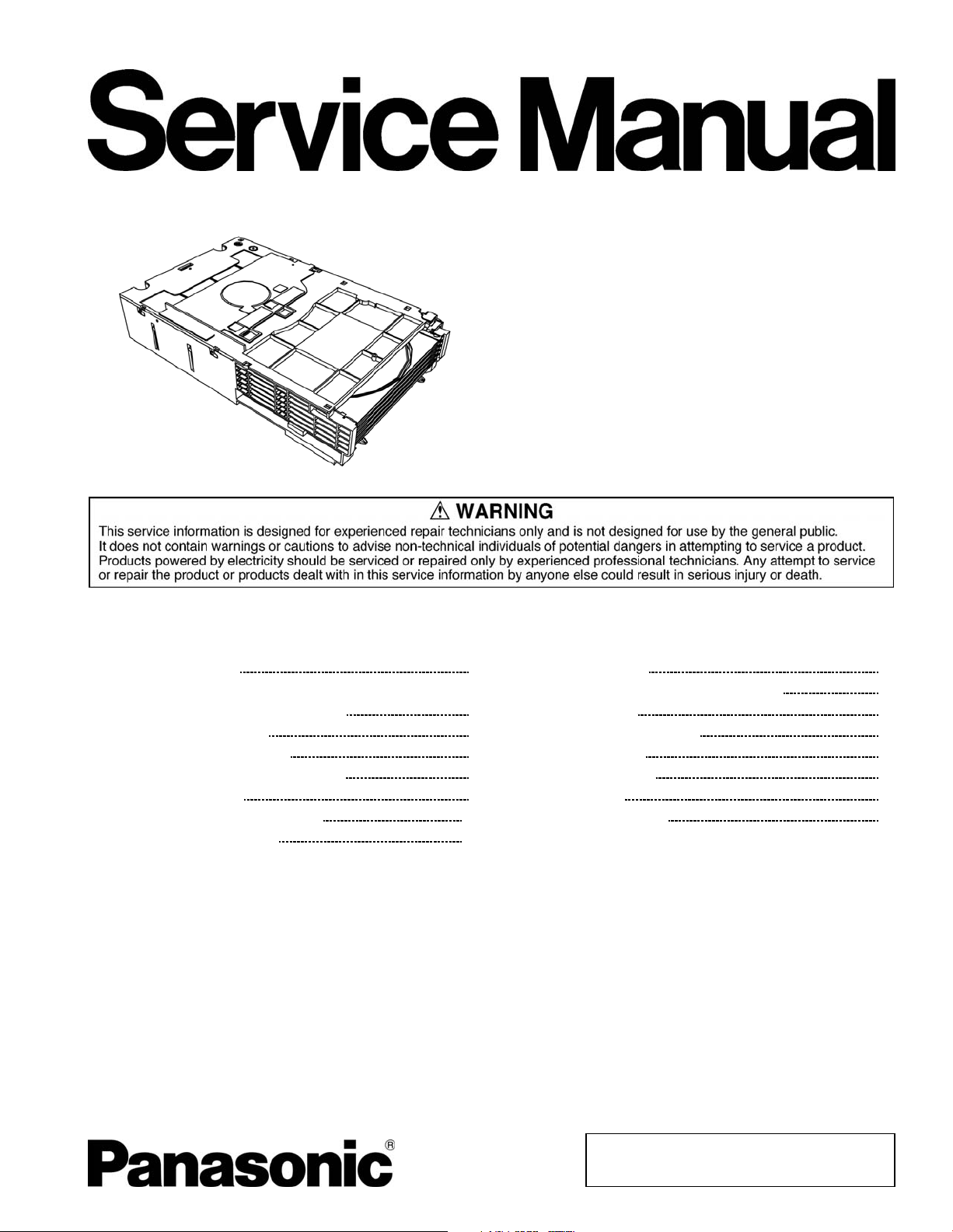
Mechanism Unit
CONTENTS
Page Page
1 Mechanism Overview 2
2 Prevention of Electrostatic Discharge (ESD) to
Electrostatically Sensitive (ES) Devices
3 Precaution of Laser Diode
4 About Lead Free Solder (PbF)
5 Handling Precautions for Traverse Unit
6 Mechanism Drive Unit
7 Mechanism Operations Description
8 CR14 Mechanism Reliability
9 Before Disassembly 16
10 Disassembling and Assembling Procedure
3
11 Disassembly Flow
12 Notes of Schematic Diagram
4
5
13 Schematic Diagram
6
14 Printed Circuit Board
15 Exploded Views
8
11
16 Replacement Parts List
12
24
61
63
64
65
67
69
© 2008 Matsushita Electric Industrial Co. Ltd.. All
rights reserved. Unauthorized copying and
distribution is a violation of law.
Page 2
CR14C
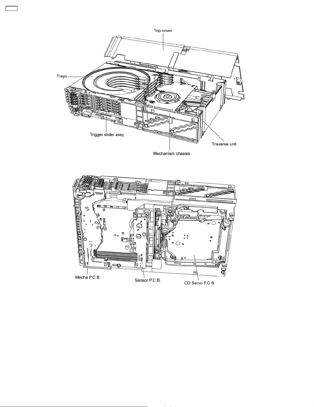
1 Mechanism Overview
2
Page 3

2 Prevention of Electrostatic Discharge (ESD) to
Electrostatically Sensitive (ES) Devices
Some semiconductor (solid state) devices can be damaged easily by static electricity. Such components commonly are called
Electrostatically Sensitive (ES) Devices. Examples of typical ES devices are integrated circuits and some field-effect transistors and
semiconductor "chip" components. The following techniques should be used to help reduce the incidence of component damage
caused by electrostatic discharge (ESD).
1. Immediately before handling any semiconductor component or semiconductor-equipped assembly, drain off any ESD on your
body by touching a known earth ground. Alternatively, obtain and wear a commercially available discharging ESD wrist strap,
which should be removed for potential shock reasons prior to applying power to the unit under test.
2. After removing an electrical assembly equipped with ES devices, place the assembly on a conductive surface such as
aluminum foil, to prevent electrostatic charge buildup or exposure of the assembly.
3. Use only a grounded-tip soldering iron to solder or unsolder ES devices.
4. Use only an anti-static solder removal device. Some solder removal devices not classified as "anti-static (ESD protected)" can
generate electrical charge sufficient to damage ES devices.
5. Do not use freon-propelled chemicals. These can generate electrical charges sufficient to damage ES devices.
6. Do not remove a replacement ES device from its protective package until immediately before you are ready to install it. (Most
replacement ES devices are packaged with leads electrically shorted together by conductive foam, aluminum foil or comparable
conductive material).
7. Immediately before removing the protective material from the leads of a replacement ES device, touch the protective material
to the chassis or circuit assembly into which the device will be installed.
Caution:
Be sure no power is applied to the chassis or circuit, and observe all other safety precautions.
8. Minimize bodily motions when handling unpackaged replacement ES devices. (Otherwise harmless motion such as the
brushing together of your clothes fabric or the lifting of your foot from a carpeted floor can generate static electricity (ESD)
sufficient to damage an ES device).
CR14C
3
Page 4
CR14C
3 Precaution of Laser Diode
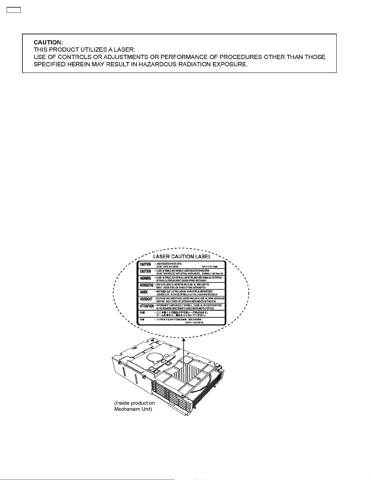
CAUTION :
This product utilizes a laser diode with the unit turned "on", invisible laser radiation is emitted from the pickup lens.
Wavelength: 655 nm (DVD)/785 nm (CD)
Maximum output radiation power from pickup: 100 µW/VDE
Laser radiation from the pickup unit is safety level, but be sure the followings:
1. Do not disassemble the pickup unit, since radiation from exposed laser diode is dangerous.
2. Do not adjust the variable resistor on the pickup unit. It was already adjusted.
3. Do not look at the focus lens using optical instruments.
4. Recommend not to look at pickup lens for a long time.
ACHTUNG :
Dieses Produkt enthält eine Laserdiode. Im eingeschalteten Zustand wird unsichtbare Laserstrahlung von der
Lasereinheitadgestrahit.
Wellenlänge: 655 nm (DVD)/785 nm (CD)
Maximale Strahlungsleistung der Lasereinhelt: 100 µW/VDE
Die strahlungan der Lasereinheit ist ungefährlich, wenn folgende Punkte beachtet werden:
1. Die Lasereinheit nicht zerlegen, da die Strahlung an der freigelegten Laserdiode gefährlich ist.
2. Den werksseitig justierten Einstellregler der Lasereinheit nicht verstellen.
3. Nicht mit optischen Instrumenten in die Fokussierlinse blicken.
4. Nicht über längere Zeit in die Fokussierlinse blicken.
4
Page 5

4 About Lead Free Solder (PbF)
4.1. Service caution based on legal restrictions
4.1.1. General description about Lead Free Solder (PbF)
The lead free solder has been used in the mounting process of all electrical components on the printed circuit boards used for this
equipment in considering the globally environmental conservation.
The normal solder is the alloy of tin (Sn) and lead (Pb). On the other hand, the lead free solder is the alloy mainly consists of tin
(Sn), silver (Ag) and Copper (Cu), and the melting point of the lead free solder is higher approx.30 degrees C (86°F) more than that
of the normal solder.
Definition of PCB Lead Free Solder being used
The letter of “PbF” is printed either foil side or components side on the PCB using the lead free solder.
(See right figure)
Service caution for repair work using Lead Free Solder (PbF)
• The lead free solder has to be used when repairing the equipment for which the lead free solder is used.
(Definition: The letter of “PbF” is printed on the PCB using the lead free solder.)
• To put lead free solder, it should be well molten and mixed with the original lead free solder.
• Remove the remaining lead free solder on the PCB cleanly for soldering of the new IC.
• Since the melting point of the lead free solder is higher than that of the normal lead solder, it takes the longer time to melt
the lead free solder.
• Use the soldering iron (more than 70W) equipped with the temperature control after setting the temperature at 350±30
degrees C (662±86°F).
Recommended Lead Free Solder (Service Parts Route.)
• The following 3 types of lead free solder are available through the service parts route.
RFKZ03D01K-----------(0.3mm 100g Reel)
RFKZ06D01K-----------(0.6mm 100g Reel)
RFKZ10D01K-----------(1.0mm 100g Reel)
CR14C
Note
* Ingredient: tin (Sn), 96.5%, silver (Ag) 3.0%, Copper (Cu) 0.5%, Cobalt (Co) / Germanium (Ge) 0.1 to 0.3%
5
Page 6
CR14C
5 Handling Precautions for Traverse Unit
The laser diode in the optical pickup unit may break down due to static electricity of clothes or human body. Specia l care must be
taken avoid caution to electrostatic breakdown when servicing and handling the laser diode in the traverse unit.
5.1. Cautions to Be Taken in Handling the Optical Pickup Unit
The laser diode in the optical pickup unit may be damaged due to electrostatic discharge generating from clothes or human body.
Special care must be taken avoid caution to electrostatic discharge damage when servicing the laser diode.
1. Do not give a considerable shock to the optical pickup unit as it has an extremely high-precise structure.
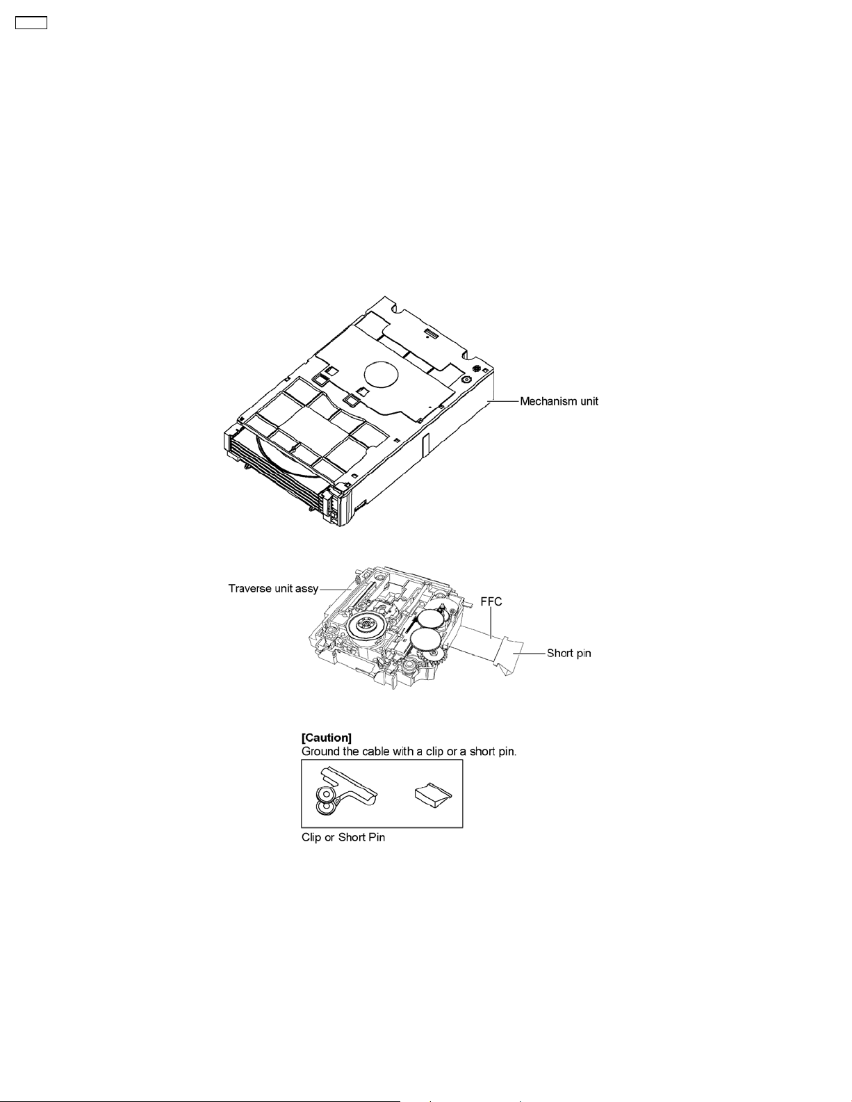
2. To prevent the laser diode from the electrostatic discharge damage, the flexible cable of the optical pickup unit removed should
be short-circuited with a short pin or a clip.
3. The flexible cable may be cut off if an excessive force is applied to it. Use caution when handling the flexible cable.
4. The antistatic FPC is connected to the new optical pickup unit. After replacing the optical pickup unit and connecting the flexible
cable, cut off the antistatic FPC.
5.2. Grounding for electrostatic breakdown prevention
Some devices such as the CD player use the optical pickup (laser diode) and the optical pickup will be damaged by static electricity
in the working environment. Proceed servicing works under the working environment where grounding works is completed.
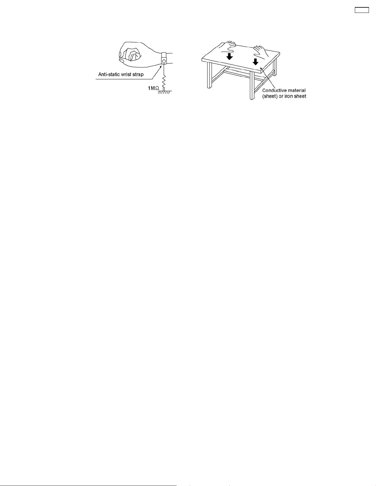
5.2.1. Worktable grounding
1. Put a conductive material (sheet) or iron sheet on the area where the optical pickup is placed, and ground the sheet.
5.2.2. Human body grounding
1. Use the anti-static wrist strap to discharge the static electricity form your body.
6
Page 7
CR14C
7
Page 8
CR14C
6 Mechanism Drive Unit
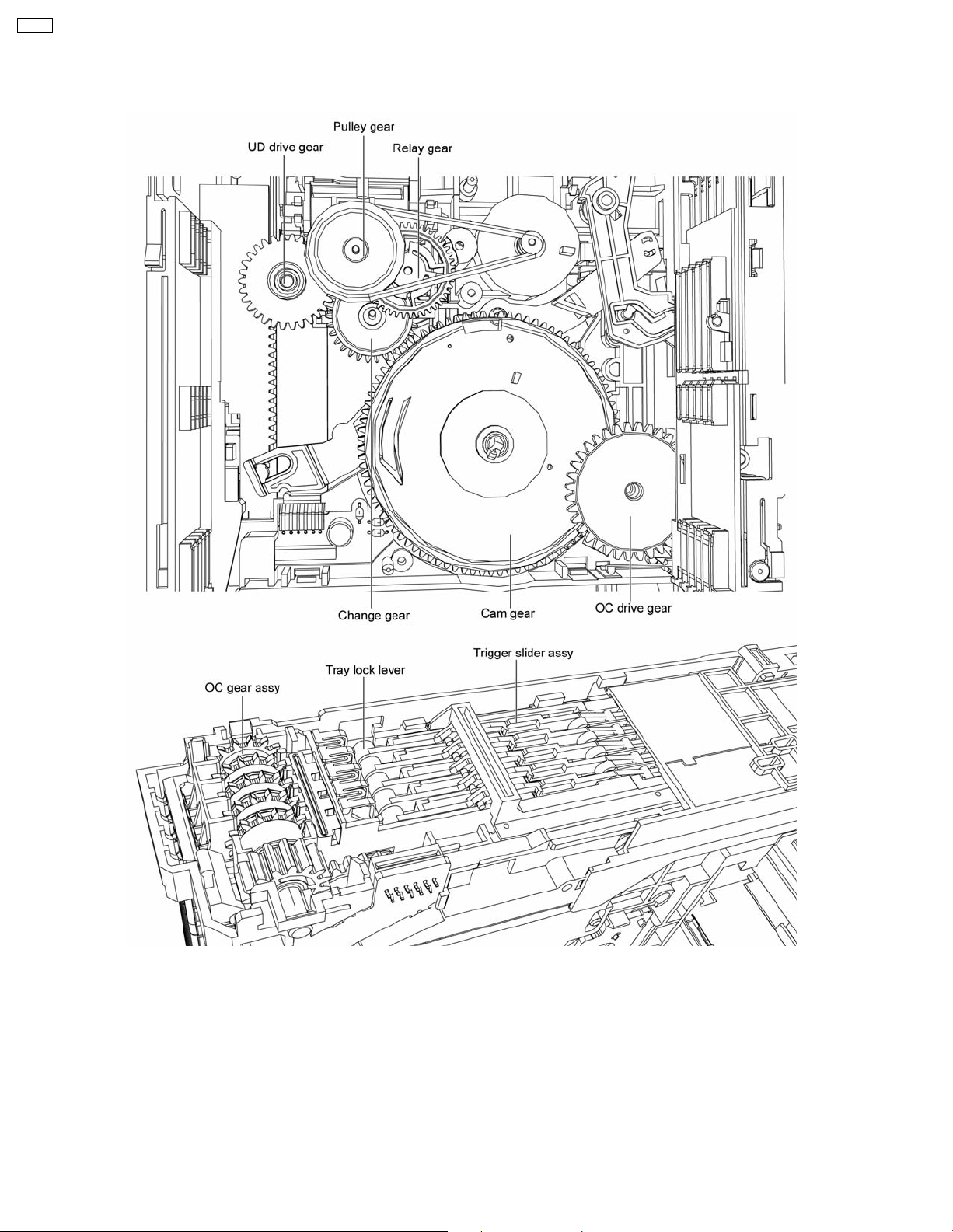
6.1. Description of trays open/close and discs exchange operations
1. The loading motor turns in the clockwise direction and the rotation is transmitted via the belt, the pulley gear also turns clockwise.
2. The relay gear turns counter clockwise.
3. The change gear turns clockwise.
4. The cam gear turns counter clockwise.
5. The OC drive gear turns clockwise driven OC gear assy.
6. Trigger slide assy releases tray lock lever.
7. Movement of OC gear assy releases all trays.
(The operation of trays closed is the opposi te of that for opening trays. Discs exchange is done during closing operation.)
8
Page 9
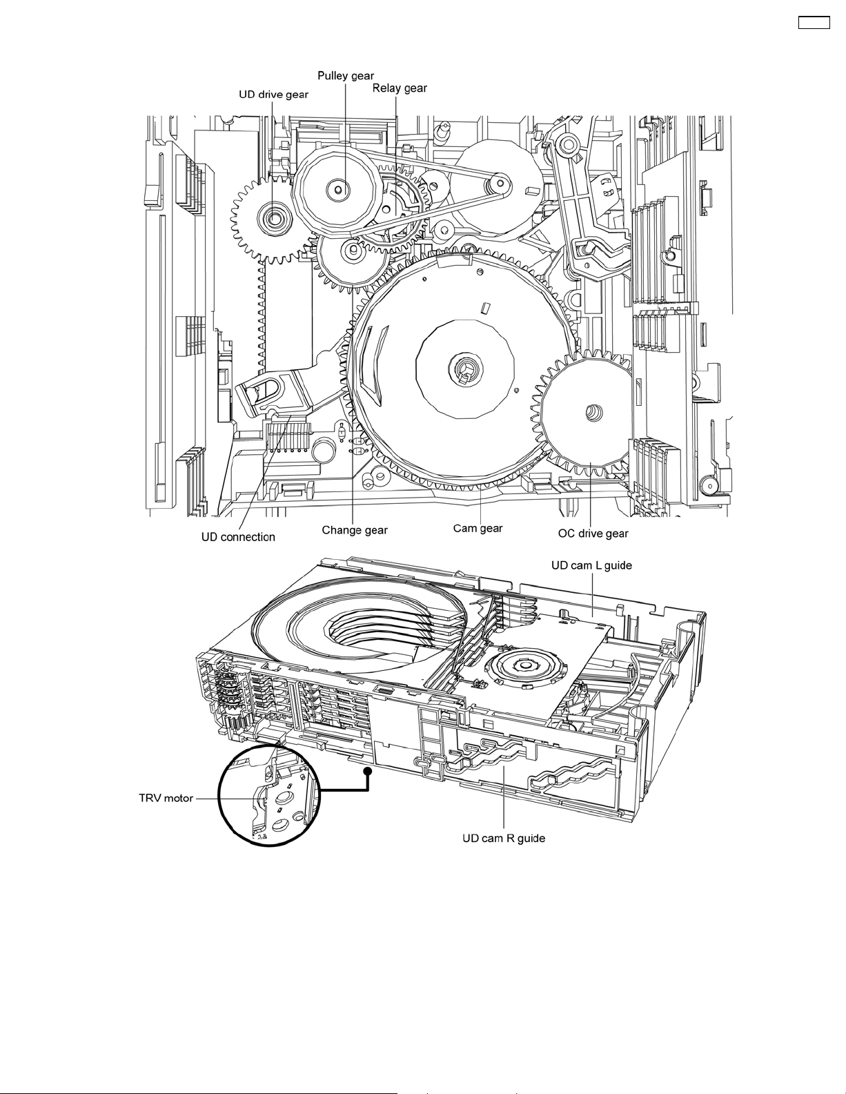
6.2. Description of tray selection operation
CR14C
1. The loading motor turns in the clockwise direction and the rotation is transmitted via the belt, the pulley gear also turns clockwise.
2. The relay gear turns counter clockwise.
3. The change gear turns clockwise.
4. The cam gear turns counter clockwise.
5. The UD drive gear turns counter clockwise engages UD cam L guide drives UD connection turns counter clockwise, UD cam R
guide is driven to move UD base unit down.
(The operation of the UD base unit up is the opposite of that for the UD base unit down.)
9
Page 10
CR14C
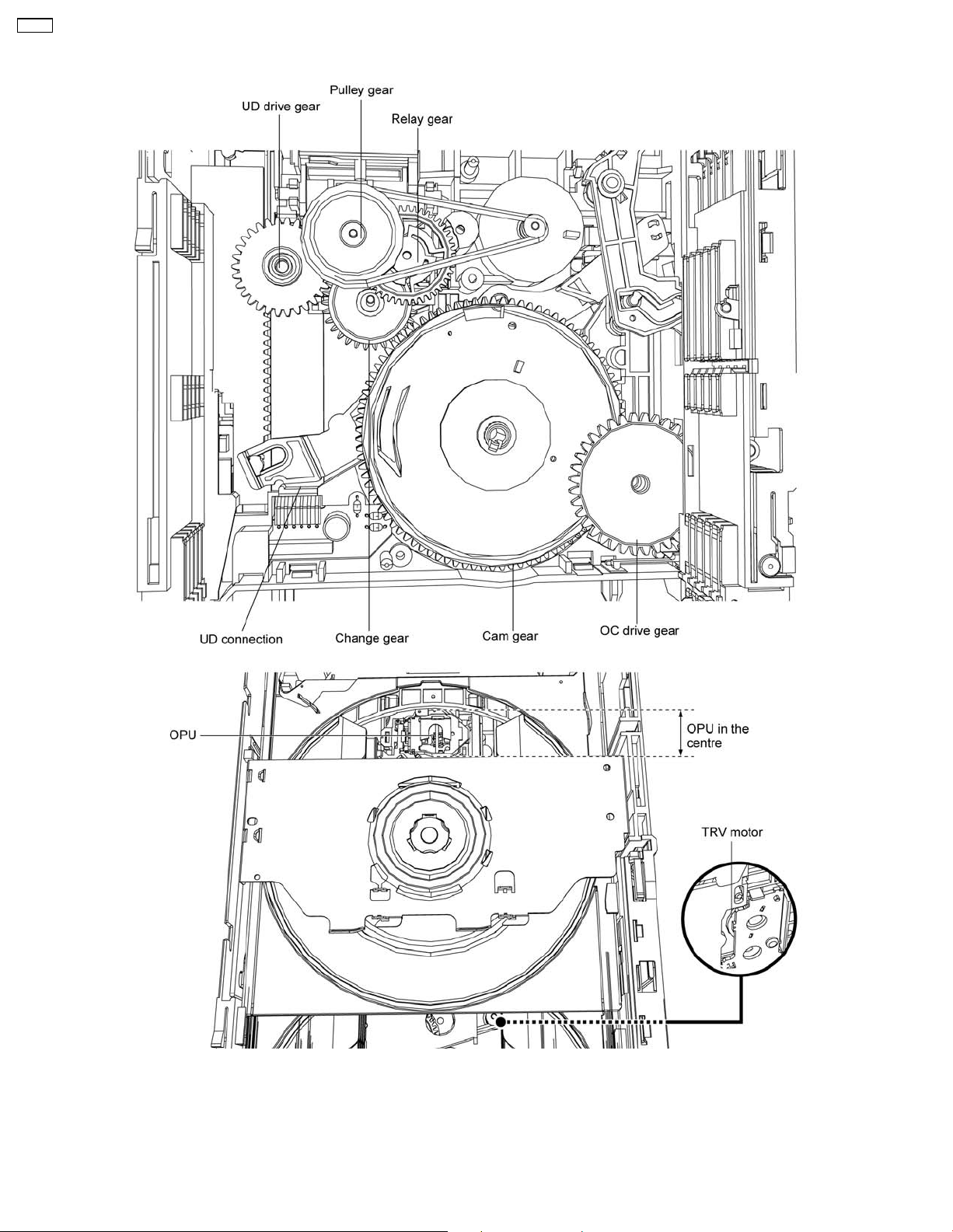
6.3. Description of play operation
1. The loading motor turns in the clockwise direction and the rotation is transmitted via the belt, the pulley gear also turns cloc
2. The relay gear turns counter clockwise.
3. The change gear turns clockwise.
4. The cam gear turns counter clockwise.
5. Turn the TRV motor clockwise, the tray will load into play position until OPU at the centre position.
10
Page 11

7 Mechanism Operations Description
This section is not available at the time of issue.
CR14C
11
Page 12
CR14C
8 CR14 Mechanism Reliability
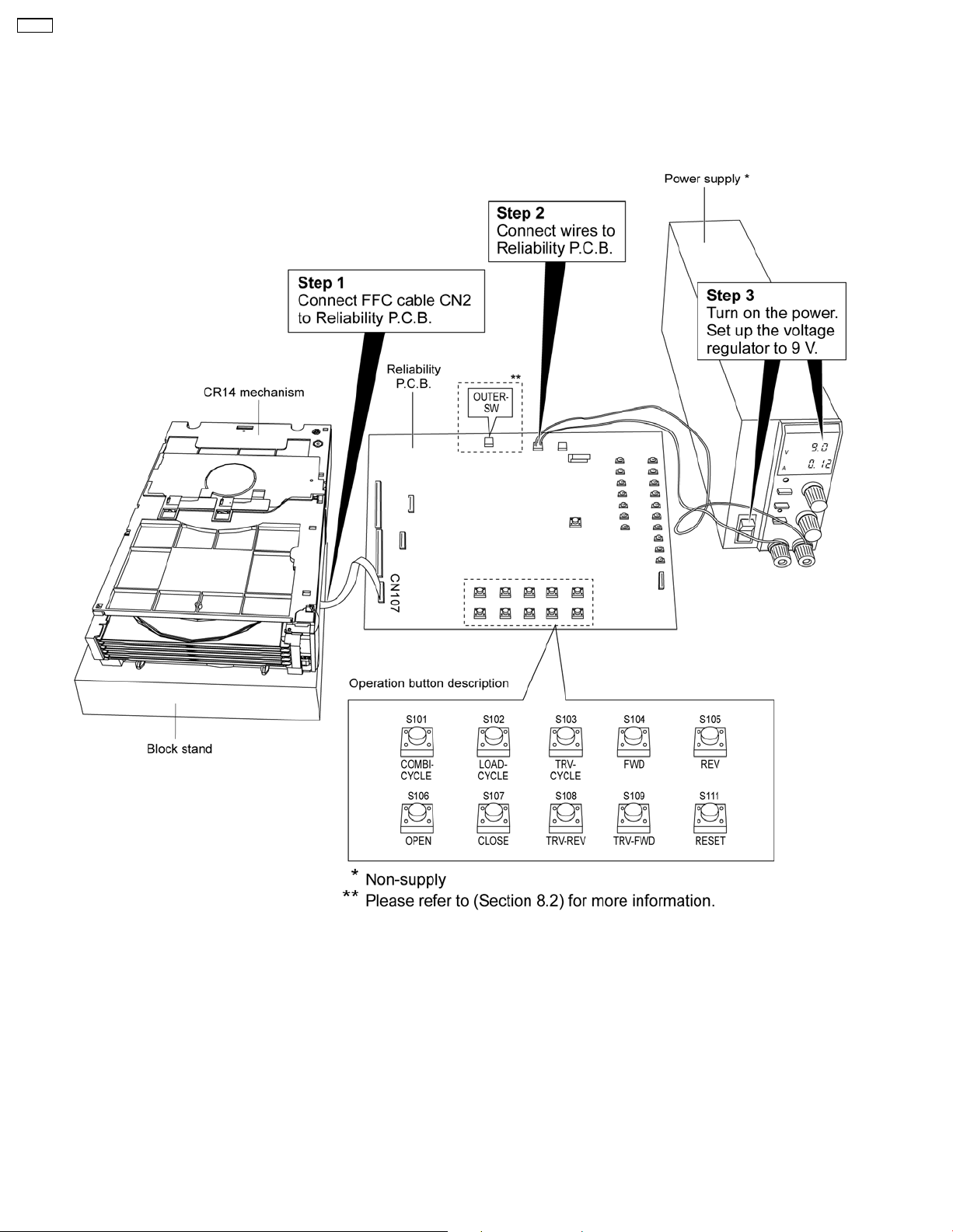
Purpose: To test the CR14C mechanism unit operation by using the Reliability P.C.B. before installation into the main unit.
8.1. Setup Connection
Below diagram shows the set-up necessary to carry out the reliability of mechanism.
Equipments required for the set up preparation:
- Power supply
- Reliability P.C.B. (RFKZCR14)
12
Page 13
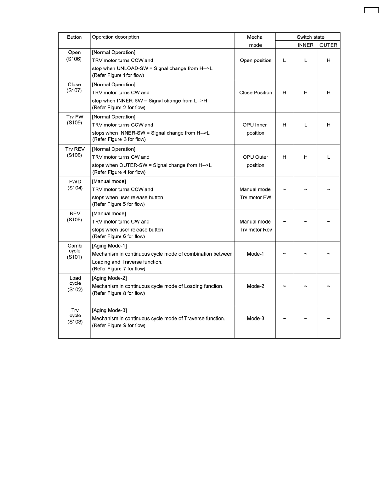
8.2. Jig’s Flow Diagram
CR14C
13
Page 14
CR14C
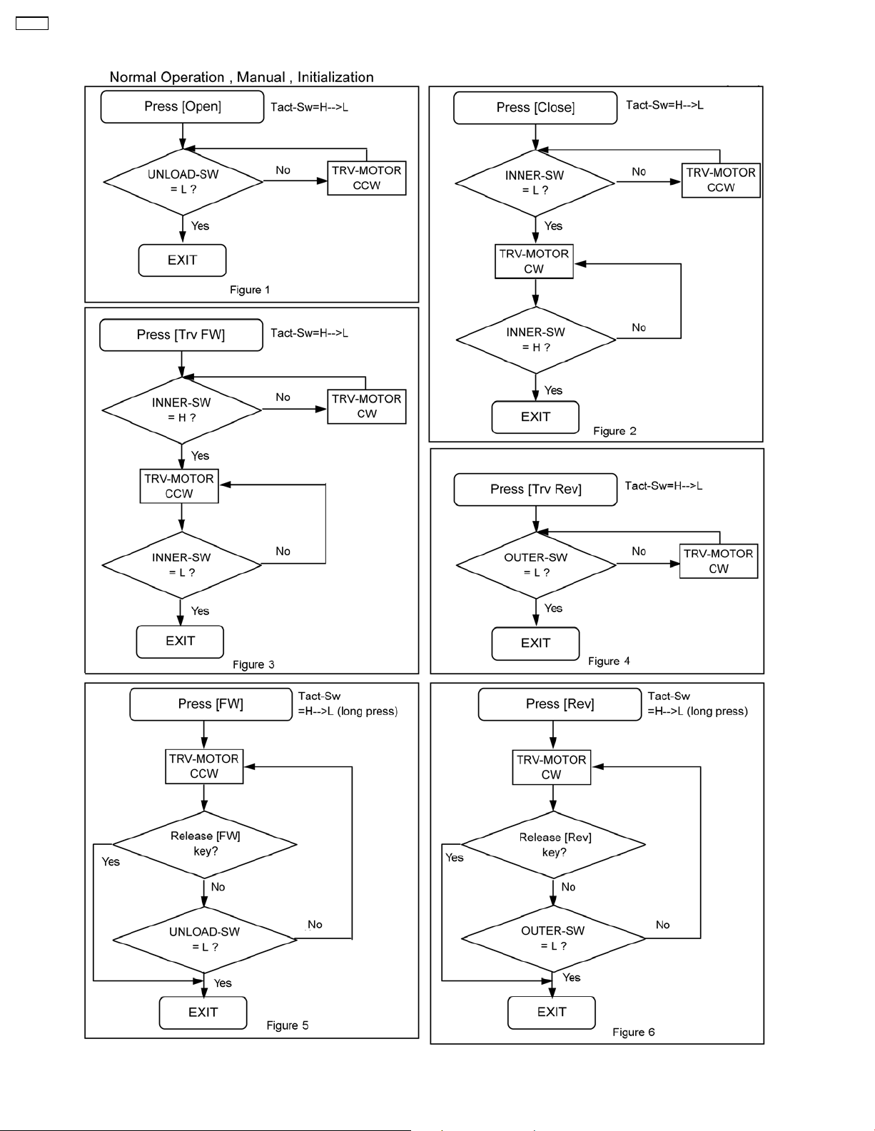
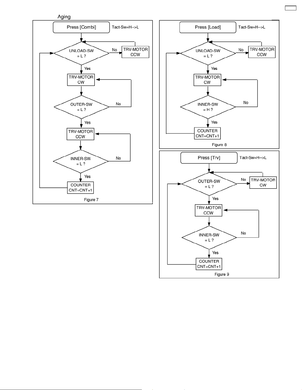
8.2.1. Flow operation
14
Page 15
CR14C
15
Page 16
CR14C
9 Before Disassembly
9.1. Using Service Modes (Main
Unit)
9.1.1. In Service Mode 1
Purpose:
All trays in “STOCK” position, UD base unit at tray 5
position.
Refer to Section 10.2 for disassembling of Mechanism
unit.
Procedures:
• Press and hold “STOP” button followed by “FORWARD”
button to enter TEST mode.
• Press [1] button on main unit to enter Service Mode 1.
9.1.2. In Service Mode 2
Purpose:
In “PLAY” position, OPU at the centre position (see section
6.3 for more information).
Refer to Section 10.1 for disassembling of Traverse unit
assy.
9.2. Using Manually
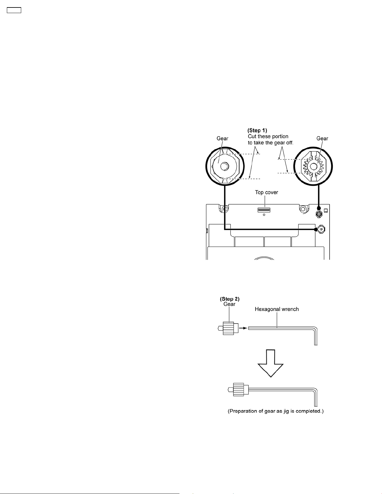
• Preparation of service jig
- This unit has two gears which are used for checking items
(open/close of tray, up/down operation of traverse unit by
manually) when servicing. (For gear information, that is
described on the items for disassembly procedures.)
- For preparation of gear (for servicing), perform the
procedures as follows.
- In case of re-servicing the same set, the “gear for
servicing” may be took off because it had been used. So,
the “gear for servicing” must be stored.
Procedures:
• Press and hold “STOP” button followed by “FORWARD”
button to enter TEST mode.
• Press [2] button on main unit to enter Service Mode 2.
Step 1: Cut the gear out from the top cover.
Note: The bigger gear is for loading hole and the smaller gear
is for traverse hole.
Step 2: Insert the gear into the hexago nal wrench.
16
Page 17
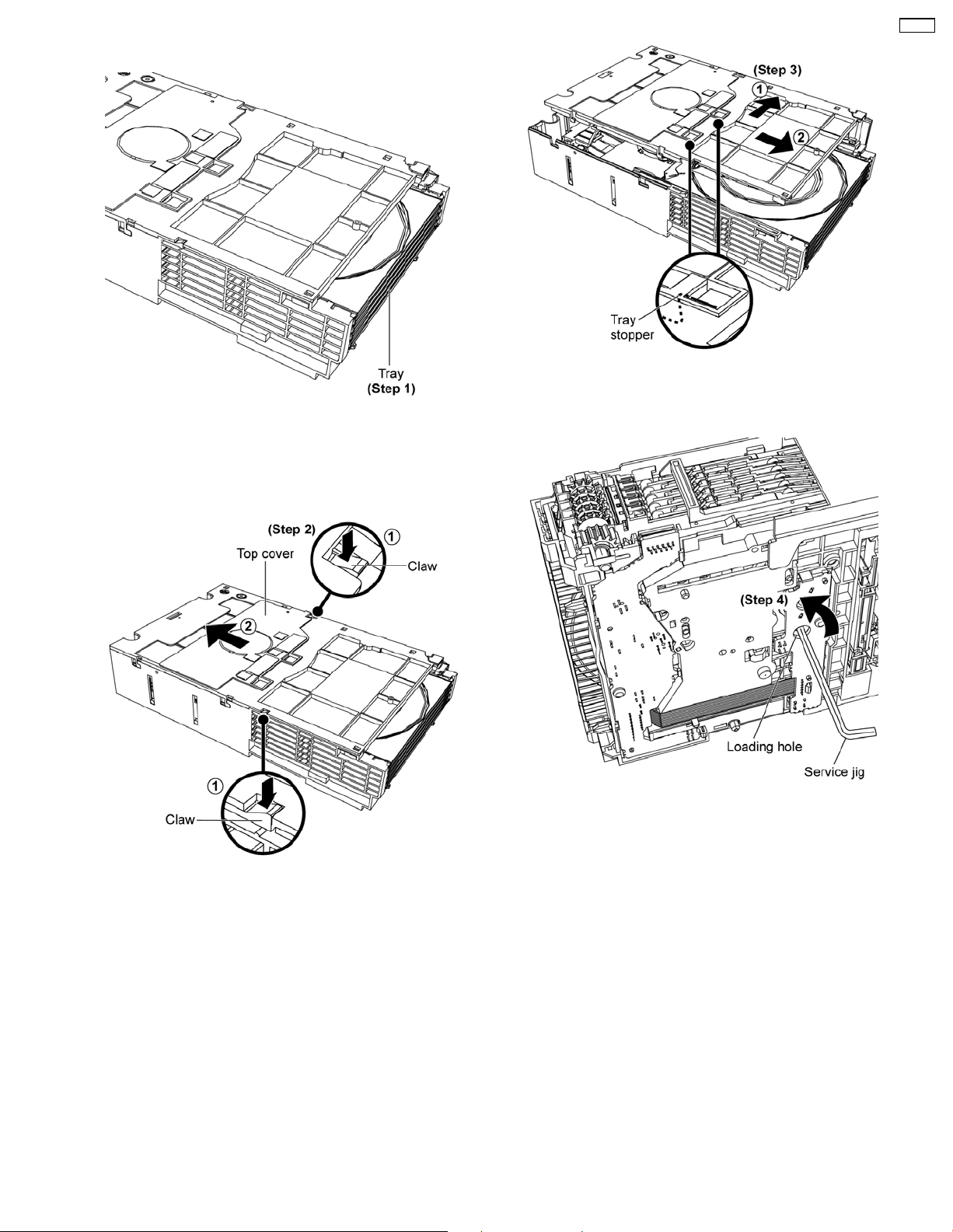
9.2.1. Manually set to “UD” position
Step 1: Check any missing tray at the mechanism front.
Caution:
The missing tray is engaged in the play position.
CR14C
Step 3: Remove the top cover as arrows shown to release the
tray stoppers.
Step 2: Press both claws at the sides as arrows shown and
push the top cover backwards.
Step 4: Insert service jig into the loading hole, rotate the gear
counter clockwise.
17
Page 18
CR14C
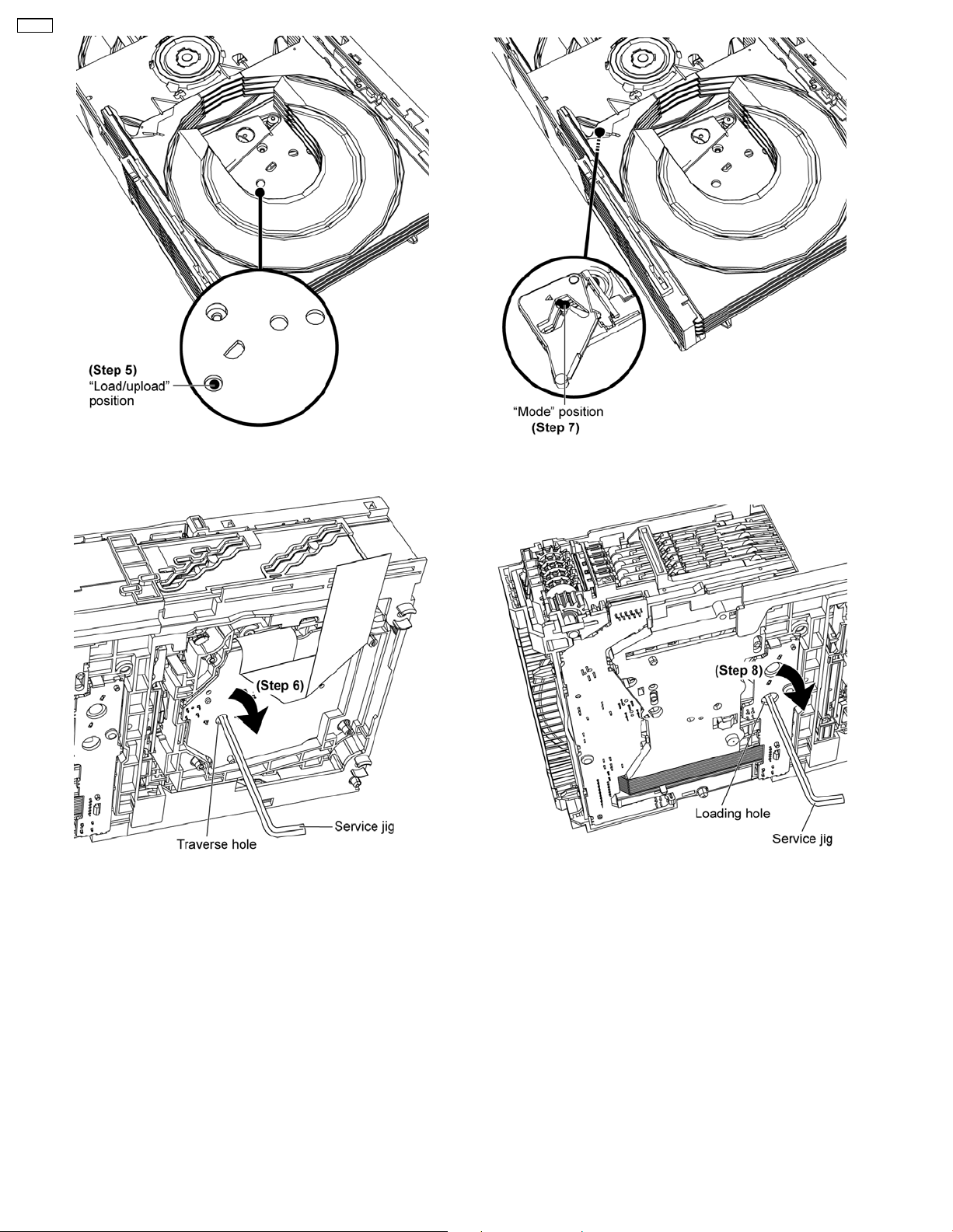
Step 5: Rotate the gear to “Load/upload” position.
Step 6: Insert service jig into the traverse hole, rotate the gear
clockwise.
Step 7: Rotate the gear to “Mode” position.
Step 8: Insert service jig into the loading hole, rotate the gear
clockwise.
18
Page 19
CR14C
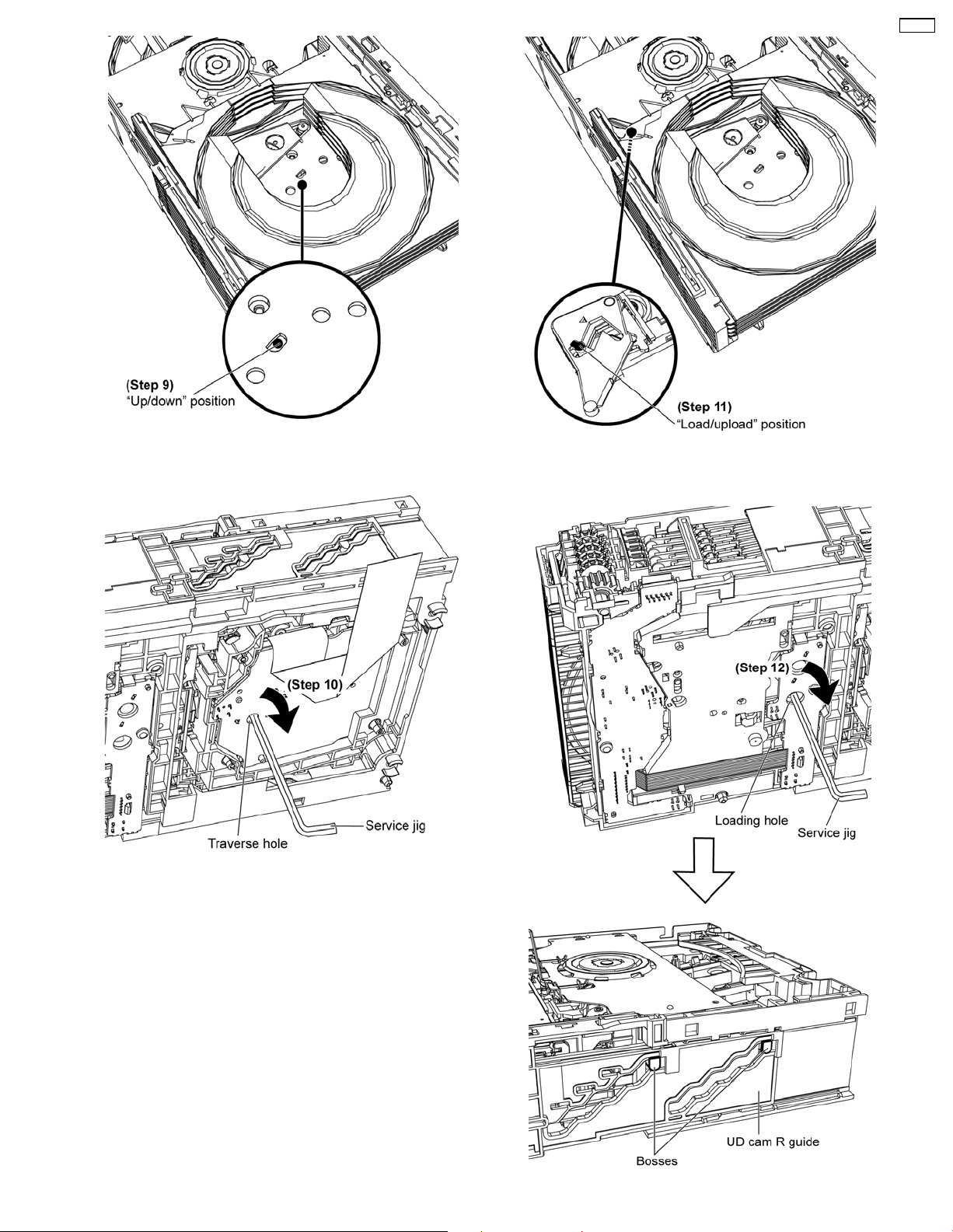
Step 9: Rotate the gear to “Up/down” position.
Step 10: Insert service jig into the traverse hole, rotate the gear
clockwise.
Step 11: Rotate the gear to “Load/upload” position.
19
Page 20
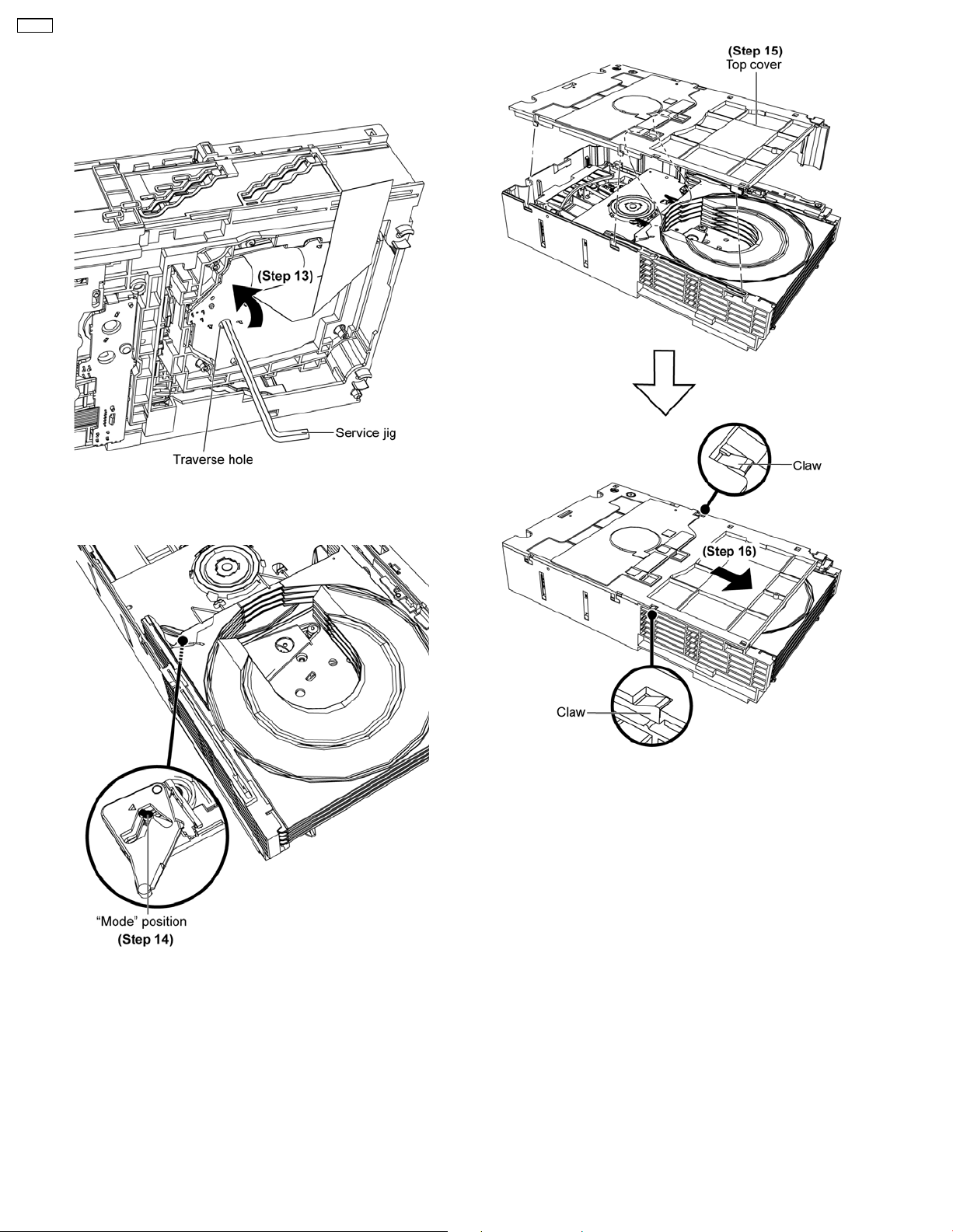
CR14C
Step 12: Insert service jig into the loading hole, rotate the gear
clockwise until both bosses positioned at the top of the UD cam
R guide.
Step 13: Insert service jig into the traverse hole, rotate the gear
counter clockwise.
Step 15: Attach the top cover to the tray stoppers.
Step 16: Slide the top cover as arrow shown.
Note: Ensure both claws are catched.
(Refer to Section 10.2 for disassembling of Mechanism
unit.)
Step 14: Rotate the gear to “Mode” position.
20
Page 21
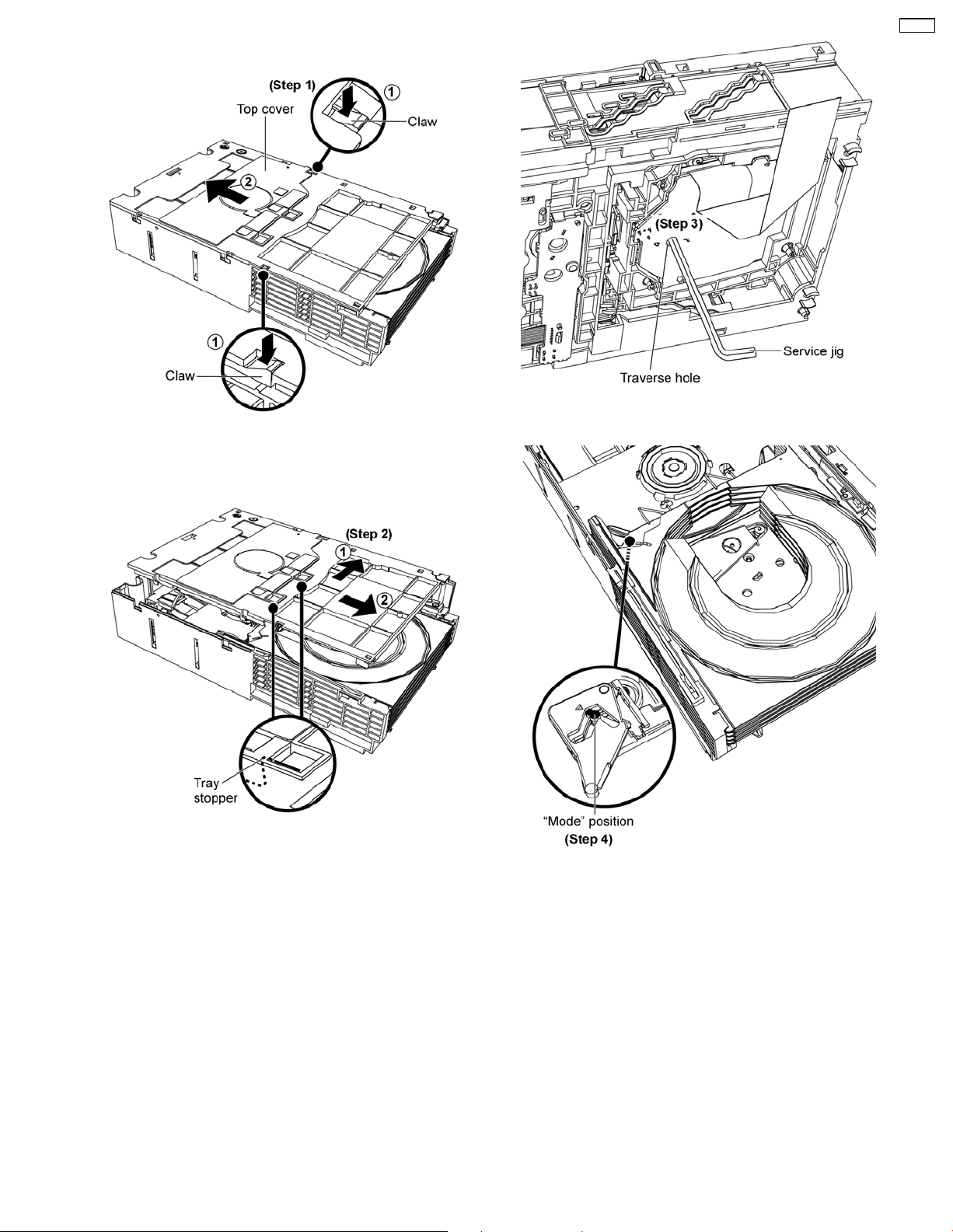
9.2.2. Manually set to “PLAY” position
Step 1: Press both claws at the sides as arrows shown and
push the top cover backwards.
CR14C
Step 3: Insert service jig into the traverse hole.
Step 2: Remove the top cover as arrows shown to release the
tray stoppers.
Step 4: Rotate the gear to “Mode” position.
21
Page 22
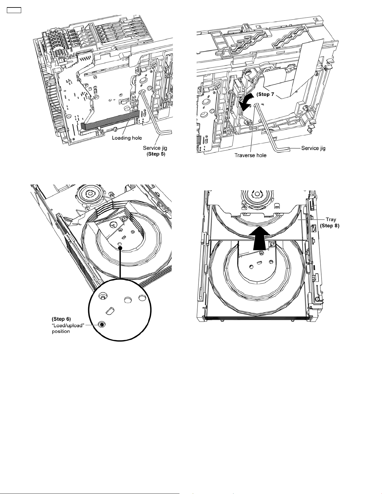
CR14C
Step 5: Insert service jig into the loading hole.
Step 7: Insert service jig into the traverse hole, rotate the gear
counter clockwise.
Step 8: The tray gradually move to the play position.
Step 6: Rotate the gear to “Load/Upload” position.
22
Page 23
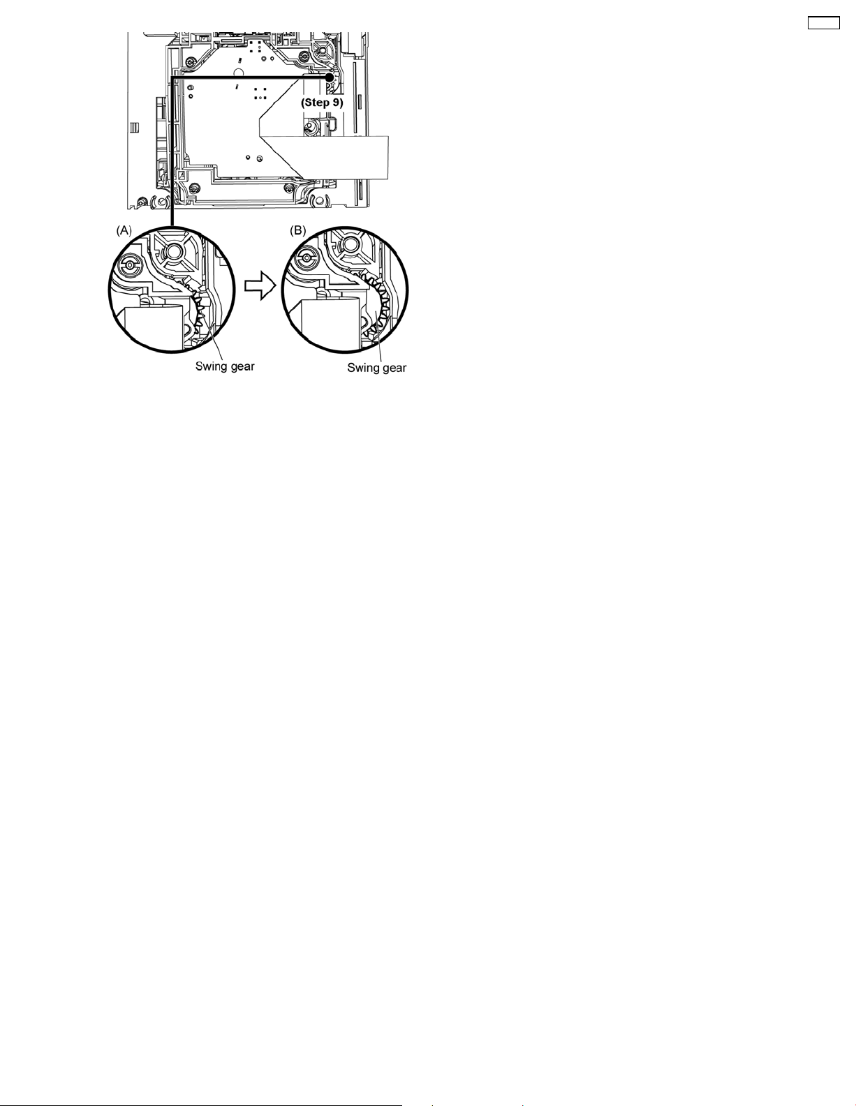
Step 9: Rotate the traverse hole continuously, until the swing
gear from position (A) to (B).
CR14C
(Refer to Section 10.1 for disassembling of Traverse unit
assy.)
23
Page 24
CR14C
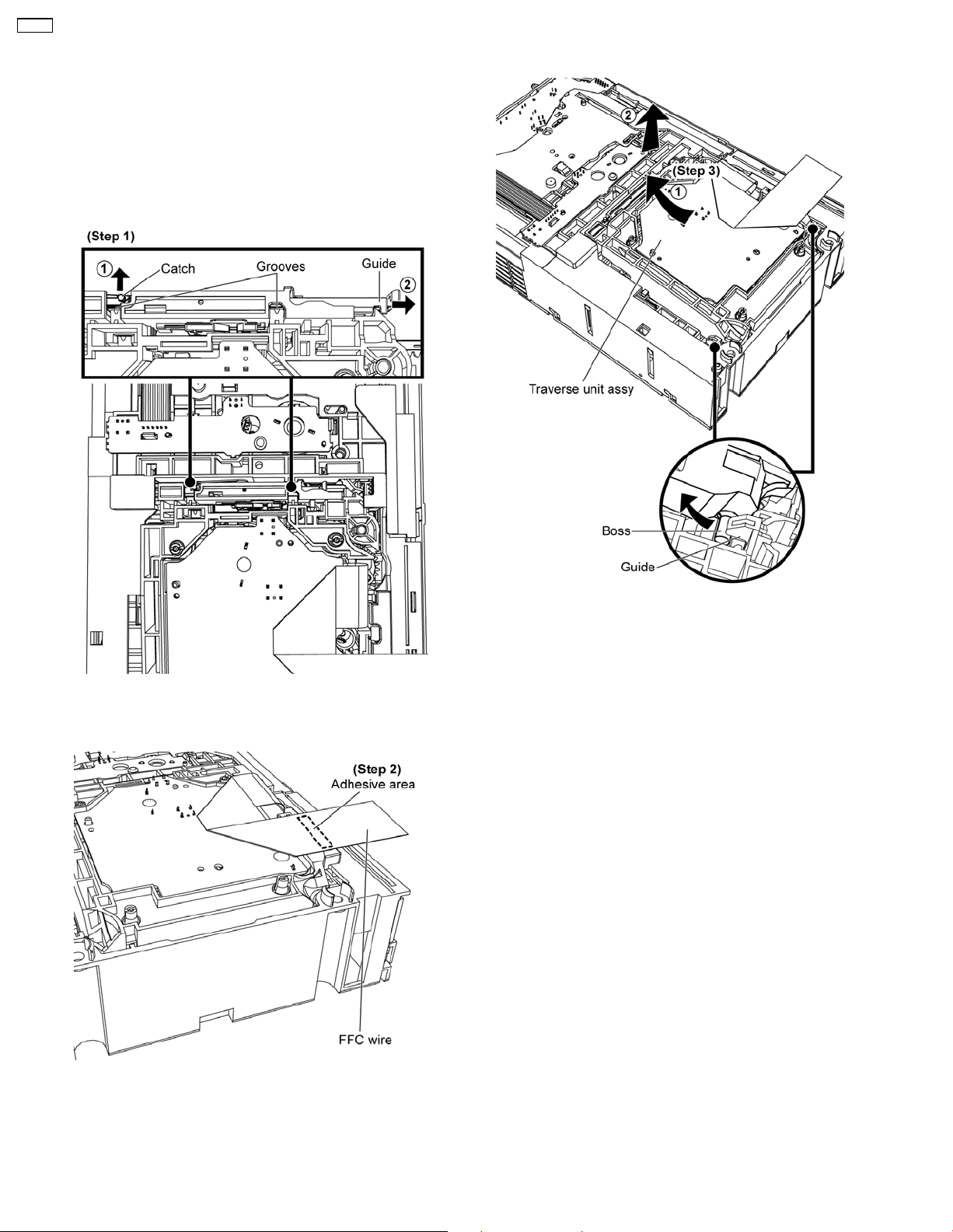
10 Disassembling and Assembling Procedure
10.1. Disassembling and
assembling Traverse Unit
Assy in play position
10.1.1. Disassembly of Traverse Unit Assy
Step 1: Release the catch and push the guide as arrows shown
to open both grooves.
Step 3: Remove the traverse unit assy as arrows shown.
Step 2: Detach the FFC wire from the adhesive area.
24
Page 25
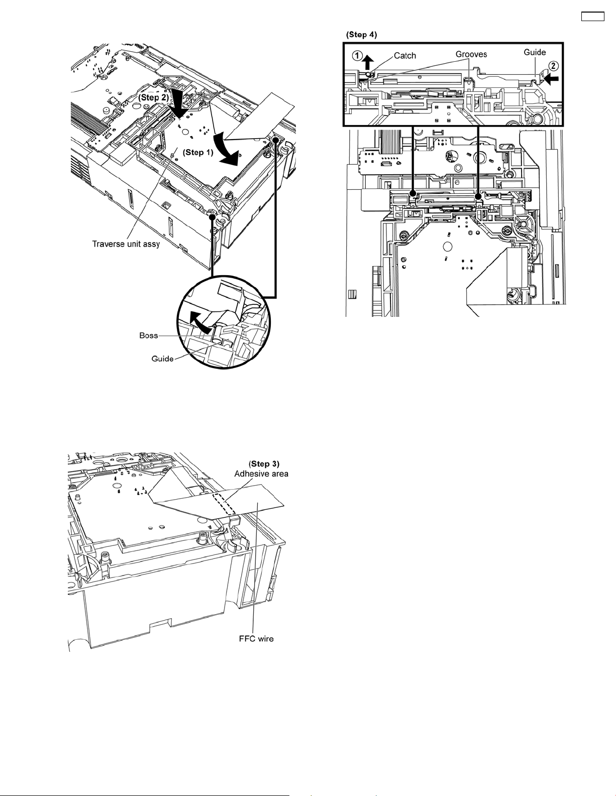
10.1.2. Assembly of Traverse Unit Assy
CR14C
Step 1: Slot the traverse unit assy into the guides as arrow
shown.
Note: Ensure the bosses fix exactly onto the guides.
Step 2: Place down the traverse unit assy.
Step 4: Release the catch and push the guide as arrows shown
to close both grooves.
Step 3: Fix the FFC wire by using the adhesive tape.
25
Page 26
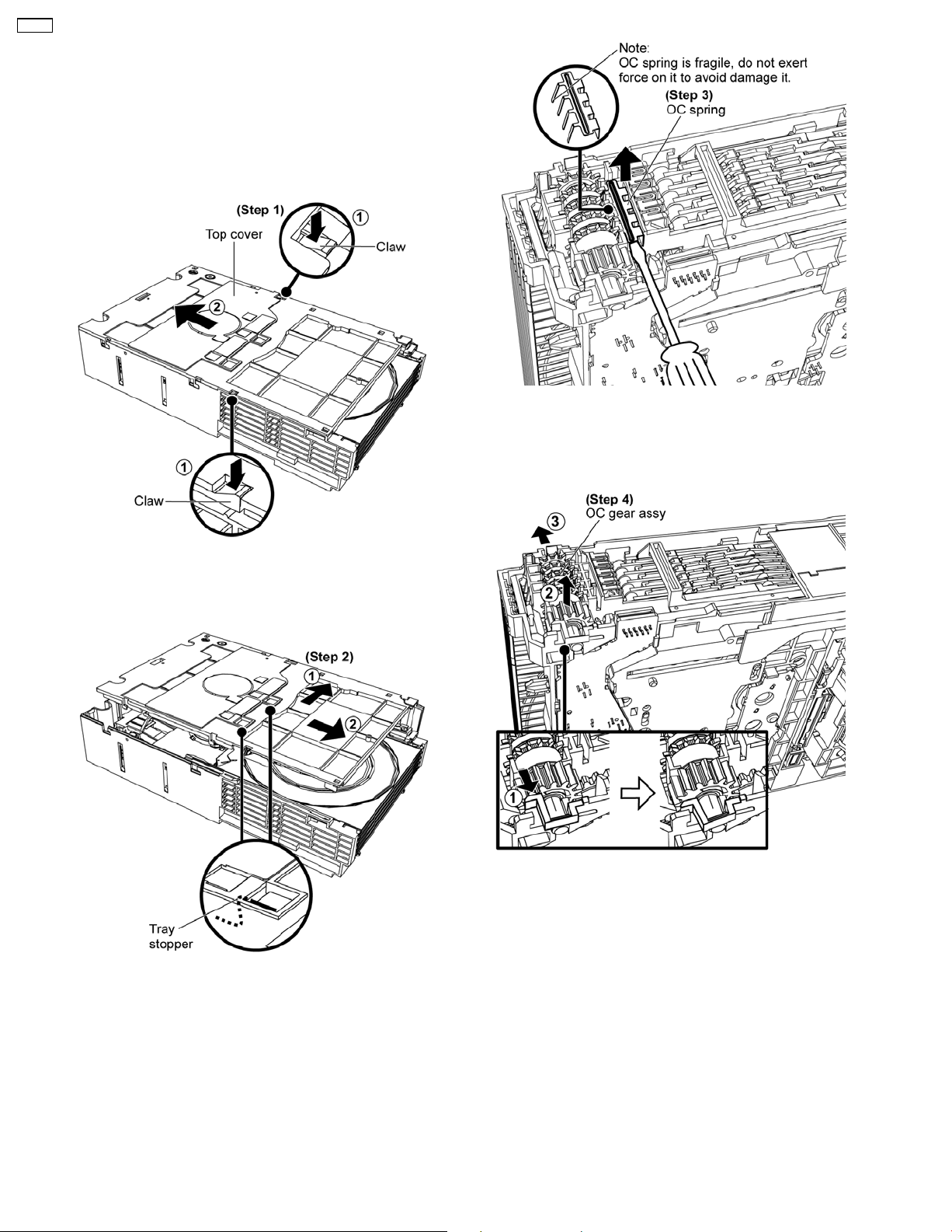
CR14C
10.2. Disassembling of Mechanism
Unit in “UD” Position
Note: Mechanism unit (CR14C) reliability test can be carried
out in complete unit or using the Reliability P.C.B (Refer to
section 8).
10.2.1. Disassembly of UD Base Unit
Step 3: Use a flathead screwdriver to remove OC spring.
Note: Ensure the OC spring is handle properly and keep it in a
safe place.
Step 1: Press both claws at the sides as arrows shown and
push the top cover backwards.
Step 2: Remove the top cover as arrows shown to release the
tray stoppers.
Step 4: Remove OC gear assy as arrows shown.
Note: Ensure the OC gear assy is handle properly and keep it
in a safe place.
26
Page 27
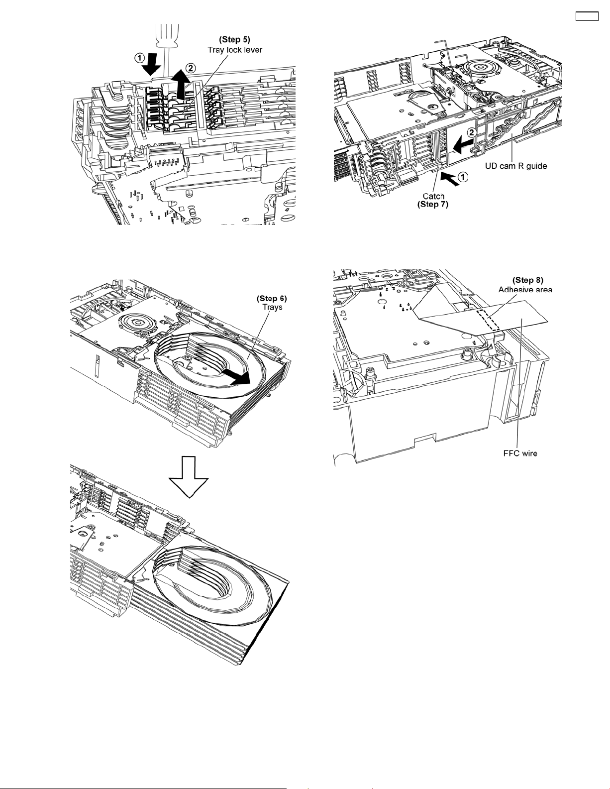
CR14C
Step 5: Use a flathead screwdriver slot into the gap and push
out the tray lock lever as arrows shown.
Step 7: Push the catch and slide the UD cam R guide as arrows
shown.
Step 8: Turn over the unit and detach the FFC wire from the
adhesive area.
Step 6: Push the trays towards the front as arrow shown.
27
Page 28
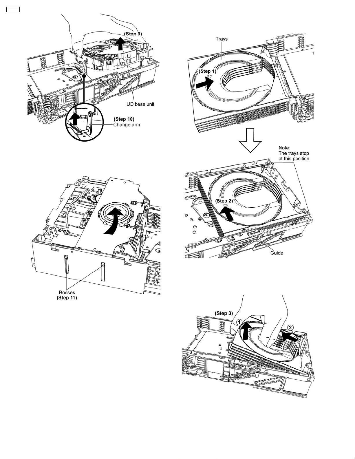
CR14C
Step 9: Lift up the UD base unit.
Step 10: Release the change arm.
10.2.2. Disassembly of Trays
• Follow (Step 1) to (Step 11) in item 10.2.1.
Step 11: Remove the UD base unit as arrow shown.
Step 1: Push the trays as arrow shown until they stop (bottom
picture).
Step 2: Tilt the trays towards one side as arrow shown.
Step 3: Lift and remove the trays as arrows shown.
28
Page 29
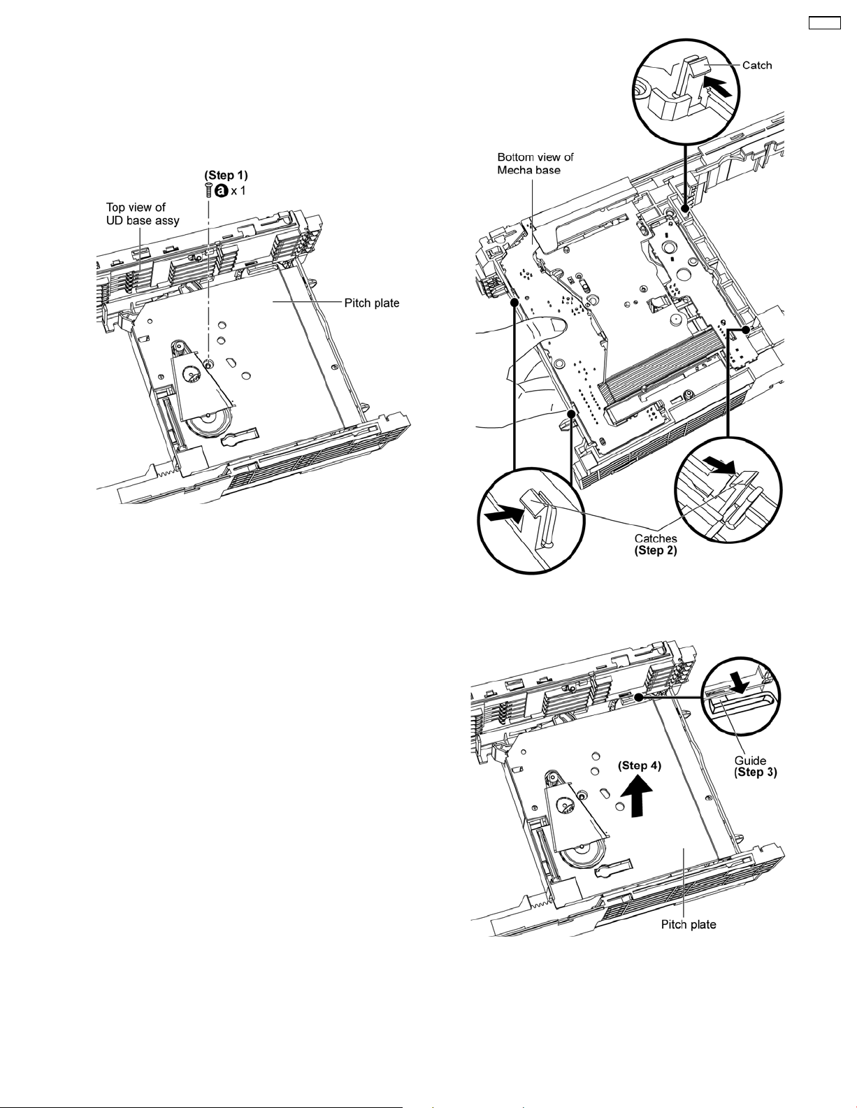
10.2.3. Disassembly of Mecha Base Unit
Parts
• Follow (Step 1) to (Step 11) in item 10.2.1.
• Follow (Step 1) to (Step 3) in item 10.2.2.
• Disassembly of Pitch Plate
CR14C
Step 1: Remove 1 screw.
Step 2: Release the catches.
Step 3: Release guide.
Step 4: Remove the pitch plate as arrow shown.
• Disassembly of OC Drive Gear
29
Page 30
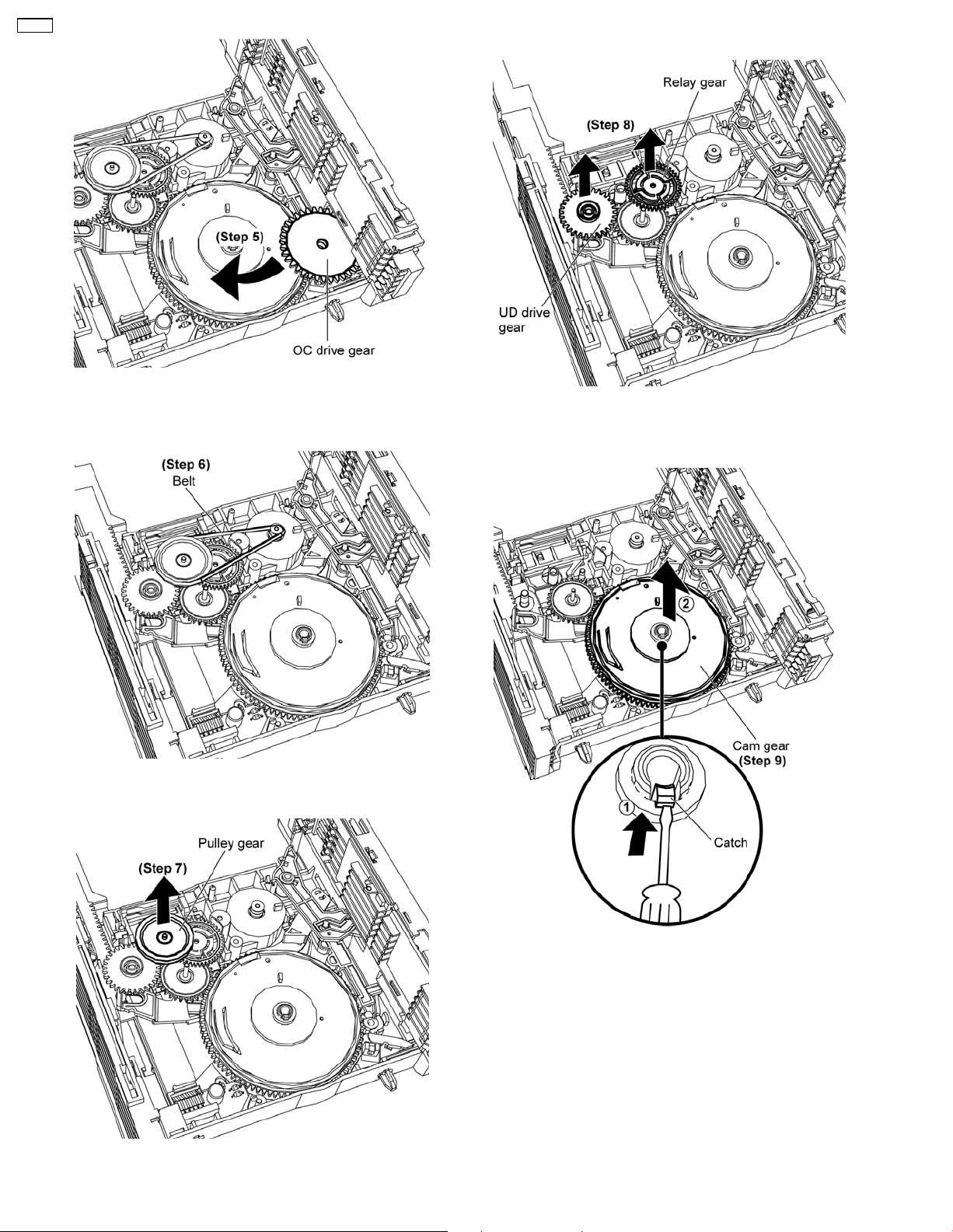
CR14C
Step 5: Remove OC drive gear as arrow shown.
• Disassembly of Belt and Pulley Gear
• Disassembly of Relay Gear and UD Drive Gear
Step 8: Remove relay gear and UD drive gear.
• Disassembly of Cam Gear
Step 6: Remove belt.
Step 7: Remove pulley gear.
Step 9: Use a flathead screwdriver to push the catch inwards
and remove cam gear as arrows shown.
30
Page 31
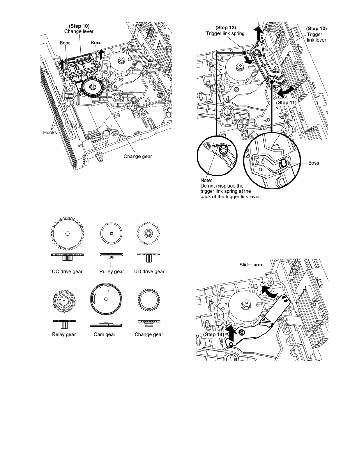
• Disassembly of Change Lever and Change Gear
CR14C
• Disassembly of Trigger Link Lever
Step 10: Release change lever’s bosses from the hooks and
remove both change lever and change gear together.
• Illustration of the gears
Step 11: Slide and hold the trigger link lever to the position as
picture shown.
Step 12: Release the trigger link spring.
Step 13: Remove the trigger link lever.
• Disassembly of Slider Arm
Step 14: Remove slider arm as arrows shown.
31
Page 32
CR14C
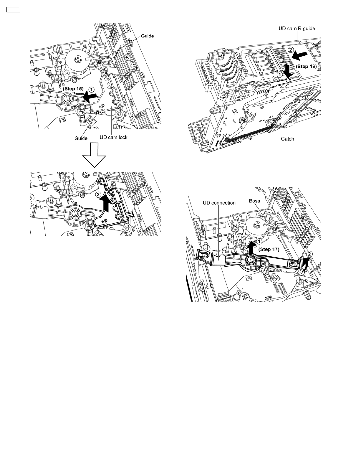
• Disassembly of UD Cam Lock
• Disassembly of UD Connection
Step 16: Push the catch and slide the UD cam R guide as
arrows shown.
Step 15: Release from the guides of the mecha base assy and
remove UD cam lock as arrows shown.
Step 17: Push up the UD connection from the centre and
detach it from the boss as arrows shown.
32
Page 33
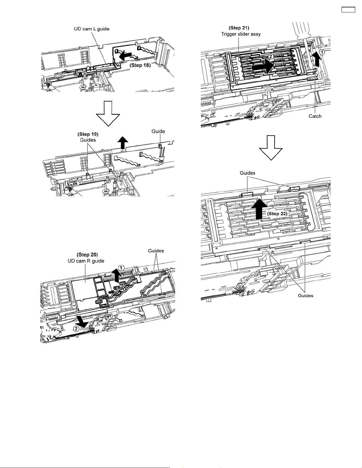
• Disassembly of UD Cam L Guide
CR14C
• Disassembly of Trigger Slider Assy
Step 18: Slide UD cam L guide as arrows shown.
Step 19: Ensure all guides align with the UD cam L guide’s
grooves and remove it as arrow shown.
• Disassembly of UD Cam R Guide
Step 20: Ensure both guides align with the UD cam R guide’s
grooves and remove it as arrows shown.
Step 21: Use a flathead screwdriver to release catch and slide
trigger slider assy to the end.
Step 22: Ensure all guides align with the trigger slider assy’s
grooves and remove it.
33
Page 34
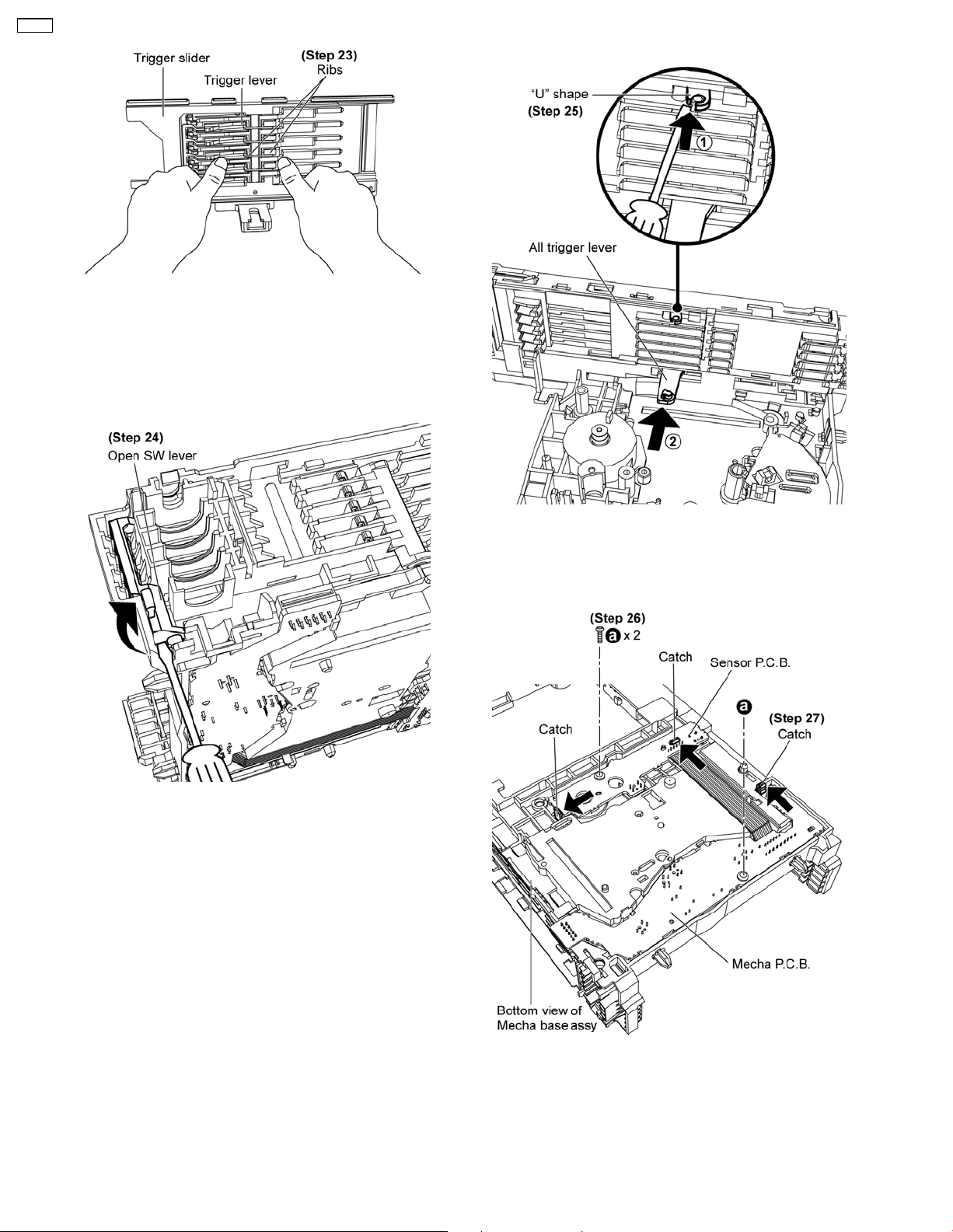
CR14C
Step 23: Press down individual ribs to detach trigger lever.
Caution:
Do not exert force as it may cause damage to the trigger
lever.
• Disassembly of Open Switch Lever
• Disassembly of All Trigger Lever
Step 24: Use a flathead screwdriver to push up the open switch
lever and remove it.
Step 25: Use a flathead screwdriver push the “U” shape and
push out the all trigger lever from the bottom.
• Disassembly of Mecha P.C.B. and Sensor P.C.B.
Step 26: Remove 2 screws.
Step 27: Release all catches to remove Mecha P.C.B. and
Sensor P.C.B.
34
Page 35
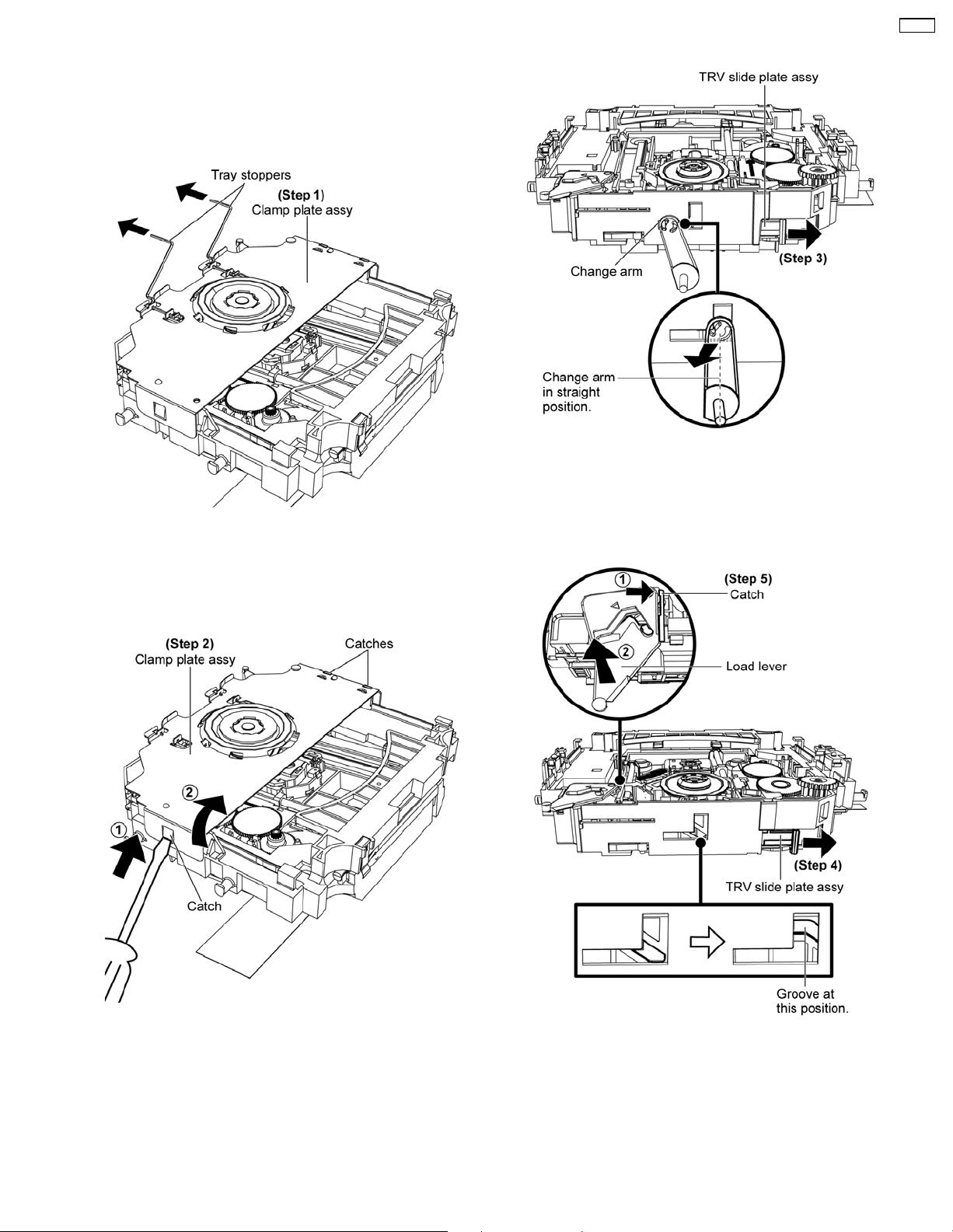
10.2.4. Disassembly of UD Base Unit
Parts
• Follow (Step 1) to (Step 11) in item 10.2.1.
• Disassembly of Tray Stoppers
CR14C
• Disassembly of Change Arm
Step 3: Slide the TRV slide plate assy until the change arm at
the position shown and remove the change arm as arrow
shown.
Step 1: Remove tray stoppers.
Note: Ensure the tray stoppers are handle properly and keep
them in a safe place.
• Disassembly of Clamp Plate Assy
• Disassembly of Load Lever
Step 2: Use a flathead screwdriver push the catch and
remove clamp plate assy as arrows shown.
Note: Be careful of the other side catches when removing
the clamp plate assy.
Step 4: Continue slide the TRV slide plate assy until the groove
at the position shown.
Step 5: Release catch and remove load lever as arrows shown.
35
Page 36
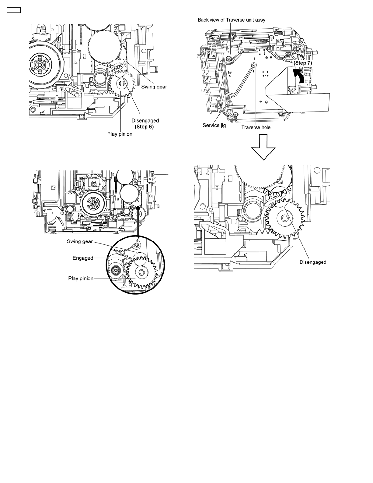
CR14C
• Disassembly of Traverse Unit Assy
Step 6: Check if the swing gear is disengaged from the play
pinion before disassembly.
Caution:
If it is engaged, the following steps are necessary.
Step 7: Insert service jig into the traverse hole, rotate the gear
counter clockwise, ensure the swing gear is disengaged.
36
Page 37
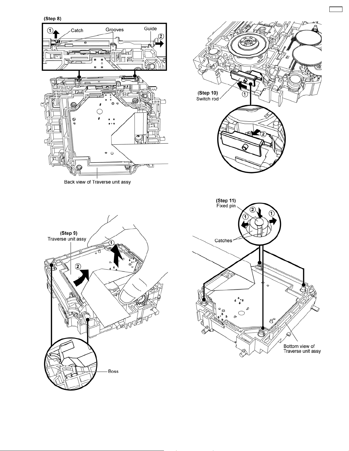
• Disassembly of Traverse Unit
CR14C
Step 8: Releas e catch and push the guide as arrows shown to
open the grooves.
Step 10: Slide the switch rod and remove it as arrows shown.
Step 9: Remove traverse unit assy as arrows shown.
Step 11: Release both catches and push down the fixed pin as
arrows shown.
37
Page 38
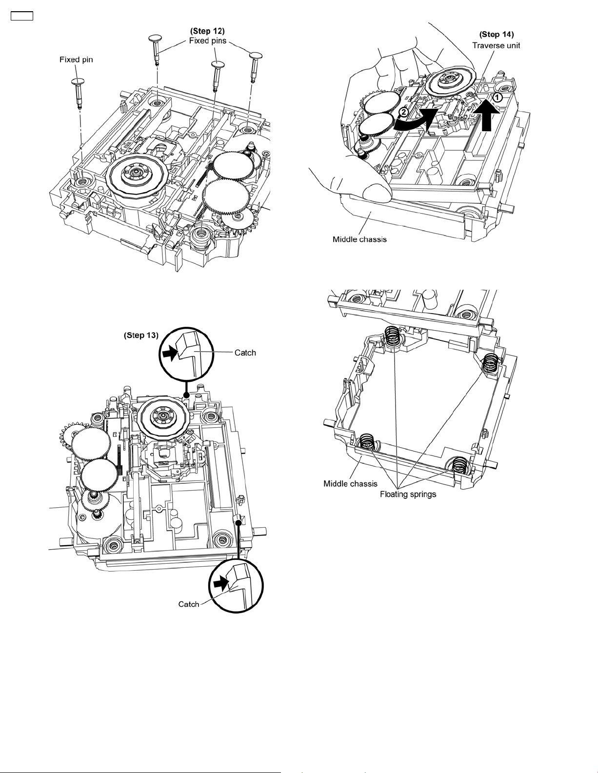
CR14C
Step 12: Remove 2 fixed pins from the top of the traverse unit
assy.
Step 14: Remove the traverse unit.
Step 13: Release the catches.
Note: Do not misplace 4 springs.
38
Page 39
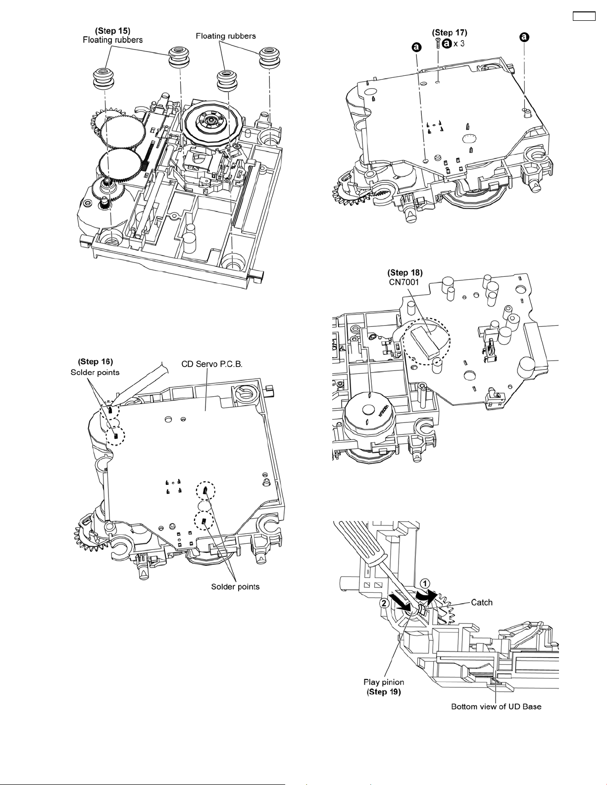
Step 17: Remove 3 screws.
CR14C
Step 15: Remove 4 floating rubbers.
• Disassembly of CD Servo P.C.B.
Step 18: Disconnect CN7001.
• Disassembly of Play Pinion
Step 16: Unsolder 4 solder points.
Step 19: Use a flathead screwdriver to release the catch and
push down play pinion as arrows shown.
39
Page 40
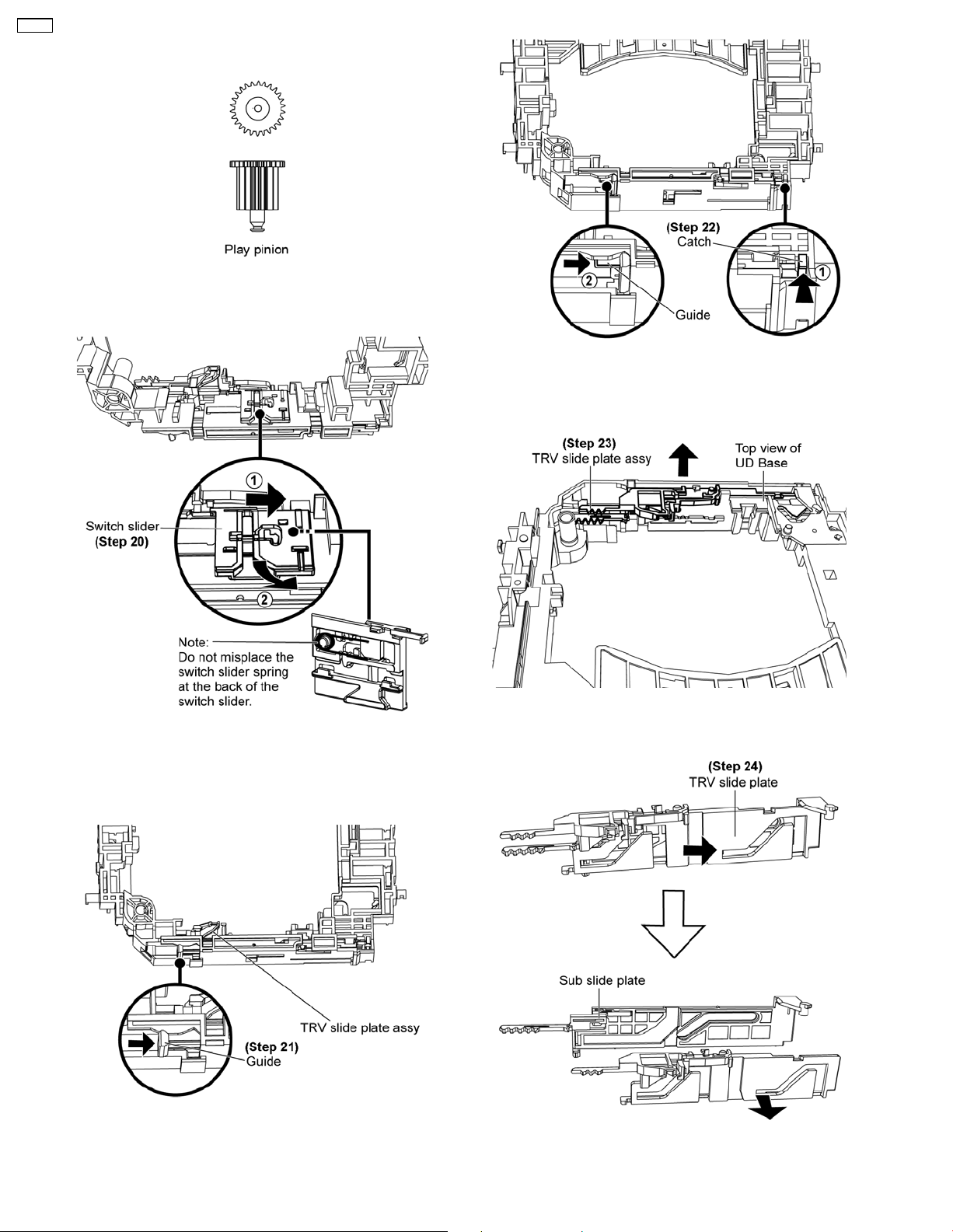
CR14C
• Illustration of the Play Pinion
• Disassembly of Switch Slider
Step 22: Release the catch and push the guide as arrows
shown.
Step 20: Push switch slider as direction shown until it stop and
remove it.
• Disassembly of TRV Slide Plate Assy
Step 21: Push the guide as arrow shown.
Step 23: Remove TRV slide plate assy.
Step 24: Slide the TRV slide plate as arrow shown then detach
the TRV slide plate from the sub slide plate.
40
Page 41
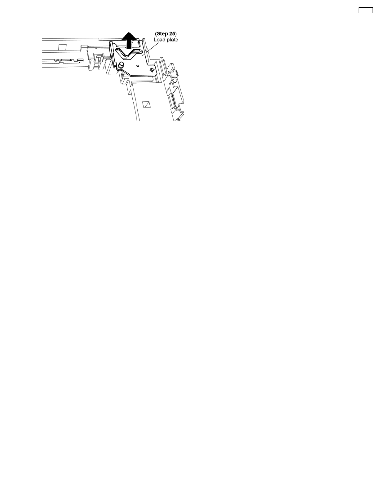
• Disassembly of Load Plate
Step 25: Position load plate as picture shown to remove it.
CR14C
41
Page 42
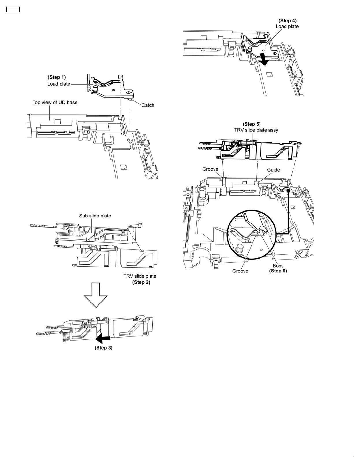
CR14C
10.3. Assembling of Mechanism
Unit
10.3.1. Assembly of UD Base Unit Parts
• Assembly of Load Plate
Step 4: Slide the load plate until it stop.
Step 1: Install load plate.
• Assembly of TRV Slide Plate Assy
Step 5: Install TRV slide plate assy align to groove and guide of
the UD base.
Step 6: Ensure the boss seated properly onto the groove.
Step 2: Attach the TRV slide plate to the sub slide plate.
Step 3: Slide the TRV slide plate until it stop.
42
Page 43
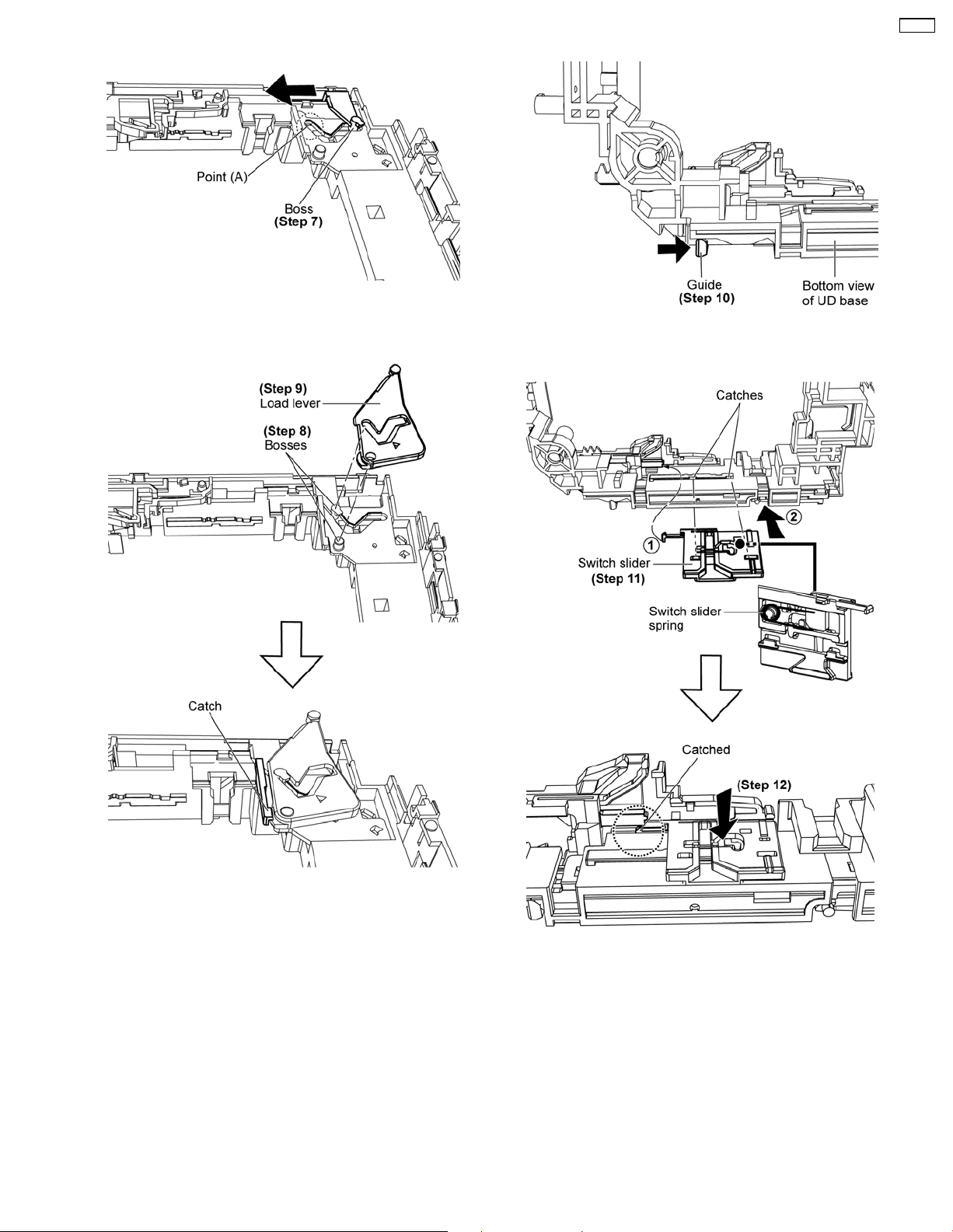
• Assembly of Load Lever
Step 7: Push as arrow shown to ensure the boss seated on
point (A).
CR14C
• Assembly of Switch Slider
Step 10: Push the guide until it stop.
Step 8: Ensure both bosses align.
Step 9: Install load lever as shown, make sure the catch is fully
catched.
Step 11: Fix the switch slider to the catches.
Note: Ensure the switch slider spring is fixed at the back of the
switch slider.
Step 12: Press down the switch slider and make sure it is fully
catched onto the UD base.
43
Page 44
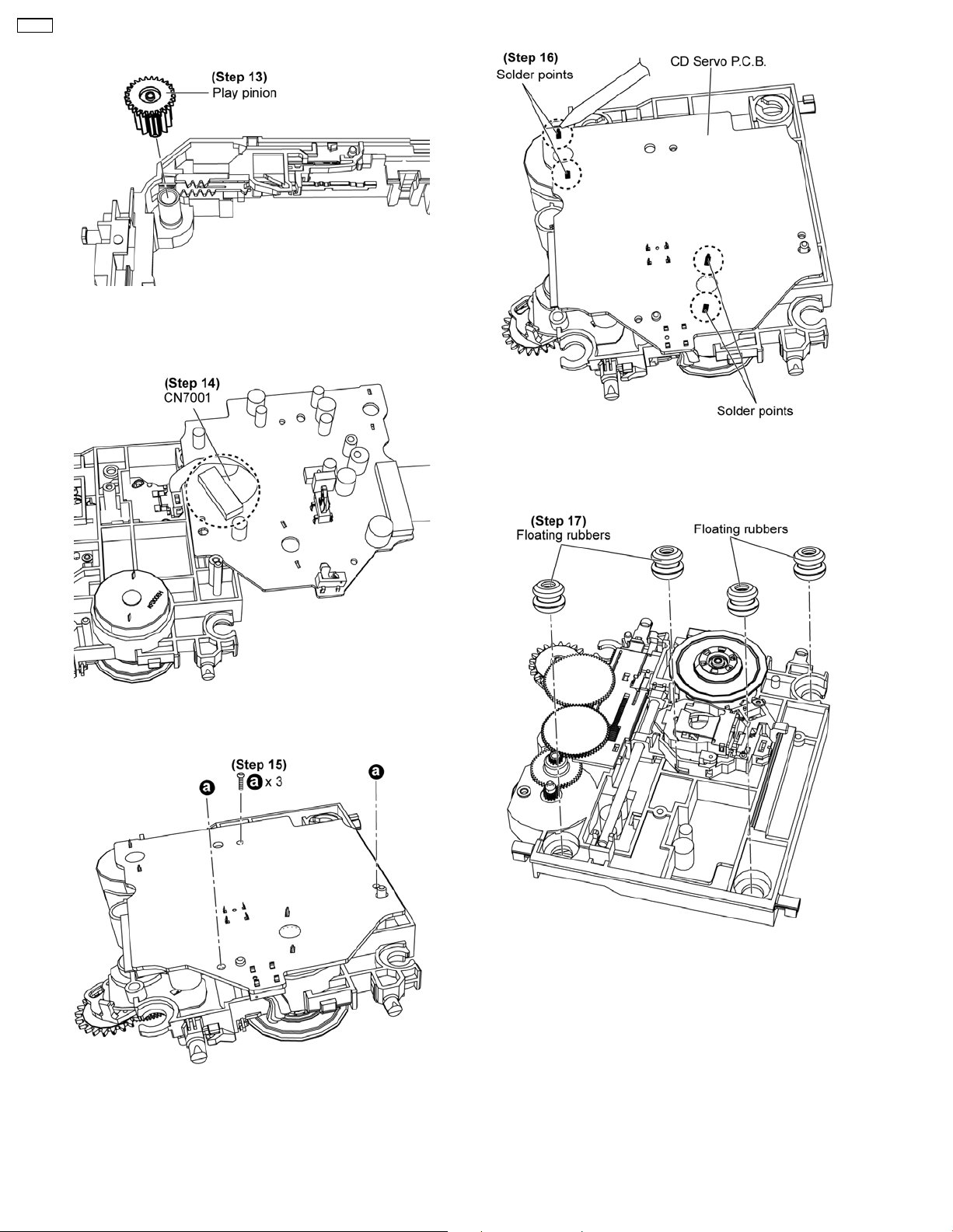
CR14C
• Assembly of Play Pinion
Step 13: Install the play pinion and press down.
• Assembly of CD Servo P.C.B.
Step 16: Solder 4 solder points.
Step 14: Connect CN700 1.
• Assembly of Traverse Unit
Step 15: Fix 3 screws.
Step 17: Fix 4 floating rubbers.
44
Page 45
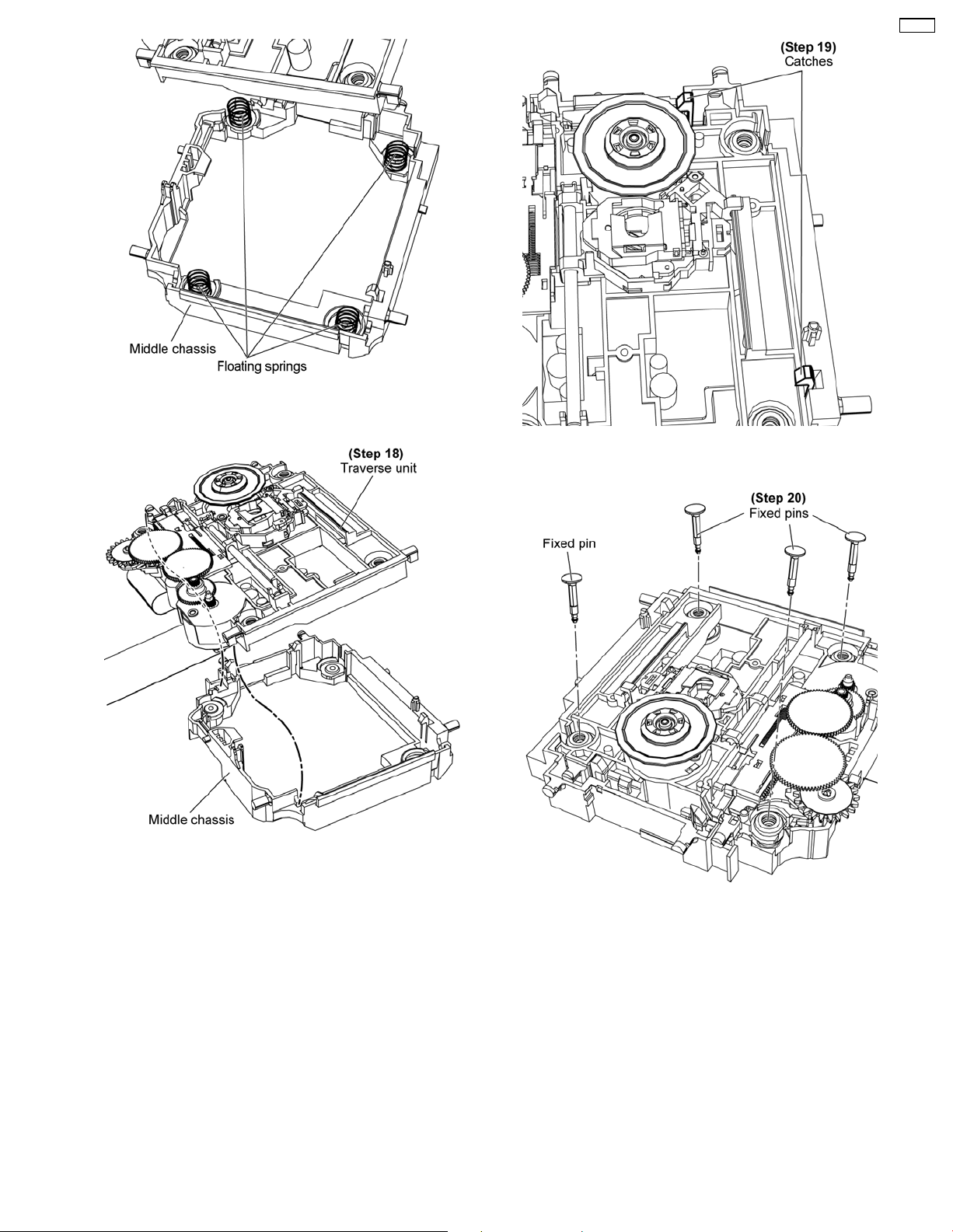
Note: Ensure 4 springs in place.
CR14C
Step 19: Ensure both catches are hooked.
Step 18: Tilt and slot the traverse unit onto the middle chassis.
Step 20: Fix 4 fixed pins.
45
Page 46
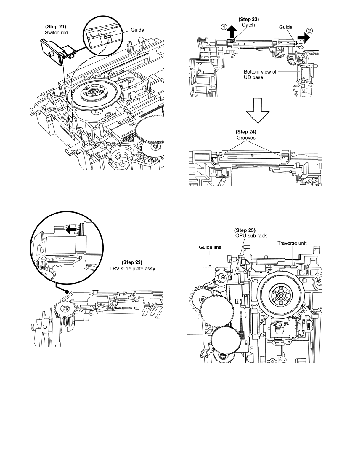
CR14C
Step 21: Fix switch rod, ensure the switch rod’s guide seat
properly onto the groove.
• Assembly of Traverse Unit Assy
Step 23: Turn over the UD base, release catch and push the
guide of the TRV slide plate as arrows shown.
Step 24: Ensure both grooves are open.
Step 22: Slide TRV slide plate assy to the end.
Step 25: Ensure the OPU sub rack is below the guide line.
46
Page 47
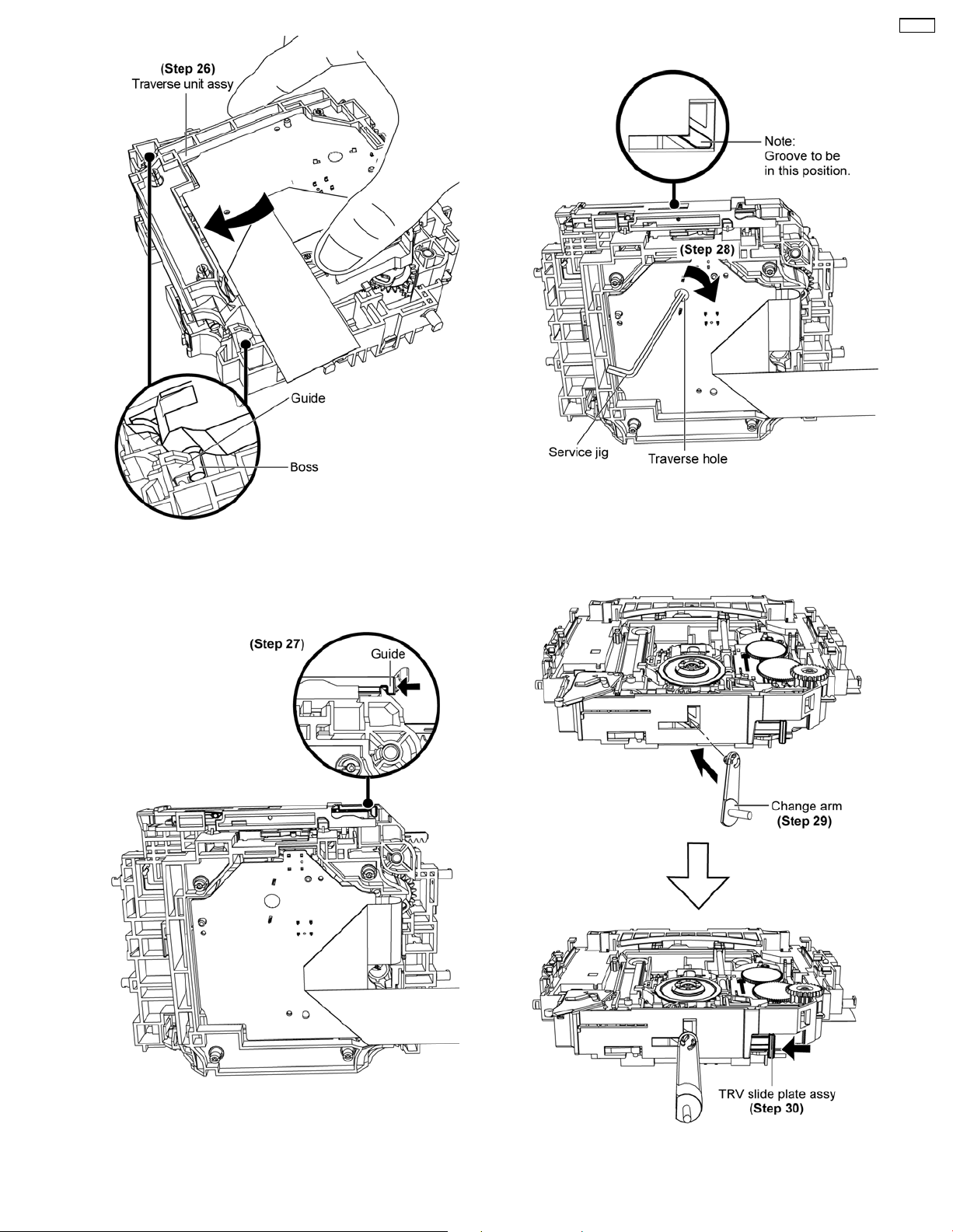
• Assembly of Change arm
CR14C
Step 26: Slot the traverse unit assy onto the UD base as arrow
shown.
Note: Ensure the bosses fix exactly onto the guides.
Step 28: Insert service jig into the traverse hole, rotate the gear
clockwise.
Note: Ensure the groove of the TRV slide plate assy stop at the
position shown.
Step 27: Push the guide to lock the traverse unit assy in.
Step 29: Install the change arm to the groove of the TRV slide
plate assy.
47
Page 48
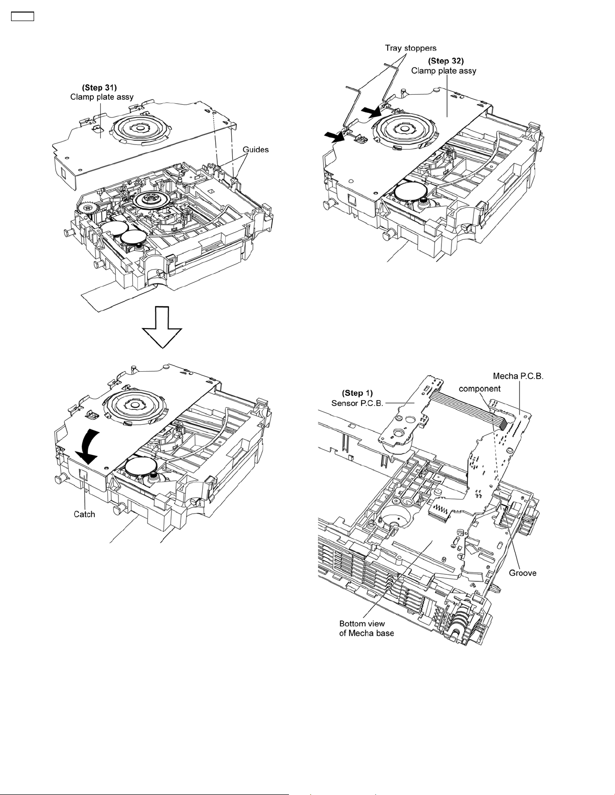
CR14C
Step 30: Push the TRV slide plate assy as arrow shown to lock
the change arm.
• Assembly of Clamp Plate Assy
• Assembly of Tray Stoppers
Step 32: Fix the tray stoppers.
Step 31: Fix the clamp plate assy align to both guides, make
sure the catch is fully catched.
10.3.2. Assembly of Mecha Base Unit
Parts
• Assembly of Mecha P.C.B. and Sensor P.C.B.
Step 1: Align the component of Mecha P.C.B. to the groove.
48
Page 49
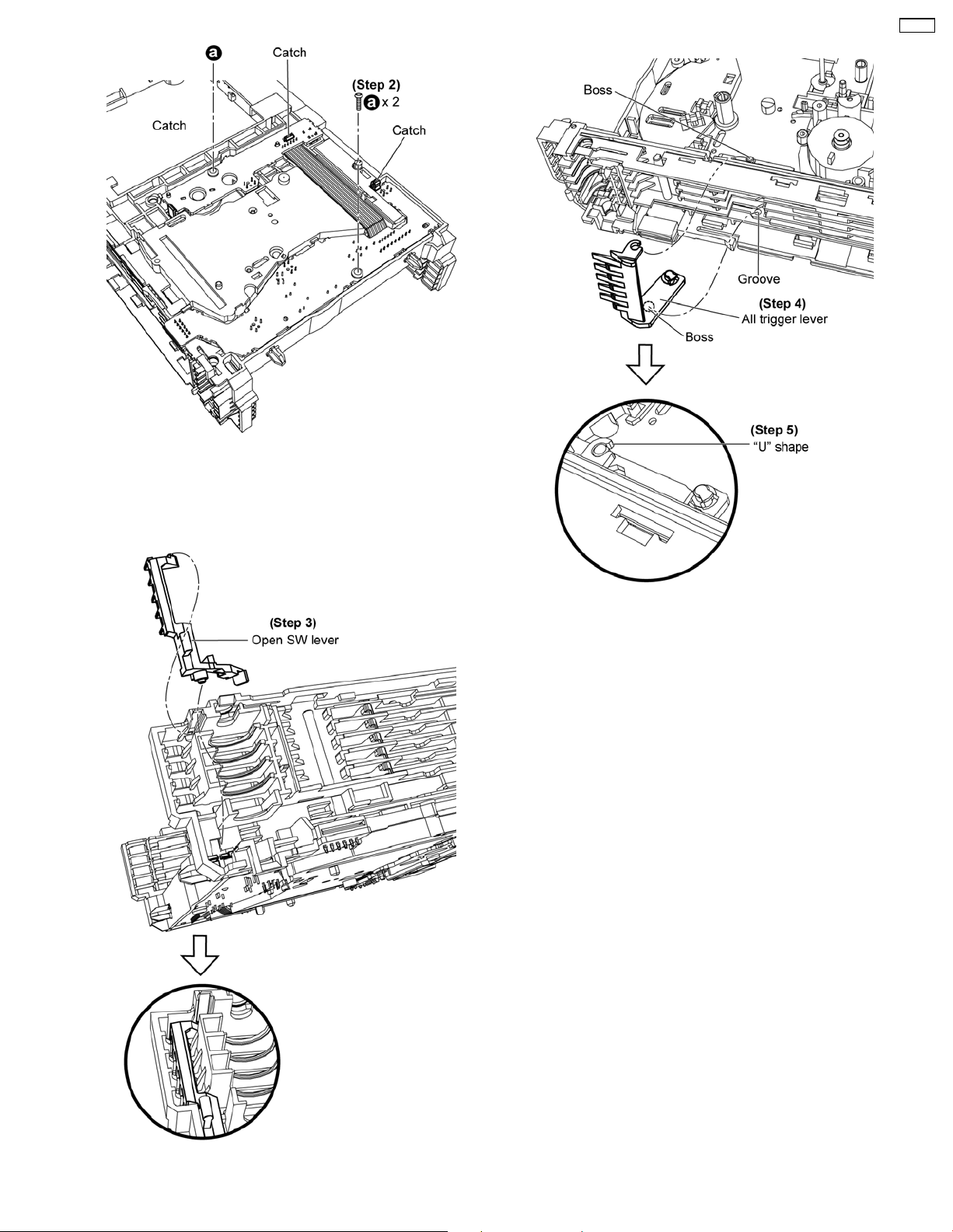
Step 2: Ensure all catches are hooked to the Mecha P.C.B. and
Sensor P.C.B. then fix 2 screws.
CR14C
• Assembly of All Trigger Lever
• Assembly of Open Switch Lever
Step 4: Ensure all trigger lever’s boss seated properly onto the
groove.
Step 5: Ensure the “U” shape of the all trigger lever snap to the
boss.
Step 3: Install open SW lever.
49
Page 50
CR14C
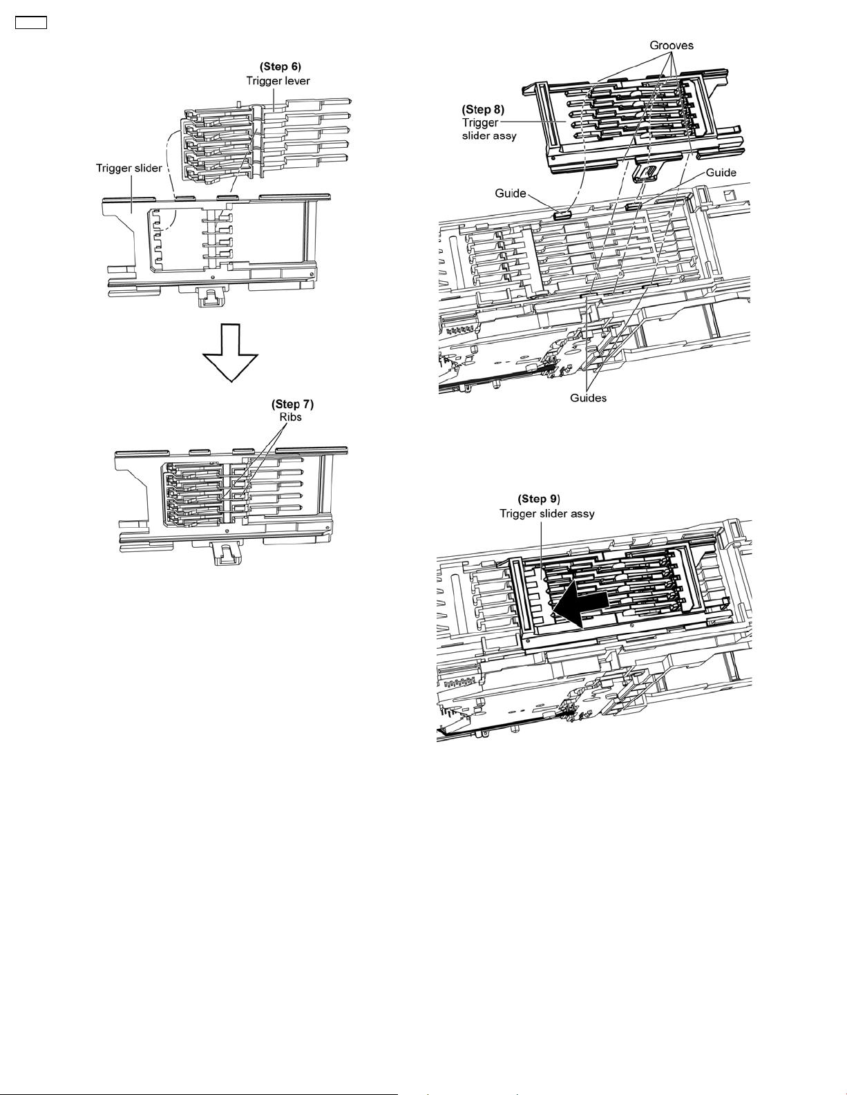
• Assembly of Trigger Slider Assy
Step 6: Combine both trigger slider and trigger lever.
Step 7: Ensure trigger lever’s ribs seated properly onto the
grooves.
Caution:
Do not exert force as it may cause damage to the trigger
lever.
Step 8: Install trigger slider assy, make sure the grooves fix
exactly onto the guides.
Step 9: Slide the trigger slider assy.
50
Page 51
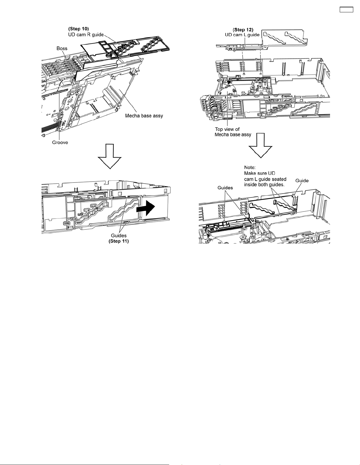
• Assembly of UD Cam R Guide
CR14C
• Assembly of UD Cam L Guide
Step 10: Insert the boss of the UD cam R guide onto mecha
base assy’s groove.
Step 11: Ensure UD cam R guide seated properly onto the
guides and slide as arrow shown.
Step 12: Install UD cam L guide align with all guides.
51
Page 52
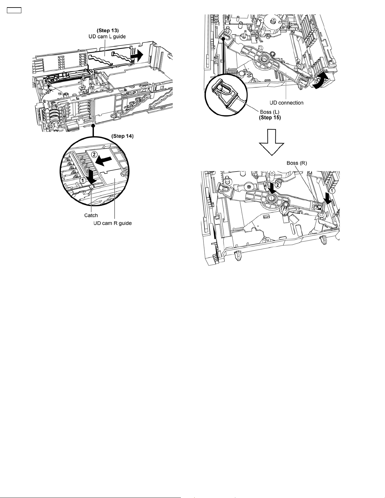
CR14C
• Assembly of UD Connection
Step 13: Slide the UD cam L guide until it stop as arrows
shown.
Step 14: Push the catch and slide the UD cam R guide as
arrows shown.
Step 15: Slot the UD connection onto the boss (L) and turn to
the direction as arrow shown to slot onto boss (R) to install it.
52
Page 53
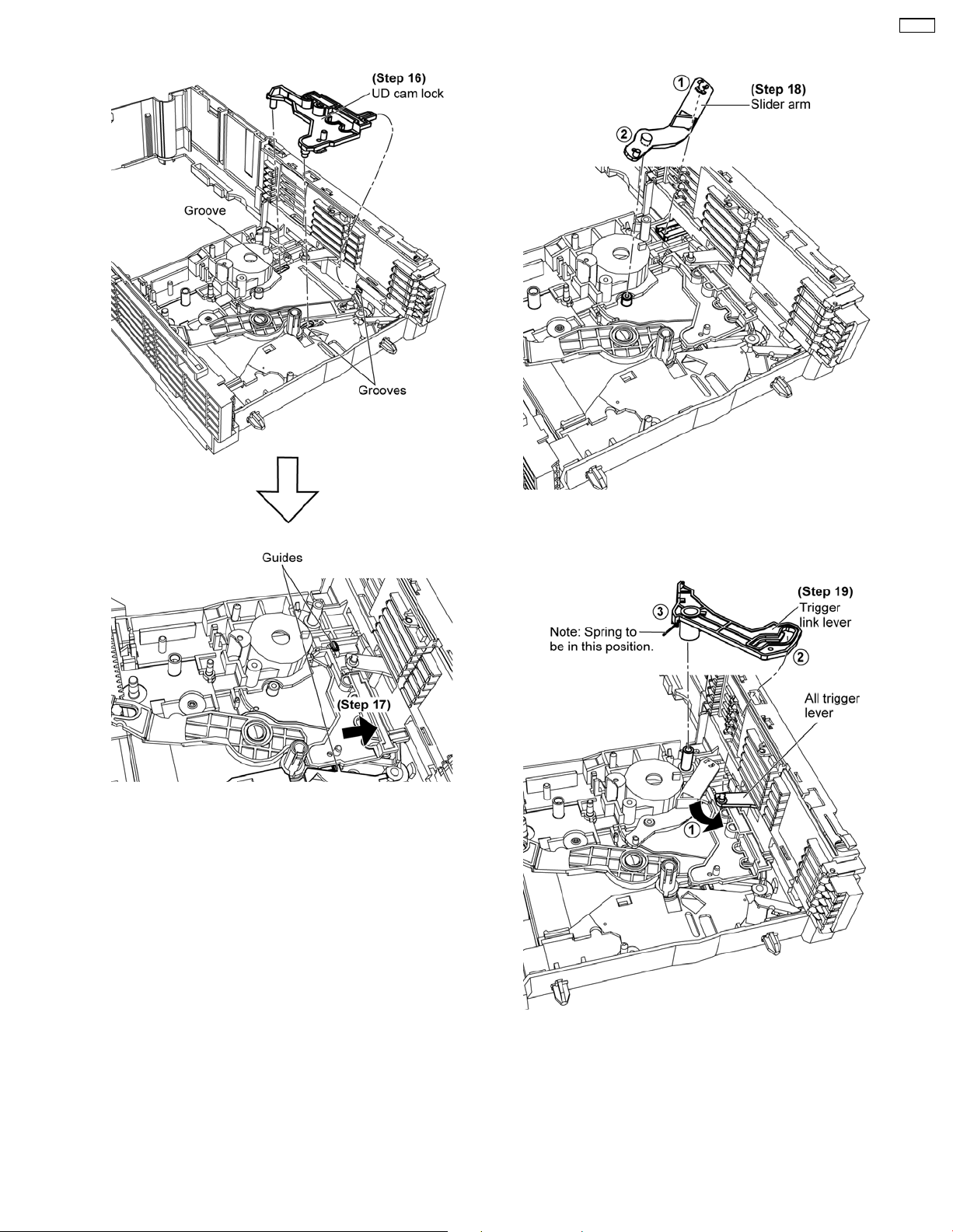
• Assembly of UD Cam Lock
CR14C
• Assembly of Slider Arm
Step 16: Slot cam lock onto the grooves.
Step 17: Move the UD cam lock as arrow shown, make sure the
UD came lock is underneath both guides.
Step 18: Install the slider arm.
• Assembly of Trigger Link Lever
Step 19: Slide and hold the all trigger lever as arrow shown
followed by Install the trigger link lever.
53
Page 54
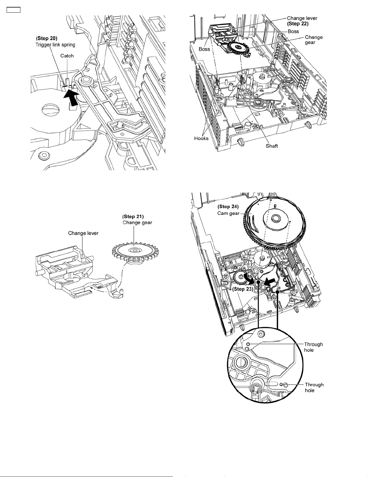
CR14C
Step 20: Make sure the trigger link spring is hooked underneath
the catch.
Step 22: Align change gear to the shaft and snap both bosses
of the change lever to the hooks.
• Assembly of Cam Gear
• Assembly of Change Lever and Change Gear
Step 21: Slot the change gear onto the change lever.
Step 23: Adjust both parts to align with the underneath holes.
Step 24: Align the holes and press down until it “click”.
54
Page 55
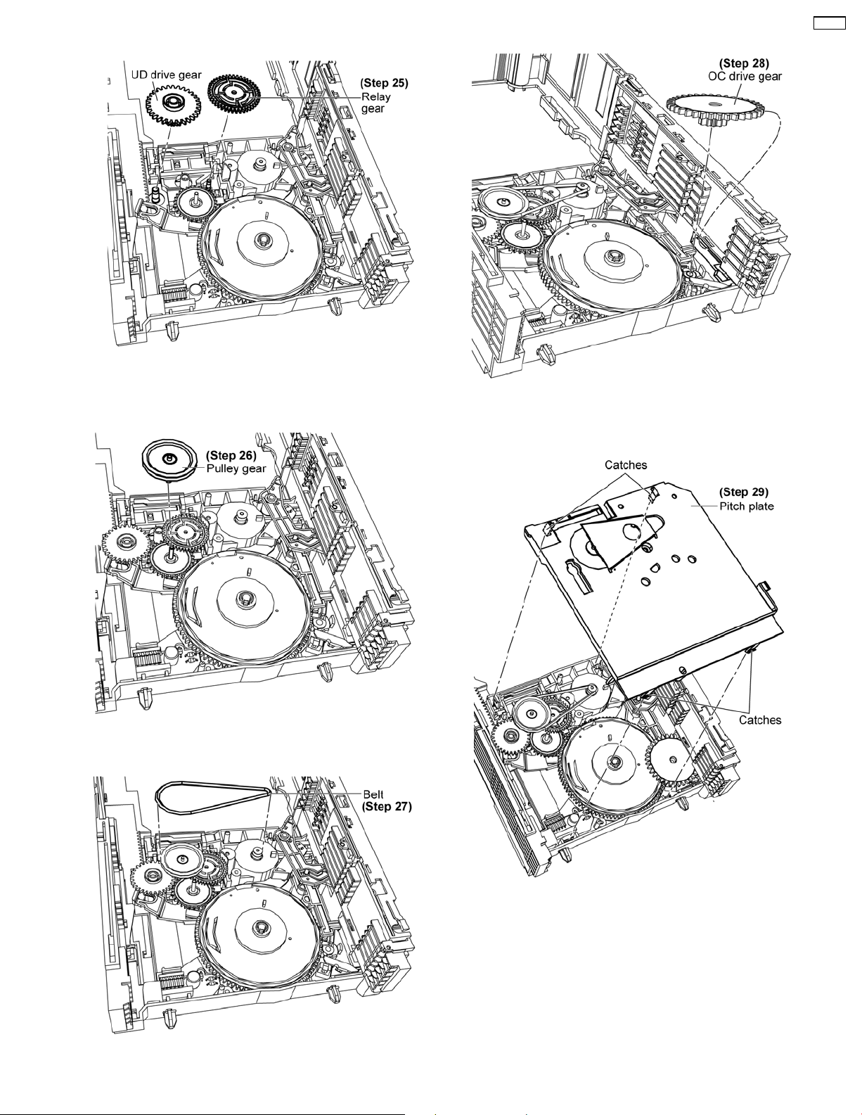
• Assembly of Relay Gear and UD Drive Gear
Step 25: Install relay gear and UD drive gear respectively.
• Assembly of Pulley Gear and Belt
CR14C
• Assembly of OC Drive Gear
Step 28: Install OC drive gear.
Step 26: Install pulley gear.
• Assembly of Pitch Plate
Step 27: Install belt.
Step 29: Install the pitch plate, ensure all the catches hooked
onto the mecha base assy.
55
Page 56
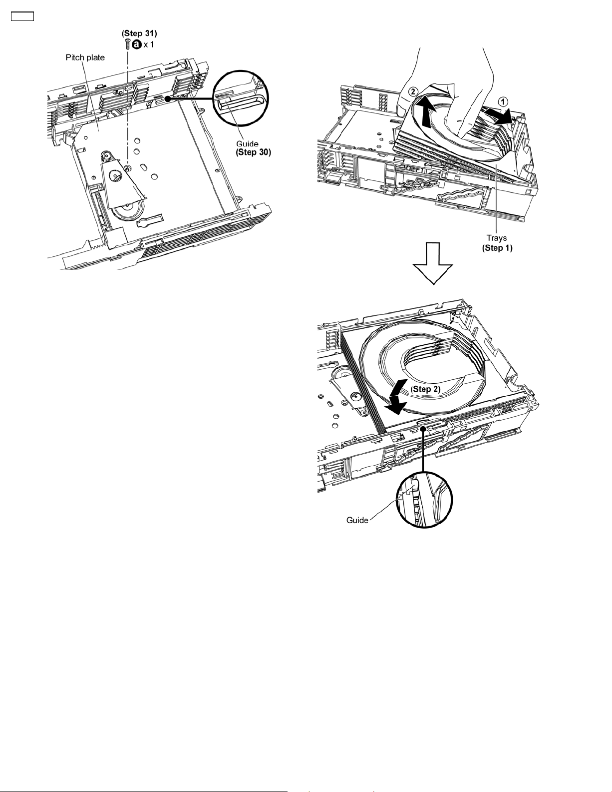
CR14C
Step 30: Ensure the guide is underneath the mecha base assy.
Step 31: Fix 1 screw.
10.3.3. Assembly of Trays
Step 1: Slot and tilt the trays as arrows shown.
Step 2: Place down the trays and position underneath their
respective guides.
56
Page 57
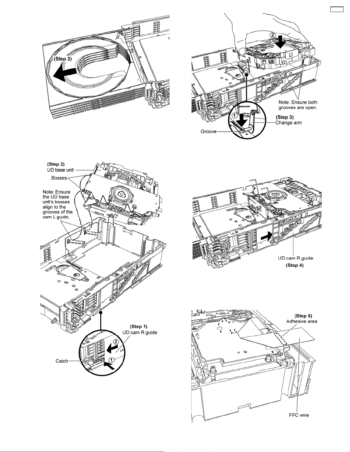
Step 3: Push the trays out.
CR14C
10.3.4. Assembly of UD Base Unit
Step 3: Ensure the change arm slot onto the groove then place
down the UD base unit into the open grooves.
Step 4: Slide the UD cam R guide as arrow shown to lock in the
UD base unit.
Step 1: Push the catch and slide the UD cam R guide as arrows
shown.
Step 2: Slot the UD base unit into the grooves.
Step 5: Turn over the set and fix the FFC wires by using the
57
Page 58
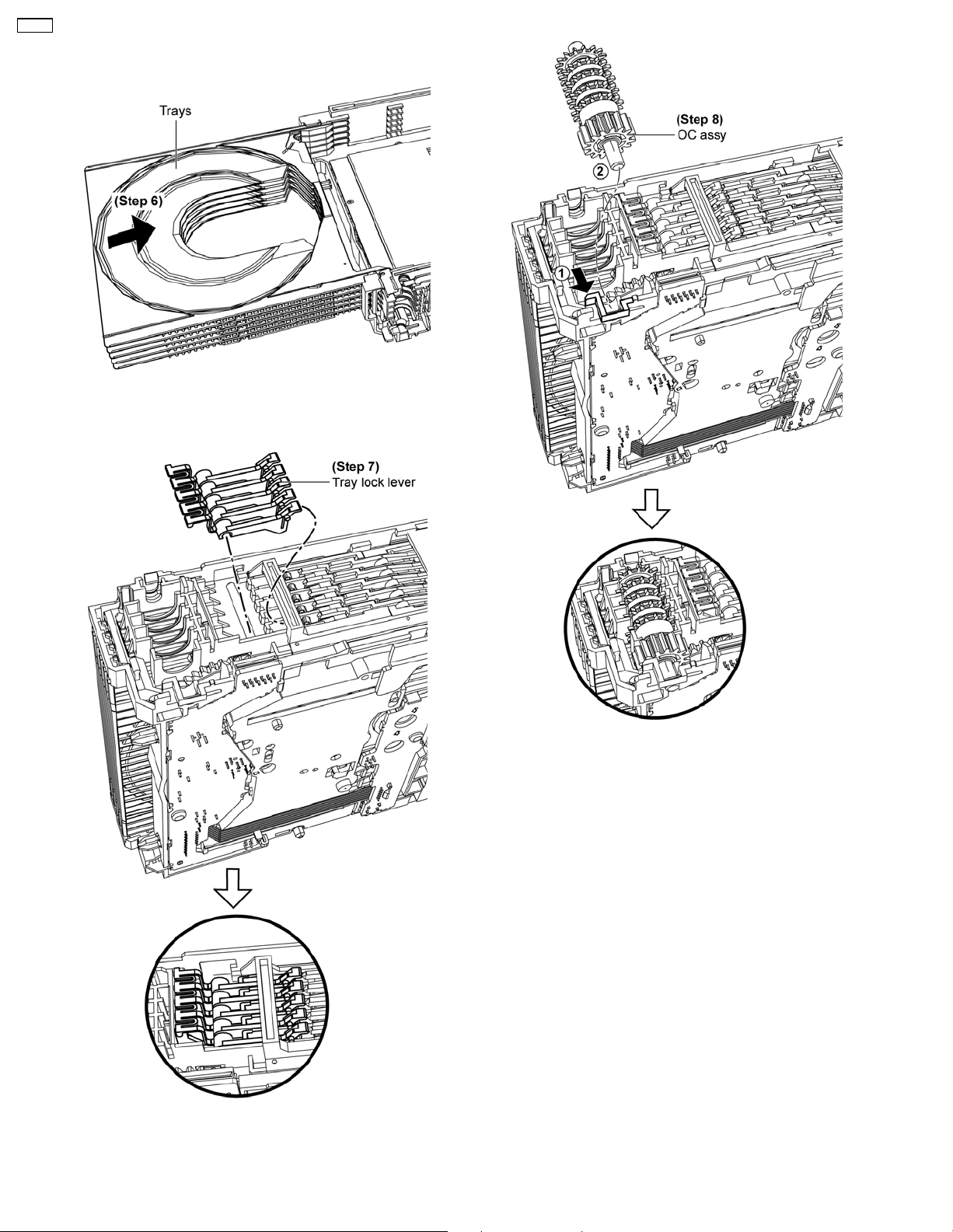
CR14C
adhesive tapes.
Step 6: Push in the trays.
Step 7: Install tray lock lever.
Step 8: Install OC assy.
58
Page 59
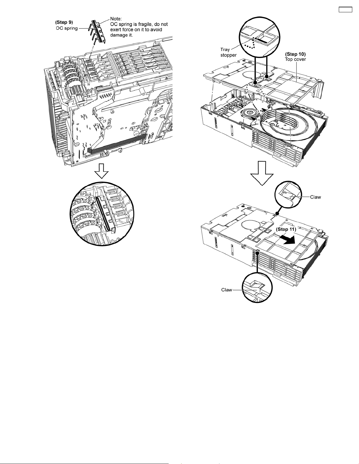
CR14C
Step 9: Install OC spring.
Step 10: Attach the top cover to the tray stoppers.
Step 11: Slide the top cover as arrow shown.
Note: Ensure both claws are catched.
59
Page 60

CR14C
60
Page 61
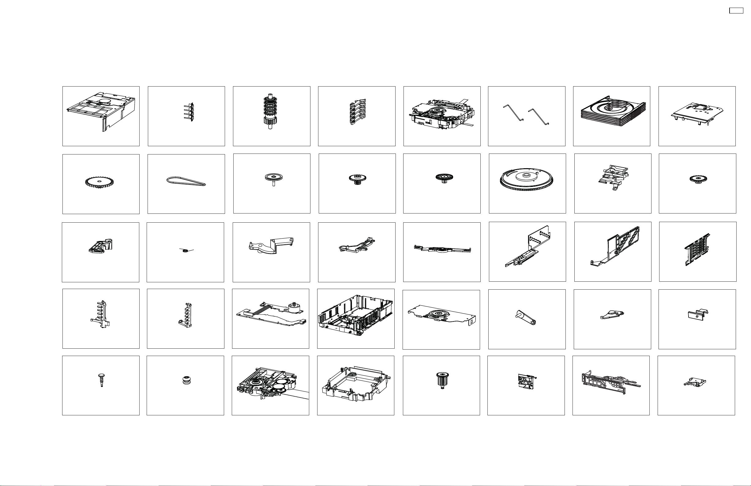
11 Disassembly Flow
CR14C
1. Top cover
9. OC drive gear
17. Trigger link lever
2. OC spring
10. Belt
18. Trigger link spring
3. OC assy
11. Pulley gear
19. Slider arm
4. Tray lock lever
12. UD drive gear
20. UD cam lock
5. UD base unit 6. Tray stoppers
13. Relay gear
21. UD connection
14. Cam gear
22. UD cam L guide
7. Trays
15. Change lever
23. UD cam R guide
8. Pitch plate
16. Change gear
24. Trigger slider assy
26. All trigger lever
34. Floating rubber
27. Mecha P.C.B. &
Sensor P.C.B.
35. Traverse unit
28. Mecha base assy25. Open SW lever
36. Middle chassis33. Fixed pin
29. Clamp plate assy
30. Change arm
38. Switch slider
31. Load lever
39. TRV slide plate assy
32. Switch rod
40. Load plate37. Play pinion
61
Page 62

CR14C
62
Page 63

12 Notes of Schematic Diagram
(All schematic diagrams may be modified at any time with
the development of new technology)
Note :
SW3 Top switch
• Importance safety notice :
Components identified by
characteristics important for safety.
Furthermore, special parts which have purposes of fireretardant (resistors), high-quality sound (capacitors), lownoise (resistors), etc. are used.
When replacing any of components, be sure to use only
manufacturer´s specified parts shown in the parts list.
• Resistor
Unit of resistance is OHM [Ω] (K=1,000,000).
• Capacitor
Unit of resistance is µF, unless otherwise noted. F=Farad,
pF=Pico-Farad
• *For Indication only.
mark have special
CR14C
• Voltage and Signal lines:
: +B Signal line
63
Page 64
CR14C
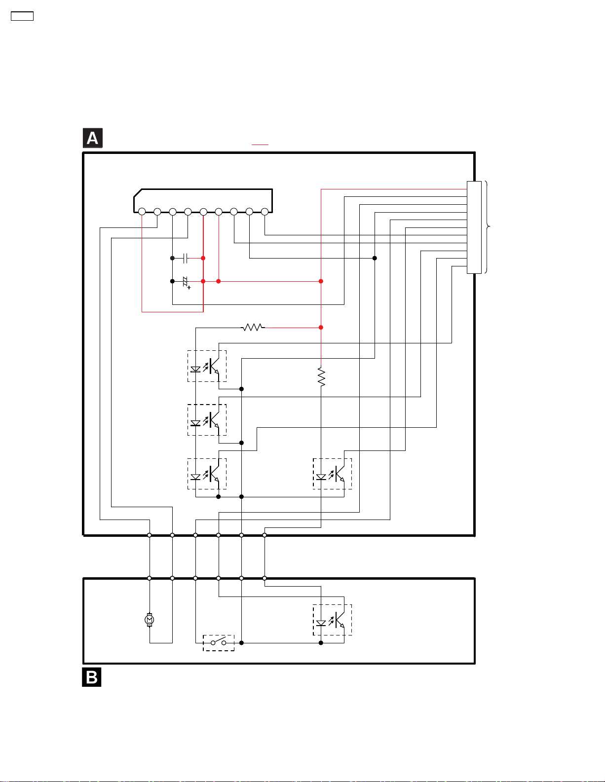
13 Schematic Diagram
13.1. Mecha Circuit & Sensor Circuit
6&+(0$7,&',$*5$0
0(&+$&,5&8,7
,&
&*$*
02725'5,9(5,&
287
4
4
51)
287
&
&
9
90
95()
%1$$
3+272,17(55837(5
23(16(1625
%1$$
3+272,17(55837(5
&/26(6(1625
%6,*1$//,1(
&1
9&&
3*1'
02'(
9&&
),1
*1'
5,1
5
5
'*1'
723
8'
/2)
/25
&/26(
+20(
23(1
720$,16(7
&,5&8,7
4
%1$$
3+272,17(55837(5
+20(6(1625
-
0
/2$',1*
6:
7236:,7&+
6(1625&,5&8,7
4
%1$$
3+272,17(55837(5
8'6(1625
02'(
6(1625
4
%1$$
3+272,17(55837(5
64
Page 65
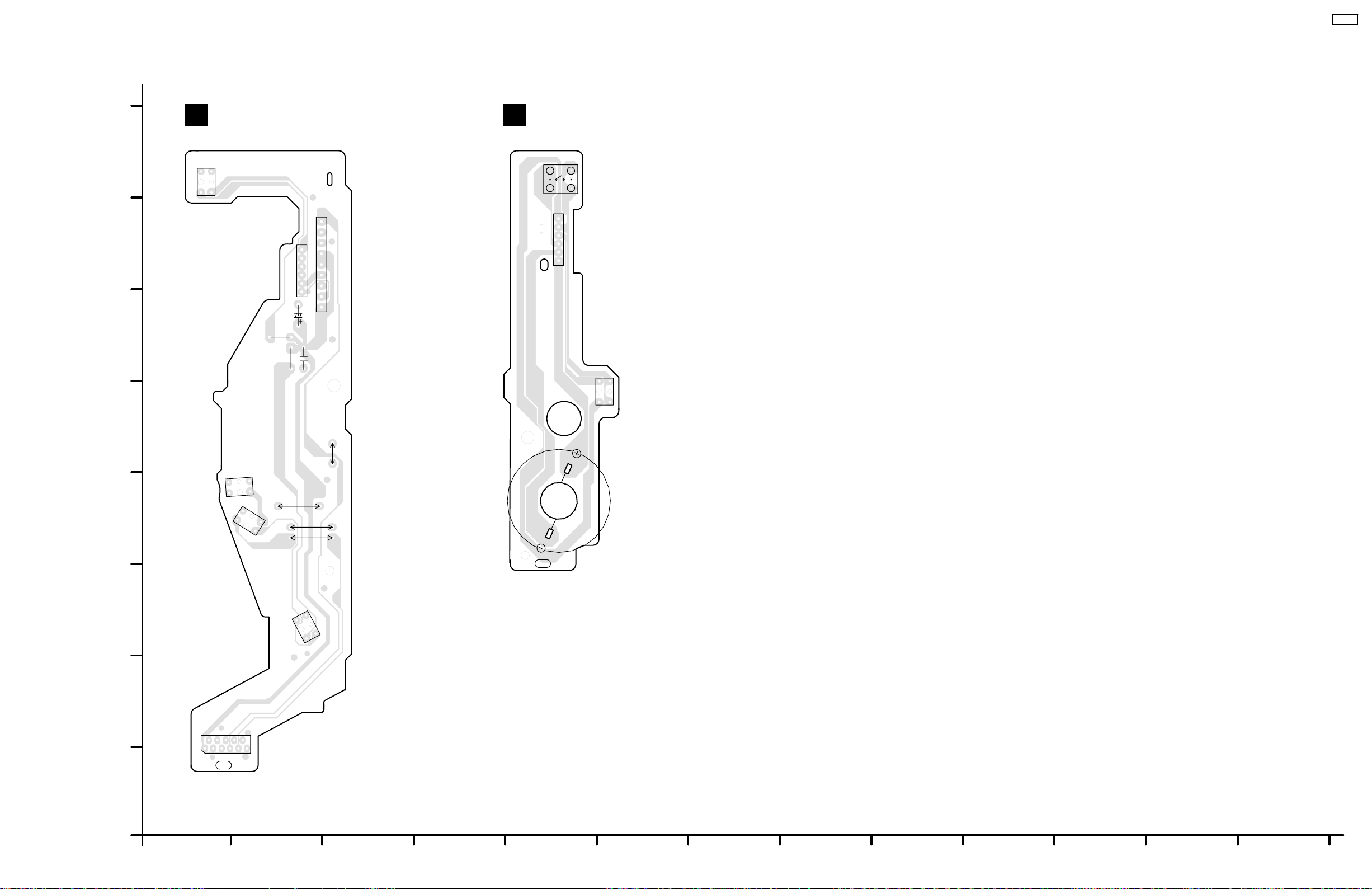
14 Printed Circuit Board
14.1. Mecha P.C.B. & Sensor P.C.B.
MECHA P.C.B. (REP4321A)
BA
SENSOR P.C.B. (REP4321A)
CR14C
H
G
F
E
Q1
Q3
SW3
341
(TOP SW)
2
IC1
9
8
J1
7
1
6
2
5
3
4
4
5
3
6
2
1
C2
R2
R1
C1
W4
J1
1
2
3
4
5
6
Q4
2
D
C
B
A
W3
Q5
CN2
1
2
(TO MAIN SET
CIRCUIT)
10
8
534769
3262A
PbF
3262A
Q2
11
* FOR INDICATION ONLY
M3*
(LOADING)
W2
W1
PbF
1
3262A
3262A
CR14
MECHA/ SENSOR P.C.B.
1
2
3
4
5
6
7
65
8
9
10 11 12 13
Page 66

CR14C
66
Page 67
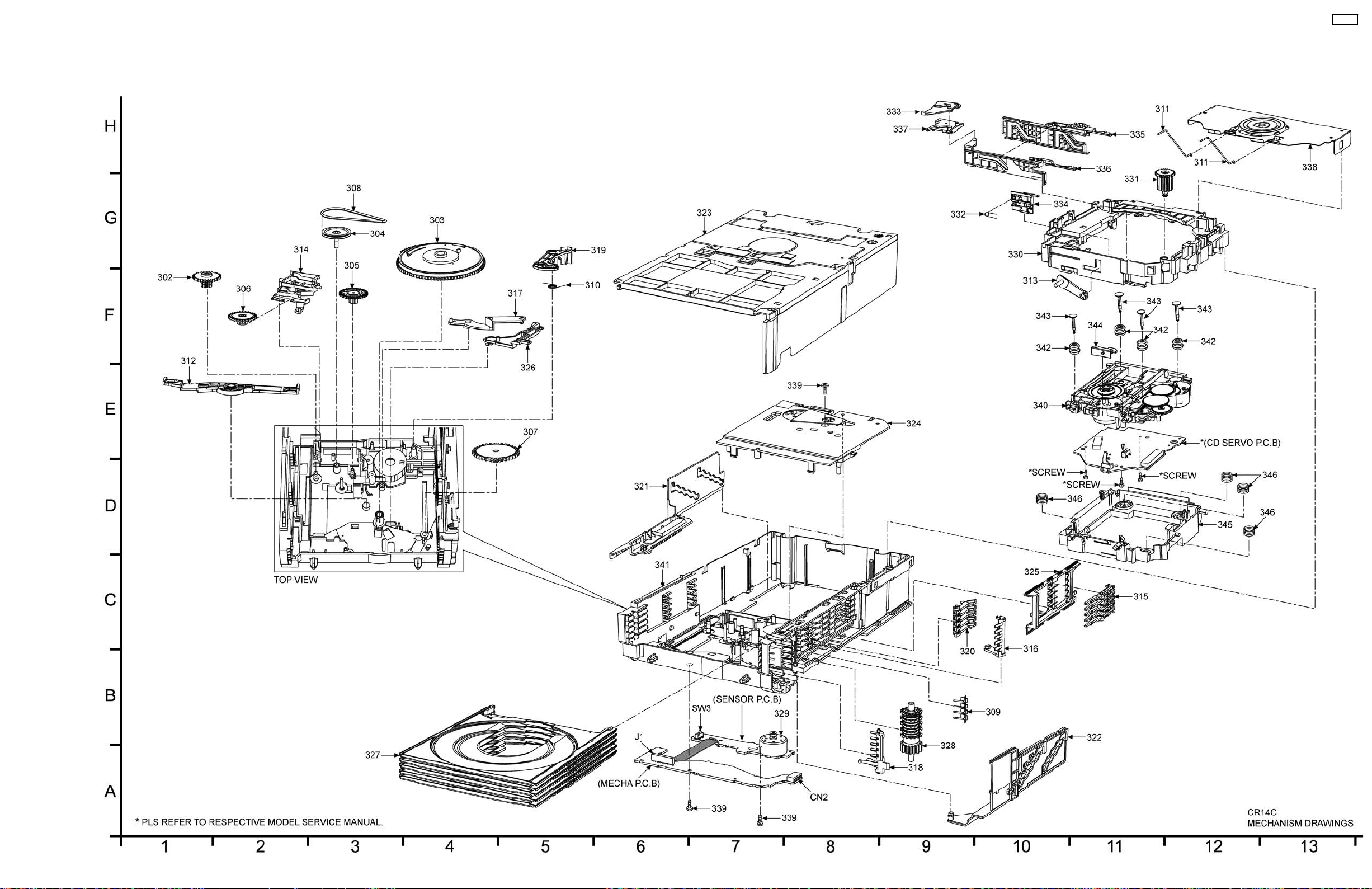
15 Exploded Views
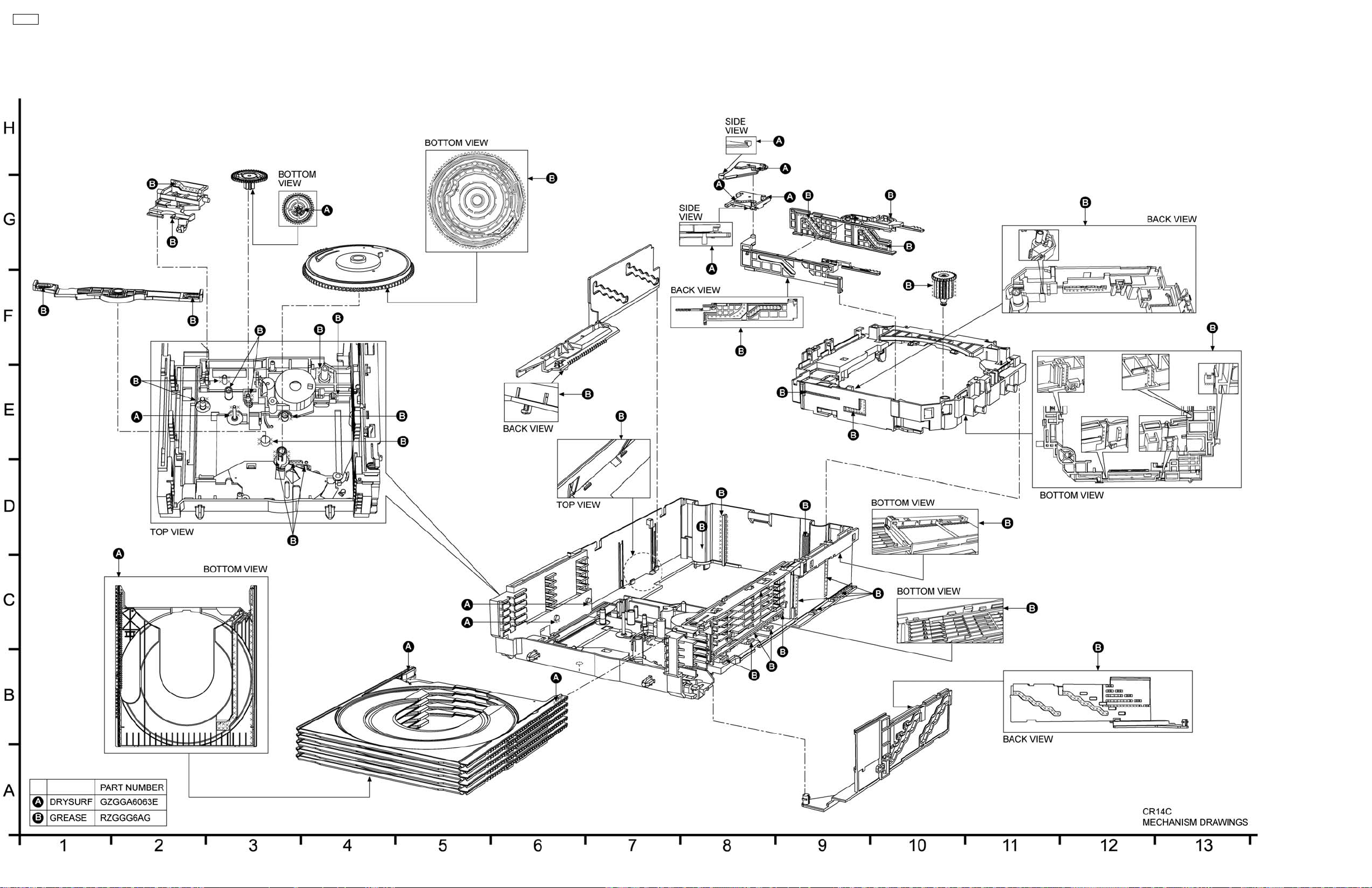
15.1. Cabinet Parts Location and Grease/Drysurf Location
CR14C
67
Page 68
CR14C
68
Page 69
16 Replacement Parts List
Notes:
• Important safety notice:
Components identified by
Furthermore, special parts which have purposes of fire-retardant (resistors), high-quality sound (capacitors), low-noise
(resistors), etc. are used.
When replacing any of these components, be sure to use only manufacturers’s specified parts shown in the parts list.
• Capacitor values are in microfarad (µF) unless specified otherwise, P=Pico-farads(pF); Farads.
• Resistance values are in ohms, unless specified otherwise, 1K=1,000(ohms).
• The marking (RTL) indicates that the Retention Time is limited for this item. After the discontinuation of this assembly in
production, the item will continue to be available for a specific period of time. The retention period of availability is dependant
on the type of assembly, and in accordance with the laws governing part and product retention. After the end of this period, the
assembly will no longer be available.
• [M] Indicates in the Remarks columns indicates parts that are supplied by PAVCSG.
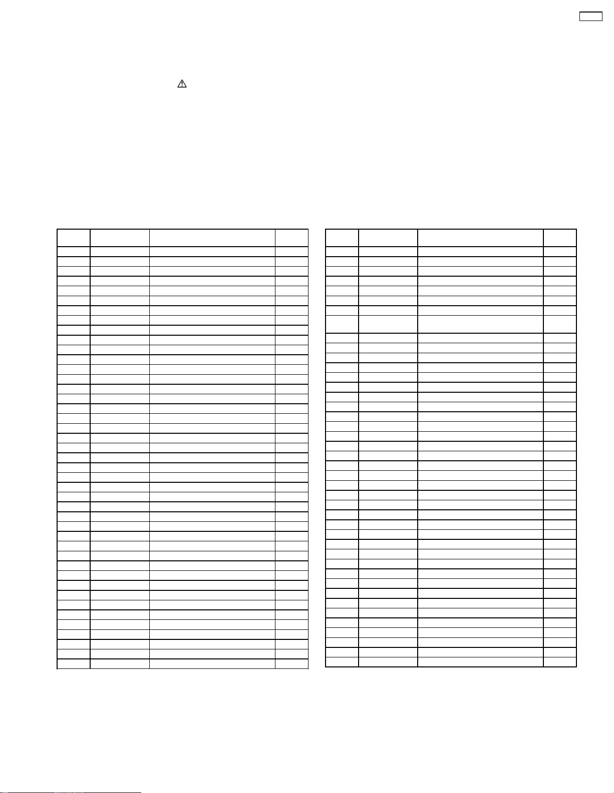
Ref.
No.
302 RDG0625 UD DRIVE GEAR [M]
303 RDG0626 CAM GEAR [M]
304 RDG0627 PULLEY GEAR [M]
305 RDG0628 RELAY GEAR [M]
306 RDG0629 CHANGE GEAR [M]
307 RDG0630 OC DRIVE GEAR [M]
308 RDV0078 BELT [M]
309 RMCX0031-1 OC SPRING [M]
310 RME0465 TRIGGER LINK SPRING [M]
311 RME0466 TRAY STOPPER [M]
312 RML0723 UD CONNECTION [M]
313 RML0724 CHANGE ARM [M]
314 RML0725 CHANGE LEVER [M]
315 RML0731 TRIGGER LEVER [M]
316 RML0732 ALL TRIGER LEVER [M]
317 RML0733-1 SLIDER ARM [M]
318 RML0734-1 OPEN SWITCH LEVER [M]
319 RML0735 TRIGGER LINK LEVER [M]
320 RML0736 TRAY LOCK LEVER [M]
321 RMM0293-1 UD CAM L [M]
322 RMM0294 UD CAM R [M]
323 RMQ1629 TOP COVER [M]
324 RMQ1632-1 PITCH PLATE [M]
325 RMQ1636 TRIGGER SLIDER [M]
326 RMQ1637 UD CAM LOCK [M]
327 RMR1857-H3 TRAY [M]
328 RXG0062 OC ASSY [M]
329 RXQ1568 MOTOR UNIT [M]
330 RFKJAPM670K1 UD BASE ASSY [M]
331 RDG0631 PLAY PINION [M]
332 RME0464 SWITCH SLIDER SPRING [M]
333 RML0726-1 LOAD LEVER [M]
334 RML0728-4 SWITCH SLIDER (GREY) [M]
335 RMM0295-2 TRV SLIDE PLATE [M]
336 RMM0296-1 SUB SLIDE PLATE [M]
337 RMQ1634 LOAD PLATE [M]
338 RXQ1571 CLAMP PLATE ASSY [M]
339 XTN26+6GFJ SCREW [M]
340 RAEX0190A-V TRAVERSE UNIT ASSY [M]
341 RFKJAPM670K2 MECHA BASE ASSY [M]
342 RMG0703-R FLOATING RUBBER [M]
Part No. Part Name & Description Remarks
CABINET & CHASSIS
Note:
• Models applied as below :SA-AK570PR/PL/GCP-K
SA-AK770EB/EG/GN/PR/PL/GCP-K
SA-AK870GCP/PR-K
SA-AK970GCP-K
mark have special characteristics important for safety.
Ref.
No.
343 RMS0757-1 FIXED PIN [M]
344 RML0737 SWITCH ROD [M]
345 RMQ1638 MIDDLE CHASSIS [M]
346 RME0109-1 SPRING [M]
PCB1 REP4321A MECHA PCB UNIT [M]
IC1 C0GAG0000007 IC MOTOR DRIVER [M]
Q1 B3NAA0000120 PHOTO INTERRUPTER [M]
Q2 B3NAA0000120 PHOTO INTERRUPTER [M]
Q3 B3NAA0000120 PHOTO INTERRUPTER [M]
Q4 B3NAA0000120 PHOTO INTERRUPTER [M]
Q5 B3NAA0000120 PHOTO INTERRUPTER [M]
CN2 K1MN11BA0004 11P CONNECTOR [M]
SW3 K0L1BA000134 TOP SWITCH [M]
J1 RWJ1106089XX 6P WIRE [M]
C1 F1D1E103A001 0.01 25V [M]
C2 F2A1C101A147 100 16V [M]
R1 D0AE181JA178 180 1/4W [M]
R2 D0AE241JA048 240 1/4W [M]
Part No. Part Name & Description Remarks
PRINTED CIRCUIT BOARD
(RTL)
INTEGRATED CIRCUIT
PHOTO INTERRUPTERS
CONNECTOR
SWITCH
WIRE
CAPACITORS
RESISTORS
CR14C
69
FLE0805
 Loading...