

Panasonic CJ-HDR216A, CJ-HDR416A Quick Start Manual

HD Analog Recorder
Quick Start Guide
Model No. CJ-HDR216A
CJ-HDR416A
Version 1.0.0

i
Table of Contents
1 Hardware Installation and Connection ..................................................................................... 1
1.1 Check Unpacked DVR .................................................................................................... 1
1.2 About the Panels and Cover ........................................................................................... 1
1.3 After Remove the Chassis............................................................................................... 1
1.4 HDD Installation............................................................................................................... 1
1.4.1 CJ-HDR216A ............................................................................................................ 1
1.4.2 CJ-HDR416A ............................................................................................................ 2
1.5 Rack Installation (CJ-HDR416A only) ............................................................................. 3
1.6 Front Panel ...................................................................................................................... 3
1.6.1 CJ-HDR216A ...................................................................................................... 3
1.6.2 CJ-HDR416A ...................................................................................................... 4
1.7 Rear Panel ....................................................................................................................... 6
1.8 Connection Sample ......................................................................................................... 9
1.9 Alarm Input and Output Connection .............................................................................. 10
1.9.1 Alarm Input and Output Details......................................................................... 10
1.9.2 Alarm Input Port ................................................................................................ 10
1.9.3 Alarm Output Port ............................................................................................. 11
2 Overview of Navigation and Controls ..................................................................................... 13
2.1 Boot up & Shut Down .................................................................................................... 13
2.1.1 Boot up .............................................................................................................. 13
2.1.2 Shut Down......................................................................................................... 13
2.1.3 Auto Resume after Power Failure .................................................................... 14
2.1.4 Replace Button Battery ..................................................................................... 14
2.2 Initial Settings ................................................................................................................ 14
2.2.1 Device Initialization ........................................................................................... 14
2.2.2 Reset Password ................................................................................................ 16
2.2.3 Startup Wizard .................................................................................................. 19
2.3 Preview .......................................................................................................................... 22
2.4 Manual Record .............................................................................................................. 24

ii
2.4.1 Record Operation .............................................................................................. 24
2.4.2 Snapshot Operation .......................................................................................... 24
2.5 Search & Playback ........................................................................................................ 25
2.5.1 Smart Search .................................................................................................... 30
2.5.2 Accurate Playback by Time .............................................................................. 31
2.5.3 Bookmark Playback .......................................................................................... 31
2.6 Schedule ........................................................................................................................ 33
2.6.1 Quick Setup ...................................................................................................... 35
2.6.2 Redundancy ...................................................................................................... 36
2.7 Snapshot ....................................................................................................................... 36
2.7.1 Schedule Snapshot ........................................................................................... 36
2.7.2 Trigger Snapshot .............................................................................................. 38
2.7.3 Priority ............................................................................................................... 40
2.7.4 Image FTP ........................................................................................................ 40
2.8 Network ......................................................................................................................... 41
2.9 Pan/Tilt/Zoom ................................................................................................................ 42
2.9.1 Pan/Tilt/Zoom Setup ......................................................................................... 42
2.9.2 Pan/Tilt/Zoom Operation ................................................................................... 43
3 Web Operation ........................................................................................................................ 45
3.1 Network Connection ...................................................................................................... 45
3.2 Device Initialization ........................................................................................................ 45
3.3 Login .............................................................................................................................. 47
3.4 Main Window ................................................................................................................. 48
3.4.1 LAN Login ......................................................................................................... 48
3.4.2 WAN Login ........................................................................................................ 48

iii
Welcome
Thank you for purchasing our HD Analog Recorder (DVR)!
This quick start guide will help you become familiar with our DVR in a very short time.
Before installation and operation please read the following safeguards and warnings carefully!

iv
Important Safeguards and Warnings
1.Electrical safety
All installation and operation here should conform to your local electrical safety codes.
The product must be grounded to reduce the risk of electric shock.
Please use three-pin power socket (with GND).
An apparatus with CLASS I construction shall be connected to a MAINS socket outlet with a
protective earthing connection.
Use a power supply which meets the requirements for SELV (Safety Extra Low Voltage) and
complies with Limited Power Source according to IEC 60950-1. Refer to the device label for
detailed information.
We assume no liability or responsibility for all the fires or electrical shock caused by improper
handling or installation.
2.Transportation security
Heavy stress, violent vibration or water splash are not allowed during transportation, storage and
installation.
3.Installation
Keep upwards. Handle with care.
Do not apply power to the DVR before completing installation.
Do not place objects on the DVR.
4.Qualified engineers needed
All the examination and repair work should be done by the qualified service engineers.
We are not liable for any problems caused by unauthorized modifications or attempted repair.
5.Environment
The DVR should be installed in a cool, dry place away from direct sunlight, inflammable,
explosive substances and etc.
6.Accessories
Be sure to use all the accessories recommended by manufacturer.
Before installation, please open the package and check all the components are included.
Contact your local retailer ASAP if something is broken in your package.
7.Lithium battery
Improper battery use may result in fire, explosion, or personal injury!
When replace the battery, please make sure you are using the same model!
RISK OF EXPLOSION IF BATTERY IS REPLACED BY AN INCORRECT TYPE.
DISPOSE OF USED BATTERIES ACCORDING TO THE INSTRUCTIONS.
1
1 Hardware Installation and Connection
Note: All the installation and operations here should conform to your local electrical safety rules.
1.1 Check Unpacked DVR
When you receive the DVR from the forwarding agent, please check whether there is any visible
damage. The protective materials used for the package of the DVR can protect most accidental
clashes during transportation. Then you can open the box to check the accessories.
Please check the items in accordance with the list. Finally you can remove the protective film of
the DVR.
1.2 About the Panels and Cover
For detailed information of the function keys in the front panel and the ports in the rear panel,
please refer to the User’s Manual included in the resource CD.
The model label in the front panel is very important; please check according to your purchase
order.
The label in the top cover is very important too. Usually we need you to represent the serial
number when we provide the service after sales.
1.3 After Remove the Chassis
Please check the data cable, power cable, COM cable and main board cable connection is
secure or not.
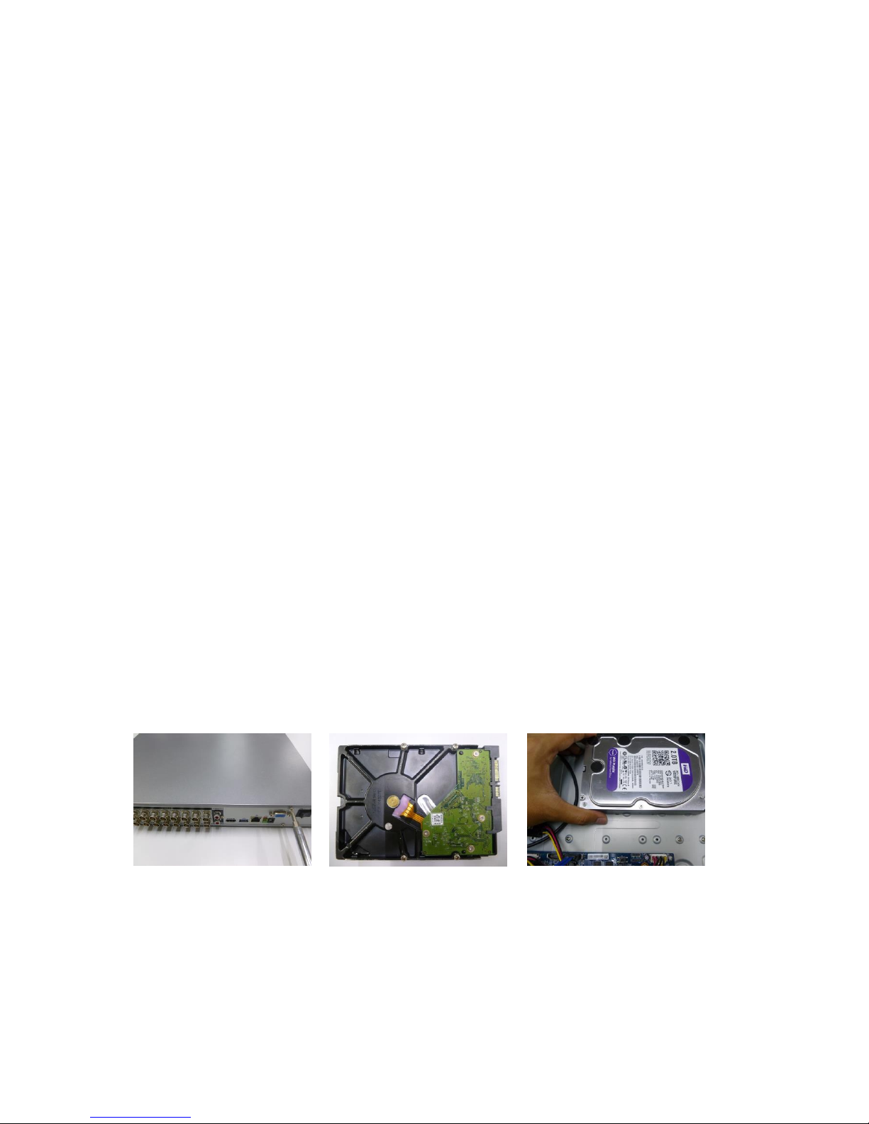
1.4 HDD Installation
Please use HDD of 7200rpm or higher.
1.4.1 CJ-HDR216A
This DVR has two SATA HDDs.
① Loosen the screws of the
upper cover.
② Fix four screws in the HDD
(Turn just three rounds).
③ Place the HDD in accordance
with the four holes at the bottom.
2
④ Turn the device upside down
and then turn the screws in firmly.
⑤ Fix the HDD firmly.
⑥ Connect the HDD cable and
power cable.
⑦ Put the cover in accordance
with the clip and then place the
upper cover back.
⑧ Secure the screws in the rear
panel.
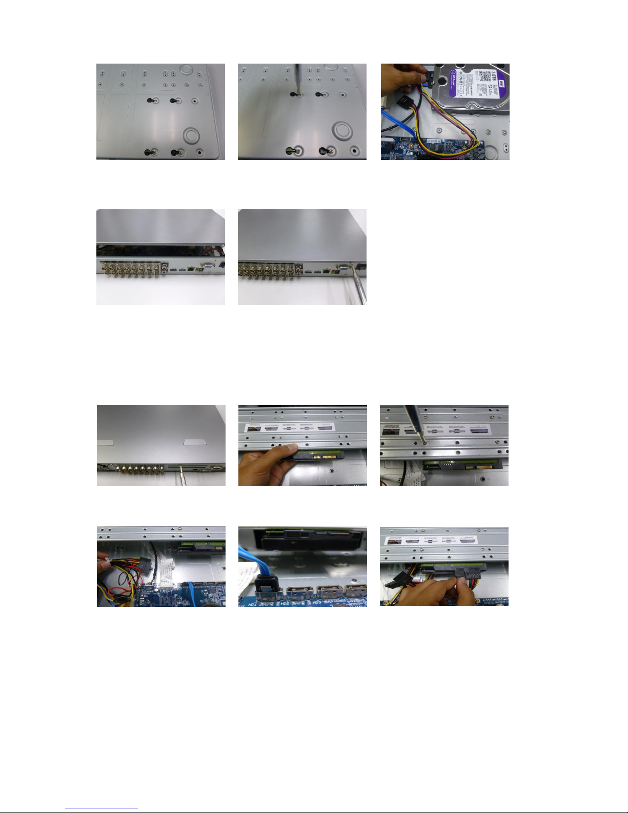
1.4.2 CJ-HDR416A
This DVR max has four SATA HDDs.
① Loosen the screws of the
upper cover.
② Line up the HDD to the four
holes of the HDD bracket.
③ Use four screws to fix HDD.
④ Unfasten the HDD power
cable.
⑤ Use the special data cable to
connect the HDD and the SATA
port.
⑥ Insert the HDD power cable.
Close the chassis and fix the
screws to secure firmly.
Important
You can connect the HDD data cable and the power cable first and then fix the HDD in the
device.
Please pay attention to the front cover. It adopts the vertical sliding design. You need to push
the clip first and then put down.
3
1.5 Rack Installation (CJ-HDR416A only)
The DVR occupies 1.5U rack units of vertical rack space.
Use twelve screws to fix the unit.
Please make sure the indoor temperature is below 35°C (95°F).
Please make sure there is 15cm (6 inches) space around the device to guarantee sound
ventilation.
Please install from the bottom to the top.
If there are more accessories connected in the rack, please take precaution measures in case
the rack power is overload.
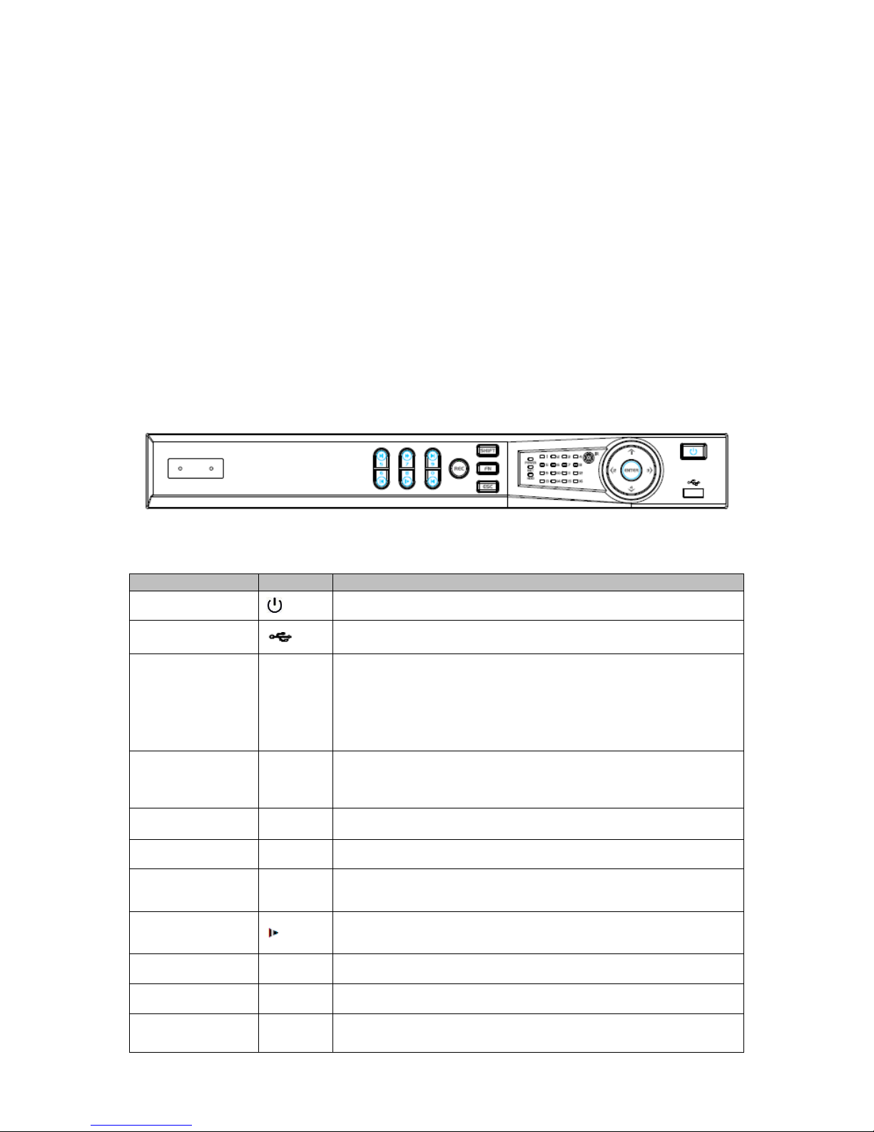
1.6 Front Panel
1.6.1 CJ-HDR216A
The front panel is shown as below. See Figure 1-1.
Figure 1-1
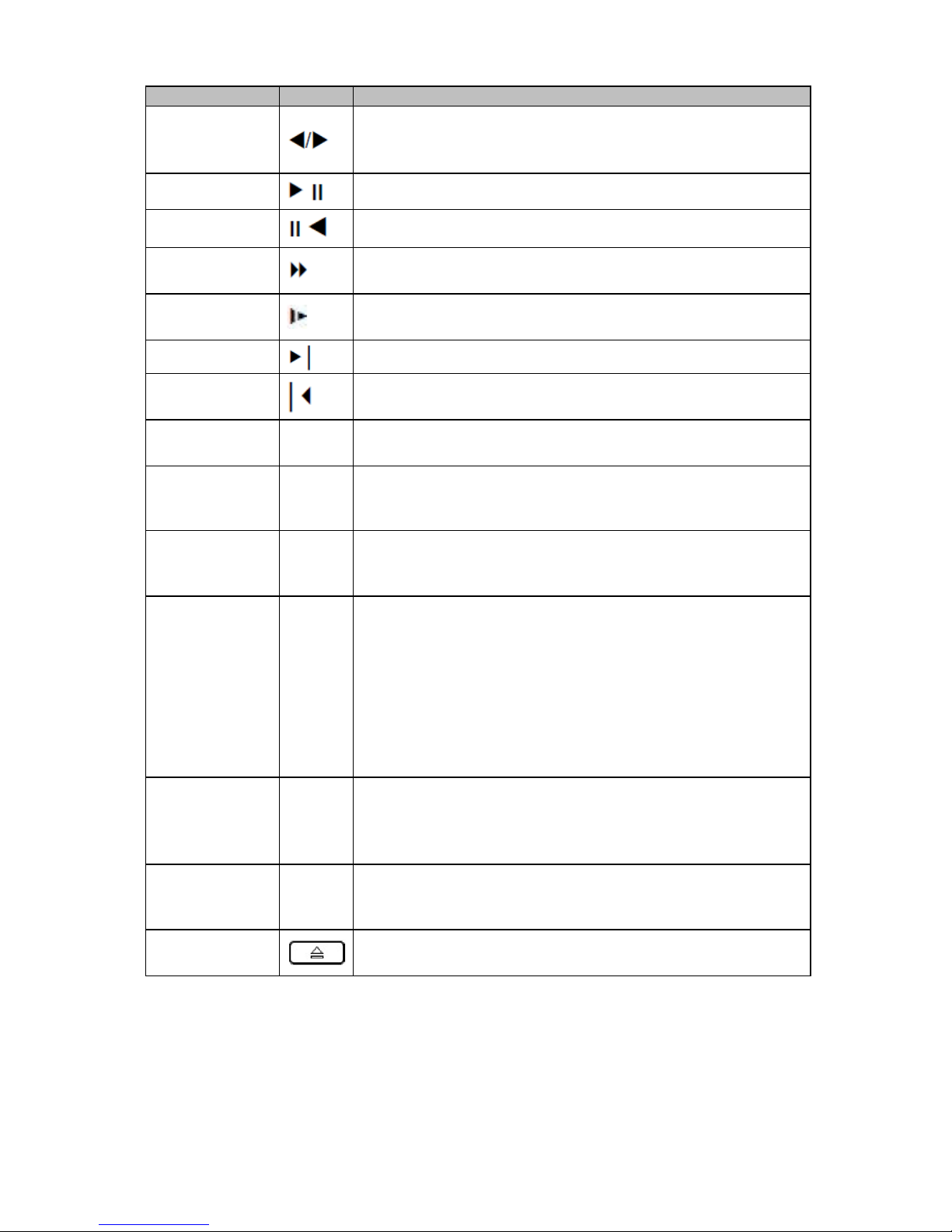
Please refer to the following sheet for front panel button information.
Name
Icon
Function
Power button
Press this button to boot up or shut down the device.
USB port
Connect to USB2.0 storage device, mouse and etc.
Up/1
Down/4
/
Activate current controls, and then move up, move down or
jump.
Change setup, increase/decrease numeral.
Assistant function such as PTZ menu.
Switch channel when playback.
Left/2
Right/3
/
Switch current activated controls, move up and down.
When device is in 1-channel playback mode, use it to control
playback control bar process.
Play/Pause/5
When playback, click it to pause, click it again to play again.
Reverse/Pause/6
When playback, click it to begin reverse play.
Fast forward/7
When playback, it supports various fast forward speeds and
normal playback.
Slow playback/8
When playback, it supports various slow playback speeds and
normal playback.
Play next /9
│
When playback, click it to view the next record.
Play previous/0
│
When playback, click it to view the previous record.
Record indicator
1~16
It is to display system is recording or not.
The light becomes on when system is recording.
4
Name
Icon
Function
Cancel
ESC
Go to previous menu, or cancel current operation (Close the
top interface or controls).
When playback, click it to restore real-time monitor mode.
Confirm
ENTER
Confirm current operation.
Go to default button.
Go to the menu.
Assistant
FN
One-window monitor mode, click this button to display
assistant function: PTZ control and image color.
In menu control interface click to switch PTZ control menu.
In motion detection setup, working with FN and direction
keys to realize setup.
Backspace function: in numeral control or text control, press
it for 1.5 seconds to delete the previous character before the
cursor.
Realize other special functions.
Shift
SHIFT
In textbox, click it to switch between numeral, English
character (small/capitalized) and etc.
Record
REC
It is to start/stop record manually.
In record control interface, working with the direction buttons
to select the record channel.
Power indicator
POWER
Light turns on when power connection is OK.
Network indicator
NET
Light turns on when network connection is abnormal.
HDD indicator
HDD
Light turns on when HDD is abnormal.
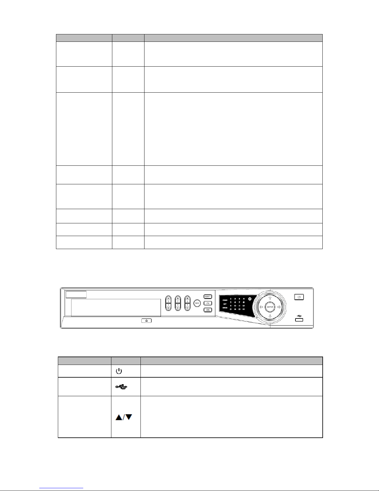
1.6.2 CJ-HDR416A
The front panel is shown as below. See Figure 1-2.
Figure 1-2
Please refer to the following sheet for front panel button information.
Name
Icon
Function
Power button
Press this button to boot up or shut down the device.
USB port
Connect to USB2.0 storage device, mouse, DVD burner and etc.
Up/1
Down/4
Activate current controls, and then move up, move down or
jump.
Change setup, increase/decrease numeral.
Assistant function such as PTZ menu.
Switch channel when playback.
5
Name
Icon
Function
Left/2
Right/3
Switch current activated controls, move up and down.
When device is in 1-channel playback mode, use it to control
playback control bar process.
Play/Pause/6
When playback, click it to pause, click it again to play again.
Reverse/Pause/5
When playback, click it to begin reverse play.
Fast forward/7
When playback, it support various fast forward speeds and
normal playback.
Slow playback/8
When playback, it support various slow playback speeds and
normal playback.
Play next/0
When playback, click it to view the next record.
Play previous/9
When playback, click it to view the previous record.
Record indicator
light
1 ~ 16
It is to display system is recording or not.
The light becomes on when system is recording.
Cancel
ESC
Go to previous menu, or cancel current operation (Close the
top interface or controls).
When playback, click it to restore real-time monitor mode.
Confirm
ENTER
Confirm current operation.
Go to default button.
Go to the menu.
Assistant
FN
One-window monitor mode, click this button to display
assistant function: PTZ control and image color.
In menu control interface, click to switch PTZ control menu.
In motion detection setup, working with FN and direction keys
to realize setup.
Backspace function: in numeral control or text control, press it
for 1.5 seconds to delete the previous character before the
cursor.
Realize other special functions.
Shift
SHIFT
In text mode, click it to switch between numeral, English
character (small/capitalized) and etc.
During tour process, click it to enable/disable tour function.
Click it to auto adjust resolution when device boots up.
Record
REC
It is to start/stop record manually.
In record control interface, working with the direction buttons
to select the record channel.
CDROM
This button is inapplicable. Please do not press it with too much
force.
6
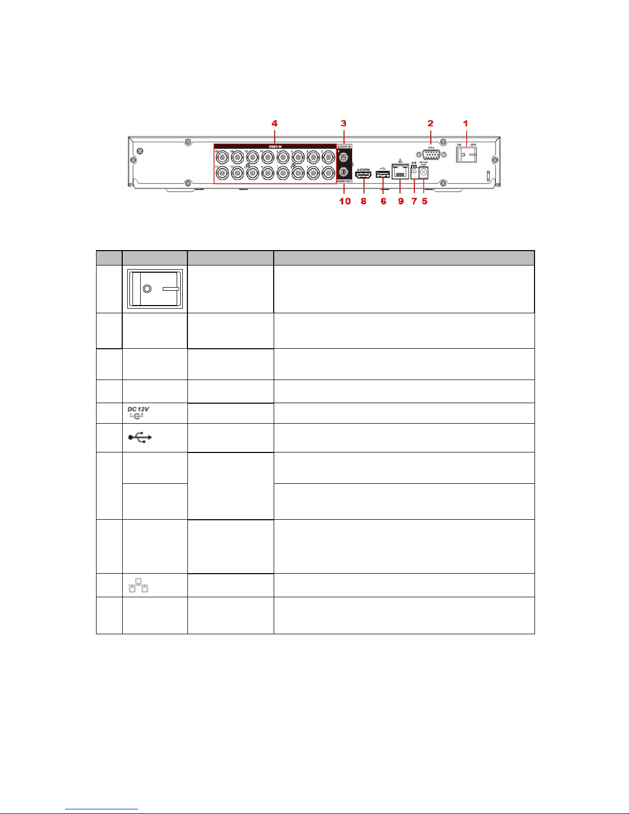
1.7 Rear Panel
Rear panel of CJ-HDR216A is shown as below. See Figure 1-3.
Figure 1-3
Please refer to the following sheet for detailed information.
SN
Icon
Name
Note
1 Power switch
Power on/off button.
2
VGA
VGA video
output port
VGA video output port. Output analog video signal. Can
connect to the monitor to view analog video output.
3
AUDIO IN
Audio input port
Connect to audio input device such as microphone or
other audio input device.
4
VIDEO IN
Video input port
Connect to analog camera, video input signal.
5 Power input port
Input 12V DC.
6 USB3.0 port
Connect to USB storage device, mouse, burning DVDROM and etc.
7
A
RS485 (RS-485)
communication
port
RS485_A port. It is the cable A. You can connect to the
control devices such as speed dome PTZ.
B
RS485_B port. It is the cable B. You can connect to the
control devices such as speed dome PTZ.
8
HDMI
High Definition
Media Interface
High definition audio and video signal output port. It
transmits uncompressed high definition video and
multiple-channel data to the HDMI port of the display
device.
9 Network port
1000M Ethernet port.
10
AUDIO
OUT
Audio output
port
Connect to audio output device such as sound box.
7
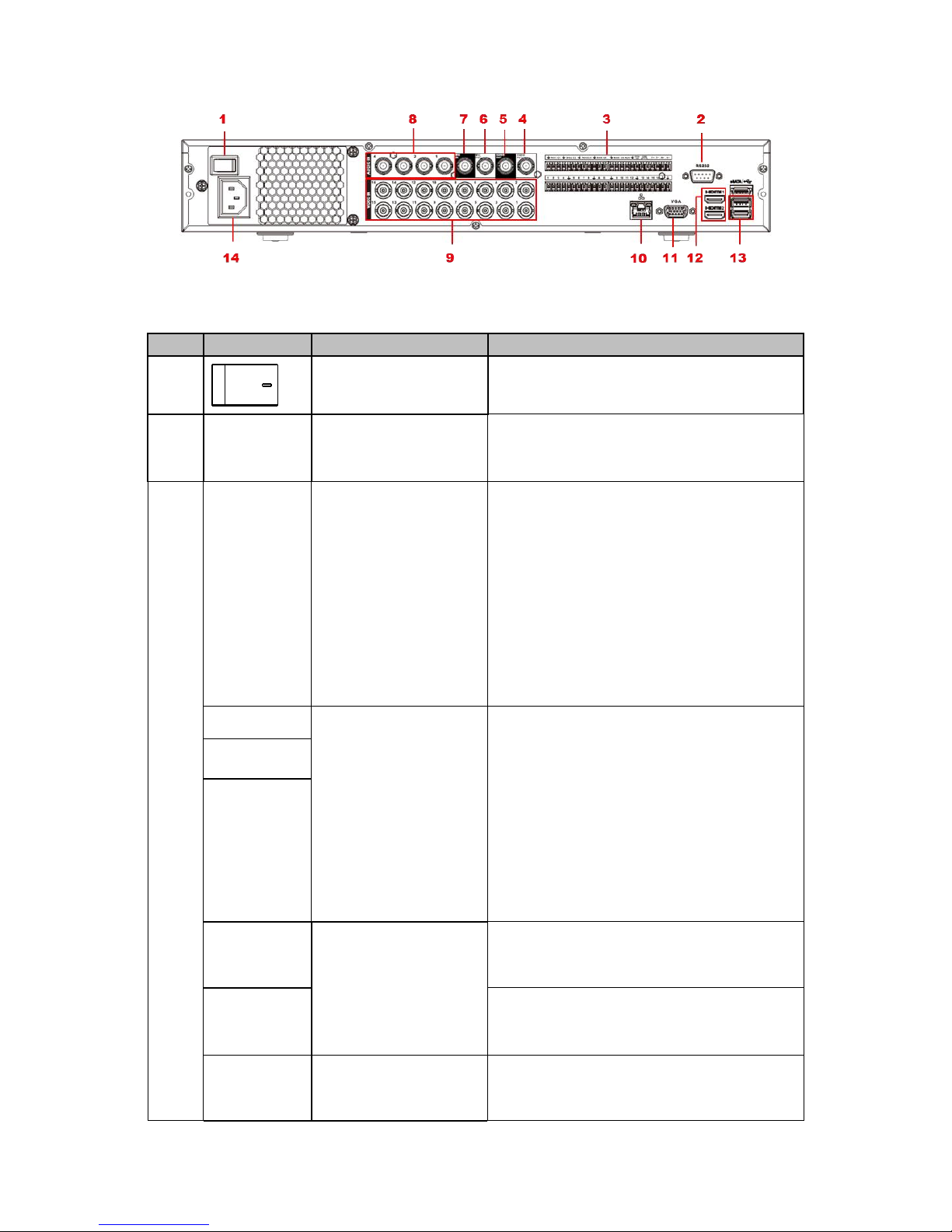
The rear panel of CJ-HDR416A is shown as below. See Figure 1-4.
Figure 1-4
Please refer to the following sheet for detailed information.
SN
Icon
Name
Note
1 Power switch
Power on/off button.
2
RS-232
RS-232 debug COM.
It is for general COM debug to configure IP
address or transfer transparent COM data.
3
1~16
Alarm input port 1~16
There are four groups. The first group is
from port 1 to port 4, the second group is
from port 5 to port 8, the third group is
from 9 to 12, and the fourth group is
from 13 to 16. They are to receive the
signal from the external alarm source.
There are two types; NO (normal
open)/NC (normal close).
When your alarm input device is using
external power, please make sure the
device and the DVR have the same
ground.
NO1~NO5
Alarm output port 1~5
5 groups of alarm output ports. (Group
1:port NO1~C1, Group 2: port NO2~
C2, Group 3: port NO3~C3, Group 4:
port NO4~C4, Group 5: port NO5, C5,
NC5). Output alarm signal to the alarm
device. Please make sure there is power
to the external alarm device.
NO: Normal open alarm output port.
C: Alarm output public end.
NC: Normal close alarm output port.
C1~C5
NC5
A
RS-485 communication
port
RS485_A port. It is the cable A. You can
connect to the control devices such as
speed dome PTZ.
B
RS485_B port. It is the cable B. You can
connect to the control devices such as
speed dome PTZ.
T+, T-, R+,
R-
Four-wire full-duplex
485 port
Four-wire full-duplex 485 port.
T+, T- : for the output wire.
R+, R- : for the input wire.

8
SN
Icon
Name
Note
CTRL 12V
Control power output
Controller 12V power output. It is to control
the on-off alarm relay output.
4
VIDEO OUT
Video output port
Connect to video output devices such as
TV.
5
AUDIO OUT
Audio output port
Audio output port. It is to output the analog
audio signal to the devices such as the
sound box.
6
MIC OUT
Audio output port
Audio output port. It is to output the analog
audio signal to the devices such as the
sound box.
Bidirectional talk output.
Audio output on 1-window video monitor.
Audio output on 1-window video
playback.
7
MIC IN
Audio input port
Bidirectional talk input port. It is to receive
the analog audio signal output from the
devices such as microphone, pickup.
8
AUDIO IN
Audio input port
It is to receive the analog audio signal
output from the devices such as
microphone, pickup.
9
VIDEO IN
Video input port
Connect to analog camera to input video
signal.
10 Network port
1000M Ethernet port.
11
VGA
VGA video output port
VGA video output port. Output analog video
signal. It can connect to the monitor to view
analog video.
12
HDMI
High Definition Media
Interface
High definition audio and video signal
output port. It transmits uncompressed high
definition video and multiple-channel data to
the HDMI port of the display device.
14 USB3.0 port
USB3.0 port. Connect to mouse, USB
storage device, USB burner and etc.
15 Power socket
Power socket.
9
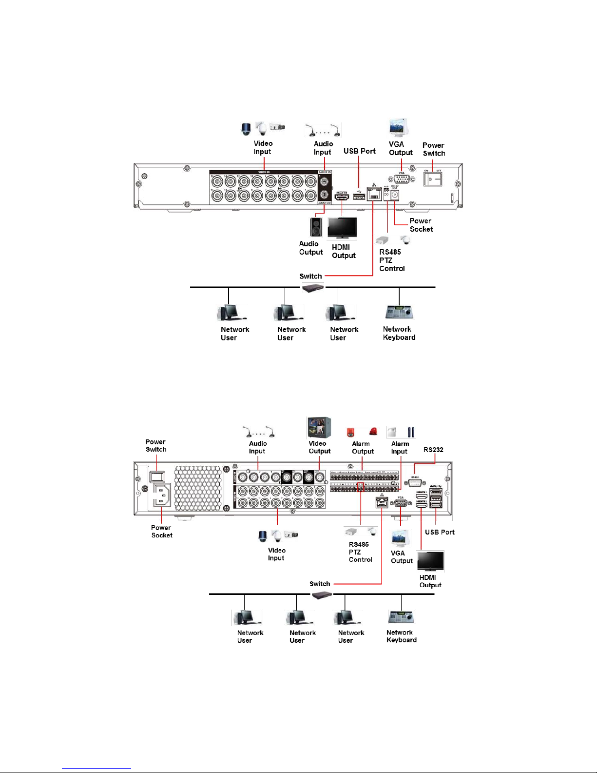
1.8 Connection Sample
CJ-HDR216A
The connection sample is shown as below. See Figure 1-5.
Figure 1-5
CJ-HDR416A
The connection sample is shown as below. See Figure 1-6.
Figure 1-6

10
1.9 Alarm Input and Output Connection
Important
Please refer to the specifications for the alarm input and output channel amount. Do not merely
count the alarm input and out channel amount according to the ports on the rear panel.
1.9.1 Alarm Input and Output Details
Figure 1-7
1,2,3,4,5,6,7,8,9,10,11,12,13,14,15,16
Alarm input port 1~16. The alarm becomes active
in low voltage.
NO1 C1,
NO2 C2,
NO3 C3,
NO4 C4,
NO5 C5 NC5
There are 5 groups of alarm output ports.
NO: Normal open alarm output port.
C: Alarm output public end.
NC: Normal close alarm output port.
CTRL 12V
Control power output. For external alarm, you
need to close the device power to cancel the
alarm.
Voltage current: 500mA.
12V
Rated current.
Voltage current: 500mA.
Earth cable.
A/B
RS485 communication port. They are used to
control devices such as decoder. 120Ω should be
parallel connected between A, B lines if there are
too many PTZ decoders.
T+, T-, R+, R-
They are four-wire full-duplex RS485 port
T+ T-: output wire
R+ R-: input wire
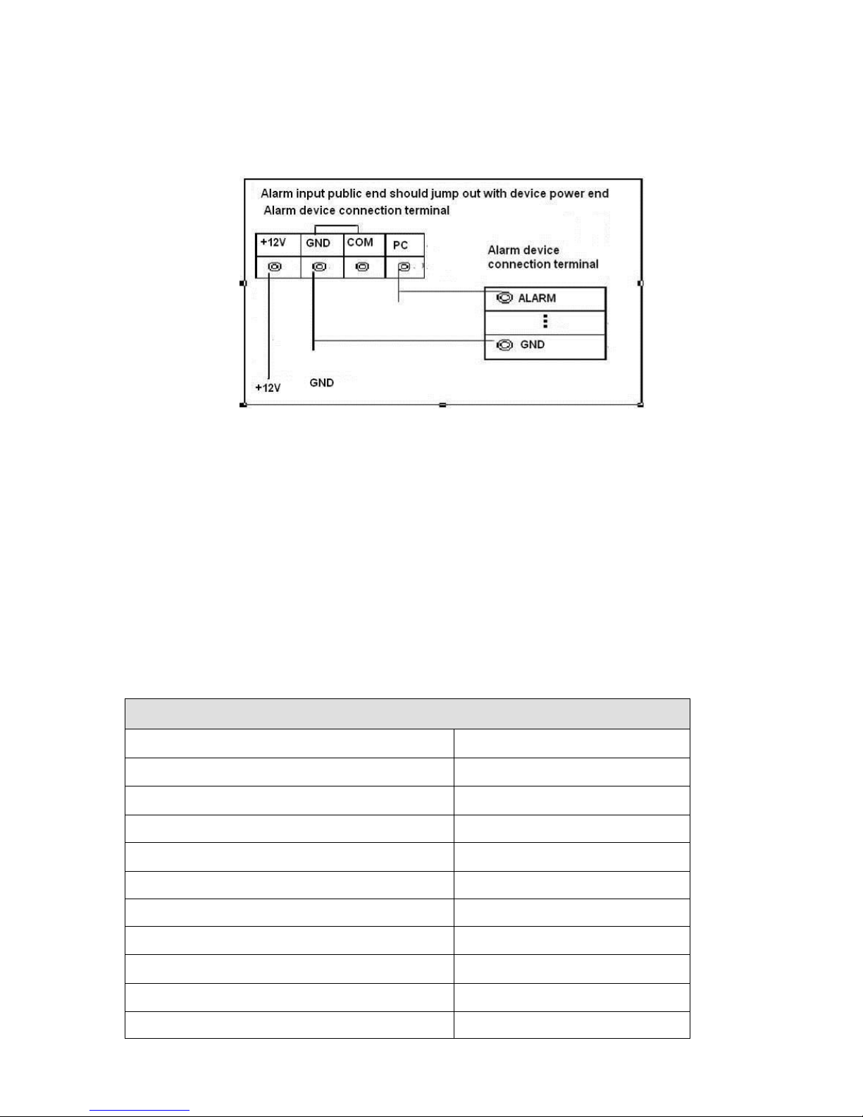
1.9.2 Alarm Input Port
Please refer to the following sheet for more information.
Grounding alarm inputs. (Normal open or Normal close type).
Please parallel connect COM end and GND end of the alarm detector (Provide external power
to the alarm detector).
11
Please parallel connect the Ground of the DVR and the ground of the alarm detector.
Please connect the NC port of the alarm sensor to the DVR alarm input (ALARM).
Use the same ground with that of DVR if you use external power to the alarm device.
Figure 1-8
1.9.3 Alarm Output Port
Provide external power to external alarm device.
To avoid overloading, please read the following relay parameters sheet carefully.
RS485 A/B cable is for the A/B cable of the PTZ decoder.
T+, T-, R+, R- are four-wire double duplex RS485 port.
T+ T-: output wire.
R+ R-: input wire.
Relay Specification
Model: HFD23-005-1ZS
Contact arrangement
1Z
Contact resistance
100mΩ (0.1A 6VDC)
Contact material
AgNi+
Contact rating (Res. Load)
0.5A 125VAC / 1A 30VDC
Max. switching voltage
125VAC / 60VDC
Max. switching current
2A
Max. switching power
62.5VA / 30W
Max. applicable load
1mA 5V
Mechanical endurance
1 x 107 times (300 times/min)
Electrical endurance
1 x 105 times (30 times/min)
Insulation resistance
1000MΩ (500VDC)

12
Dielectric strength
Between coil and contacts
1000VAC 1min
Between open contacts
400VAC 1min
Operate time (at nomi. volt.)
≤5ms
Release time (at nomi. volt.)
≤5ms
Bounce time (at nomi. volt.)
Approx. 5ms
Temperature rise (at nomi. volt.)
≤65K
Shock resistance
98m/s2
Vibration resistance
10Hz – 55Hz 3.3mm DA
Humidity
98%RH, 40°C
Ambient temperature
-30°C - 70°C
Unit weight
Approx. 2.2g
Termination
PCB (DIP)
Construction
Sealed plastic
 Loading...