

Panasonic CF-W4GWCZZBM Service Manual
ORDER NO. CPD0511051C1
Personal Computer
CF-W4
This is the Service Manual for
the following areas.
M …for U.S.A. and Canada
Model No. CF-W4GWCZZ 1 2
1
B: Microsoft
2
: Operation System
: Area
M: Refer to above area table
®
Windows® XP Professional
© 2005 Matsushita Electric Industrial Co., Ltd. All rights reserved.
Unauthorized copying and distribution is a violation of law.
LASER SAFETY INFORMATION
For U.S.A
Class 1 LASER-Product
This product is certified to comply with DHHS Rules 21 CFR Subchapter J.
This product complies with European Standard EN60825 (or IEC Publication 825)
For all areas
This equipment is classified as a class 1 level LASER product and there is no hazardous LASER radiation.
Caution:
(1) Use of controls or adjustments or performance of procedures other than those specified herein may result
in hazardous radiation exposure.
(2) The drive is designed to be incorporated into a computer-based system or unit which has an enclosing
cover. It should never be used as a stand alone drive.
Danger:
The serviceman should not remove the cover of drive unit and should not service because the drive unit is a
non-serviceable part.
Please check DANGER label on bottom cabinet of the equipment.
. Unplug the AC power cord and remove the battery pack from the equipment before opening the top cover of
the drive.
. When the power switch it on, do not place your eyes close to the top cover to look into the interior of the unit.
LASER Specification
Class 1 level LASER Product
Wave Length: DVD 650 660 nm
CD
778 787 nm
Laser safety information is appropriate only when drive with laser is installed.
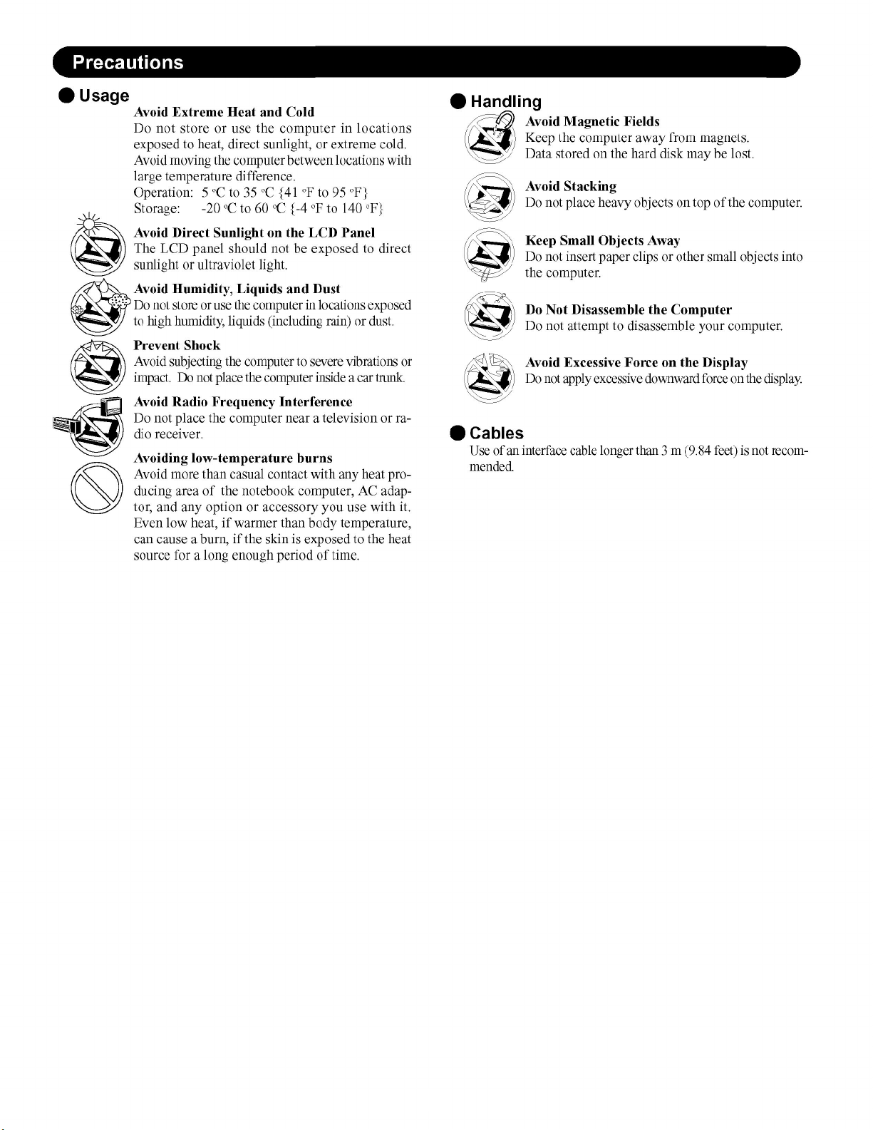
Handling
A
B
This computer has been designed so as to minimize shock to the LCD and hard disk drive, etc.,
but no warranty is provided against such trouble. Therefore, as a precision instrument, be
extremely careful in the handling.
Do not carry the computer while the display is open, or carry it by gripping the display or the
cabinet around the display (see figure A). When closing the display, ensure that the latch is
positioned correctly in the slot .
Do not carry your computer when the power is on.
Do not drop or hit your computer against solid objects.
Remove all external devices, cables, PC Cards sticking out of the computer (see figure B),
SD memory cards, and MultiMedia Cards before transporting the computer.
We recommend preparing a fully charged battery pack.
When transporting a spare battery pack inside a package, briefcase, etc., it is recommended
that it be placed in a plastic bag so that its contacts are protected.
Always carry your computer with you. Never check it in with luggage. For use of the computer inside an aircraft, we recommend asking the airlines regarding their policy on this issue.
It is a good idea to make backup copies on disks and carry them with you.
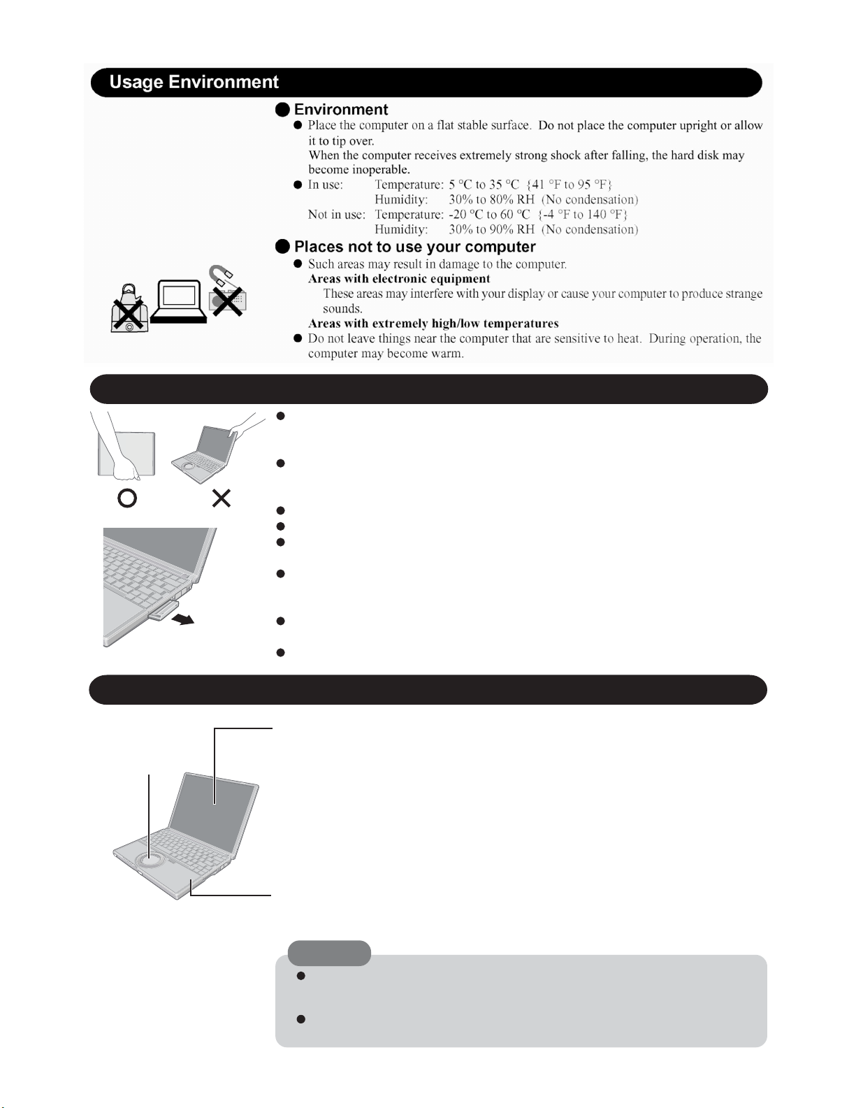
Maintenance
Touch Pad
Display
Avoid using water when cleaning the panel. Ingredients included in water may leave scratches
and reduce readability of the screen.
<When cleaning dust/dirt>
Avoid rubbing off dust/dirt with cloth since it may leave scratch on the screen.
Sweep dust/dirt with fine brush, then wipe it with a dry soft cloth used for cleaning glasses.
<When cleaning oily surface>
Apply camera lens cleaner on a soft gauze and clean it with gentle force. Then, wipe with a
dry soft cloth used for cleaning glasses.
Areas excluding the display
Wipe these areas with a soft cloth, after applying water or detergent diluted with water to the
soft cloth and firmly wringing out excess water.
CAUTION
Do not use benzene, thinner, or rubbing alcohol. Doing so may adversely affect the
surface, e.g., discoloration. In addition, do not use commercially-available household
cleaners and cosmetics, as they may contain components harmful to the surface.
Do not directly add or spray water or detergent. If liquid enters the inside of the
computer, it may cause it to work improperly or be damaged.
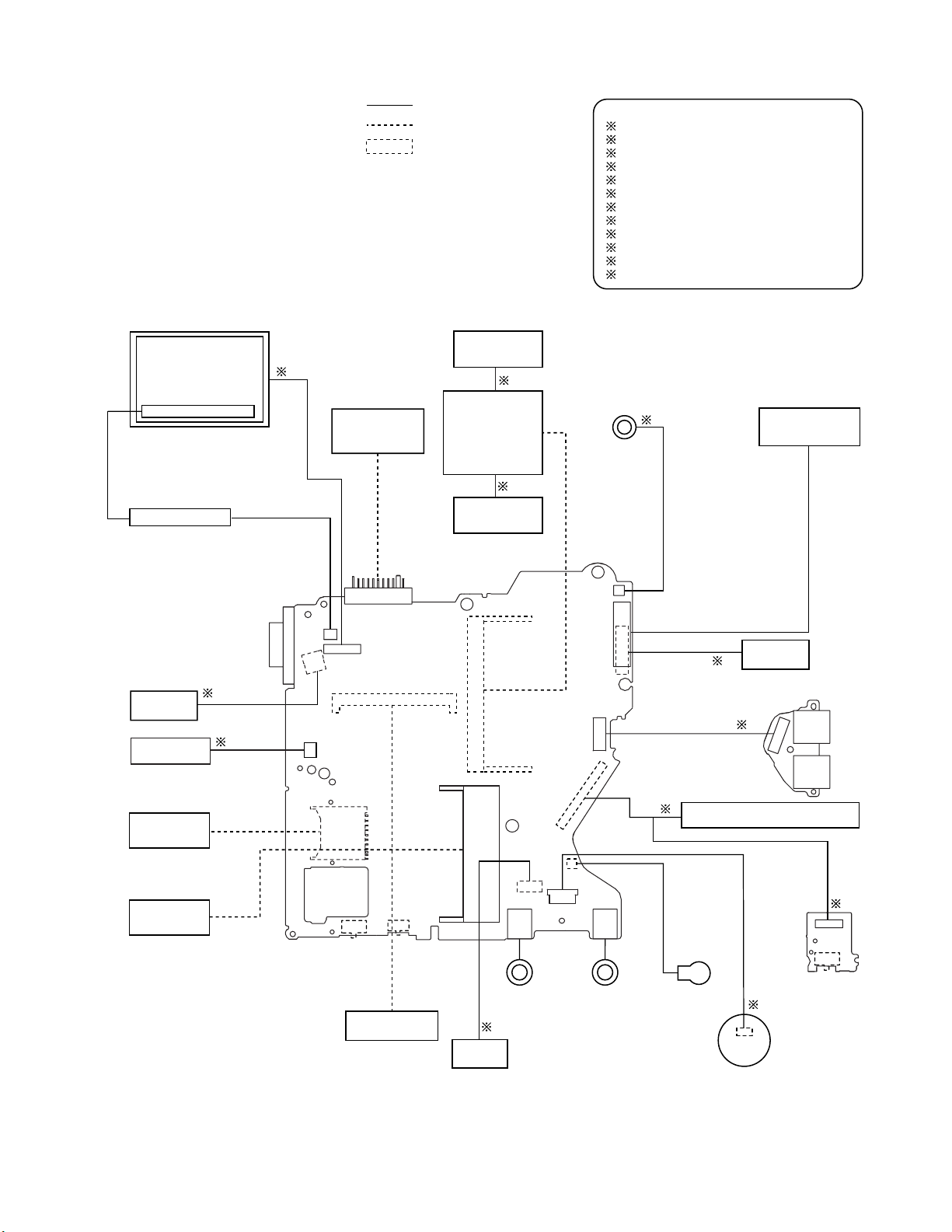
1 Connection Diagram
LCD
LCD Back Light
Inverter Board
Connection by Cable
Direct connection Connectors
Parts on Bottom Side
Antenna Board
(R)
2
Battery Pack
LAN Module
Antenna Board
6
Wireless
5
(L)
Connection Cable
1 Drive FFC DFJK9000ZA
2 LCD Cable DFJS957ZA
3 Speaker Cable DFJS962ZA
4 SW Board FFC DFJE20T108BB
5 Antenna PCB-L N1ZYYY000002
6 Antenna PCB-R N1ZYYY000001
7 Modem Cable DFJS959ZB
8 LAN Cable DFJS979ZA
9 PAD FFC DFJE12U112BB
10 HDD FPC Unit DL3UP1443AAA
11 DC-IN Cable DFJS961ZB
12 Main-Sub Cable DFJS960ZA
3
Speaker
Keyboard
DC-IN
MODEM
SD Card
PCMCIA
SLOT
CN601
CN26
CN12
CN10
CN600
CN18
POWER SW
CN11
CN13
SW6
DIMM memory
CF-BAV0256U
CF-BAV0512U
Main Board
CN2
SW 7
W-LAN ON/OFF
(Option)
CN19
CN14
CN16
JK2
Headphone
8
LAN
VGA
11
7
CN23
CN25
CN3
CN15
CN4
CN21
JK1
Mic
USB Board
1
CD-RW,DVD-ROM Drive
Lithium Battery
Touch Pad
10
CN901
HDD
12
SW Board
9
CN902
CN903
CN951
SW951
Open SW
USB
USB
4
1-1
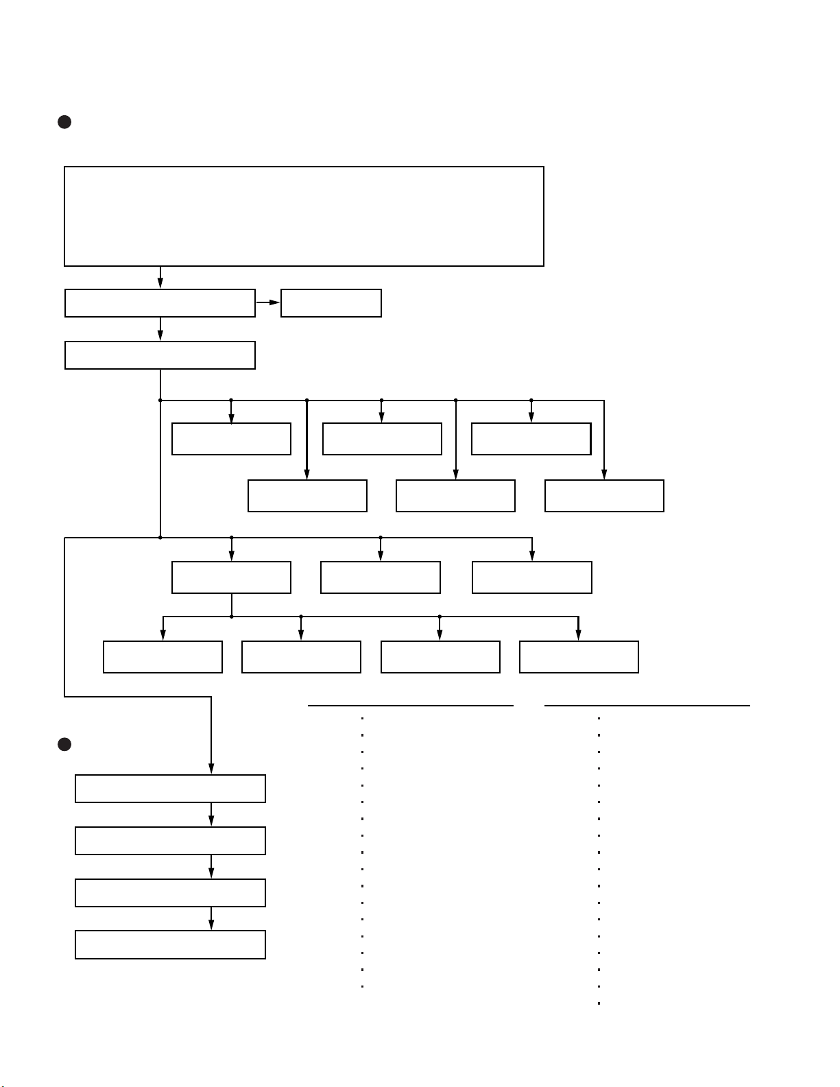
2 Disassembly instructions
2.1. Disassembly Flow Chart
Main Unit
9.2.1.
Preparation
1. End the Windows.
2. Turn off the Power, and then remove the AC Adaptor or Battery Pack.
3. Remove any optional DIMM Memory Cards or PCMCIA Cards.
4. Remove any other peripherals or Connected Devices.
9.2.2.
Keyboard
9.2.4.
Top Case
9.2.5.
9.2.11.
9.2.14. 9.2.15.
Antenna Board
(L, R) / DC-IN
9.2.3.
HDD
9.2.7. 9.2.9.
SW Board
9.2.6. 9.2.8.
Disk Cover
Main Board USB Board
W-LAN Module MODEM Card Bus ejector
Touch Pad
LCD Knob
9.2.12. 9.2.13.
Drive Unit
9.2.16. 9.2.17.
Speaker
9.2.10.
Solenoid
Display Unit
9.2.18.
LCD Unit
9.2.19.
Hinge Cover
9.2.20.
LCD Unit / LCD Rear
9.2.21.
Inverter Board
Main replaceable parts
9.2.1.
Battery Pack
DIMM Cover
Side Cover
9.2.2.
9.2.3.
Keyboard
HDD
HDD FFC
HDD Cover
9.2.4.
9.2.5.
Top Case
SW Board
Disk Cover Open Knob
9.2.6.
9.2.7.
Disk Cover
Touch Pad
Touch Pad Knob
Touch Pad Ring
PAD FFC
9.2.8.
9.2.9.
LCD Knob
Speaker
2-1
9.2.10.
9.2.11.
9.2.12.
9.2.13.
9.2.14.
9.2.15.
9.2.16.
9.2.17.
9.2.18.
9.2.19.
9.2.20.
9.2.21.
Solenoid
Main Board
Drive Unit
USB Board
Antenna Board
Antenna Cover(L, R)
W - LAN Module
Heat Spreader
MODEM
Card Bus ejector
LCD Unit
Hinge Cover
Hinge (L, R)
LCD Unit
LCD Rear
LCD Front
Inverter Board
LCD Cable
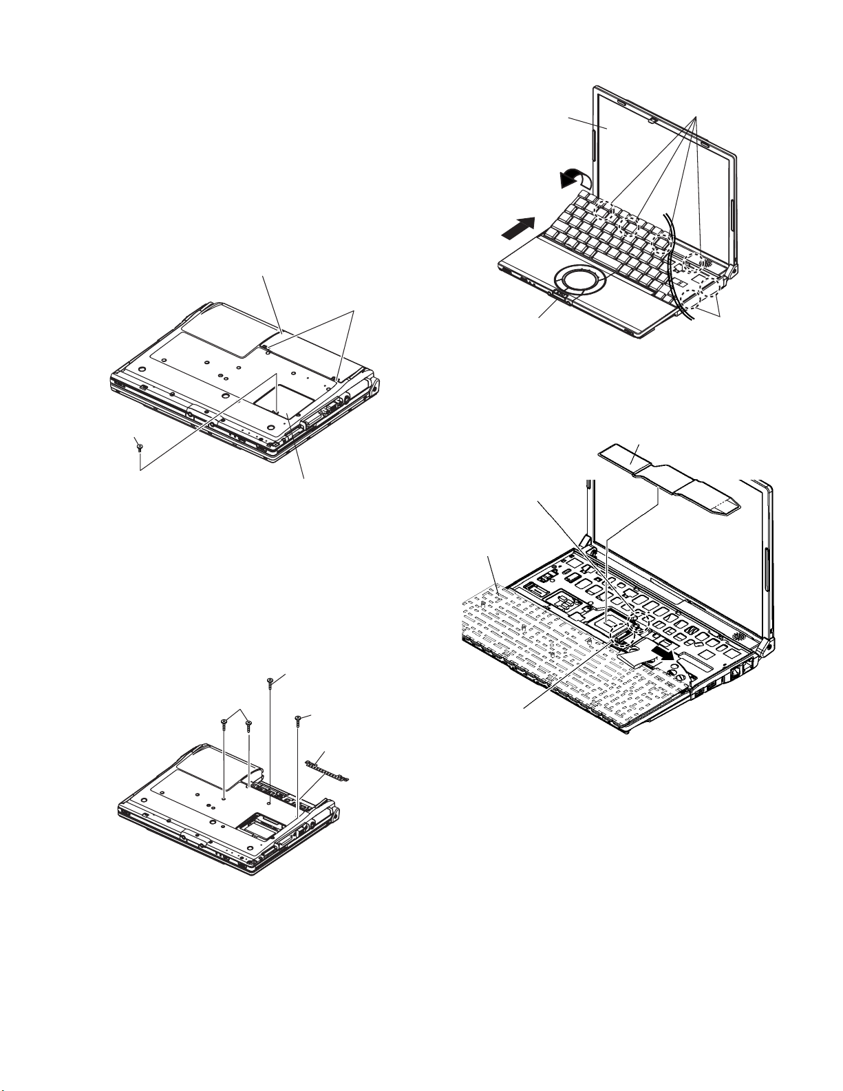
2.2. Disassembly
2.2.1. Preparation
5. Open the Keyboard from LCD side and then turn it inside
out on the Top Case.
Attention:
Before disassembly, be sure to perform the following steps.
1. End the Windows.
2. Turn off the power and then remove the AC Adaptor.
3. Slide the Hooks (A) and then remove the Battery Pack.
4. Remove the Screw (A) and then remove the DIMM cover.
(Remove if the DIMM memory is equipped with)
Screw(A):XSB2+4FNL(N16)
Battery Pack
Hook (A)
Screw (A)
DIMM cover
LCD unit
LCD Knob
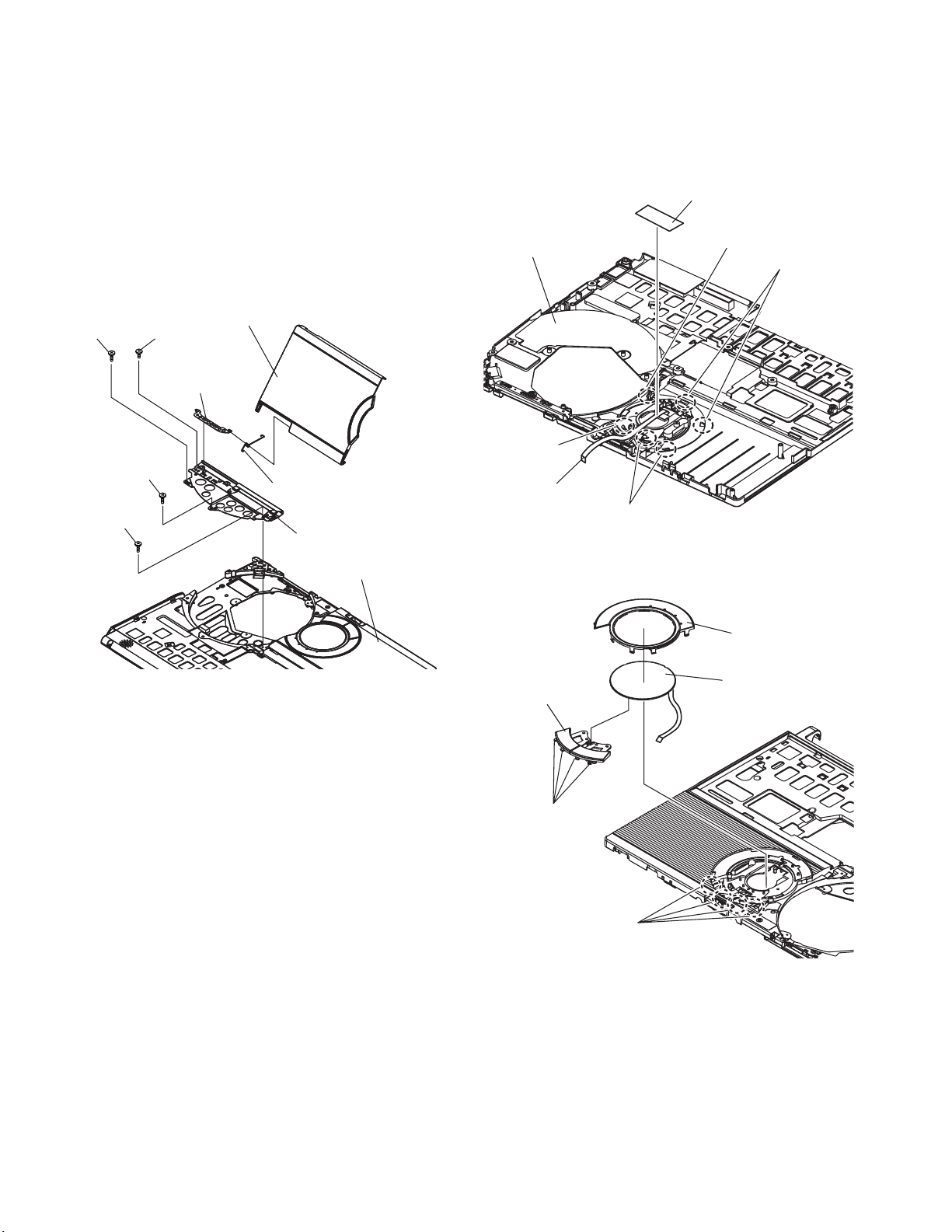
6. Remove the Heat Spreader from buttom of the Keyboard.
7. Remove the Keyboard FFC from the Connector (CN15),
(CN26) and then remove the Keyboard.
Heat Spreader
CN26
Hook (B)
Hook (B)
2.2.2. Remove the Keyboard
Preparation : perform the section 2.2.1. first.
1. Remove the 4 Screws (F).
Screw(F):DXQT2+E12FNL(N11)
2. Remove the Keyboard Hook Plate and then remove the
Hook of back side of Keyboard with small screwdriver.
Screw (F)
Screw (F)
Screw (F)
Keyboard Hook Plate
3. The LCD unit is opened up to about 90° by operating the
LCD Knob.
4. Remove the 6 Hooks (B).
Keyboard
CN15
2-2

2.2.3. Remove the HDD
2.2.4. Remove the Top Case
Preparation : perform the section 2.2.1. 2.2.2. first.
1. Remove the 2 Screws (V).
Screw(V):DFHE5025XA(N1)
2. The slide is done in the direction of the arrow and the HDD
Cover is removed.
Screw (V)
HDD Cover
3. Lift up the HDD Unit and remove the FFC Connector and
then remove the HDD Unit.
4. HDD is taken out of the HDD Case.
Note:
Please do not bend pins of the HDD Connector, at the
time of removing HDD and FFC Connector.
Preparation : perform the section 2.2.1. , 2.2.2. first.
1. Insert a small screwdriver into the hole and slide the look in
the direction shown by arrow (C) to open the Disc Cover.
2. The Anttena Cover (R) is rotated from the Bottom Case side
in the direction of arrow (A) and the Antenna Cover (R)
removed in the direction of arrow (B).
LCD unit
Antenna cover (R)
B
A
C
Back Side
HDD Unit
HDD Case
HDD
FFC Connector
HDD FFC
Small
Hole
screwdriver
3. Remove the 3 Screws (B), 2 Screws (C) and 3 Screws (E)
from the Bottom Case.
Screw(B):DRHM0092ZA(N4)
Screw(C):DXHM0057ZA(N7)
Screw(E):DXHM0039ZA(N6)
Screw (B)
Screw (B)
Screw (E)
Screw (B)
Screw (E)
Screw (E)
2-3
Screw (C)
Screw (C)
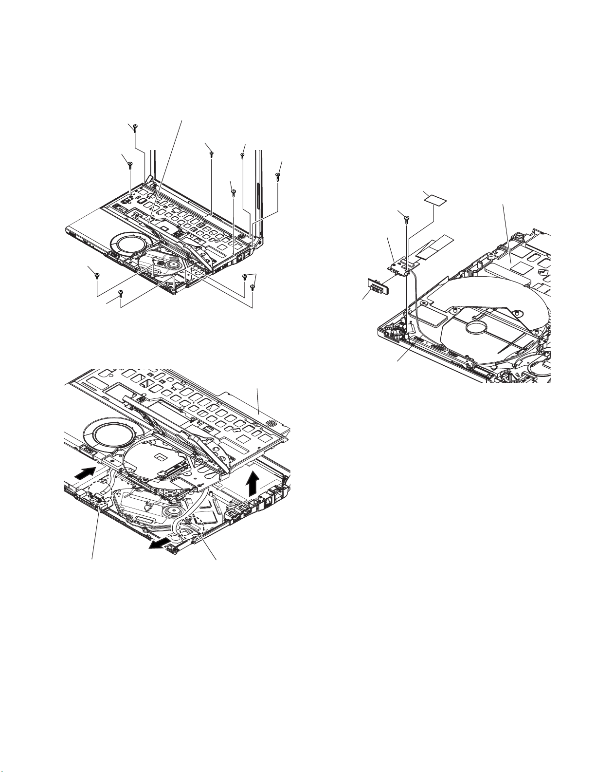
4. Remove the 3 Screws (I), 2 Screws (J), 2 Screws (K) and 2
Screws (L) from the Top Case.
Screw(I):DXQT2+E6FNL(N13)
Screw(J):DXQT26+D8FCL(N16)
Screw(K):DXQT2+E6FCL(N12)
Screw(L):DFHE5025XA(N1)
Screw (J)
Screw (I)
Screw (L)
Disc Cover
Screw (K)
Screw (K)
Screw
(J)
Screw
(I)
Screw (L)
2.2.5. Remove the SW Board
Preparation : perform the section 2.2.1. to 2.2.3. first.
1. Peel off the Tape.
2. Remove the Solenoid Cable.
3. Remove the 1 Screw (Q) and then remove the SW Board.
Screw(Q):DXHM0057ZA
Note:
Note it that the Disc Eject Knob comes off at the same
time.
Tape
Screw (Q)
Switch Board
Top Case
Screw (I)
5. Lift up the Top Case, remove the Pad FFC and then
remove the Top Case.
Top Case
FFC (PAD)
FFC (SW)
Disc Eject Knob
Solenoid Cable
2-4
2.2.6. Remove the Disc Cover
2.2.7. Remove the Touch Pad
Preparation : perform the section 2.2.1. to 2.2.3. first.
1. Remove the 2 Screw (R), 1 Screw (S) and 1 Screw (T) of
the Disk Angle.
Screw(R):DXQT2+E12FNL(N11)
Screw(S):DXQT2+E6FNL(N13)
Screw(T):DXHM0057(N7)
2. Slide the Disc Cover to the Disc Cover Shaft and remove
the Cover.
3. The Disk Cover Shaft is pulled out while sliding and
removed it from the Disk Angle in the direction of the Touch
Pad.
Screw (R)
Screw (T)
Screw (S)
Disk Cover Shaft
Screw (R)
Disc Cover
Disc Cover Spring
Disk Angle
Top Case
Preparation : perform the section 2.2.1. to 2.2.3. first.
1. Peel off the Tape.
2. The 6 Hooks of the Pad Cover are depressed in the
direction of the center of the Touch Pad by using the small
screwdriver.
Tape
Top Case
Hook
PAD FFC
Hook
Hook
Hook
3. Remove the Hooks of the Toutch Pad and the Pad Button,
and remove the Touch Pad.
Pad bottun
Hook (F)
Pad Cover
Touch Pad
Hook (F)
2-5
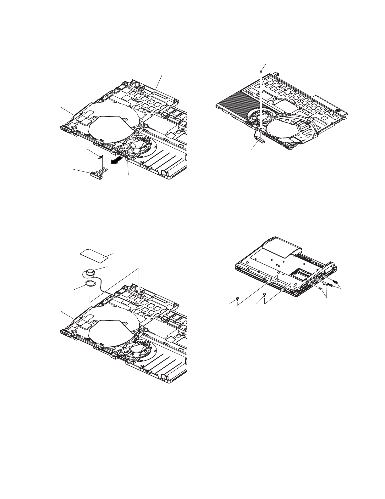
2.2.8. Remove the LCD Knob
2.2.10. Remove the Solenoid
Preparation : perform the section 2.2.1. to 2.2.3. first.
1. Remove the Spring from the Top Case.
2. Remove the Hook of LCD Knob from the Stopper Rib of the
Top Case and then the LCD Knob is removed.
Stopper Rib
Top Case
Latch
Spring
LCD Knob
Location of the Spring
2.2.9. Remove the Speaker
Preparation : perform the section 2.2.1. to 2.2.3. first.
1. Peel off the Speaker Box Sheet.
2. Peel off the tape on the Speaker and Speaker Ring and
then remove the Speaker.
Preparation : perform the section 2.2.1. to 2.2.3. first.
1. Remove the 1 Screw (Z) and then remove the Solenoid.
Screw(Z):DXQT2+F2FNL(N14)
Screw
Solenoid
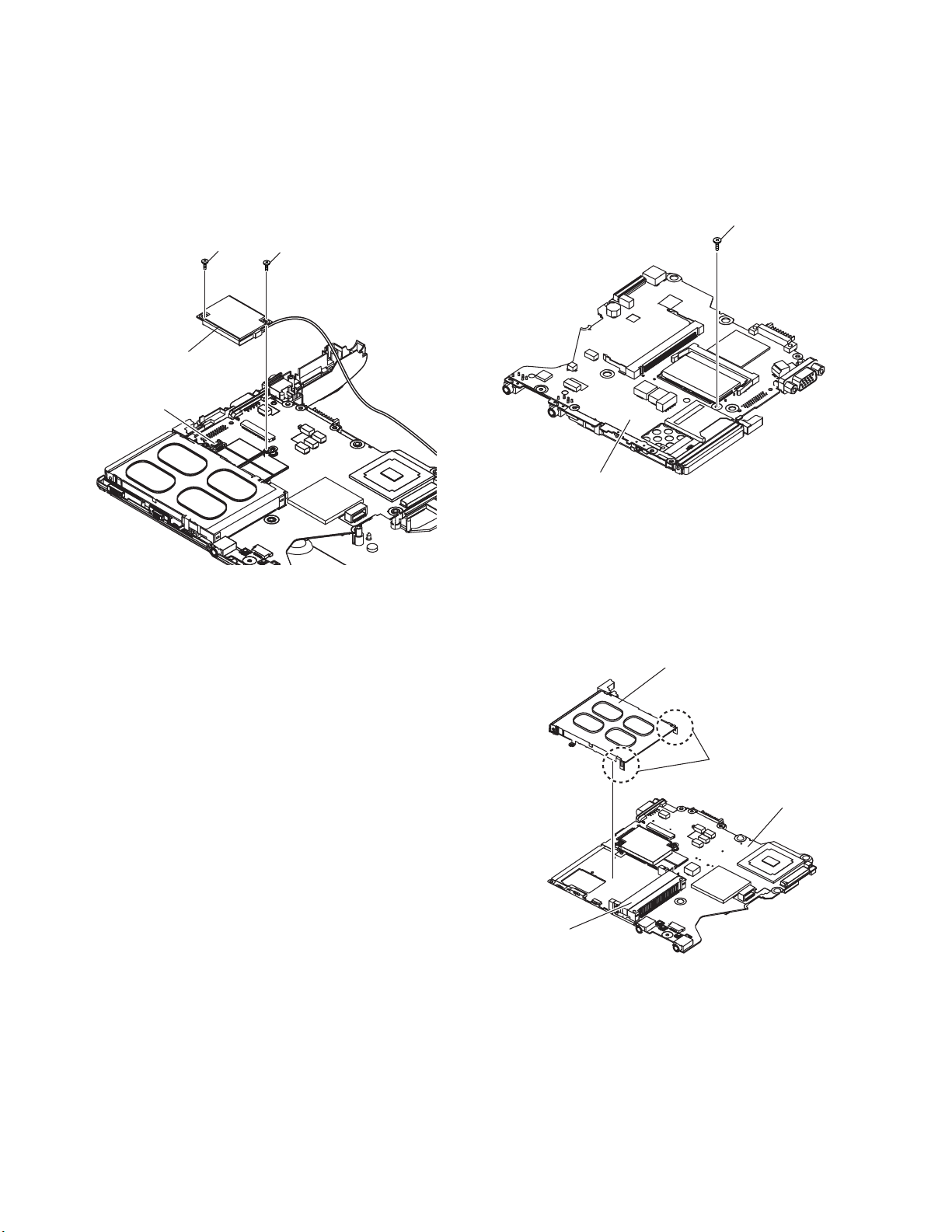
2.2.11. Remove the Main Board
Preparation : perform the section 2.2.1. to 2.2.3. first.
1. Remove the 1 Screw (D), (H) and 2 screws.
Screw(D):DXQT2+E10FNL(N10)
Screw(H):DXQT2+D4FNL(N9)
Screw(G):DFHE5035ZB(N2)
Screw(W):K1YE50000022(N500)
Speaker
Ring
Top Case
Speaker Box Sheet
Speaker
Screw (D)
2. Remove the 2 Screws (N).
Screw(N):DXQT2+E6FNL(N13)
3. Remove the Connector (CN23)
Screw (H)
Screw (G)
Screw (W)
2-6
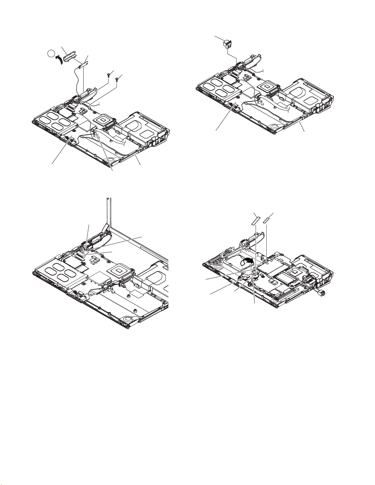
4. The Antenna Cover (L) is inclined in the direction of arrow
A and remove it.
Remove the Antenna Cover (L) from the Top Case.
Antenna Cover (L)
6. Remove the DC-IN Jack Holder.
DC Jack
Holder
A
Main Board
Antenna PCB (L)
Screw (N)
Screw (N)
Bottom Case
CN23
5. Remove the Connectors (CN10) and (CN11) of LCD Cable.
LCD Cable
Main Board
Bottom Case
7. Returns the Main Board on the reverse.
Peel the Tape of the Drive FFC and remove the FFC.
8. Remove the Connector (CN3) and the Connector (CN16) of
LAN Cable.
Peel off the Tape of HDD FFC and remove the FFC.
Remove the Main Board.
Tape
Tape
CN11
CN10
LAN
cable
Lithium Battery
Cable
CN3
CN16
2-7
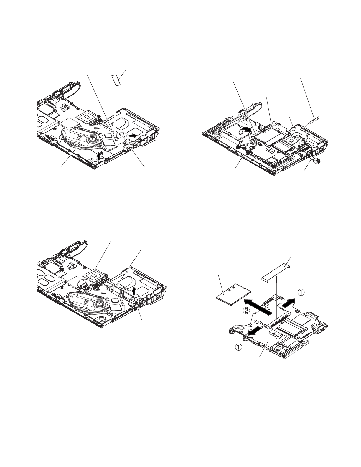
2.2.12. Remove the Drive Unit
2.2.14. Remove the Antenna Board(L,R)
Preparation : perform the section 2.2.1. to 2.2.3. first.
1. Peel off the Tape from the Connector.
2. Remove the Drive FFC from the Connector (CN501) and
remove out the Drive Unit.
CN501
Drive unit
Tape
Drive FFC
2.2.13. Remove the USB Board
Preparation : perform the section 2.2.1. to 2.2.3. first.
1. Remove the Connector (CN23) on the Main Board.
2. Remove the USB Board from the Bottom Case.
CN23
USB Cable
Preparation : perform the section 2.2.1. to 2.2.10. first.
1. Remove the Antenna Cable (L, R) on the Wireless LAN
Module and then remove the Antenna Board from the
Bottom Case.
2. Remove the DC-IN Cable (CN600) from the Main Board.
Antenna Cable (R)
Antenna Cable (L)
Bottom Case
Antenna PCB (L)
CN600
DC - IN Cable
2.2.15. Remove the Wireless LAN Module
Preparation : perform the section 2.2.1. to 2.2.3. and 2.2.10.
first.
1. Peel off the Tape on the Wireless LAN Module.
2. Open the Wireless LAN Module maintenance arm and
remove the Wireless LAN Module.
Tape
USB Board
Wireless LAN
Module
Main Board
2-8
2.2.16. Remove the MODEM
2.2.17. Remove the Card Bus Ejector
Preparation : perform the section 2.2.1. to 2.2.3. and 2.2.10.
first.
1. Remove the 2 Screws (O).
Screw(O):DXQT2+D25FNL(N8)
2. Remove the MODEM to the vertical direction from
Connector (CN8) on the Main Board.
Screw (O)
MODEM
CN18
Screw (O)
Preparation : perform the section 2.2.1. to 2.2.3. and 2.2.10.
first.
1. Remove the 1 Screw (P) from connected side of Main
Board.
Screw(P):DFHE5025XA(N1)
Screw (P)
Main Board
2. Return it on the revers to Card Bus Ejector side.
3. Remove the 2 hooks (C) of the Card Bus Ejector from the
Connector (CN14) and the Card Bus Ejector is removed.
Card Bus Ejector
Hook(C)
Main Board
CN14
2-9
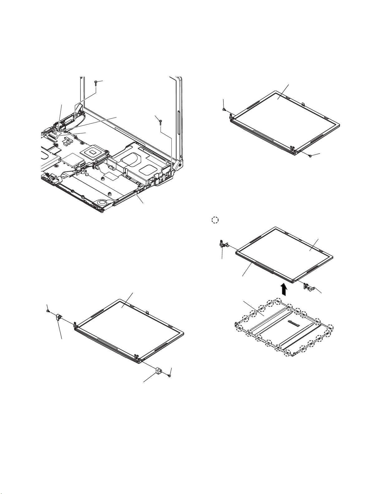
2.2.18. Remove the LCD Unit
Preparation : perform the section 2.2.1. to 2.2.3. first.
1. Remove the 2 Screws (M)
Screw(M):DXQT26+D5FNL(N15)
2. Remove the LCD Cable from the Connectors (CN10) and
(CN11) on the Main Board and then remove the LCD Unit.
2.2.20. Remove the LCD Unit and the LCD
Rear
Preparation : perform the section 2.2.1. to 2.2.3. and 2.2.18.
to 2.2.19. first.
1. Remove the 2 Screws (Y).
Screw(Y):DRHM0074ZA(N3)
Screw (M)
LCD Cable
Screw (M)
CN10
CN11
Bottom Case
2.2.19. Remove the Hinge Cover
Preparation : perform the section 2.2.1. to 2.2.3. and 2.2.18.
first.
1. Remove the 2 Screws(U) and the Hinge Cover(L,R).
Screw(U):DRHM0074ZA(N3)
LCD Unit
Screw (U)
LCD Unit
Screw (Y)
Screw (Y)
2. The LCD Front Case and the combination parts of LCD
Rear Case are separated.
(Combination parts are 6 the top and bottom places for
each, 4 right and left places for each)
3. Remove the Hinge (L, R).
Hook Position
LCD Unit
Hinge (L)
LCD Front Case
LCD Rear Case
Hinge (R)
Hinge Cover (L)
Screw (U)
Hinge Cover (R)
2-10
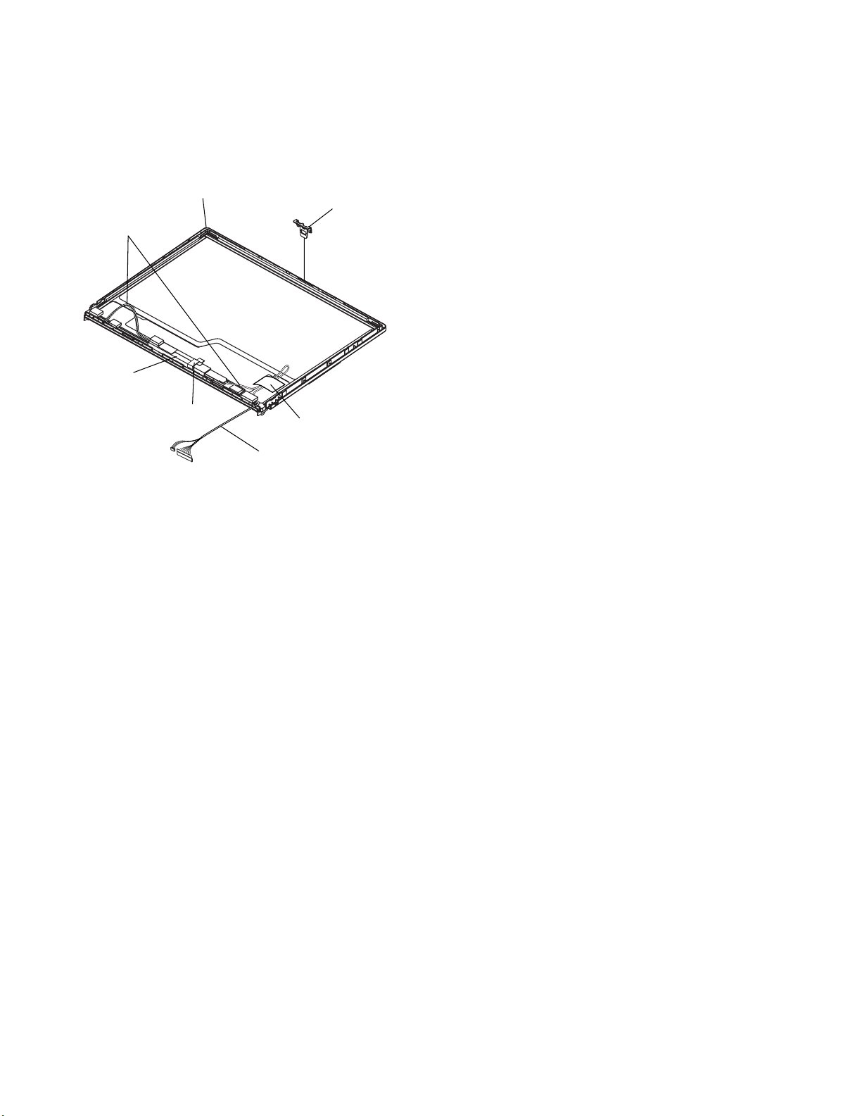
2.2.21. Remove the Inverter Board
Preparation : perform the section 2.2.1. to 2.2.4. and 2.2.17.
to 2.2.19. first.
1. Remove the LCD Cable from the Inverter.
2. Peel off the Tape for fixation from Inverter Case.
3. Remove the Inverter with the Inverter Case.
LCD Front Case
LCD High voltage
2pin Wire Rod
Inverter Box
LCD Hook
Tape
Gasket Cloth
LCD Cable
2-11
3 Reassembly instructions
3.1. Attention when CF-W4G series is repaired
· Please execute writing BIOS ID when you exchange the Main Board.
· Parts (Sheet and rubber) etc. related various the Conductive Cloth and Heat Spreader cannot be recycled. Use new parts.
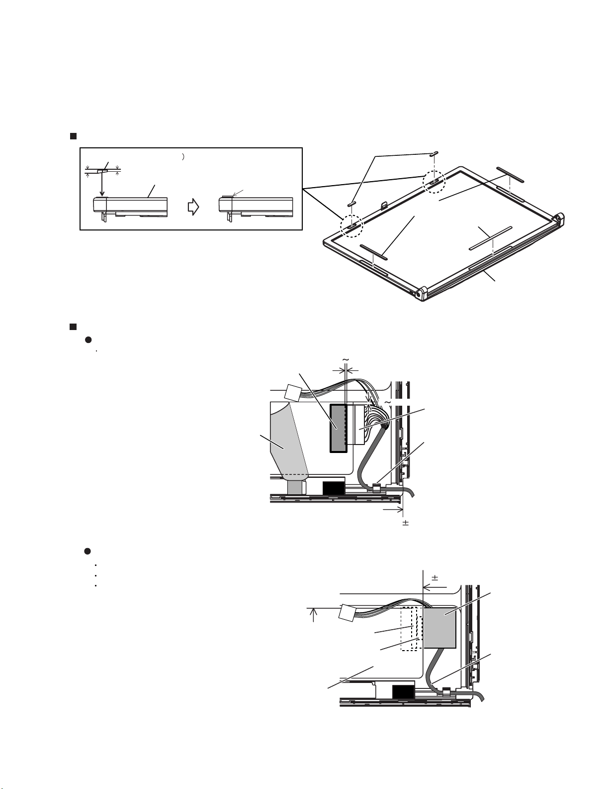
3.2. Assembly knowhow of part LCD
LCD Rubber, LCD side Rubber and LCD backing Rubber’s putting
LCD Rubber (Upper
LCD Rubber (Upper)
big small
LCD Front Case
LCD parallel after putting
LCD Cable processing
Clamping processing of LCD Cable, LCD Connector connection and putting of PET Tape of cable
The LCD Insulation Sheet is peeled off and after processes as shown in the figure below,
Put the Insulation Sheet.
PET Tape
LCD Insulation Sheet
1 2mm
2mm
1
LCD Side Rubber
LCD Back Rubber (Lower)
LCD Front Case
Connector
LCD Frame Clamp
A red line of the cable is matched to the LCD Frame externals.
Putting of The Conductive Cloth
The Conductive Cloth is put and after putting, a both side tape is put.
Process the part in the signal line of the LCD Cable in the Conductive Cloth.
Put the Conductive Cloth on the connector surely.
There must not be beginning to see from externals.
Connector of externals match
LCD Insulation Seat
Connector
Both Side Tape
3-1
0 1mm
Insulation seat of edge match
0 1mm
Conductive Cloth
(LCD Label)
LCD Cable
 Loading...