

Page 1
®
Port Replicator
for CF-51 Series
Personal Computers
CF-VEB511
ENGLISH
DEUTSCH
FRANÇAIS
OPERATING INSTRUCTIONS
Names and Functions of Parts ............................. 5
E
Connecting/Disconnecting ................................... 6
BEDIENUNGSANLEITUNG
Namen und Funktionen der Komponenten ......... 9
D
Anschließen/Entfernen ....................................... 10
MODE D’EMPLOI
Nom et fonction des pièces ................................ 13
Connexion/Déconnexion..................................... 14
F
Page 2

Interface Cable
Use of an interface cable longer than 3 m (9.84 feet) is not recommended.
Schnittstellenkabel
Verwendete Schnittstellenkabel sollten eine Länge von 3 Metern möglichst nicht überschreiten.
Cable d’interface
Nous vous déconseillons d’utiliser un câble d’interface d’une longueur supérieure à 3 m.
For U.S.A.
Federal Communications Commission Radio Frequency Interference Statement
Note: This equipment has been tested and found to comply with the limits for a Class B
digital device, pursuant to Part 15 of the FCC Rules. These limits are designed to provide
reasonable protection against harmful interference in a residential installation. This equipment generates, uses and can radiate radio frequency energy and, if not installed and used in
accordance with the instructions, may cause harmful interference to radio communications.
However, there is no guarantee that interference will not occur in a particular installation. If
this equipment does cause harmful interference to radio or television reception, which can
be determined by turning the equipment off and on, the user is encouraged to try to correct
the interference by one or more of the following measures:
Reorient or relocate the receiving antenna.
Increase the separation between the equipment and receiver.
Connect the equipment into an outlet on a circuit different from that to which the receiver
is connected.
Consult the Panasonic Service Center or an experienced radio/TV technician for help.
Warning
To assure continued compliance, use only shielded interface cables when connecting to a
computer or peripheral. Also, any changes or modifications not expressly approved by the
party responsible for compliance could void the user's authority to operate this equipment.
This device is Class B verified to comply with Part 15 of FCC Rules when used with
Panasonic Notebook Computer.
This device complies with Part 15 of the FCC Rules. Operation is subject to the following
two conditions:
(1) This device may not cause harmful interference, and
(2) This device must accept any interference received, including interference that may cause
undesired operation.
Responsible Party: Matsushita Electric Corporation of America
One Panasonic Way
Secaucus, NJ 07094
Tel No:1-800-LAPTOP-5 (1-800-527-8675)
For Canada
This Class B digital apparatus complies with Canadian ICES-003.
Cet appareil numérique de la classe B est conforme à la norme NMB-003 du Canada.
2
Page 3

-------------------------------------------------------------------------------------------------------------
Compliance Notice - CE Mark
This equipment is in conformance with the requirements of the European Council Directive
listed below:
73/23/EEC Low Voltage Directive with amendment 93/68/EEC
89/336/EEC EMC Directive with amendments 92/31/EEC and 93/68/EEC
This Notice is based upon compliance of the product to the following standards:
EN60950
EN55022
EN61000-3-2
EN61000-3-3
EN55024
-------------------------------------------------------------------------------------------------------------
Übereinstimmungserklärung - CE-Marke
Diese Ausrüstung erfüllt die Anforderungen der unten angegebenen EC-Direktive:
73/23/EEC Niederspannungsdirektive mit Abänderung 93/68/EEC
89/336/EEC EMC-Direktive mit Abänderungen 92/31/EEC und 93/68/EEC
Diese Erklärung beruht darauf, dass das Produkt die folgenden Normen erfüllt:
EN60950
EN55022
EN61000-3-2
EN61000-3-3
EN55024
-------------------------------------------------------------------------------------------------------------
Avis de conformité - Marque CE
Cet équipement est conforme aux conditions des Directives de la Commission Européenne
mentionnées ci-dessous:
73/23/EEC Directive sur la basse tension y compris la modification 93/68/EEC
89/336/EEC Directive CEM y compris les modifications 92/31/EEC et 93/68/EEC
Cet Avis se base sur la conformité du produit aux normes suivantes:
EN60950
EN55022
EN61000-3-2
EN61000-3-3
EN55024
3
Page 4
ENGLISH
Thank you for purchasing the port replicator for the Panasonic CF-51 notebook computer series*.
By connecting your peripheral devices to the port replicator, you can save
yourself the trouble of having to connect and disconnect several cables every
time you transport the computer.
E
* This port replicator cannot be used for other models.
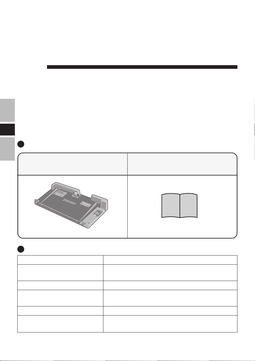
Parts Inclusion
Port Replicator ......................... 1
(with expansion bus connector protective cap)
Operating Instructions ............ 1
Specifications
Item
Power Supply Input
Expansion Bus Connector
Physical Dimensions
(Width × Height × Depth)
Weight
Operating Environment
Temperature / Humidity
Refer to “Specifications” in the “OPERATING INSTRUCTIONS” accompanying the computer for information
on the connectors and ports on the rear panel of the port replicator.
4
DC 15.6 V [Do not use other than the specified AC
adaptor (Model No. CF-AA1653A)].
100-pin
378 mm × 64 mm × 219 mm
{14.9" × 2.6" × 8.7"}
Approx. 1.3 kg {2.9 lb.}
5 to 35 °C {41 to 95 °F} / 30 to 80 % RH
(No condensation)
Description
Page 5
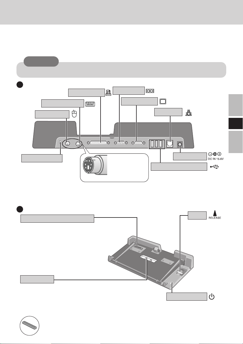
Names and Functions of Parts
The port replicator allows your peripheral devices to function exactly as if they were connected directly to the computer. (Refer to “Names and Functions of Parts” in the “OPERATING INSTRUCTIONS” accompanying the computer.)
CAUTION
Do not touch the expansion bus connector, pins or springs of the port replicator.
Rear
Parallel Port
Keyboard Port
Mouse Port
Security Lock
A Kensington cable can
be connected. For more
information, read the
manual that comes with
the cable.
LOCK
Serial Port
Display Port
Check whether
the connectors
are pointing up or
down.
Front/Right Side
Expansion Bus Connector
This connects to the expansion bus
connector on the bottom of the computer.
Be sure to keep it covered with the supplied protective cap when the port
replicator is not connected to the computer.
Cap Holder
The protective cap from the expansion bus connector
should be placed here when the port replicator is connected to the computer.
(This will prevent it from getting lost.)
Expansion Bus Connector Protective Cap
(Accompanying the port replicator)
LAN Port
E
DC-IN Jack
USB Ports (3 ports)
Lever
Slide the lever all
the way back to
release the computer.
Power Switch
This operates identically
to the power switch on
the computer.
5
Page 6

Connecting/Disconnecting
CAUTION
Do not connect or disconnect the port replicator while the computer is powered on or in
the standby or hibernation mode.
Connecting/Disconnecting
Connecting
Power off the computer, and disconnect all cables
1
from the computer.
Connect the plug of the AC adaptor that came with
2
the computer to the DC-IN jack of the port replicator
E
and plug the other end into an AC outlet.
CAUTION
Do not use other than the specified AC adaptor (Model No. CF-AA1653A)
and AC cord.
Refer to the “Operating Instructions” accompanying computer for information on proper handling of the AC adaptor and AC cord.
Remove the expansion bus connector protective cap
3
and place it in the cap holder to prevent its getting
lost. (The expansion bus connector protective cap is
placed in the cap holder prior to shipment from the
factory.)
Slide the computer onto the port replicator, align the
4
back of the computer with the back of the port
replicator, and then slowly lower the computer to connect the expansion bus connector.
CAUTION
Do not connect the computer to a port
replicator while the computer is connected to
the AC adaptor or other cables.
Do not attempt to make connections if there
is any object between the computer and the
port replicator. Doing so could damage the
computer and the port replicator.
6
Page 7

Press the computer firmly against the port replicator.
5
This will cause the expansion bus connector on the
bottom of the computer to connect to the expansion
bus connector of the port replicator.
CAUTION
While connecting the computer to the port replicator:
Do not attempt to move the port replicator.
Do not open the display wider than necessary (180° or more).
It is impossible to remove the battery pack and the hard disk drive.
If the computer malfunctions while the port replicator is attached, disconnect the port
replicator ( below) and check to see if the computer operates normally. If the
computer operates normally, the port replicator may be malfunctioning. Contact
Panasonic Technical Support.
Disconnecting
Power off the computer and close the display.
1
2
Slide the lever all the way back. The computer's connector disengages the expansion bus connector of the
port replicator.
E
CAUTION
After sliding the lever, do not release it suddenly. The lever may be locked
again.
Do not slide the lever while pressing against the computer from above. Doing so could damage the computer.
Lift up the computer to remove it from the port
3
replicator.
Replace the protective cap on the expansion bus con-
4
nector.
7
Page 8

DEUTSCH
Wir freuen uns darüber, daß Sie sich zum Kauf eines Portreplikators für das
Panasonic Notebook CF-51 entschieden haben*.
Bei Anschluß Ihrer Peripheriegeräte an den Portreplikator ist es nicht
erforderlich, beim Mitnehmen des Computers jedesmal eine Vielzahl von
Kabeln anzuschließen bzw. abzuziehen.
* Dieser Portreplikator kann nicht mit anderen Modellen verwendet werden.
Lieferumfang
Portreplikator ........................... 1
(mit Schutzkappe für Erweiterungsbus)
Bedienungsanleitung .............. 1
D
Technische Daten
Gegenstand
Stromversorgung Eingang
Erweiterungsbus-Anschluß
Abmessungen (Breite × Höhe × Tiefe )
Gewicht
Umgebungsbedingungen
Temparatur/Luftfeuchtigkeit
Nähere Einzelheiten über die Anschlüsse und Ports an der Rückseite des Portreplikators finden Sie unter
“Spezifikationen” in der BEDIENUNGSANLEITUNG des Computers.
8
DC 15,6 V [Verwenden Sie ausschließlich den
vorgeschriebenen Netzadapter (CF-AA1653A)].
100-polig
378 mm × 64 mm × 219 mm
ca. 1,3 kg
5 bis 35 °C / 30 bis 80 % RH
(Ohne Kondensation)
Beschreibung
Page 9

Namen und Funktionen der Komponenten
Bei Anschluß Ihrer Peripheriegeräte an den Portreplikator arbeiten diese genau so, als wenn
sie direkt an den Computer angeschlossen wären. (Siehe auch BEDIENUNGSANLEITUNG
des Computers unter “Namen und Funktionen der Komponenten”.)
VORSICHT
Den Erweiterungsbus-Anschluss, die Stifte oder die Federung des Portreplikators nicht
berühren.
Rückseite
Überprüfen Sie, ob die
Verbindungsstecker
nach oben oder nach
unten zeigen.
USB-Anschlüsse
Sicherheitsschloss
Ein Kensington-Kabel kann angeschlossen werden. Weitere
Informationen finden Sie im mit dem Kabel gelieferten Handbuch.
LOCK
Anschluß für externe Maus
Anschluß für externes Display
Anschluß für das lokale Netz
(3
Anschlüsse
Gleichstrom-Eingangsbuchse
Anschluß für externe Tastatur
Paralleler Anschluß
Serieller Anschluß
)
Vorderseite/rechts
Erweiterungsbus-Anschluß
Zur Verbindung mit dem
Erweiterungsbus-Anschluß an der
Unterseite des Computers.
Wenn der Computer nicht
angeschlossen ist, muß diese Buchse
unbedingt mit der Schutzkappe
versehen werden.
Halter für Schutzkappe
Die Schutzkappe des Erweiterungsbus-Anschlusses sollte hier
platziert werden, wenn der Portreplikator am Computer
angeschlossen ist.
(Dadurch wird verhindert, daß sie verlorengeht.)
Erweiterungsbus-Schutzkappe
(gehört zum Lieferumfang des Portreplikators)
Netzschalter
Diese Taste funktioniert
auf dieselbe Weise wie der
Netzschalter am Computer.
D
Hebel
Schieben Sie den
Hebel bis zum
Anschlag nach
hinten, um das
Notebook
freizugeben.
9
Page 10

Anschließen/Entfernen
VORSICHT
Schließen Sie das Notebook nicht an oder entfernen es, wenn das Notebook im Betrieb
ist, oder sich im Bereitschaftsmodus oder Stillegungsmodus befindet.
Anschließen
Denken Sie daran, den Computer abzuschalten und
1
trennen alle Kabel vom Computer.
Schließen Sie den Stecker des mit dem Computer
2
gelieferten Netzadapters an die Strom-Eingangsbuchse
des Portreplikators an. Stecken Sie den Netzstecker in
eine Steckdose.
Warnung: Zur Trennung vom Netz ist der Netzstecker aus der Steckdose zu ziehen,
welche sich in der Nähe des Gerätes befinden muß und leicht zugänglich sein soll.
VORSICHT
Verwenden Sie ausschließlich den vorgeschriebenen Netzadapter (CFAA1639A) und Netzkabel.
Informationen zur sachgemäßen Handhabung von Netzadapter und Netzkabel
finden Sie in der Bedienungsanleitung des Computers.
D
10
Entfernen Sie die Schutzkappe des Erweiterungsbusses
3
und stecken Sie sie auf den Halter, damit sie nicht
verlorengeht. (Die Schutzklappe des Erweiterungsbus
befindet sich bei Werksauslieferung in dem
Kappenhalter.)
Schieben Sie den Computer auf Ihren Portreplikator,
4
richten Sie die Rückseite des Computers auf die Rückseite
des Portreplikators aus, und setzen Sie den Computer
dann vorsichtig auf den Erweiterungsbusanschluss.
VORSICHT
Schließen Sie den Computer nicht an einen
Portreplikator an, während der Computer an ein
Netzteil oder andere Kabel angeschlossen ist.
Versuchen Sie auf keinen Fall, die Anschlüsse
herzustellen, wenn die Abdeckung geschlossen
ist oder sich irgendein Gegenstand zwischen
Computer und Portreplikator befindet.
Anderenfalls können die Unterseite des Computers und der Portreplikator beschädigt werden.
Page 11

Schieben Sie den Computer fest auf den Portreplikator.
5
Der Erweiterungsbus-Anschluß unten am Computer
wird dadurch mit dem Anschluß am Portreplikator
verbunden.
VORSICHT
Beim Anschließen des Computers an der Portreplikator:
Versuchen Sie auf keinen Fall, den Portreplikator zu bewegen.
Öffnen Sie das Display nicht mehr als erforderlich (180° oder mehr).
Es ist nicht möglich, das Akkupack und das Festplattenlaufwerk herauszunehmen.
Falls eine Störung des Computers auftritt, wenn der Portreplikator am Computer
angebracht ist, trennen Sie den Portreplikator vom Computer ab ( unten) und
überprüfen Sie, ob der Computer normal funktioniert. Falls der Computer normal
funktioniert, kann es sich um eine Störung des Portreplikators handeln. Wenden Sie
sich in diesem Fall bitte an die nächste Panasonic-Kundendienststelle.
Entfernen
Schalten Sie den Computer aus, und schließen Sie
1
das Display.
Schieben Sie den Hebel bis zum Anschlag nach
2
hinten. Erweiterungsbus-Anschluß des Computers
wird vom Anschluß des Portreplikators getrennt.
D
VORSICHT
Lassen Sie den Hebel nicht plötzlich los, nachdem Sie ihn verschoben haben.
Er könnte sich nämlich wieder festsetzen.
Verschieben Sie den Hebel nicht, während Sie den Computer nach unten
drücken. Andernfalls könnte der Computer beschädigt werden.
Heben Sie den Computer vom Portreplikator ab.
3
Setzen Sie die Schutzkappe auf den Erweiterungsbus-
4
Anschluß.
11
Page 12

FRANÇAIS
Merci d’avoir choisi le duplicateur de ports pour la série d’ordinateur
portable Panasonic CF-51*.
Si vous connectez vos périphériques au duplicateur de ports, vous n’aurez
plus à brancher et débrancher plusieurs câbles à chaque fois que vous
transportez l’ordinateur.
* Il n’est pas possible d’utiliser ce duplicateur de ports avec les autres modèles.
Pièces fournies
Le duplicateur de ports ......... 1
(avec capuchon de protection de connecteur de
bus d’extension)
Spécifications
Caractéristiques
Alimentation
Connecteur de bus d’extension
F
Dimensions
(largeur × hauteur × profondeur)
Poids
Conditions d’utilisation
Température/humidité
Mode d’emploi ........................ 1
Description
15,6 V CC [N’utilisez que l’adaptateur secteur spécifié
(n° de modèle : CF-AA1653A)]
100 broches
378 mm × 64 mm × 219 mm
1,3 kg environ
5 à 35 °C {41 à 95 °F} / 30 à 80 %
(humidité relative) (sans condensation)
Reportez-vous aux “Caractéristiques techniques” dans les “INSTRUCTIONS D’UTILISATION” accompagnant
l’ordinateur pour plus d’informations sur les connecteurs et ports du panneau arrière du duplicateur de ports.
12
Page 13

Nom et fonction des pièces
Le duplicateur de ports permet à vos périphériques de fonctionner exactement comme s’ils
étaient connectés directement à l’ordinateur. (Reportez-vous à “Nom et fonction des pièces”
dans les “INSTRUCTIONS D’UTILISATION” accompagnant l’ordinateur.)
ATTENTION
Ne touchez pas le connecteur de bus d’extension, les broches ou ressorts du duplicateur
de ports.
Arrière
Port parallèle
Port série
Port de clavier
Port de souris
Verrouillage de sécurité
Il est possible de connecter un câble
Kensington. Pour obtenir de plus amples
informations, veuillez lire le manuel qui
est fourni avec le câble.
LOCK
Port d’écran
Face avant/droite
Connecteur de bus d’extension
Se raccorde au connecteur de bus
d’extension à l’arrière de l’ordinateur.
Recouvrez-le toujours du capuchon de
protection fourni lorsque le duplicateur
de ports n’est pas connecté à
l’ordinateur.
Porte-capuchon
Vous devez placer ici le capuchon de protection
de connecteur de bus d’extension lorsque le
duplicateur de ports est connecté à l’ordinateur.
(Pour éviter de le perdre.)
Capuchon de protection de
connecteur de bus d’extension
(Fourni avec le duplicateur de
ports)
Port LAN
Prise DC-IN
Ports USB (3 ports)
Vérifiez si les
connecteurs pointent
vers le haut ou le bas.
Levier
Faites glisser à
fond le levier
vers l’arrière
pour libérer
l’ordinateur.
F
Commutateur de marche/arrêt
Fonctionne de la même façon que
l’interrupteur d’alimentation sur
l’ordinateur.
13
Page 14

Connexion/Déconnexion
ATTENTION
Ne connectez pas et ne déconnectez pas le duplicateur de ports lorsque l’ordinateur est
allumé ou en mode veille ou en mode veille prolongée.
Connecting/Disconnecting
Connexion
Éteignez l’ordinateur et débranchez tous les câbles
1
de l’ordinateur.
Branchez une extrémité du câble de l’adaptateur
2
secteur fourni avec l’ordinateur à la prise DC-IN du
duplicateur de ports et l’autre extrémité à une prise
de courant.
ATTENTION
N’utilisez que l’adaptateur secteur (n° de modèle : CF-AA1653A) et le cordon secteur spécifiés.
Pour l’utilisation correcte de l’adaptateur secteur et du cordon secteur,
consultez le “Mode d’emploi” accompagnant l’ordinateur.
F
14
Retirez le capuchon du protection du connecteur de
3
bus d’extension et placez-le dans le porte-capuchon
pour éviter de le perdre. (Le capuchon de protection
du connecteur de bus d’extension se trouve dans le
porte-capuchon lors de l’expédition de l’usine.)
Glissez l’ordinateur sur le duplicateur de ports,
alignez la face arrière de l’ordinateur sur la face
4
arrière du duplicateur de ports, puis abaissez
lentement l’ordinateur pour raccorder le connecteur
de bus d’extension.
ATTENTION
Ne raccordez pas l’ordinateur à un duplicateur
de ports alors que l’ordinateur est branché à
l’adaptateur secteur ou à tout autre câble.
N’essayez pas d’effectuer les connexions s’il
y a un objet entre l’ordinateur et le duplicateur
de ports. Ceci pourrait endommager
l’ordinateur et le duplicateur de ports.
Page 15

Poussez fermement l’ordinateur vers le duplicateur
5
de ports.
Cela fait se raccorder le connecteur de bus
d’extension sur le fond de l’ordinateur au connecteur
de bus d’extension du duplicateur de ports.
ATTENTION
Pendant que vous connectez l’ordinateur au duplicateur de ports:
N’essayez pas de déplacer le duplicateur de ports.
N’ouvrez pas l’afficheur plus que nécessaire (180° ou plus).
Il est impossible de retirer le bloc-pile et le lecteur de disque dur.
Si l’ordinateur fonctionne mal lorsqu’il est connecté au duplicateur de ports,
débranchez ce dernier ( ci-dessous) et vérifiez si l’ordinateur fonctionne
normalement. Si l’ordinateur fonctionne normalement, il se peut qu’il y ait une
anomalie sur le duplicateur de ports. Consultez le Support technique Panasonic.
Déconnexion
Éteignez l’ordinateur et fermez l’afficheur.
1
2
Faites glisser à fond le levier vers l’arrière. Le
connecteur de l’ordinateur se dégage du connecteur
de bus d’extension du duplicateur de ports.
ATTENTION
Après avoir fait glisser le levier, ne le relâchez pas brusquement. Il pourrait
se reverrouiller.
Ne faites pas glisser le levier en appuyant sur l’ordinateur. Cela pourrait
endommager l’ordinateur.
Soulevez l’ordinateur pour le retirer du duplicateur
3
de ports.
Remettez en place le capuchon de protection sur le
4
connecteur de bus d’extension.
F
15
Page 16

© 2004 Matsushita Electric Industrial Co., Ltd.
Printed in Taiwan
TA0704-0
DFQX5466ZAT
 Loading...