

Panasonic CF-74JCJBDxM Service Manual
ORDERNO. CPD0807006CE
Notebook Computer
ModelNo.
Model No. CF-74JCJBD1M
1: Operation System
A: Microsoft® Windows® XP Professional SP 2
J: Microsoft® Windows® VISTA Business SP 1
CF-74JCJBDxM
This is the Service Manual for
the following areas.
M …for U.S.A. and Canada
c2008MatsushitaElectricIndustrialCo.,Ltd.Allrightsreserved.
Unauthorizedcopyinganddistributionisaviolationoflaw.

For U.K.
WARNING
This apparatus must be earthed for your safety.
To ensure safe operation the three-pin plug must be inserted only into a standard three-pin power point
which is effectively earthed through the normal household wiring.
Extension cords used with the equipment must be three-core and be correctly wired to provide connection to earth. Wrongly wired extension cords are a major cause of fatalities.
The fact that the equipment operates satisfactorily does not imply that the power point is earthed and
that the installation is completely safe.
For your safety, if you have any doubt about the effective earthing of the power point, consult a qualified electrician.
FOR YOUR SAFETY PLEASE READ THE FOLLOWING TEXT CAREFULLY
This appliance is supplied with a moulded three pin mains plug for your safety and convenience.
A 3 amp fuse is fitted in this plug.
Should the fuse need to be replaced please ensure that the replacement fuse has a rating of 3 amps and
that it is approved by ASTA or BSI to BS 1362.
Check for the ASTA mark
If the plug contains a removable fuse cover you must ensure that it is refitted when the fuse is replaced.
If you lose the fuse cover the plug must not be used until a replacement cover is obtained.
A replacement fuse cover can be purchased from your local Panasonic Dealer.
IF THE FITTED MOULDED PLUG IS UNSUITABLE FOR THE SOCKET OUTLET IN YOUR
HOME THEN THE FUSE SHOULD BE REMOVED AND THE PLUG CUT OFF AND DISPOSED
OF SAFELY.
THERE IS A DANGER OF SEVERE ELECTRICAL SHOCK IF THE CUT OFF PLUG IS INSERTED
INTO ANY 13 AMP SOCKET.
If a new plug is to be fitted please observe the wiring code as shown below.
If in any doubt please consult a qualified electrician.
Warning: THIS APPLIANCE MUST BE EARTHED.
Important
The wires in this mains lead are coloured in accordance with the following code:
Green-and-yellow: Earth
Blue: Neutral
Brown: Live
As the colours of the wires in the mains lead of this apparatus may not correspond with the coloured
markings identifying the terminals in your plug, proceed as follows:
The wire which is coloured GREEN-and-YELLOW must be connected to the terminal in the plug
which is marked by the letter E or by the safety earth symbol
YELLOW.
The wire which is coloured Blue must be connected to the terminal which is marked with the letter N or
coloured BLACK.
The wire which is coloured Brown must be connected to the terminal which is marked with the letter L
or coloured RED.
or the BSI mark on the body of the fuse.
coloured GREEN or GREEN-and-
The mains plug on this equipment must be used to disconnect the mains power.
Please ensure that a socket outlet is available near the equipment and shall be easily accessible.
How to replace the fuse
Open the fuse compartment with a screwdriver and replace the fuse.
Warnings
This equipment is not designed for connection to an IT power system.
(An IT system is a system having no direct connections between live parts and Earth; the exposed-conduciveparts of the electrical installation are earthed.
An IT system is not permitted where the computer is directly connected to public supply systems in the U.K.)
Disconnect the mains plug from the supply socket when the computer is not in use.
This equipment is produced to BS800/1983.

LASER SAFETY INFORMATION
For U.S.A
Class 1 LASER-Product
This product is certified to comply with DHHS Rules 21 CFR Subchapter J.
This product complies with European Standard EN60825 (or IEC Publication 825)
For all areas
This equipment is classified as a class 1 level LASER product and there is no hazardous LASER radiation.
Caution:
(1) Use of controls or adjustments or performance of procedures other than those specified herein
(2) The drive is designed to be incorporated into a computer-based system or unit which has
Danger:
The serviceman should not remove the cover of drive unit and should not service because
the drive unit is a nonserviceable part.
Please check DANGER label on PD-drive unit.
• Unplug the AC power cord to the equipment before opening the top cover of the drive.
When the power switch it on, do not place your eyes close to the front panel door to look into the interior
of the unit.
.
may result in hazardous radiation exposure.
an enclosing cover. It should never be used as a stand alone drive.
LASER Specification
Class 1 level LASER Product
Wave Length: DVD 658±8 nm
CD 775~815 nm
Laser safety information is appropriate only when drive with laser is installed.
Vorsicht!
Explosionsgefahr bei unsachgemäßem Austausch der Batterie. Ersatz nur durch denselben order einen vom
Hersteller empfohlenen ähnlichen Typ. Entsorgung gebrauchter Batterien nach Angaben des Herstellers.
LITHIUMBATTERIES
ATTENTION: IL Y A DANGER D'EXPLOSION S' IL Y A REMPLACEMENT INCORRECT DE LA PILE.
REMPLACER UNIQUEMENT AVEC UNE PILE DU MÈME TYPE OU D'UN TYPE RECOMMANDÉ PAR LE
CONSTRUCTEUR. METTRE AU RÉBUT LES PILES USAGÉES CONFORMÉMENT AUX INSTRUCTIONS DU
FABRICANT.
PILE AU LITHIUM
SAFETY PRECAUTIONS
1. Before servicing, unplug the power cord to prevent an electric shock.
2. When replacing parts, use only manufacture's recommended components
for safety.
3. Check the condition of the power cord. Replace if wear or damage is evident.
4. After servicing, be sure to restore the lead dress, insulation barriers,
insulation papers, shields, etc.
Important Safety Instructions
When using your telephone equipment, basic safety precautions should always be followed to reduce the risk
of fire, electric shock and injury to persons, including the following:
1. Do not use this product near water, for example, near a bath tub, wash bowl, kitchen sink or laundry tub, in a
wet basement or near a swimming pool.
Avoid using a telephone (other than a cordless type) during an electrical storm. 2.
There may be a remote risk of electric shock from lightning.
3. Do not use the telephone to report a gas leak in the vicinity of the leak.
vicinity of the leak.
4. Use only the power cord and batteries indicated in this manual. Do not dispose of batteries in a fire.
They may explode. Check with local codes for possible special disposal instructions.
SA VE THESE INSTRUCTIONS
LITHIUM BATTERY
This computer contains a lithium battery to enable the date, time, and other
data to be stored. The battery should only be exchanged by authorized
service personel.
Warning! A risk of explosion from incorrect installation or misapplication may
possibly occur.
LITHIUM BATTERY
CAUTION
Danger of explosion if battery is incorrectly replaced.
Replace only with the same or equivalent type recommended by the equipment manufacturer.
Dispose of used batteries according to the manufacturer's instructions.

Precautions (Battery Pack)
Do Not Use with Any Other Product
The battery pack is rechargeable and was intended for
the specified product. If it is used with a product other
than the one for which it was designed, electrolyte leakage, generation of heat, ignition or rupture may result.
Do Not Charge the Battery Using Methods Other Than
Those Specified
If the battery is not charged using one of the specified
methods, electrolyte leakage, generation of heat, ignition
or rupture may result.
Do Not Throw the Battery Pack into a Fire or Expose It
to Excessive Heat
Generation of heat, ignition or rupture may result.
Avoid Extreme Heat (Near the Fire, in Direct Sunlight,
for Example)
Electrolyte leakage, generation of heat, ignition or rupture
may result.
Do Not Insert Sharp Objects into the Battery Pack,
Expose It to Bumps or Shocks, Disassemble, or Modify It
Electrolyte leakage, generation of heat, ignition or rupture
may result.
Do Not Short the Positive (+) and Negative (-) Contacts
Generation of heat, ignition or rupture may result. Do not
place the battery pack together with articles such as necklaces or hairpins when carrying or storing.
Do Not Use This Product with a Battery Pack Other
Than the One Specified
Use only the specified battery pack with your product.
Use of battery packs other than those manufactured and
supplied by Panasonic may present a safety hazard
(generation of heat, ignition or rupture).
A lithium ion battery that is recyclable
powers the product you have purchased.
Please call 1-800-8-BATTERY for
information on how to recycle this
battery.
L’appareil que vous vous êtes
procuré est alimenté par une batterie
au lithium-ion.
Pour des renseignements sur le recyclage de la batterie, veuillez composer le 1-800-8-BATTERY.
Do not touch the terminals on the battery pack. The
battery pack may no longer function properly if the
contacts are dirty or damaged.
Do not expose the battery pack to water, or allow it to
become wet.
If the battery pack will not be used for a long period of
time (a month or more), charge or discharge (use) the
battery pack until the remaining battery level becomes
30% to 40% and store it in a cool, dry place.
This computer prevents overcharging of the battery by
recharging only when the remaining power is less than
approx. 95% (when Economy Mode (ECO) is enabled:
75%) of capacity.
The battery pack is not charged when the computer is
first purchased. Be sure to charge it before using it for
the first time. When the AC adaptor is connected to
the computer, charging begins automatically.
Should the battery leak and the fluid get into your
eyes, do not rub your eyes. Immediately flush your
eyes with clear water and see a doctor for medical
treatment as soon as possible.
NOTE
The battery pack may become warm during
recharging or normal use. This is completely normal.
Recharging will not commence if internal tempera-
ture of the battery pack is outside of the allowable
temperature range (0 °C to 55 °C {32 °F to 131
°F}). ( Reference Manual “Battery Power”)
Once the allowable range requirement is satisfied,
charging begins automatically. Note that the
recharging time varies based on the usage conditions. (Recharging takes longer than usual when
the temperature is 10 °C {50 °F} or below.)
If the temperature is low, the operating time is
shortened. Only use the computer within the
allowable temperature range.
The battery pack is a consumable item. If the
amount of time the computer can be run by using a
particular battery pack becomes dramatically
shorter and repeated recharging does not restore
its performance, the battery pack should be
replaced with a new one.
When transporting a spare battery inside a pack-
age, briefcase, etc., it is recommended that it be
placed in a plastic bag so that its contacts are protected.
Always power off the computer when it is not in
use. Leaving the computer on when the AC adaptor is not connected will exhaust the remaining battery capacity.
Getting StartedUseful InformationTroubleshootingAppendix

CONTENTS
1. Specifications ··················································································································1-1
2. Names and Functions of Parts ······················································································2-1
3. Block Diagram ···············································································································3-1
4. Diagnosis Procedure ·····································································································4-1
5. Power-On Self Test (Boot Check) ·················································································5-1
6. List of Error Codes <Only when the port replicator is connected> ································6-1
7. Self Diagnosis Test ········································································································7-1
8. Wiring Connection Diagram ··························································································8-1
9. Disassembly/Reassembly ·····························································································9-1
10. Exploded View ···········································································································10-1
11. Replacement Parts List ·····························································································11-1

1. Specifications
This page provides the specifications for the basic model. The model number is different according to the unit configuration.
To check the model number:
Check the bottom of the computer or the box the com puter came in at the time of purchase.
To check CPU speed, memory size and the hard disk drive (HDD) size:
Run the Setup Utility ( Reference Manual “Setup Utility”) and select [Information] menu.
[Processor Speed]: CPU speed, [Memory Size]: Memory size, [Hard Disk]: Hard disk drive size
Main Specifications
Model No. CF-74JCJBDAM / CF-74JCJBDJM / CF-74KCJBZAM / CF-74JCJDDAM / CF-74JCJFDAM
CPU/Secondary cache memory
Chip Set
Main Memory
*2
Video Memory
Hard Disk Drive
CD/DVD drive DVD MULTI Drive built-in, Buffer underrun error prevention function: Supported
Continuous
Data Transfer
*5*6
Speed
Supported
Reading
Writing
Reading
*7
*10
Discs/
Format
Writing
Display Method
Internal LCD 65,536/16,777,216 colors
External Display
Wireless LAN
Bluetooth
LAN IEEE 802.3 10Base-T / IEEE 802.3u 100BASE-TX / IEEE 802.3ab 1000BASE-T
Modem Data: 56 kbps (V.92) FAX: 14.4 kbps
Sound
Security Chip
Card
Slots
*12
*13
*14
PC Card Slot x 1, Type I or Type II, Allowable current 3.3 V: 400 mA, 5 V: 400 mA
ExpressCard Slot x 1, ExpressCard/34 or ExpressCard/54
SD Memory Card
*16
Slot
Smart Card Slot
*17
®
Core™2 Duo Processor P8600 (2.4 GHz, 3 MB*1 L2 cache, 1066 MHz FSB)
Intel
®
Mobile Intel
GM45 Express Chip set
1 GB*1, DDR2 SDRAM (4 GB*1 Max.)
*1
, Max. / 1423 MB*1 Max. with expanded memory)*3
*1
Max. / 1024 MB*1 Max. with expanded memory)
160 GB
*4
(Serial ATA)
UMA (285 MB
UMA (512 MB
: Approx. 2 GB*4 is used as a partition with recovery tools. (Users cannot use
this partition.)
DVD-RAM*8: 5X (Max.) DVD-R*9: 8X (Max.) DVD-R DL: 6X (Max.) DVD-RW: 6X ( Max.)
DVD-ROM: 8X (Max.) CD-ROM: 24X (Max.) CD-R: 24X (Max.) CD-RW: 24X (Max.)
+R: 8X (Max.) +R DL: 6X (Max.) +RW: 6X (Max.) High-Speed CD-RW: 24X (Max.)
Ultra-Speed CD-RW: 24X (Max.)
DVD-RAM*8: 2X/3X/3-5X (4.7
GB*4) DVD-R: 1X/2X/2-4X/2-6X/2-8X DVD-RW: 1X/2X/2-4X
+R: 2.4X/2.4-4X/2.4-6X/2.4-8X +R DL: 2.4X +RW: 2.4X/2.4-4X CD-R: 4X/8X/8-12X/8-16X/
8-24X CD-RW: 4X High-Speed CD-RW: 4X/8X/10X Ultra-Speed CD-RW: 8X/10X
DVD-ROM (4.7 GB, 8.5 GB, 9.4 GB, 17 GB) DVD-Video DVD-R*9 (1.4 GB, 3.95 GB, 4.7
GB
)*4 DVD-R DL (8.5 GB)*4 DVD-RW (Ver.1.1/1.2 1.4 GB, 2.8 GB, 4.7 GB, 9.4 GB)*4 DVD-
*8
(1.4 GB, 2.8 GB, 2.6 GB, 4.7 GB, 5.2 GB, 9.4 GB)*4 +R (4.7 GB)*4 +R DL (8.5 GB)*4
RAM
+RW (4.7
compatible)
GB
)*4 CD-Audio CD-ROM (XA compatible) CD-R Photo CD (multiple session
Video CD CD-EXTRA CD-RW High-Speed CD-RW Ultra-Speed CD-RW
CD-TEXT
DVD-RAM*8 (1.4 GB, 2.8 GB, 4.7 GB, 9.4 GB)*4 DVD-R (1.4 GB, 4.7 GB for General)*4
DVD-RW (Ver.1.1/1.2 1.4 GB, 2.8 GB, 4.7 GB, 9.4 GB)
+RW (4.7 GB)
13.3 XGA type (TFT) (1024
×
600 dots / 1024 × 768 dots)
(800
*4
CD-R CD-RW
×
768 dots) with Touchscreen
High-Speed
*11
*4
+R (4.7 GB)*4 +R DL (8.5 GB)*4
CD-RW
Ultra-Speed CD-RW
65,536/16,777,216 colors (800 × 600 dots / 1024 × 768 dots / 1280 × 1024 dots / 1400 × 1050
×
dots / 1600
1200 dots / 2048 × 1536 dots)
Intel® WiFi Link 5100
Refer to page 31 of Instruction Manual.
®
WAVE and MIDI playback, Intel
TPM (TCG V1.2 compliant)
x 1
x 1
High Definition Audio subsystem support
*15
*3
1-1

Main Specifications
Model No. CF-74JCJBDAM / CF-74JCJBDJM / CF-74KCJBZAM / CF-74JCJDDAM / CF-74JCJFDAM
RAM Module Slot x 1, DDR2 SDRAM, 200-pin, 1.8 V, SO-DIMM, PC2-6400 Compliant
Interface
USB Ports x 2 (4-pin, USB2.0)
*18
/ Serial Port (Dsub 9-pin male) / Modem Port (RJ-11) / LAN
Port (RJ-45) / External Display Port (Mini Dsub 15-pin female) / Microphone Jack (Miniature
jack, 3.5 DIA) / Headphone Jac k (Miniature jac k, 3.5 DIA, Impedanc e 32
Ω, Output Power 4mW
× 2, Stereo) / Expansion Bus Connector (Dedicated 65-pin female)
Keyboard / Pointing Device 87 keys / Touch Pad
Fingerprint Reader
*19
Power Supply AC adaptor or Battery pack
AC Adaptor
*20
Battery Pack Li-ion 11.1 V, 7.8 Ah
Operating Time
Charging Time
Power Consumption
*21
*22
*23
Physical Dimensions (W × D ×
H)
(including the carrying handle)
Weight
(including the carrying handle)
Environment
Operating
Storage
Temperature 5 °C to 35 °C {5 °F to 95 °F}
Humidity 30% to 80% RH (No condensation)
Temperature -20 °C to 60 °C {-4 °F to 140 °F}
Humidity 30% to 80% RH (No condensation)
Array Size : 248 x 4 pixels, Image Size : 248 x 360 pixels, Image Resolution : 508 DPI
IInput: 100 V - 240 V AC, 50 Hz/60 Hz, Output: 15.6 V DC, 8.0 A
Approx. 8 hours
Approx. 4.5 hours
Approx. 30 W
303.5 mm
*24
/ Approx. 120 W (maximum when recharging in the ON state)
× 293.3 mm × 43.6 mm - 60.1 mm {12.0 " × 11.6 " × 1.7 - 2.4 "}
Approx. 2.7 kg {Approx. 6.0 lb.}
Software
Model No. CF-74JCJBDJM CF-74JCJBDAM / CF-74KCJBZAM /
*25
OS
Windows Vista® Business Service Pack 1 Microsoft® Windows® XP Professional Service
Pre-installed Software Adobe Reader, PC Information Viewer, Loupe Utility, B’s Recorder GOLD9 BASIC, B’s CLiP
*26
7
, Intel® PROSet / Wireless Software
*13
Wireless Switch Utility, Wireless Connection Disable Utility
bration Utility, Infineon TPM Professional Package
Hard Disk Data Erase Utility
*27
, PC-Diagnostic Utility
WinDVD™ 8 (OEM Version)
CF-74JCJDDAM / CF-74JCJFDAM
Pack 2 with Advanced Security Technologies
(NTFS File System)
, Bluetooth™ Stack for Windows® by TOSHIBA
*26
*26
, Protector Suite QL
, Hotkey Settings, Battery Recali-
*19 *26
, Setup Utility,
MediaPlayer10, Icon Enlarg er, WinDVD™ 5
(OEM Version)
*14
,
1-2
Wireless LAN
Data Transfer Rates
IEEE802.11a : 54/48/36/24/18/12/9/6 Mbps (automatically switched)
IEEE802.11b : 11/5.5/2/1 Mbps (automatically switched)
*28
IEEE802.11g : 54/48/36/24/18/12/9/6 Mbps (automatically switched)
IEEE802.11n : (HT20) 144.4/130/117/115.6/104/86.7/78/65/58.5/57.8/52/43.3/39/28.9/26/19.5/
14.4/13/6.5 Mbps (automatically switched)
*28
(HT40) 300/270/243/240/216/180/162/130/120/117/108/104/90/81/78/60/54/52/
39/30/27/26/13 Mbps (automatically swit ched)
Standards Supported IEEE802.11a / IEEE802.11b / IEEE802.11g / IEEE802.11n(Draft 2.0)
Transmission Method OFDM system, DS-SS system
Wireless Channels Used IEEE802.11a : Channels 36/40/44/48/52/56/60/64/100/104/108/112/116/132/136/140/149/153/
157/161/165
IEEE802.11b/IEEE802.11g : Channels 1 to 11
IEEE802.11n : Channels 1-11/36/40/44/48/52/56/60/64/100/104/108/112/116/132/136/140/149/
153/157/161/165
RF Frequency Band
IEEE802.11a : 5.18 GHz - 5.32 GHz, 5.5 GHz - 5.58 GHz, 5.66 GHz - 5.7 GHz, 5.745 GHz -
5.825 GHz
IEEE802.11b/IEEE802.11g : 2.412 GHz - 2.462 GHz
IEEE802.11n : 2.412 GHz - 2.462 GHz, 5.15 GHz - 5.35 GHz, 5.5 GHz - 5.58 GHz, 5.66 GHz -
5.7 GHz, 5.745 GHz - 5.85 GHz
*28
*28
*28
Bluetooth™
Bluetooth Version 2.0 + EDR
Transmission Method FHSS system
Wireless Channels Used Channels 1 to 79
RF Frequency Band 2.402 GHz - 2.48 GHz
*1
1 MB = 1,048,576 bytes / 1 GB = 1,073,741,824 bytes
*2
You can physically expand the memory up to 4 GB, but the
total amount of usable mem ory avai lable will be less depending on the actual system configuration.
*3
A segment of the main memory is allotted automatically
depending on the computer’s operating status. The size of the
Video Memory cannot be set by the user. The size of Video
memory is allotted depending on t he operating system.
*4
1 GB = 1,000,000,000 bytes. Your operating system or some
application software will report as fewer GB.
*5
Data transfer speeds indicate values measured by Matsushita Electric
Industrial Co., Ltd. The data transfer rate of DVD per 1X speed is
1,350
KB/s
*6
Performance of CD-R, CD-RW, DVD-RAM, DVD-R, DVD-R
. The data transfer rate of CD per 1X spe ed is 150 KB/s.
DL, DVD-RW, +R, +R DL, and +RW cannot be guaranteed
depending on writing st atus an d recording form at. Also, some
data cannot be played back depending on the disc, settings,
and environment being used. Does not support writing to
DVD-R DL.
*7
If an unbalanced disc (e.g., a disc with which the balance has been
displaced from the center) is inserted, the speed may become
slower if there are large vibrations while the di sc is rotating.
*8
Only non-cartridge type or removable cartridge type can be
used.
*9
DVD-R is compatible with 4.7 GB (for General) playback.
DVD-R (for Authoring) playback is compatible with discs
recorded using Disc-at-Once recording.
*10
Depending on the disc, the writing speed may become slower.
*11
A 16,777,216 color display is achieved by using the dithering
function.
*12
Display may be impossible using some connected external
displays.
*13
Only for model with wireless LAN.
*14
Only for model with Bluetooth.
*15
For information on TPM, refer to the Installation Manual of
“TrustedPlatform Module (TPM)” by the following procedure.
Click (Start) and input “c:\util\drivers\tpm\README.pdf”
Enter
23-E-1
.
GB
. Operation on other
V
2
m
AC com-
in [Start Search], and press
Click [start] - [Run] and input “c:\util\drivers\tpm\README.pdf”
and press
*16
This slot is co mpatible with High-Speed Mode. Operati on ha s
Enter
.
been tested and confirmed using Panasonic SD/SDHC Memory Cards with a capacity of up to 32
SD equipment is not guaranteed.
*17
Only for model with Smart Card slot.
*18
Does not guarantee operation of all USB-compatible peripherals.
*19
Only for model with Fingerprint reader.
*20
<Only for North America>
The AC adaptor is compatib le with power source s up to 240
AC adaptor. This computer is supplied with a 125
patible AC cord.
*21
Measured at LCD brightness : 60 cd/
20-M-1-1
Varies depending on the usage conditions, or when an
optional device is attached.
*22
Varies depending on the usage conditions, CPU speed, etc.
*23
Approx. 0.9 W when the battery pack is fully charged (or not
being charged) and the computer is off.
*24
Rated power consumpti on.
*25
Operations of this comp uter are not guarantee d except for the
pre-installed OS and the OS which is installed by using the
Product Recovery DVD-R OM provided by Panasonic.
*26
Must be installed before use.
*27
The Product Recovery DVD-ROM is required.
*28
These are speeds specified in IEEE802.11a+b+g+n standards. Actual speeds may differ.
V
1-3
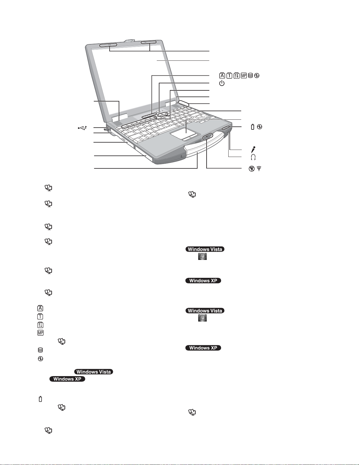
2. Names and Functions of Parts
A
B
C
D
E
G
H
I
J
K
A
L
M
N
I
O
P
F
A :Speaker
Reference Manual “Key Combinations”
B :USB port
Reference Manual “USB Devices”
C :Stylus holder
D :Multimedia pocket
Reference Manual “Multimedia Pocket”
E :Hard disk drive
Reference Manual “Hard Disk Drive”
F :Carrying handle
G :Wireless LAN antenna
<Only for model with wireless LAN>
Reference Manual “Wireless LAN”
H :LCD
<Only for model with touchscreen>
Reference Manual “Touchscreen”
I : LED indicator
: Caps lock
: Numeric key (NumLk)
: Scroll lock (ScrLk)
: Multimedia pocket device status
Reference Manual “Multimedia Pocket”
: Hard disk drive status
: Power status
(Off: Power off/Hibernation, Green: Power on, Blinking green: Sleep/
Standby, Blinking green rapidly:
Cannot power on or resume due to low temperature.)
: Battery status
Reference Manual “Battery Power”
J : Power switch
K :Function key
Reference Manual “Key Combinations”
Q
L :Bluetooth antenna
<Only for model with Bluetooth>
Reference Manual “Bluetooth”
M :Keyboard
N :Touch pad
O :Microphone jack
A condenser microphone can be used. If other types
of microphones are used, audio input may not be possible, or malfunctions may occur as a result.
• When recording in stereo using a stereo microphone:
Click (Start) - [Control Panel] - [Hardware and
Sound] - [Sound] - [Recording] - [Microphone ] [Properties], and then add a check mark for [No Filtering] in [Microphone Enhancements].
Click [start] - [All Programs] - [SoundMAX] - [Control
Panel] and select [Microphone], and then add a check
mark for [No Filtering] in [Microphone Enhancements].
• When using a monaural microphone with a 2-terminal plug:
Click (Start) - [Control Panel] - [Hardware and
Sound] - [Sound] - [Recording] - [Microphone ] [Properties], and then add a check mark for [Voice
Recording] in [Microphone Enhancements].
Otherwise, only audio on the left track will be recorded.
Click [start] - [All Programs] - [SoundMAX] - [Control Panel]
and select [Microphone], and then add a check mark for
[Voice Recording] in [Microphone Enhancements].
Otherwise, only audio on the left track will be recorded.
P :Headphone jack
You can connect headphones or amplified speakers.
When they are connected, audio from the internal
speakers is not heard.
Q :Wireless switch
Reference Manual “Disabling/Enabling Wire-
less Communication” “Wireless LAN” “Bluetooth”
2-1
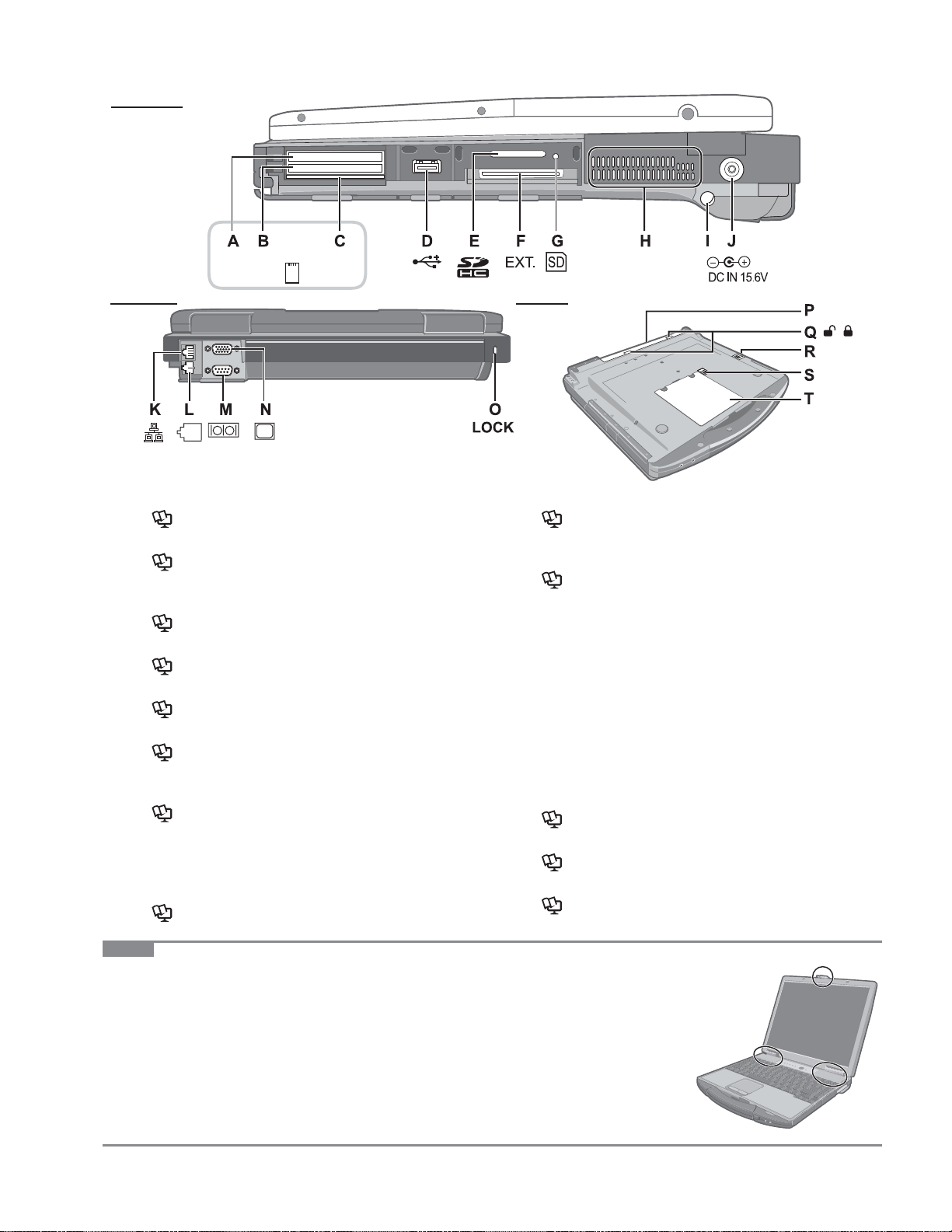
Right side
EX PC
Rear side
A :ExpressCard slot
Reference Manual “PC Card / ExpressCard”
B :PC Card slot
Reference Manual “PC Card / ExpressCard”
C :Smart Card slot
<Only for model with Smart Card slot>
Reference Manual “Smart Card”
D :USB port
Reference Manual “USB Devices”
E :SD Memory Card slot
Reference Manual “SD Memory Card”
F : Expansion bus connector
Reference Manual “Mini Port Replicator”
G :SD Memory Card indicator
(Blinking: During ac cess or a password is requested)
Reference Manual “SD Memory Card”
H :Ventilation hole
I : Stylus holder
J : DC-IN jack
K :LAN port
Reference Manual “LAN”
Bottom
L :Modem port
Reference Manual “Modem”
M :Serial port
N :External display port
Reference Manual “External Display”
O :Security lock
A Kensington cable can be connected.
For further information, read the manual that comes
with the cable.
P :Battery pack
Specified Battery pack: CF-VZSU43A
The battery pack is a consumable item. If you continue
to use a battery pack after it has degraded, problems
may occur. Be sure to replace the degraded battery
pack with a new battery pack of the specified type.
Q :Battery latch
R :Multimedia pocket release button
Reference Manual “Multimedia Pocket”
S :Hard disk drive latch
Reference Manual “Hard Disk Drive”
T :RAM module slot
Reference Manual “RAM Module”
NOTE
This computer contains a magnet and magnetic products at the locations circled in the
illustration at right. Avoid leaving metallic object or magnetic media in contact with
these areas.
2-2
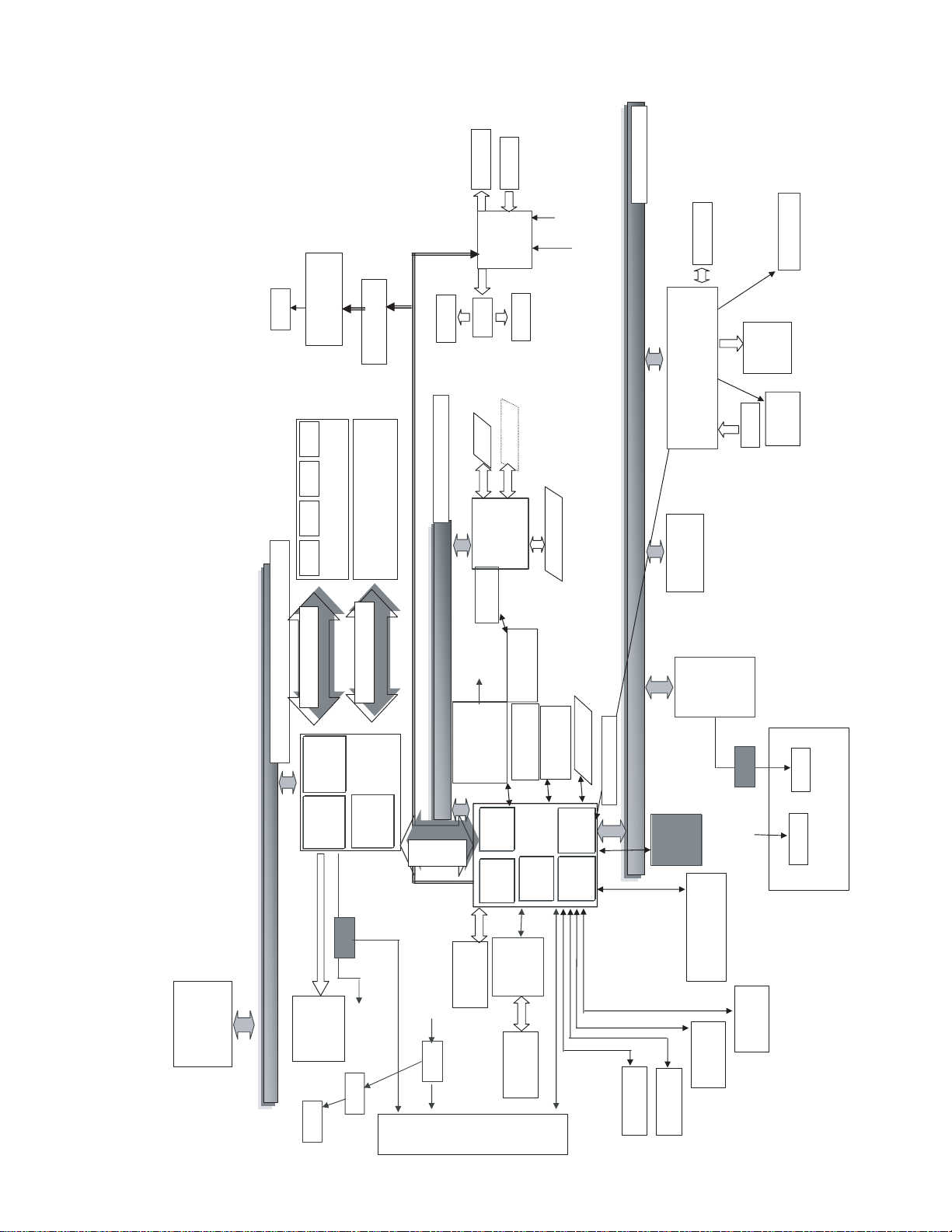
3 Block Diagram
3
b
C
us
33
H
p
A
g
-
p
u
p
3.3V
PM Signals
ress B
PCI Ex
LPC Bus
Touch Pad
EC/KBC
(H8S2117)
17Mbytes/sec
Module
TPM 1.2
Winbond
Super I/O
WPCN381
Int. KB
Buffer
Li-Ion
Battery Charger
Pack
Battery
LED
BKLT
I/O Board
Serial
Ext. MIC
Headphone
Beep
Sound
AD1883
RJ11
Data Modem
Agere or Conexant
MDC1.5 I/F
eaker
S
MP
eaker
S
ODD
M
SD Card
I B
3.3V
it P
2
( DDR2 SDRAM)
SO-DIMM MainMemory
1.05V AGTL+
64bit BUS 1.8V 800MHz
Front side Bus 64bit 1067MHz
SO-DIMM Extension Memory
( DDR2 SDRAM)
2GB
2GB
133Mbytes/sec
HD Audio
3.2Gbytes/sec
3.2Gbytes/sec
64bit BUS 1.8V 800MHz
DRAM
Intel
Interface
Cantiga GM
SmartCard (6612)
PCMCIA
R5C847/853
antenna
GBE
Boazman
Ethernet GBe
Intel 82567LM
TYPE II
Wireless LAN
Kedron 11n
ExpressCard
Robson
FlashCard
Mini Card
e
GBE
SW
1Gbytes/sec x2
2lane
DMI x2
SATA
SATA HDD
160GB 2.5”
PCI
HDA
3-1
Brid
Interface
Bridge
PATA
LPC
Intel
ICH9ME
(1.05V)
IDE
PCIe
Marvell
88SE6101
Multi
PATA
DVD
Bridge
USB 2.0
Interface
Interface
USB
BIOS
25LF032
SPI 8Mbit
Touchscreen
USB 2.0 x2
USB 2.0 x2
Bridge
Host PCI
Graphics
Internal
Analog 0.7Vpp
Internal Core Frequency 2.4GHz
L3 Cache : 3MB Dual Core , EM64 T,VT,LT
L2 Cache : 256KB
Maximum Performance Mode :
FSB 1067MHz Enhanced Speed Step
Penryn POP
Intel
LVDS 1ch
LCD
13.3” XGA
RJ45
SW
CRT
18bit
Trans
PR
CRT
Wide Range Wireless
Bluetooth
Finger Print
CRT

4
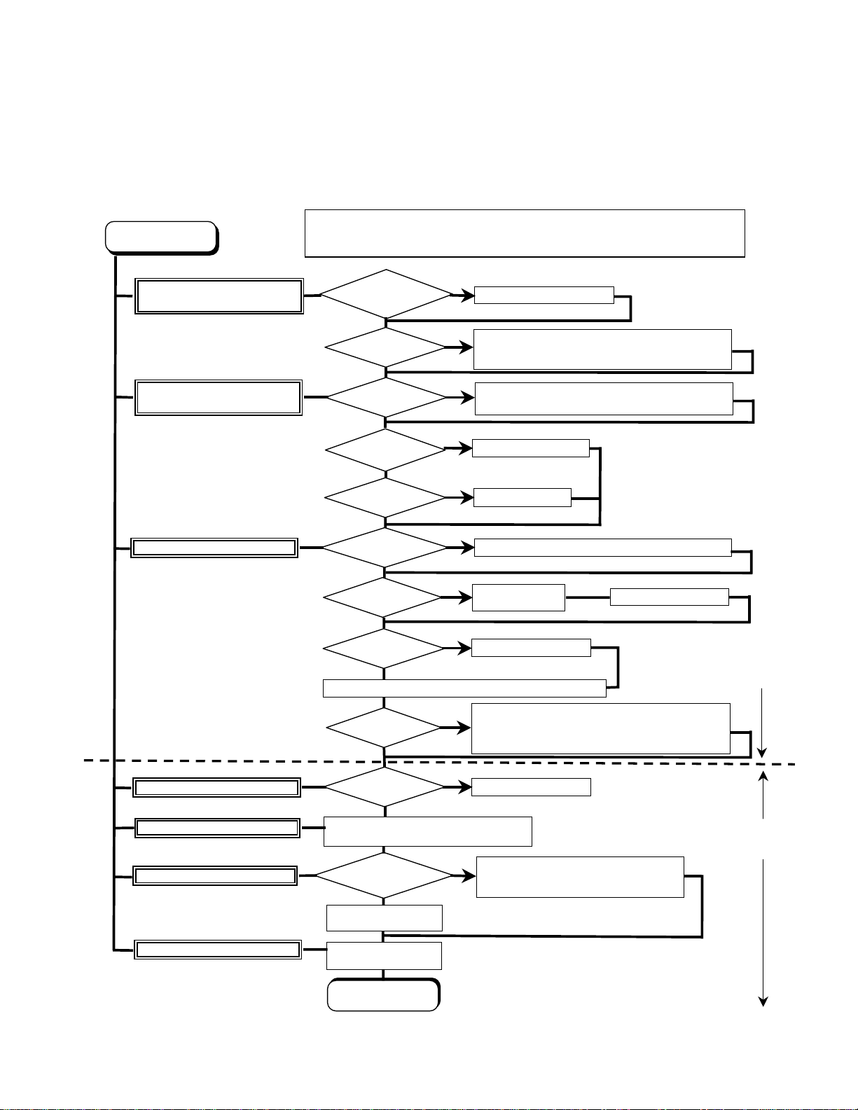
4.1.
4-1
4.2. Troubleshooting
Please take note of the following two points with regard to troubleshooting:
1. Know-how of diagnosis upon occurrence of heavy troubles, e.g. ‘Set cannot be turned ON’, ‘Set fails to start’, ‘No display on
screen’, etc.
2. Explanation of each trouble, mainly symptom of trouble in operation.
● Flow Chart
START
START
Pay attention to the following points when in pursuit of the cause of a troubleshooting.
1. Peripheral apparatus connected with the set should all be removed before operation check.
2. Make sure that cables, boards, etc. are not coming off, and recheck the contact condition.
Set cannot be supplied with current.
Power lamp fails to light up.
Dark display on screen.
Screen fails to display.
Failure in starting
Return set-up utility setpoint to the state of ‘delivery from factory’.
Not displayed properly on screen.
Some or all keys cannot be input.
Make sure of contact of K/B connector in use.
Replace keyboard or main board.
DVD/CD CALL not practicable.
*Clean DVD-ROM drive with an applicator.
Starts but operates unstably.
Replace DVD drive.
Replace main board.
Reinstall HDD.
Replace main board.
AC
Adaptor/Battery
Output voltage
Power lamp
check
Inverter board
LCD back
light lighting
YES
LCD unit
check
BIOS operation
chec
k
Result of
POST
Set-up utility
starting
OK
HDD access
YES
Main board
check
OK
Trouble
symptoms on some
of DVD or CD
OK
YES
OK
OK
YES
OK
YES
NO
NG
NO
NG
NO
NG
NG
NO
NG
NG
Replace AC Adaptor/Battery
Check contact condition of power input terminal. Replace if
defective.
Check Power SW. Replace if defective.
Replace inverter board.
Check inverter cable continuity. Replace if defective
Replace LCD back light.
Replace LCD unit.
Replace main board (Check fuse at power source).
Refer to POST
error code table.
Replace main board.
Check HDD cable connection and continuity.
Replace if defective.
Replace HDD & Reinstall.
Replace main board.
Replace main board
Check if there are any flaws on DVD or CD
NO
media. Since flaws may appear on specifi
media, DVD or CD media can be defective.
Replace main board.
Heavy trouble e.g.,
‘Set cannot be turned
ON’, ‘Set fails to start’,
‘No display on
screen’, etc.
Each kind of
trouble in
operation.
c
START
END
4-2
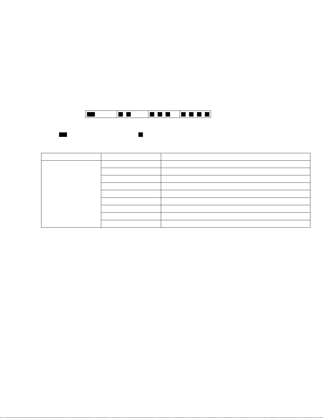
5 Power-On Self Test (Boot Check)
Outline of POST
The set has a boot check function called POST (Power-On Self Test) in it. The condition of the main body is diagnosed by checking
beep sound or error code.
z Start .............Test begins automatically when power switch is set to ON.
z Normal finish .....After memory checking, a beep sound is issued once and the set is placed into automatic stop.
Note: If no error occurs, nothing is displayed. (No display of OK, etc.)
Error Diagnosis by Checking Beep Signal Sound
The beep sound is as follows:
(1 (long sound) -2-3-4)
(Length of bar shows length of sound.)
= long sound (about 0.4 sec.),
z Table of errors classified by beep sounds
Diagnosis Beep signal sound Error message
Main board
(Note) A beep sound is also issued in case of other I/O trouble.
1(long sound)-2 BIOS ROM error
1-2-2-3
1-3-1-1
1-3-1-3
1-3-4-1
1-3-4-3
1-4-1-1
= short sound (about 0.2 sec.), Length between sounds is about 0.1 sec.
BIOS ROM error
RAM error
Keyboard controller error
RAM error
RAM error
RAM error
BIOS ROM error2-1-2-3
Occurrence of unexpected offering2-2-3-1
5-1

6 List of Error Codes
<Only when the port replicator is connected>
The following is a list of the messages that BIOS can display. Most of them occur during
POST. Some of them display information about a hardware device, e.g., the amount of memory
installed. Others may indicate a problem with a device, such as the way it has been configured.
Following the list are explanations of the messages and remedies for reported problems.
If your system displays one of except the messages marked below with an asterisk (*), write
down the message and contact Panasonic Technical Support. If your system fails after you
make changes in the Setup menus, reset the computer, enter Setup and install Setup defaults
or correct the error.
0200 Failure Fixed Disk
Fixed disk in not working or not configured properly. Check to see if fixed disk is attached
properly. Run Setup. Find out if the fixed-disk type is correctly identified.
0210 Stuck key
Stuck key on keyboard.
0211 Keyboard error
Keyboard not working.
0212 Keyboard Controller Failed
Keyboard controller failed test. May require replacing keyboard controller.
0213 Keyboard locked - Unlock key switch
Unlock the system to proceed.
0230 System RAM Failed at offset : nnnn
System RAM failed at offset nnnn of in the 64k block at which the error was detected.
0231 Shadow RAM Failed at offset : nnnn
Shadow RAM failed at offset nnnn of the 64k block at which the error was detected.
0232 Extended RAM Failed at offset : nnnn
Extended memory not working or not configured properly at offset nnnn.
0250 System battery is dead - Replace and run SETUP
The CMOS clock battery indicator shows the battery is dead. Replace the battery and run Setup
to reconfigure the system.
*0251 System CMOS checksum bad - Default configuration used
System CMOS has been corrupted or modified incorrectly, perhaps by an application program
that changes data stored in CMOS. The BIOS installed Default SETUP Values. If you do not
want these values, enter Setup and enter your own values. If the error persists, check the system
battery or contact Panasonic Technical Support.
0260 System timer error
The timer test failed. Requires repair of system board.
0270 Real time clock error
Real-time clock fails BIOS test. May require board repair.
*0280 Previous boot incomplete - Default configuration used
Previous POST did not complete successfully. POST loads default values and offers to run
Setup. If the failure was caused by incorrect values and they are not corrected, the next boot
will likely fail. On systems with control of wait states, improper Setup settings can also terminate POST and cause this error on the next boot. Run Setup and verify that the wait-state
configuration is correct. This error is cleared the next time the system is booted.
0281 Memory Size found by POST differed from EISA CMOS
Memory size found by POST differed from EISA CMOS.
6-1

02D0 System cache error - Cache disabled
Contact Panasonic Technical Support.
02F0: CPU ID:
CPU socket number for Multi-Processor error.
02F4: EISA CMOS not writable
ServerBIOS2 test error: Cannot write to EISA CMOS.
02F5: DMA Test Failed
ServerBIOS2 test error: Cannot write to extended DMA (Direct Memory Access) registers.
02F6: Software NMI Failed
ServerBIOS2 test error: Cannot generate software NMI (Non-Maskable Interrupt).
02F7: Fail - Safe Timer NMI Failed
ServerBIOS2 test error: Fail-Safe Timer takes too long.
device address Conflict
Address conflict for specified device.
Allocation Error for: device
Run ISA or EISA Configuration Utility to resolve resource conflict for the specified device.
Failing Bits : nnnn
The hex number nnnn is a map of the bits at the RAM address which failed the memory test.
Each 1 (one) in the map indicates a failed bit. See error 230,231 or 232 for offset address of the
failure in System, Extended or Shadow memory.
Invalid System Configuration Data
Problem with NVRAM (CMOS) data.
I/O device IRQ conflict
I/O device IRQ conflict error.
Operating System not found
Operating system cannot be located on either drive A: or drive C:. Enter Setup and see if fixed
disk and drive A: are properly identified.
Parity Check 1 nnnn
Parity error found in the system bus. BIOS attempts to locate the address and display it on the
screen. If it cannot locate the address, it displays ????. Parity is a method for checking errors
in binary data. A parity error indicates that some data has been corrupted.
Parity Check 2 nnnn
Parity error found in the I/O bus. BIOS attempts to locate the address and display it on the
screen. If it cannot locate the address, it displays ????.
Press <F1> to resume, <F2> to Setup
Displayed after any recoverable error message. Press <F1> to start the boot process or <F2> to
enter a Setup and change the settings. Write down and follow the information shown on the
screen.
Troubleshooting
6-2

7 Self Diagnosis Test
1
As for the self-diagnosis test(PC-Diagnostic utility) to use this model, a standard test and the
enhancing test by the module of the main body building in are possible.
●Notes To skip BIOS password
Use <Ctrl>+<F10> key to skip BIOS password or authentication of fingerprint.
This key is only for entering DIAG mode. Not available to boot the computer.
If customer set "HDD Lock", the DIAG program cannot perform HDD test.
*This key is for service purpose only. Do not disclose this information to unrelated others.
. Beginning of self-diagnosis test
1-1. Setting of content of setup
1. The power supply of the computer is turned on.
2. " F2 " is pushed on the screen of "Panasonic" while " press <F2 to enter Setup> " is displayed.
3. The setup utility starts and then takes notes of the content of the BIOS setup of present set.
4. " F9 " is pushed, " Yes" is selected on the screen of " Is the default value loaded? ", and " Enter"
is pushed.
5. " F10 " is pushed.
6. " Yes" is selected on the screen of the setup confirmation, and " Enter" is pushed.
7. The computer starts automatically.
Attention
・If the device which can be set is set to "Invalidity" by "Advanced" or "Security" menu, becomes an
error by "PC-Diagnostic utility".
(It is judged that the device which can be set to "Invalidity" by "Main" menu such as "Flat pad" is
normal if the controller operates normally though sets to "Invalidity" by the setup. )
・In the model with built-in DVD of the USB connection, even if DVD is normal, becomes an error if
legacy USB is set to "Invalidity"
1-2. When you execute an automatic test
1. "Ctrl" + "F7" is pushed while the "Panasonic" start screen is displayed after the computer is started.
2. The test of all devices begins automatically by "PC-Diagnostic utility" 's starting.
Attention
・It is a test which the customer who bought PC can execute. (As for HDD, the enhancing test is also
possible.)
・A flat pad does not work for a while after starting "PC-Diagnostic utility".
・The movement of a flat pad might become abnormal If after RAM begins from the CPU/System
test, a flat pad will be operated in about 30 seconds. In that case,restarts pushing"Alt" + "Ctrl" +
"Del" key. Or, please start "PC-Diagnostic utility" again after doing the power supply switch in the
slide, and turning off the power supply.
1-3. When you execute the enhancing test
1. Please let me discontinue diagnosing clicking to end an automatic test.
2. Please click on the character of "D" "PC-Diagnostic utility" on the screen while pushing both of right
"Shift" and left "Shift" keys.
3. All devices which can select the enhancing test make the setting of the enhancing test possible.
4. The district device is made"FULL" display (enhancing test).
5. The test begins clicking .
*Please refer to item 4 for the error result of each test and the division of the breakdown part.
7-1

2. Operation of PC-Diagnostic Utility
-Only the device which can be inspected on the entire screen is displayed.
-The item does not appear when the device of wireless LAN etc. is not physically connected.
-The movement of the item must use an arrow key or a flat pad.
-As for the device under the diagnosis, blue and yellow are alternately displayed at the left of the icon.
- The diagnosis result of the device greens at the left of the icon when it is normal, and becomes red when
abnormal.
-When the test of all devices ends, the test result is displayed under the right of the screen.
-Please click while diagnosing when being stop on the way by the time the test of all devices ends.
-Please click when you restart "PC-Diagnostic utility".
*Each device is tested from the beginning, and it is not possible to restart on the way.
-When the test of all devices ends, the test result is displayed under the right of the screen.
7-2

2-1. Selection of tested device
-To test only a specific device, "Test" and "Do not test" of each device can be selected.
-The device which can select the enhancing test changes in order of "The standard is tested" and "Do not
test" whenever the device icon is clicked.
Start the standard test Do not test
Please begin testing clicking if the selection of the tested device ends.
2-2. "PC-Diagnostic utility" End method
When of "Close" on the right of the screen is clicked, the computer reactivates automatically. Or, the
power supply switch is done in the slide and the power supply is turned off.
2-3. The content of the setup is returned to the setting of the user
1. Turned on the computer.
2. "F2" is pushed on the screen while "Press<F2>to enter Setup" is displayed of "Panasonic".
3. Push "F10", and on the screen of "Is the change in the setting preserved and do end?"and then "Yes"
is selected, and "Enter" is pushed.
4. The computer reactivates automatically.
5. The end option is chosen by the start menu, and the power supply of the computer is turned off.
Standard at test time
All devices other than RAM and HDD ---------- about 1 minute
RAM standard test ----------------------------------- 1 - 2 minutes
HDD standard test ----------------------------------- 2 - 3 minutes
HDD enhancing test (60GB) ---------------------- about 40 minutes
Ex.The standard when the standard <all device> is tested becomes 1+2+3=6 minutes.
■There is greatly a difference from RAM test when the memory is increased according to the performance
of the memory occasionally.
■Moreover, when the main body of PC under the test is a high temperature, it occasionally takes time.
■There is greatly a difference from HDD according to the performance of the drive occasionally.
7-3

●To skip BIOS password
Use <Ctrl>+<F10> key to skip BIOS password or authentication of fingerprint.
This key is only for entering DIAG mode. Not available to boot the computer.
If customer set "HDD Lock", the DIAG program cannot perform HDD test.
*This key is for service purpose only. Do not disclose this information to unrelated
others.
7-6
 Loading...