

Panasonic BL-C111A - Network Camera - Pan, BL-C131A Service Manual
BL-C111A
BL-C131A
(for U.S.A.)
ORDER NO. KMS0701303CE
F15
Network Camera
© 2007 Panasonic Communications Co., Ltd. All
rights reserved. Unauthorized copying and distribution is a violation of law.

BL-C111A /BL-C131A
TABLE OF CONTENTS
PAG E PAG E
1Warning--------------------------------------------------------------3
1.1. Battery Caution ---------------------------------------------3
1.2. About Lead Free Solder (PbF: Pb free) --------------3
1.3. For Service Technicians----------------------------------6
1.4. Trademarks --------------------------------------------------6
2 Specifications ------------------------------------------------------7
2.1. Internal Memory Capacity for Buffered Images-----8
3Features--------------------------------------------------------------9
4 Technical Descriptions---------------------------------------- 10
4.1. Main Board------------------------------------------------- 10
4.2. RF Block(C131A only) ---------------------------------- 16
5 Location of Controls and Components------------------ 17
6 Installation Instructions---------------------------------------18
7 Operation Instructions ---------------------------------------- 20
7.1. Preparation ------------------------------------------------ 20
7.2. Connection------------------------------------------------- 21
7.3. Setup Guide ----------------------------------------------- 22
8 Troubleshooting Guide---------------------------------------- 24
8.1. Starting Up Operation ----------------------------------- 24
8.2. Indicator view Check ----------------------------------- 26
8.3. LAN Block Check----------------------------------------- 27
8.4. Camera Block Check------------------------------------ 30
8.5. Power Supply Block Check ---------------------------- 31
8.6. Other Operation Check --------------------------------- 32
8.7. Pyroelectric Infrared Sensor Check ----------------- 33
8.8. Sound Block Check-------------------------------------- 34
8.9. RF Block Check(BL-C131A) -------------------------- 35
8.10. The Inspection After The Repair --------------------- 36
8.11. Diagnosis NG Check ------------------------------------ 36
8.12. In Case Where the Main Board Is Replaced
and a New MAC Address Label Is Used ----------- 37
8.13. In Case Where the RF Board Is
Replaced(C131A only)---------------------------------- 37
8.14. Update Firmware ----------------------------------------- 37
8.15. How To Change MAC Address Label--------------- 38
8.16. How to Replace a Flat Package IC ------------------ 39
9 Disassembly and Assembly Instructions--------------- 40
9.1. Disassembly Instructions(BL-C111A) --------------- 40
9.2. Disassembly Instructions(BL-C131A) --------------- 44
10 Maintenance ------------------------------------------------------ 49
10.1. Cleaning ---------------------------------------------------- 49
11 Factory Setting--------------------------------------------------- 50
11.1. Resetting the Camera----------------------------------- 50
11.2. Resetting the Camera Using the FACTORY
DEFAULT RESET Button ------------------------------50
12 Block Diagram ---------------------------------------------------51
13 Schematic Diagram--------------------------------------------- 52
13.1. For The Schematic Diagram -------------------------- 52
13.2. Schematic Diagram-------------------------------------- 53
13.3. Waveform --------------------------------------------------62
14 Printed Circuit Board ------------------------------------------ 65
14.1. Main Board (Component View) ----------------------- 65
14.2. Main Board (Bottom View) ----------------------------- 66
14.3. Lens Board (Component View) ----------------------- 67
14.4. Lens Board (Bottom View) ----------------------------- 67
14.5. I/O Board (Component View) ------------------------- 68
14.6. I/O Board (Bottom View) ------------------------------- 69
14.7. Sub Board (Component View) ------------------------70
14.8. Sub Board (Bottom View)------------------------------ 70
15 Appendix Information of Schematic Diagram -------- 71
15.1. Terminal Guide of ICS, Transistors and
Diodes ------------------------------------------------------ 71
16 Exploded View and Replacement Parts List----------- 72
16.1. Cabinet and Electrical Parts Location(BLC111A)------------------------------------------------------ 72
16.2. Cabinet and Electrical Parts Location(BLC131A) ----------------------------------------------------- 73
16.3. Accessories and Packing Materials(BLC111A)------------------------------------------------------ 74
16.4. Accessories and Packing Materials(BLC131A) ----------------------------------------------------- 75
16.5. Replacement Parts List (BL-C111A) ---------------- 76
16.6. Replacement Parts List (BL-C131A)---------------- 80
2
BL-C111A/BL-C131A
1Warning
1.1. Battery Caution
Danger of explosion if the battery is replaced incorrectly. Replace only with the same or equivalent type recommended by the
manufacturer. Discard used batteries according to following caution:
Disposal or transportation of lithium batteries should be performed by permitted, in accordance with federal, state and local
guidelines.
A battery continues to have no transportation limitations as long as it is separated to prevent short circuits and packed in strong
packaging.
Commercial firms that dispose of any quantity of lithium cells should have a mechanism in place to account for their ultimate disposition. This is a good practice for all types of commercial or industrial waste.
When the lithium battery is exchanged, the clock settings are cleared. In this case, make clock settings again.
Recommend Type Number:
CR2032/H9B (BAT1) Manufactured by MATSUSHITA
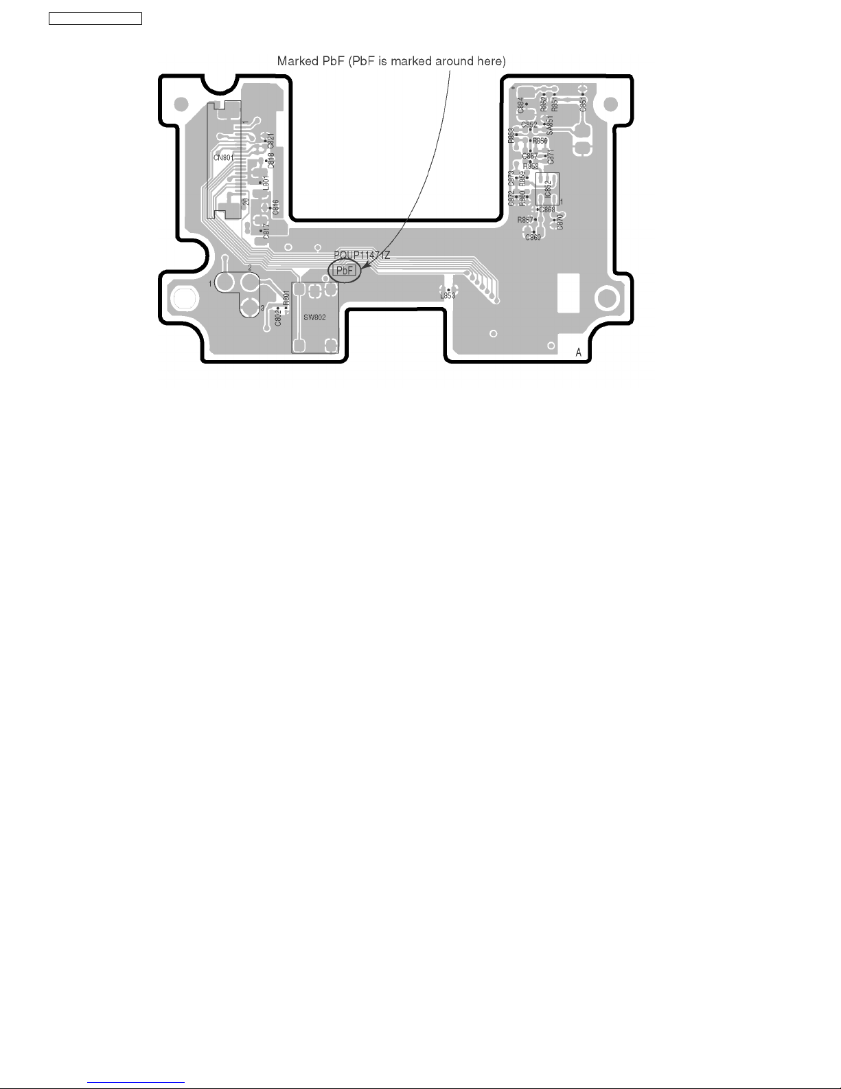
1.2. About Lead Free Solder (PbF: Pb free)
Note:
In the information below, Pb, the symbol for lead in the periodic table of elements, will refer to standard solder or solder that contains lead.
We will use PbF solder when discussing the lead free solder used in our manufacturing process which is made from Tin, (Sn),
Silver, (Ag), and Copper, (Cu).
This model, and others like it, manufactured using lead free solder will have PbF stamped on the PCB. For service and repair
work we suggest using the same type of solder.
Caution
• PbF solder has a melting point that is 50° F ~ 70° F (30° C ~ 40° C) higher than Pb solder. Please use a soldering iron with temperature control and adjust it to 700° F ± 20° F (370° C ± 10°C).
• Exercise care while using higher temperature soldering irons.:
Do not heat the PCB for too long time in order to prevent solder splash or damage to the PCB.
• PbF solder will tend to splash if it is heated much higher than its melting point, approximately 1100°F, (6 0 0 °C).
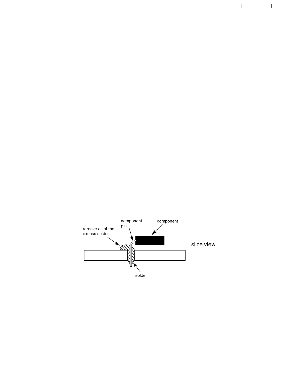
• When applying PbF solder to double layered boards, please check the component side for excess which may flow onto the
opposite side (See figure, below).
3
BL-C111A /BL-C131A
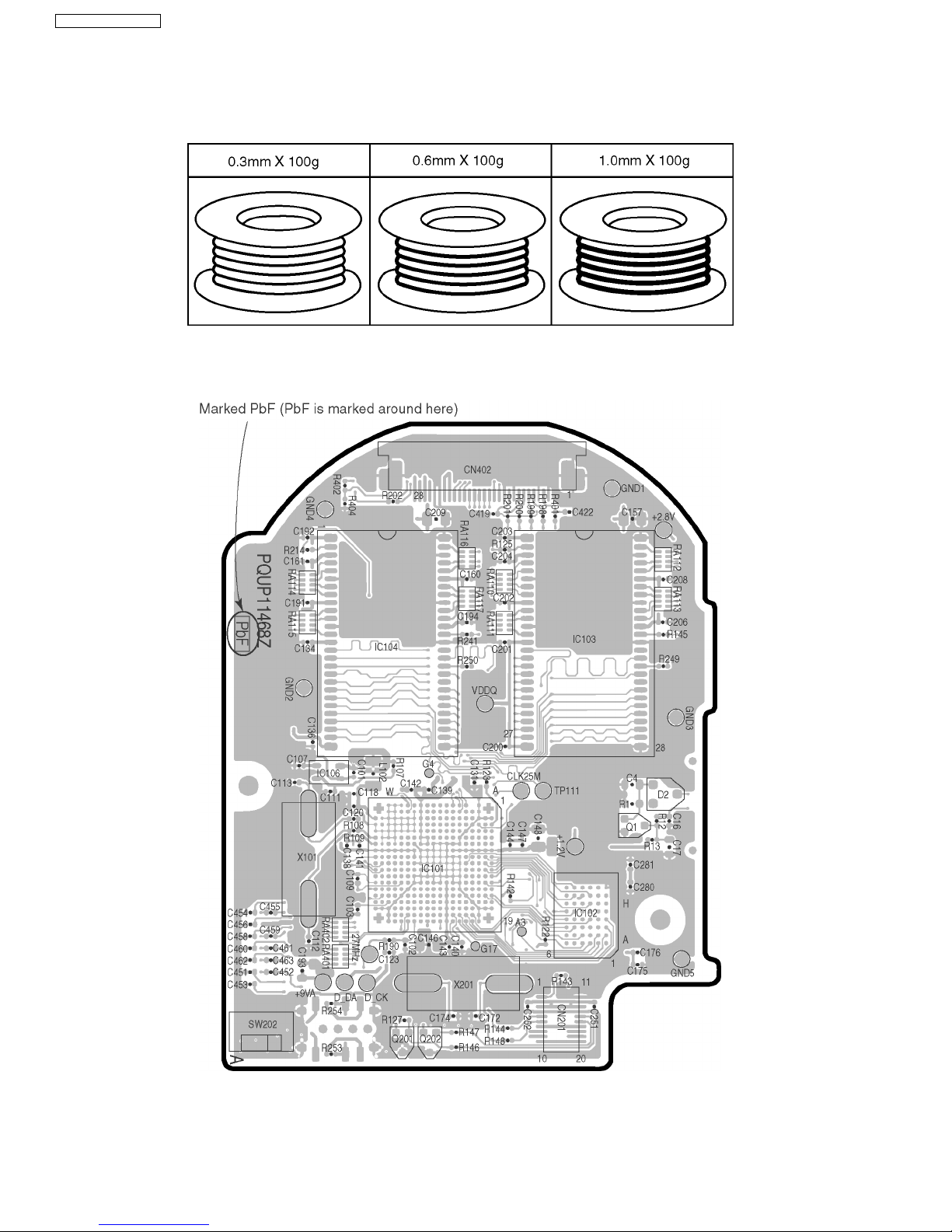
1.2.1. Suggested PbF Solder
There are several types of PbF solder available commercially. While this product is manufactured using Tin, Silver, and Copper,
(Sn+Ag+Cu), you can also use Tin and Copper, (Sn+Cu), or Tin, Zinc, and Bismuth, (Sn+Zn+Bi). Please check the manufacturer’s specific instructions for the melting points of their products and any precautions for using their product with other materials. The following lead free (PbF) solder wire gauge are recommended for service of this product: 0.3mm, 0.6mm and 1.0mm.
1.2.2. How to Recognize That Pb Free Solder is Used
MAIN BOARD
4
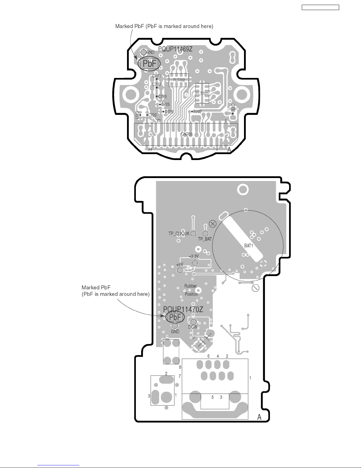
LENS BOARD
I/O BOARD
BL-C111A/BL-C131A
5
BL-C111A /BL-C131A
SUB BOARD
1.3. For Service Technicians
ICs and LSIs are vulnerable to static electricity.
When replacing, the following precautions will help to prevent recurring malfunctions.
1. Cover the plastic parts with aluminum foil.
2. Ground the soldering irons.
3. Use a conductive mat on the work-table.
4. Do not grasp IC or LSI pins with bare fingers.
1.4. Trademarks
• Adobe and Acrobat are either registered trademarks or trademarks of Adobe Systems Incorporated in the United States and/or
other countries.
• Ethernet is a registered trademark of Xerox Corporation in the United States and/or other countries.
• Microsoft, Windows and Active X are either registered trademarks or trademarks of Microsoft Corporation in the United States
and/or other countries.
• Pentium is a registered trademark of Intel Corporation or its subsidiaries in the United States and other countries.
• Screen shots reprinted with permission from Microsoft Corporation.
All other trademarks identified herein are the property of their respective owners.
6

2 Specifications
Camera Specifications
Items Specifications
Zoom 10x (by area) digital zoom
Pan/Tilt Angle Pan: -50° to +50°, Tilt: -40° to +10°
Number of Pixels 1/6 inch CMOS sensor, 320,000 pixels
Illuminance 10-10,000 lx (3-10,000 lx when in Color Night View mode)
White Balance Auto/Manual/Hold
Lens Brightness 9 steps
Focus Fixed, 0.3 m-Infinity
Aperture (F No.) F2.8
Horizontal Viewing Angle 49°
Exposure Auto
Other Specifications
Items Specifications
Image Compression JPEG (3 levels), MPEG-4
Image Resolution 640 x 480, 320 x 240, 192 x 144
Buffered Images
Audio Communication Camera to PC
Audio Compression Format ADPCM 32 kbps
Audio Bandwidth 300 Hz-3.4 KHz
Audio Reception Method ActiveX
Audio Reception Decoding ActiveX
Audio Input Built-in microphone
Frame Rate
Communication Protocols IPv4/IPv6 Dual-Stack
Image Buffer/Transfer Triggers Timer, Sensor, Motion Detection
Image Transfer Method
Wired LAN Interface 10Base-T/100Base-TX Ethernet RJ-45 connector
Sensor Detection Method Pyroelectric Infrared Sensor
Sensor Detection Range
Indicator Display Power
Dimensions (W x H x D) 74 mm x 98 mm x 73 mm
Weight (Main Unit Only) BL-C111A: 180 g (0.4 lb.)
Power Supply AC adaptor: Input 100-240 V AC, 50/60 Hz
Power Consumption BL-C111A: About 2.7 W (4.0 W during pan/tilt scan)
Operating Temperature Operation: +5 °C (+41 °F) to +40 °C (+104 °F)
Operating Humidity Operation: 20 %-80 % (no condensation)
*1
*2
*5
About 250 frames (320 x 240, standard image quality) with time display
Max. 30 frames/second (640 x 480*3, 320 x 240, 192 x 144)
IPv4:
TCP, UDP, IP, HTTP, FTP, SMTP, DHCP, DNS, ARP, ICMP, POP3, NTP, UPnP
RTP, RTSP, RTCP
IPv6:
TCP, UDP, IP, HTTP, FTP, SMTP, DNS, ICMPv6, POP3, NDP, NTP, RTP, RTSP, RTCP
*4
SMTP
, FTP, HTTP
Horizontal: About 30°
Vertical: About 85°
Distance: About 5 m (16 feet 5 inches) when in a 20 °C (68 °F)
environment
Network Communication
Camera Operation
Ethernet Link
Sensor Detection
(2 15/16 inches x 3 7/8 inches x 2 7/8 inches)
BL-C131A: 210 g (0.46 lb.)
Output 9 V DC, 750 mA
BL-C131A: About 4.7 W (6.0 W during pan/tilt scan)
Storage: +0 °C (+32 °F) to +50 °C (+122 °F)
Storage: 20 %-90 % (no condensation)
BL-C111A/BL-C131A
TM
, SMTP Authentication,
Items Specifications
Communication Standard IEEE 802.11b, 802.11b/g, 802.11g exclusive
Data Transfer Mode IEEE 802.11b: Direct Sequence Spectrum Spread (DS-SS)
IEEE 802.11g: Orthogonal Frequency Division Multiplexing (OFDM)
Frequency Range 2.412-2.462 GHz
Channel 1-11
Security SSID, WEP (64/128/152 bit), WPA-PSK (TKIP), WPA2-PSK (AES)
Wireless Specifications (BL-C131A Only)
7

BL-C111A /BL-C131A
*1) See 2.1. Internal Memory Capacity for Buffered Images for details.
*2) Frame rate may slow down depending on the network environment, PC performance, image quality, when viewing dark
images, etc.
*3) 30 frames/second is not possible when viewing MJPEG images at 640 x 480 resolution.
*4) The camera supports POP Before SMTP Authentication and SMTP Authentication. PLAIN, LOGIN, and CRAM-MD5 SMTP
Authentication are supported.
*5) When the temperature is 20 °C (68 °F)
2.1. Internal Memory Capacity for Buffered Images
The camera‘s internal memory can buffer images according to the table below.
Note
• All values are approximate.
JPEG images (videos and still images)
Resolution Specification Snapshot Image Quality
Favor Clarity Standard Favor Motion
640 x 480 File Size 50 KB 50 KB 35 KB 27 KB
No. of Images (Saved to PC) 80 110 150
320 x 240 File Size 25 KB 25 KB 16 KB 10 KB
No. of Images (Saved to PC) 160 250 410
192 x 144 File Size 10 KB 10 KB 7 KB 5 KB
No. of Images (Saved to PC) 410 590 830
MPEG-4 videos
For information about MPEG-4 image capacity, see the Panasonic Network Camera website at
http://panasonic.co.jp/pcc/products/en/netwkcam/.
8

BL-C111A/BL-C131A
3 Features
On-site and remote camera monitoring
Camera images can be monitored from a PC, both on-site and over the Internet. You can even use your mobile phone to view
still images when you’re out of the house.
MPEG-4 and Motion JPEG (MJPEG) support
Live camera images can be viewed and buffered (i.e., stored in memory) in both MPEG-4 and JPEG (MJPEG) formats, allowing
you to select the video format that best suits your needs.
Audio features
The camera features a built-in microphone that allows you to monitor the audio while viewing live camera images using your PC.
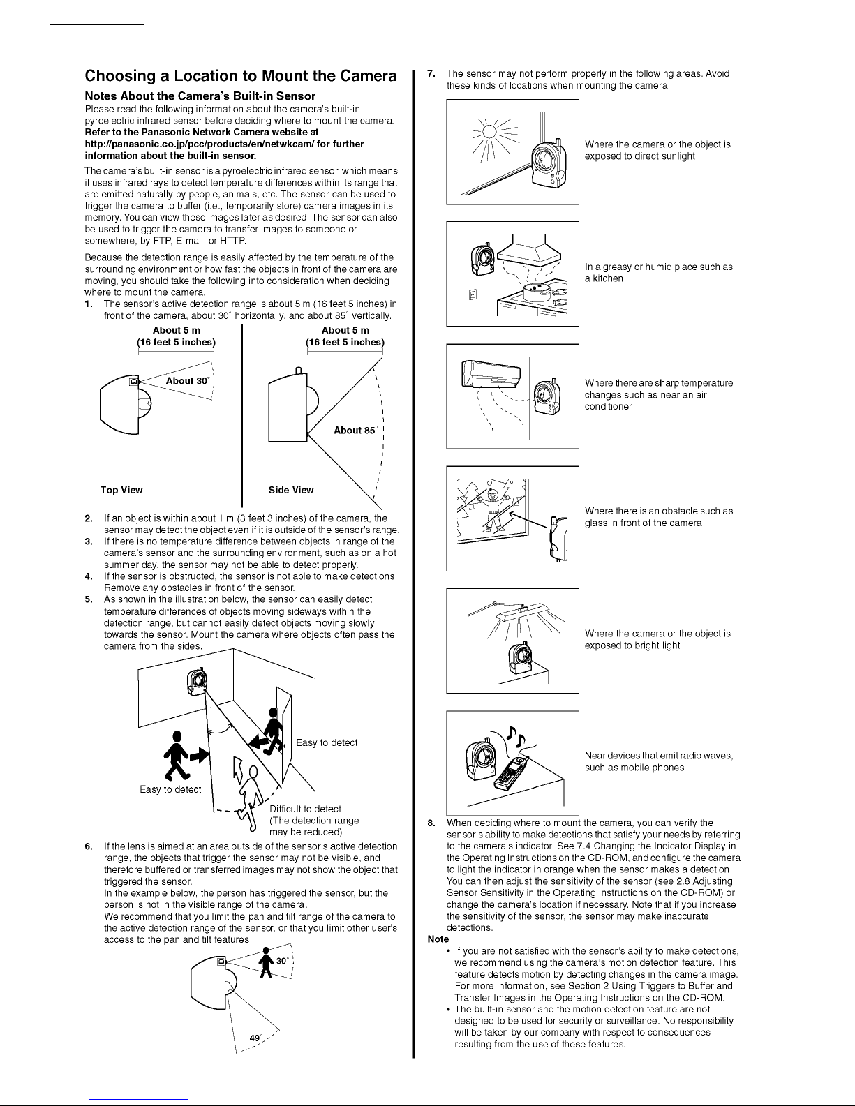
Built-in sensor (human detection sensor)
The camera features a built-in pyroelectric infrared sensor, which uses infrared rays to detect temperature differences within its
range that are emitted naturally by people, animals, etc. The sensor can be used to trigger the camera to buffer (i.e., temporarily
store) camera images in its memory. You can view these images later as desired. The sensor can also be used to trigger the
camera to transfer images to someone or somewhere, by FTP, E-mail, or HTTP.
Motion detection feature
The camera’s motion detection feature allows you to buffer or transfer camera images when the camera detects motion in the
camera image.
Camera image buffering, playback, and sharing
Camera images can be automatically buffered at specific times, when the camera’s sensor is triggered, or when the camera
detects motion. You can program the camera to buffer these camera images, and then you can play back these images later
while accessing the camera or save them to your PC. You can also program the camera to transfer images by E-mail or upload
them to an FTP or HTTP server as they are being buffered.
Digital zoom
When viewing camera images from a PC, you can zoom up to 10X (by area) and get a closer look. You can use your mouse to
zoom in and out simply.
Protecting your privacy
Simply press the camera’s PRIVACY button to hide the lens from view and protect your privacy. You can even activate the privacy mode while away from home.
TM
UPnP
Viewnetcam.com support
Multi-language support
Wireless connectivity (BL-C131A only)
support
When connecting the camera to a UPnPTM compatible router, the camera’s network settings can be automatically configured,
making setup quick and easy.
After registering your camera with the Viewnetcam.com service, you can access the camera while away from home using an
easy to remember Internet address of your choosing, such as bob.viewnetcam.com.
The most commonly used camera pages can be displayed in English, French, German, Italian, Spanish, Russian, Simplified
Chinese, Korean, and Japanese. All camera pages can be displayed in English, French, Simplified Chinese, and Japanese.
The BL-C131A supports wireless standards IEEE 802.11b and IEEE 802.11g, giving you the option of using the camera in either
wired or wireless mode. When used in wireless mode, WEP, WPA-PSK(TKIP), and WPA2-PSK(AES) support ensures that
access to the camera is secure.
9

BL-C111A /BL-C131A
4 Technical Descriptions
4.1. Main Board
4.1.1. CPU Block
CPU (IC101)
Operating Power Supply: 3.3V (for I/O) 1.2V (for Core)
Package: 344 pin LGA
Outline of Operation: This LSI encodes a picture signal input from a camera into a JPEG or an MPEG4 format and an audio signal input from a microphone into a G726 format, and then it distributes the data to the terminal on the IPV4 or IPV6 network
using the network server function achieved by processing the software of a built-in processor.
CMOS sensor (IC701) and Real Time Clock IC (IC3) on the Lens Board are accessed by I2C I/F. Ethernet PHY (IC105) is
accessed by MII (Media Independent Interface) I/F.
FLASH MEMORY (IC102)
Operating Power Supply: +3.3V
Package: 48 pin Ball DGA
Capacity: 64Mbit
Access Time: 60ns
Outline of Operation: Stores programs for CPU operation, MAC address and customer setup data. Version up is available from
Ethernet I/F.
SDRAM (IC103,IC104)
Operating Power Supply: +3.3V
Package: 54 pin TSOP
Capacity: 64Mbit
Outline of Operation: Stores the memory for CPU work and temporary saved images.
RESET IC (IC106)
Reset voltage: 2.9V
Package: 4 pin SOP
Outline of Operation: When 3.3V power starts up, it emits about 150ms reset pulse after detecting 2.9V.
Clear Setting Button (SW802)
Outline of Operation: It is possible to bring back the setting value of a Network Camera to a factory-shipments state, when you
push.
GPI0
• Motor (PAN/TILT) Operation
• Clear Setting SW
• Privacy Mode SW
•I2C
•LED
• Pyroelectric Infrared Sensor
10
BL-C111A/BL-C131A
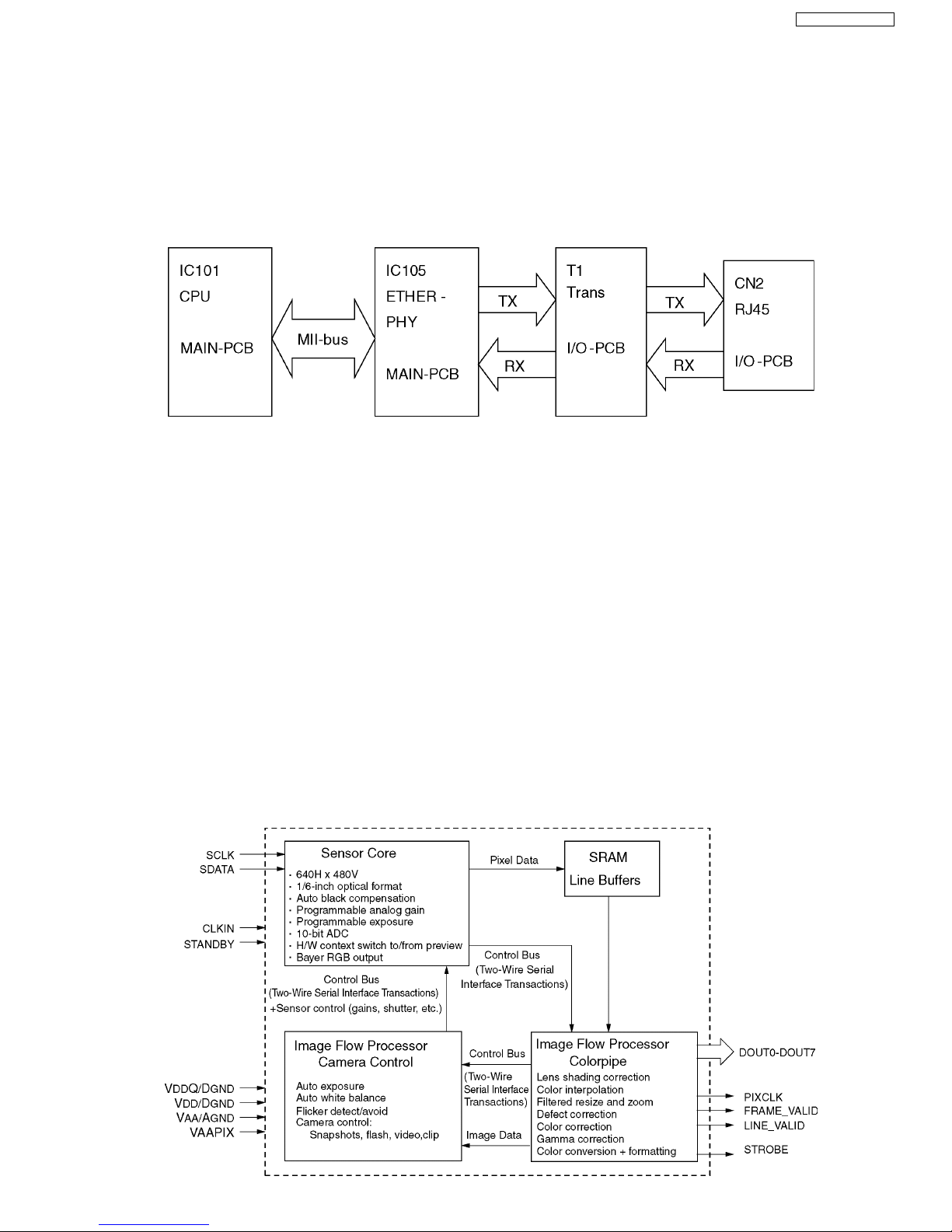
4.1.2. LAN Block
Consists of IC101 (CPU), IC105 (ETHER-PHY), T1 (Trans) and CN2 (RJ45).
T1 (Trans) insulates sets and Ethernet.
IC101 (CPU) and IC105 (ETHER-PHY) are connected by a signal called MIIBus which it makes it possible to transmit/receive
Ethernet data.
IC105 has Auto Negotiation Function which changes 100BASE-T or 10BASE-TX automatically.
Transmitting Operation
Electric signal from IC101 is changed to Ethernet data on IC105 and it is sent through T1 from CN2.
Receiving Operation
Ethernet data from CN2 is change to electrical signal on IC105 and it is received by IC101.
4.1.3. Camera Block
<Basic Circuit Operation>
This CMOS image sensor which consolidates sensor section and image process DSP consists of one chip. Each pixel which
has a micro lens for increased sensibility. It changes optical energy to analogue voltage. After that, analogue pixel voltage is
converted into digital using the 10 bit AD Converter (ADC). At that time, Correlated Double Sampling (CDS) dramatically
decreases Formulaic Pattern Noise (FPN).
Analogue pixel voltage data which is converted to digital is finished using Gammacorrection, Color Correction and Color Space
Conversion. Those signals are sent out as digital format 8bit span Y/UV with PCLK, Hsync and Vsync signals as a timing interface. In addition, the Image Processing Function of AE (Auto Iris) and AWB (Auto White Balance) is installed and it is automatically operated following an algorithm in the chip.
Exposure control (Auto Iris) is adjusted by shutter speed.
Setting up of each chip register is set at I2C by CPU (IC101) on Main Board.
CMOS color image sensor module (IC701)
Operating Power Supply: +2.8V It is supplied by Main Board. (3 Terminal Regulator IC51)
Package: 20pin module
Image Sensor and its Process Circuit are installed.
Available Number of Pixels: 640 x 480 pixels
Image Area: 1/6 inch Optical Size
Color Filter: RGB Beyer Alignment
Input Clock: 27 MHz (It is supplied by IC101 of Main Board)
11
BL-C111A /BL-C131A
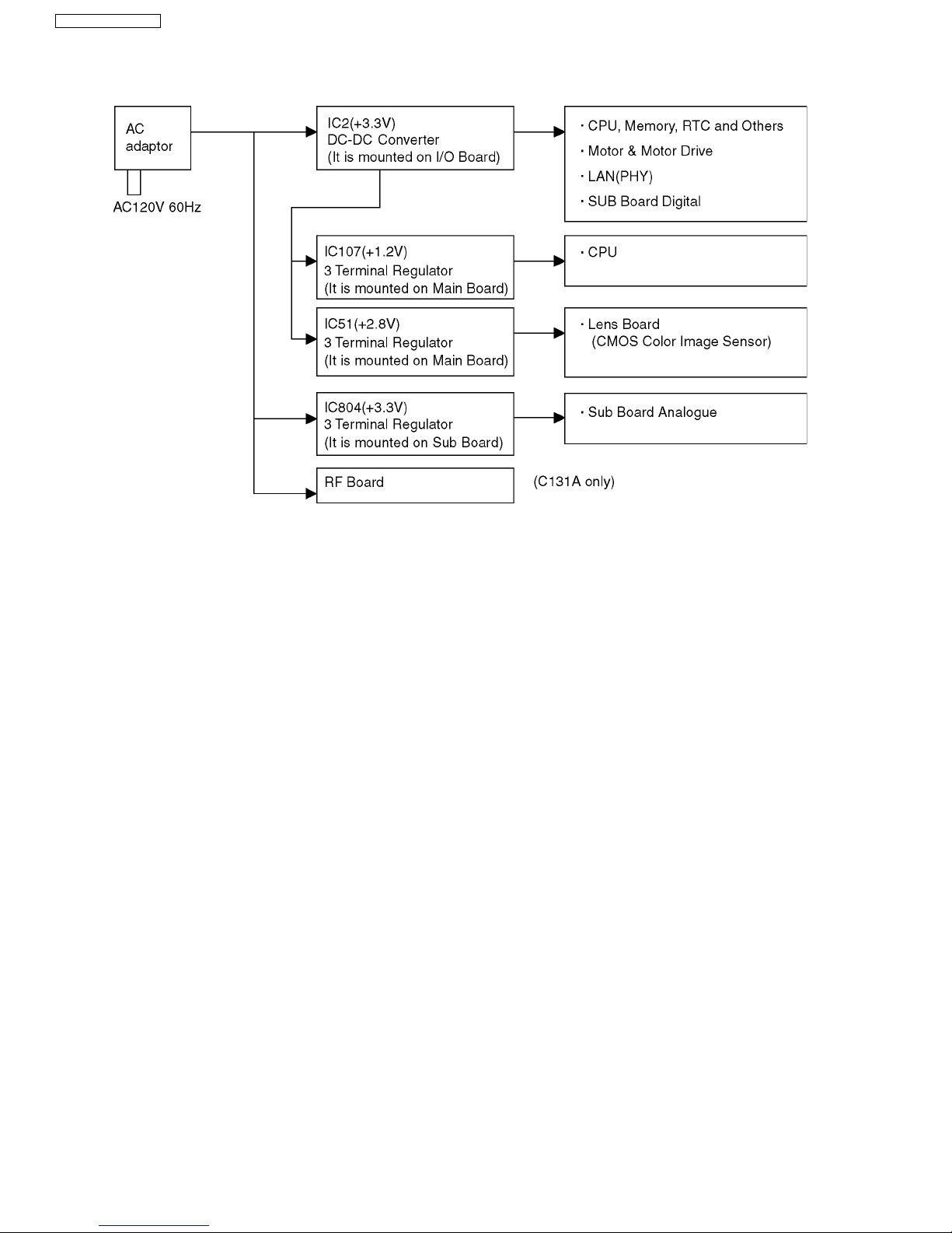
4.1.4. Power Supply Block
Power Supply Block provides power that each block consumes.
Input is DC 9V/750mA from AC adaptor. The circuit diagram and output voltage are showed as below.
12
4.1.5. RTC
Real Time Clock (IC3)
Operating Power Supply: 3.3V (3V battery for back up)
Package: 8 pin SOP
Outline of Operation: Stores Clock Data and resonates 32.768 KHz Clock Signal.
Backup Battery provides power when power supply is out.
Lithium Battery (BAT1)
Output Voltage: 3V
Capacity: 220mAh
Outline of Operation: A backup power supply for Real Time Clock (IC3).
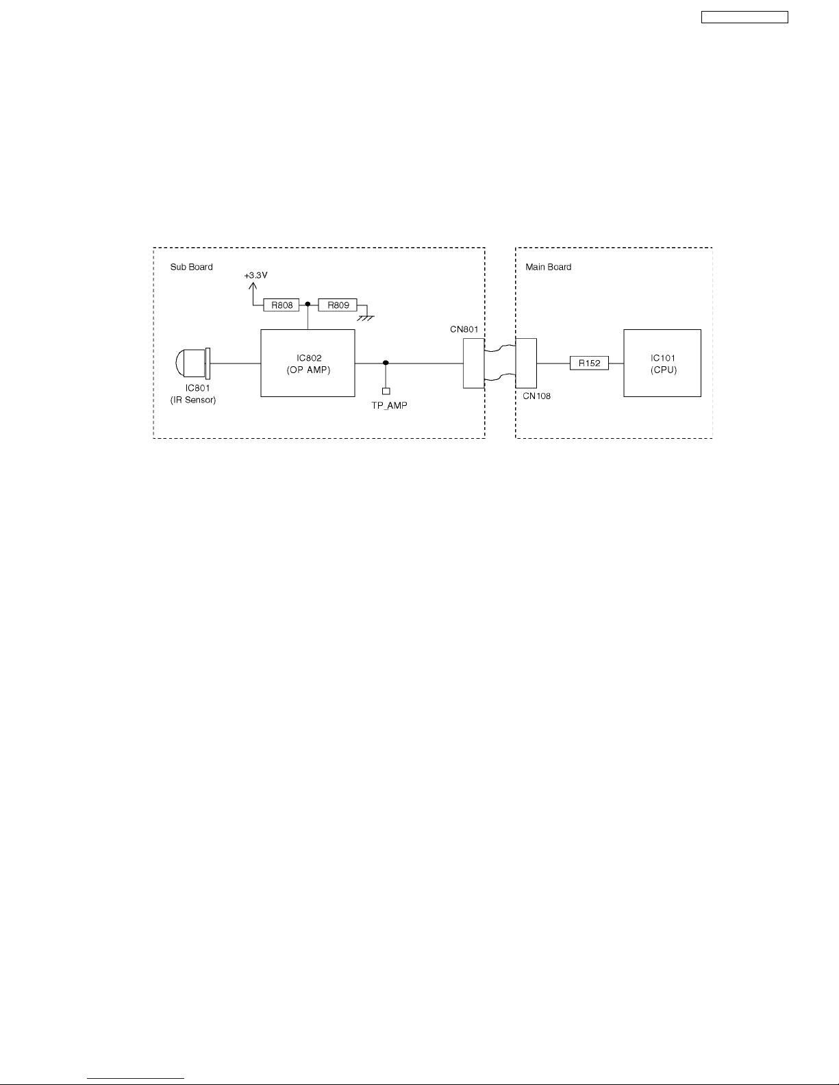
4.1.6. Pyroelectric Infrared Sensor Block
BL-C111A/BL-C131A
Pyroelectric Infrared Sensor (IC801)
Operating Power Supply: +3.3V
Package: 3 pin Board Insertion Type
Changes temperature variation into analogue signal which it emits, when a heat source, such as a person, comes into detection
area.
The analogue signal is amplified by Operational Amplifier (IC802).
2 Circuits Built-in Operational Amplifier (IC802)
Operating Power Supply: +3.3V
Package: 8 pin SSOP
Amplifies analogue signal from Pyroelectric Infrared Sensor (IC801).
Operation of Pyroelectric Infrared Sensor
1. Pyroelectric Infrared Sensor (IC801) emits analogue signal, when a heat source, such as a person, moves into the detection
area.
2. Above signal is amplified by Operation Amplifier (IC802) which emits analogue signal.
3. Above signal is input to AD of CPU (IC101) and the signal amplitude exceeds the specified voltage range, a reaction occurs.
13
BL-C111A /BL-C131A
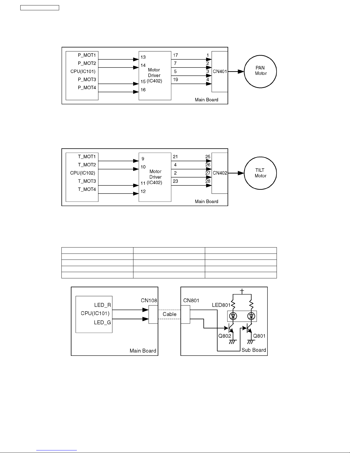
4.1.7. PAN Control Block
A pan motor operates, when CPU (IC101) on a Main Board controls the Motor Driver IC (IC402) on the same board.
A Constant Voltage Bipolar Drive System is employed. The Voltage of Motor Power (VM) is 3.3V. ø15 Stepping Motors are
employed.
4.1.8. TILT Motor Control Block
A Tilt motor operates, when CPU (IC101) on a main board controls the motor driver IC (IC402) on the same board.
A Constant Voltage Bipolar Drive System is employed. The Voltage of Motor Power (VM) is 3.3V.
employed.
ø15 Stepping Motors are
4.1.9. LED Control Block
LED is controlled by CPU which is mounted on Main Board. Control data is input into LED Control Circuit which is mounted on
Sub Board. (Three color LED is employed.)
LED_R LED_G Color of LED
LLOFF
L H Green
HLRed
H H Orange
14
BL-C111A/BL-C131A
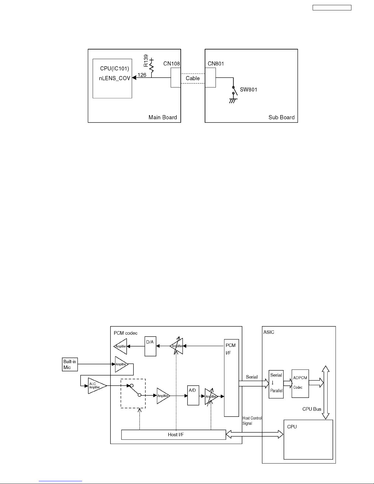
4.1.10. Privacy Mode Control Circuit
Privacy Mode is a function to protect privacy so that a lens may be concealed in a cover part by pushing the Privacy Mode
switch (SW801) and the picture may not be seen.
CPU detects condition of SW801.
4.1.11. Sound Block
Microphone(MIC851)
Input sound.
ALC Amplifier (IC852)
Power Supply: 3.3V
Amplifier for Auto Level Control
PCM Codec (IC851)
Power Supply Voltage: 3.3V
Clock Frequency: Contains a built-in PLL function and generates a clock from the BCLK (256 KHz).
Contains an amplifier, LPF, gain adjustment, AD/DA converter, host I/F, PCM serial I/F and speaker output function.
Flow of Sound Signal
[Microphone sound]
1. The sound data input from pin 1 of the microphone is amplified by the amplifier in the PCM Codec (IC851) and the ALC
(IC852), then input as the built-in microphone to the PCM Codec (IC851) again.
When the level of the input sound signal is more than the specified value, the gain is changed and the output signal level is
kept constant at the ALC (IC852). Sound distortion is controlled when the input is excessive.
2. In the PCM Codec (IC851), after the sound signal is switched between the built-in microphone and the external microphone
by a register setting from the host, amplification, AD conversion and gain adjustment are performed.
The sampling frequency of the A/D conversion is 8kHz and it is converted to the PCM in the format of 8bit and µ law. Then,
64kbps data are output to the CPU (IC101) through the Serial I/F.
The data transfer of the Serial I/F is BCLK (256 kHz).
3. The data compression of 32kbps is performed in the ADPCM Block of the CPU (IC101) and the data transferred as sound
data.
15

BL-C111A /BL-C131A
4.2. RF Block(C131A only)
• Antenna
• Receiver
The receiving signal from the antenna is input to the RFIC (IC601) after being passed through the Antenna Switch (IC502)
and amplified at LNA (Low Noise Amp).The RFIC (IC601) incorporates the LNA (Low Noise Amp), the Mixer for Frequency
Converter and the Synthesizer generating the Receiving Local Signal. At the RFIC (IC601), the input signal is separated into
the baseband signals of the In-Phase(RxI) and Quadrature (RxQ) to output.
The baseband signal is input to the CPU&MAC/BB/RFIC(IC601) and, after A/D conversion, the data are regenerated.
•Transmitter
The Data Frame (Data Packet) generated at the built-in MAC Part by the CPU&MAC/BB/RFIC (IC601) is converted to the RF
Signal of the transmitting frequency band.
After processing including impedance conversion, level adjustment and control of the unnecessary frequency component, it
is sent from the antenna through the Antenna Switch (IC502).
The RF Signal from the Power Amp (IC501) is fed back to the RFIC (IC601) after level detection. The gain is adjusted in the
RFIC (IC601) for a constant transmitter output level.
16
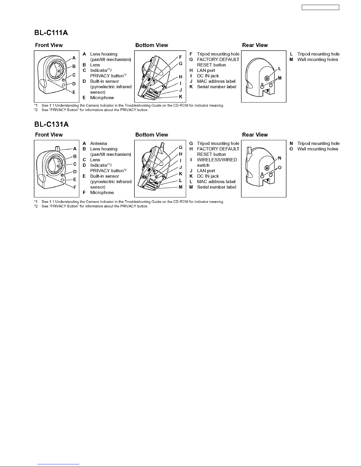
5 Location of Controls and Components
BL-C111A/BL-C131A
17
BL-C111A /BL-C131A
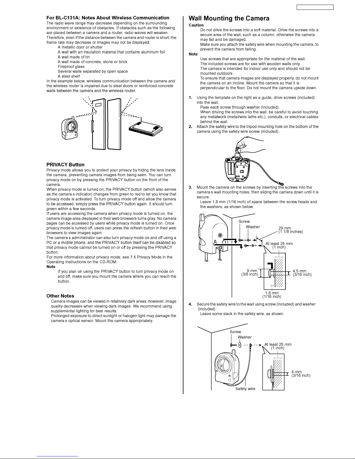
6 Installation Instructions
18
BL-C111A/BL-C131A
19

BL-C111A /BL-C131A
7 Operation Instructions
7.1. Preparation
Prepare the following before connecting the Network Camera.
• Set up software (Setup CD-ROM)
• PC to fulfill the system requirements.
• Ethernet Router or Wireless Router for LAN Connection.
• Ethernet cable (two pieces of Category 5 straight cable).
System Requirements
Your PC and network must meet the following technical specifications in order for the camera to function properly.
Item Requirement
Operating System For IPv4 Connection
Microsoft
For IPv6 Connection
Microsoft Windows Vista*1, Windows XP Service Pack 1 or later
CPU 2.0 GHz Celeron® or faster
Display 1024 x 768 resolution or higher
Protocol For IPv4 Connection
Interface 10/100 Mbps network card
Wireless Interface
(BL-C131A Only)
Web Browser Internet Explorer® 6.0 or later (not included)
Audio PC speaker or headphones (required to use the Listen feature)
Additional Software (For Viewing
Buffered MPEG-4 Images)
TCP/IP protocol (HTTP, TCP, UDP, IP, DNS, ARP, ICMP)
For IPv6 Connection
TCP/IP protocol (HTTP, TCP, UDP, IP, DNS, ICMPv6, NDP)
IEEE 802.11b/g (Embedded)
For Windows Vista
Windows Media® Player 11 or later
For Windows XP
Windows Media Player 9 or later
For Windows 2000
Windows Media Player 9
®
Windows Vista
TM*1
, Windows® XP, Windows 2000
*2
*1) As of November 2006, Windows Vista will be supported in a future firmware update.
*2) What is IPv6?
・IPv6 is short for “Internet Protocol Version 6”.
・ IPv6 was created to provide the additional IP addresses that will be needed as the Internet continues to expand.
・ IPv6 is expected to gradually replace IPv4, with the 2 coexisting for a number of years during a transition period.
・ Though most ISPs (Internet Service Providers) do not yet support IPv6, many local networks already use it. When your ISP
supports IPv6, your Panasonic Network Camera will be ready!
・ For more information, visit http://www.ipv6.org/.
Note:
Refer to the Panasonic Network Camera website at http://panasonic.co.jp/pcc/products/en/netwkcam/ for details about network environment.
20
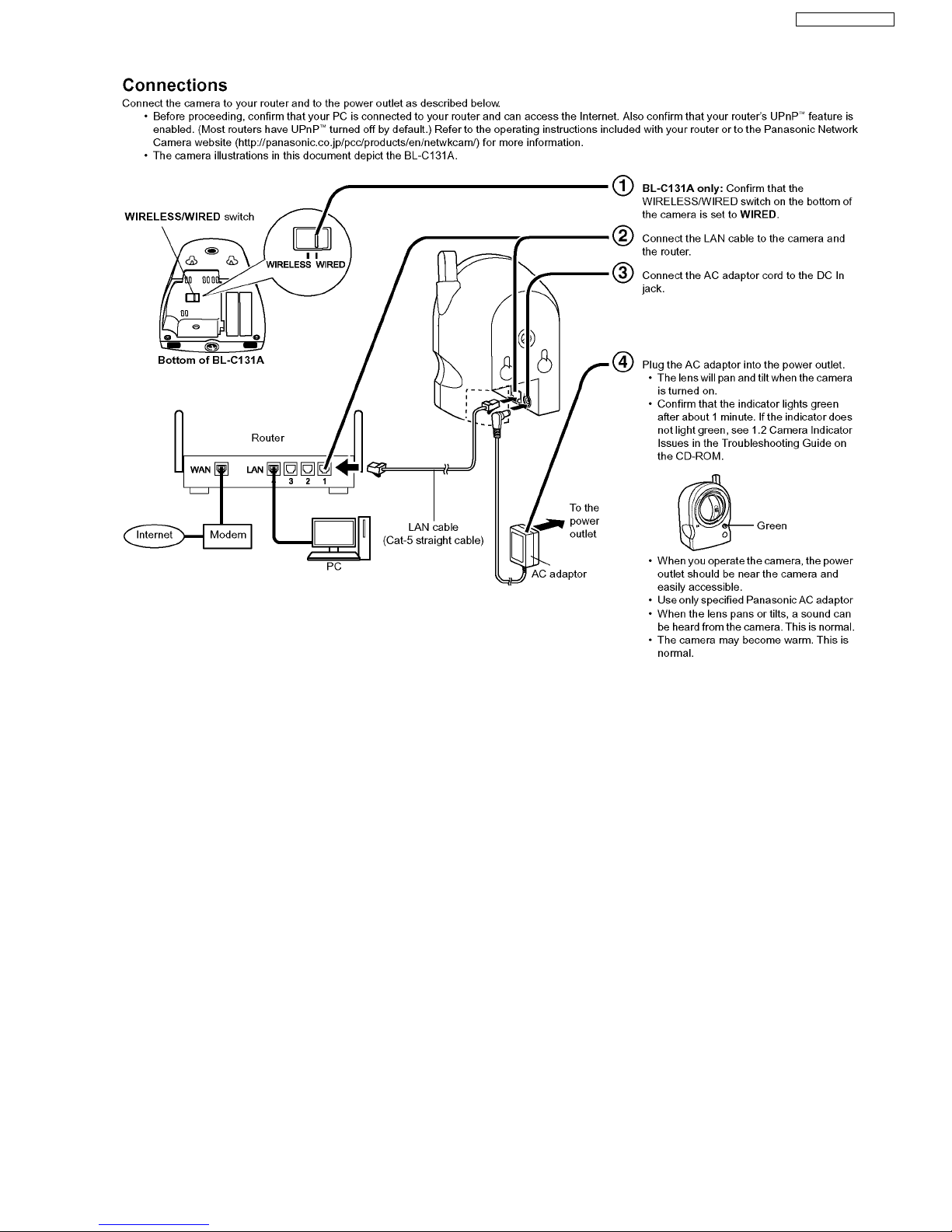
7.2. Connection
BL-C111A/BL-C131A
21
BL-C111A /BL-C131A
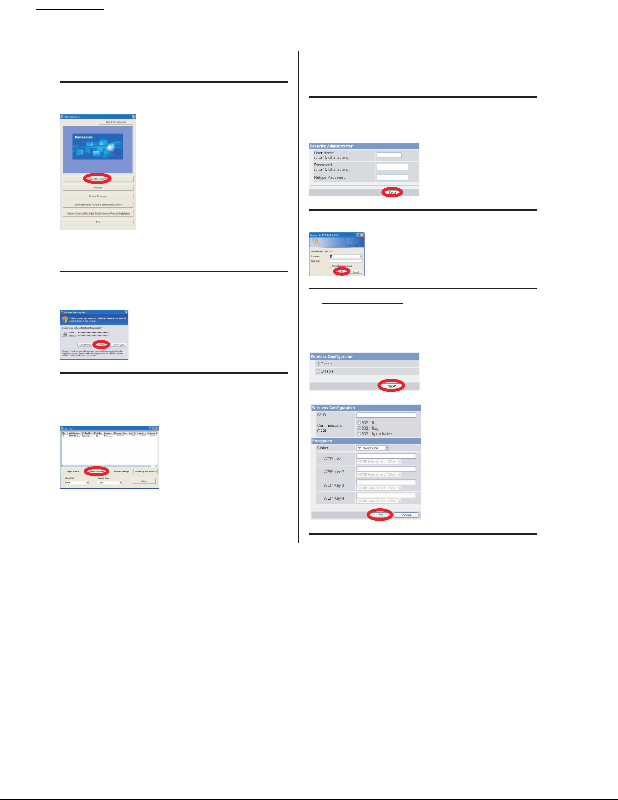
7.3. Setup Guide
1. Insert the included CD-ROM into your PC.
• The Setup Progr am starts. If the program does not start, double-click Setup.exe found
on the CD-ROM.
2. Click [Search for Cameras].
• The pro gram searches for cameras connected to your network.
• [A bout this program]: Displays the program’s version
information.
• [Search fo r Cameras]: Displays a list of cameras
connected to your network.
• [Ma nual]: Allows you to view the included
documentation. PDF versions of the printed
documentation are included on the CD-ROM; Adobe
Reader® is required to view them.
• [Update Firmware]: Allows you to use the Setup
Program to update the camera’s firmware (built-in
software).
• [Save Settings to PC/Save Settings to Camera]:
Allows you to save a backup of all camera settings on
your PC, or restore all settings in the camera using a
backup file saved on your PC.
• [Network Camera Recorder Single Camera Version
Installation]: Installs the [Network Camera Recorder
Single Camera Version] software. (See “Installing the
Network Camera Recorder Single Camera Version” on
page 2.)
• [Exit]: Closes the screen and exits the Setup Program.
®
3. When the Windows Security Alert is displayed, click
[Unblock].
• If the dialog is not displayed, continue to the next step.
• If you are using firewa ll or antivirus software on your PC, the Setup Program may not
be able to find any cameras on your network. If you cannot disable your firewall or
antivirus software, you can configure the camera by entering its MAC address (see
“Camera Diagrams” on page 2 in the Installation Guide to find your camera’s MAC
address label).
5. Enter the desired user name and password, then click
[Save].
• Do not for get the user name and password you set here, otherwise you will need to
reset the camera and configure it again.
An authentication dialog prompts you to
enter the user name and password again.
6. Enter the user name and password, then click [OK].
7. For BL-C131A Only:
Click [Next] to configure the camera’s wireless
settings, enter the wireless settings, then click [Save].
• BL-C111A users can skip this step.
• BL-C131A users can skip this step by selecting [Disable] a nd then clicking [Next].
Wireless settings will not be configured.
4. Select the camera you want to configure, and click
[Access Camera].
• To assign all network settings to the camera manually, or to assign an IP address using
the DHCP feature of your router, click [Network Settings], then select [Specify an IP
Address] or [DHCP] and enter the appropriate settings.
• If you have more than one camera, you can
distinguish cameras by model number,
printed on the front of the camera, or by
MAC address (see “Camera Diagrams” on
page 2 in the Installation Guide to find your
camera’s MAC address label).
• If more than 20 minutes have passed since
the selected camera was turned on, you
cannot configure the camera. Turn off the
camera, then turn it on again. This
restriction does not apply to cameras which
have not been configured yet or have been
reset to their factory default settings.
• Configure the camera for wireless
access by configuring the
corresponding camera settings to
match the wireless settings of your
wireless router. For more information,
refer to the operating instructions
included with your wireless router, and
to 5.2.1 Configuring the Camera for
Wireless Connection (BL-C131A Only)
in the Operating Instructions on the CDROM.
• If you have a Panasonic BB-HGW700A
Network Camera Control Unit, WEP
settings will be configured
automatically. WPA-PSK (TKIP) and
WPA2-PSK (AES) settings must be
entered manually.
22
BL-C111A/BL-C131A
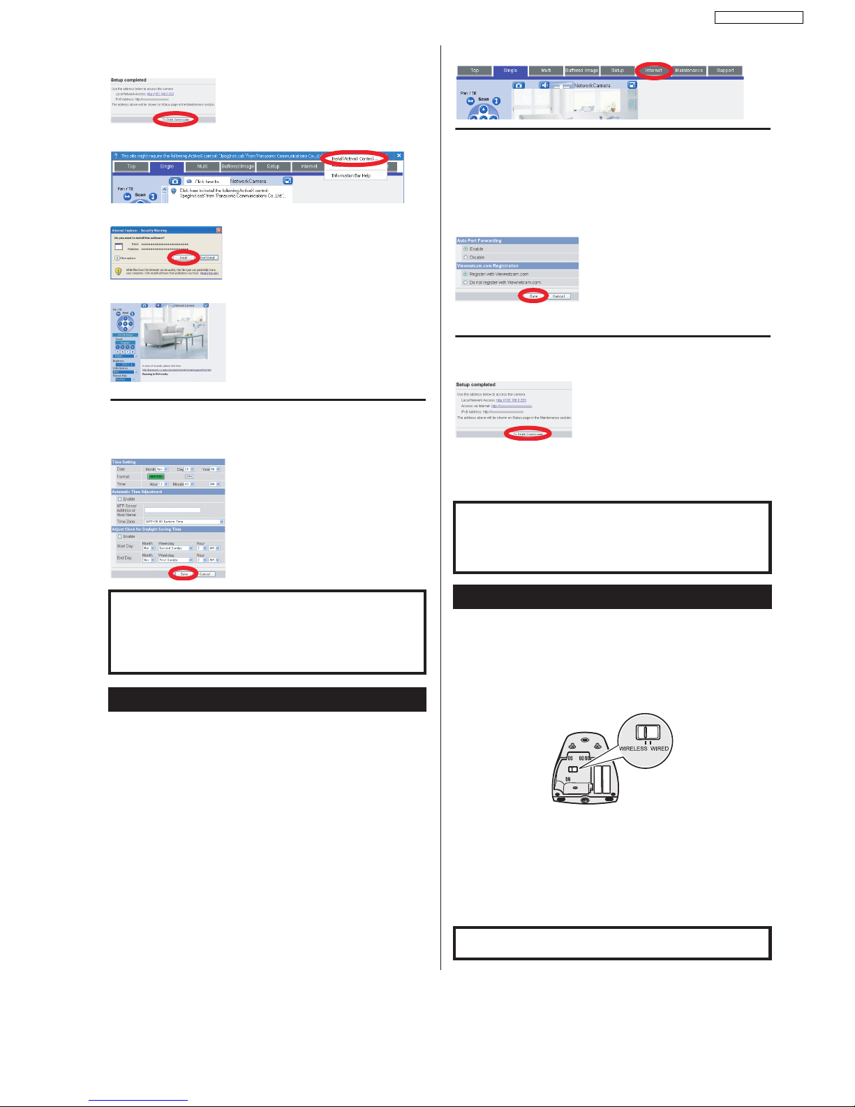
8. When [Setup completed] is displayed, click [To Single
Camera page].
• If the following ActiveX® Controls dialog is displayed, click [Install ActiveX Control...].
• When the following Security Warning is displayed, click [Install].
• The cam era image is displayed.
9. Click the [Setup] tab, click [Date and Time] on the left
side of the screen, then set the camera’s date and
time. Click [Save] when finished.
To configure the camera for access from the Internet or from a mobile
phone, continue with the following steps.
Note:
• In order to configure the camera for access over the Internet using these instructions, your
router must be UPnP
™
compatible and must have its UPnP™ feature turned on (it is turned
off by default on most routers). For more information, refer to the operating instructions
included with your router.
• To configure the camera for access over the Internet using a router that does not support
UPnP
™
, refer to Section 4 Configuring the Camera for Access from the Internet in the
Operating Instructions on the CD-ROM for general information, and refer to the operating
instructions included with your router.
• Disable the maximum idle time setting on your router if you have a PPPoE or PPTP
connection to your Internet Service Provider.
1. Click the [Internet] tab at the top of the camera screen.
2. Select [Enable] under [Auto Port Forwarding], select
[Register with Viewnetcam.com] under
[Viewnetcam.com Registration], then click [Save].
• When th e dialog about the camera’s port number changing is displayed, click [OK].
• The camera and router will begin configuring themselves via UPnP
™
.
• If you select to register with Viewnetcam.com, click [Go to Viewnetcam.com
Registration page] when it is displayed. The Viewnetcam.com website will open
automatically. Follow the on-screen instructions to register.
3. When [Setup completed] is displayed, click [To Single
Camera page].
• If you enabled [Auto Port Forwarding], the camera’s port number may have changed.
Do not forget the addresses displayed here.
• To confirm that the camera can be accessed from the Internet using a PC, use a PC
not connected to your network and access the camera using the address displayed
here.
After configuring the camera’s wireless settings, confirm that the
camera can be accessed wirelessly.
1. Disconnect the LAN cable from the camera, and
unplug the AC adaptor from the power outlet.
2. Set the WIRELESS/WIRED switch on the bottom of the
camera to WIRELESS.
3. Plug the AC adaptor in to the power outlet.
• Con firm that the indicator lights green after about 1 minute. If the indicator does not
light green, see 1.2 Camera Indicator Issues in the Troubleshooting Guide on the CDROM.
4. Start your web browser and access the camera.
• Enter camera’s IP address that was displayed during setup, then press [Enter] on the
keyboard.
• If you cannot access the camera, see 1.4 Wir eless Connection Issues (BL-C131A
Only) in the Troubleshooting Guide on the CD-ROM.
• You may need to restart your router in order to access the camera in wireless mode.
The camera’s IP address is displayed. This is the
IP address you must enter in your web browser to
access the camera. Do not forget this address.
This will install the ActiveX Controls needed to
display camera images properly. ActiveX Controls
must be installed to view MPEG-4 images,
MJPEG images, and to use audio features.
Congratulations! You have successfully set up the
camera and can now view camera images.
For more information, refer to 5.4 Setting the Date
and Time in the Operating Instructions on the CDROM.
Setup is complete. To configure the camera for access from the
Internet, see “Access from Internet Configuration”. To confirm the
camera’s wireless connection (BL-C131A only), see “Confirming
Wireless Connection (BL-C131A Only)”.
If you are finished setting up the camera, return to the Installation
Guide and follow the instructions for mounting the camera.
Access from Internet Configuration
If you are interested in accessing your camera over
the Internet, we recommend using
Viewnetcam.com. Viewnetcam.com is a Dynamic
DNS service designed for use with Panasonic
Network Cameras, and is provided free of charge.
For more information about Viewnetcam.com,
refer to the Viewnetcam.com website
(http://www.viewnetcam.com) for information
about this service.
The camera’s IP addresses for local (LAN) and
Internet access are displayed. These are the IP
addresses you must enter in your web browser to
access the camera over the LAN or from the
Internet. Do not forget these addresses.
Setup is complete. To confirm the camera’s wireless connection
(BL-C131A only), see “Confirming Wireless Connection (BLC131A Only)”.
If you are finished setting up the camera, return to the Installation
Guide and follow the instructions for mounting the camera.
Confirming Wireless Connection (BL-C131A Only)
If you are finished setting up the camera, return to the Installation
Guide and follow the instructions for mounting the camera.
23
BL-C111A /BL-C131A
8 Troubleshooting Guide
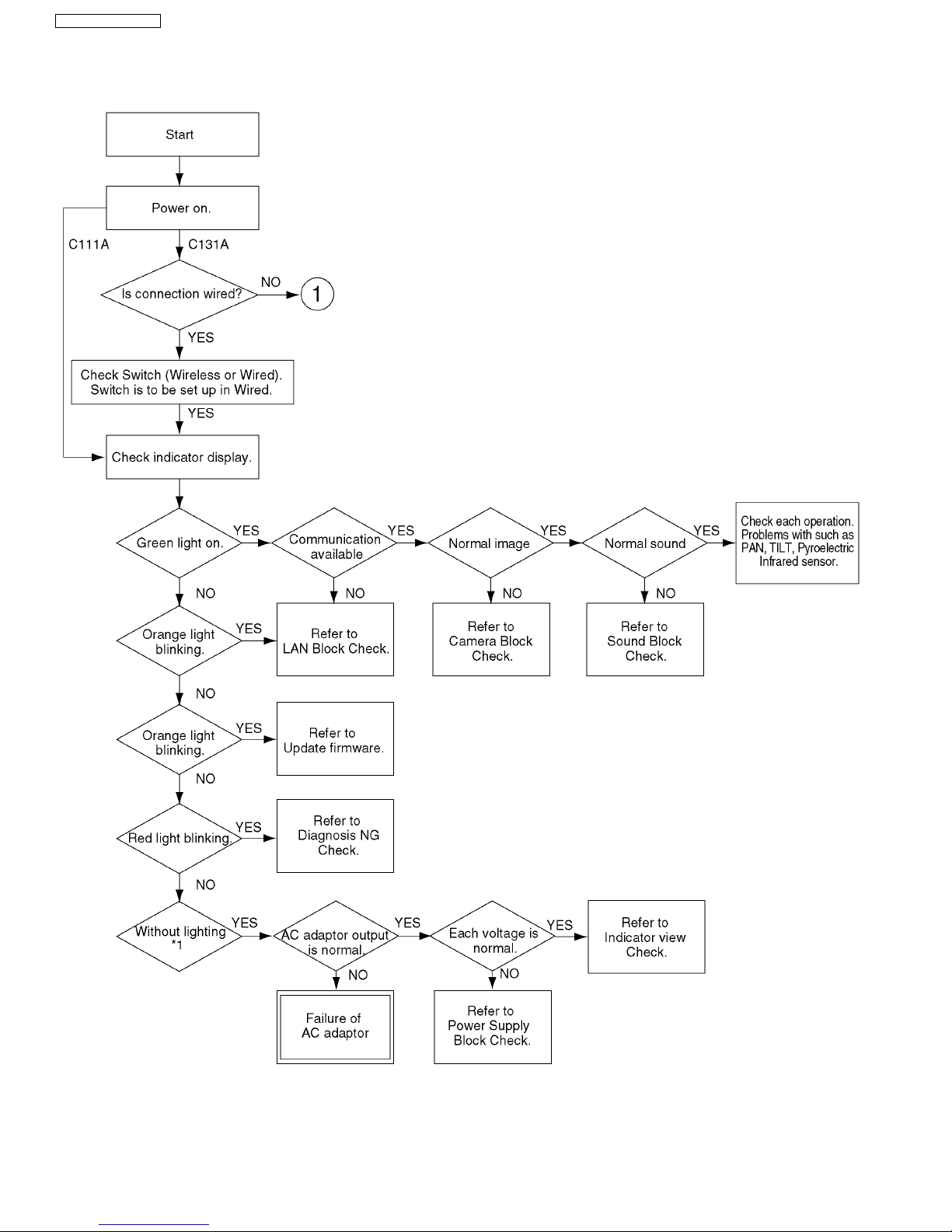
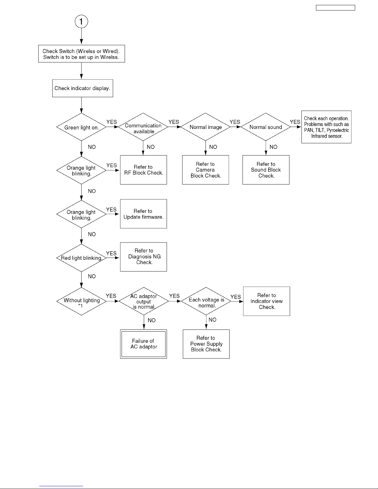
8.1. Starting Up Operation
*1 It does not turn on, when LED mode is "OFF" on web setup menu.
24
BL-C111A/BL-C131A
*1 It does not turn on, when LED mode is "OFF" on web setup menu.
25
 Loading...