

Page 1
Operating Instructions
Network Camera
Model No.
BL-C10A
Please read this manual before using and save this manual for future reference.
Panasonic Network Camera Website: http://www.panasonic.com/netcam
for customers in the USA or Puerto Rico
Page 2

Operating Instructions
Main Features
Various remote monitoring features
• Pyroelectric infrared sensor*1 detects temperature differences caused by a
human body or animals.
• Detection can let camera transfer images by E-mail or FTP*2.
• Color night view mode (auto-adjusted) enables the camera to display images
even in 1 lx illuminance*3.
Monitoring from PC or mobile phone
• The camera images can be monitored over the Internet.
• Pan/tilt operation can move the lens horizontally from -50 ° to +50 ° and
vertically from -40 ° to +10 °.
Privacy mode
• Privacy mode hides the lens into the unit to protect privacy.
• Pressing the privacy button on the front of the camera switches privacy mode
on or off with a single touch.
Privacy Monitoring Purpose
Privacy mode On Disabled Protecting privacy
Monitoring Off Enabled Remote monitoring
Easy installation using UPnP (Universal Plug and Play)
When connecting the camera with a UPnP enabled router, the camera
automatically configures its network settings.
* Some UPnP enabled routers cannot configure the camera automatically. In
this case, the router needs to be configured manually. Ask the router
manufacturer how to configure it. See Panasonic Network Camera support
website at
http://panasonic.co.jp/pcc/products/en/netwkcam/ for more information.
*1
The sensor uses pyroelectric effect. Due to the effects of environment temperature, direct
sunlight or air conditioner, it may detect the temperature differences by mistake, or the
detection range may be shortened.
*2
It may take some time to transfer images depending on the network condition.
*3
1 lx is the brightness about 2.5 m (8.2 feet) away from auxiliary fluorescent light. Color night
view mode slows down the frame rate, and images may blur when viewing a moving object or
using the pan/tilt operation.
2
Page 3

Operating Instructions
Supporting Viewnetcam.com service
Viewnetcam.com service allows you to access the camera over the Internet with
your favorite domain name (e.g. bob.viewnetcam.com) instead of a global IP
address.
* Viewnetcam.com service is the service for Panasonic Network Camera. See
Viewnetcam.com website (http://www.viewnetcam.com) for more
information.
Multi-Language Display
Top page, Single Camera and Multi-Camera page can be displayed inEnglish,
French, German, Italian, Spanish, Russian, Simplified Chinese or Japanese. If you
select English or Japanese, all pages can be changed. But if you select other
language, the Setup, Maintenance and Support pages are displayed only in
English.
[For assistance, please call: 1-800-272-7033] 3
Page 4

Operating Instructions
System Requirements for your PC
Your PC (Personal Computer) and network must meet the following technical
specifications for the camera to work properly.
Item Description
Operating
System
Microsoft
Microsoft Windows Me, Microsoft Windows XP
CPU Pentium
®
Windows® 98SE, Microsoft Windows 2000
®
III (500 MHz or greater is recommended.)
®
Protocol TCP/IP protocol (HTTP, TCP, UDP, IP, DNS, ARP, ICMP)
Interface 10/100 Mbps network card installed
Web Browser Internet Explorer 6.0 or later (Not included on the Setup CD-
ROM)
Note
See Panasonic Network Camera support website at
http://panasonic.co.jp/pcc/products/en/netwkcam/ for the latest
information about web browser.
Trademarks
• Adobe and Acrobat are either registered trademarks or trademarks of Adobe
Systems Incorporated in the United States and/or other countries.
• Ethernet is either a registered trademark or a trademark of Xerox Corporation
in the United States and/or other countries.
• Microsoft, Windows, Hotmail and ActiveX are either registered trademarks or
trademarks of Microsoft Corporation in the United States and/or other
countries.
• Pentium is a trademark or registered trademark of Intel Corporation or its
subsidiaries in the United States and other countries.
• Screen shots reprinted with permission from Microsoft Corporation.
• All other trademarks identified herein are the property of their respective
owners.
Abbreviations
•UPnPTM is the abbreviation for Universal Plug and Play.
• "Network Camera" is called "Camera" in this Operating Instructions.
4
Page 5

Operating Instructions
IMPORTANT SAFETY INSTRUCTIONS
When using this unit, basic safety precautions should always be followed to reduce
the risk of fire, electric shock, or personal injury.
1. Read and understand all instructions.
2. Keep these instructions.
3. Heed all warnings.
4. Follow all instructions.
5. After taking away the dust on the lens, wipe the lens with a cotton bud.
6. Do not install near any heat sources such as radiators, heat registers, stoves,
or other devices (including amplifiers) that produce heat.
7. Protect the AC adaptor cord from being walked on or pinched particularly at
plugs, convenience receptacles, and the point where they exit from the unit.
8. When you operate the camera, the power outlet should be near the camera
and easily accessible.
9. Do not touch the unit or the AC adaptor during lightning storms.
10. Unplug the unit when unused for long periods of time.
11. Refer all servicing to qualified service personnel. Servicing is required when
the unit has been damaged in any way, such as the AC adaptor cord or plug
is damaged, the unit does not operate normally, or has been dropped.
12. The camera is intended for indoor use only. Prolonged exposure to direct
sunlight or halogen light may damage CMOS sensor.
SAVE THESE INSTRUCTIONS
Network Camera Memo
Attach your purchase receipt here.
For your future reference
Date of purchase
Serial Number
(Found on the rear side of the main unit)
Name and address of dealer
[For assistance, please call: 1-800-272-7033] 5
MAC Address
(Found on the rear side of the main unit)
Page 6

Operating Instructions
Table of Contents
1 Camera Monitoring .......................................................8
1.1 Accessing the Camera ................................................................... 8
1.2 Viewing Single Camera page....................................................... 10
1.2.1 Bringing the Clicked Point to Center (Crick to Center) ............................ 12
1.2.2 Capturing a Still Image............................................................................. 13
1.2.3 Using Operation Bar ................................................................................ 14
1.2.4 Setting Home Position/Sensor Position/Preset Button ............................ 16
1.3 Viewing Multi-Camera page ......................................................... 20
1.4 Viewing Buffered Image page ...................................................... 22
1.4.1 Deleting Buffered Images ........................................................................ 23
1.5 Viewing Still Images on Your Mobile Phone................................. 24
2 Various Camera Features...........................................26
2.1 Using Camera Features............................................................... 26
2.2 Connecting the Camera to Your Network .................................... 28
2.3 Using UPnP (Universal Plug and Play)........................................ 32
2.4 Registering with the Viewnetcam.com service............................. 33
2.5 Setting Date and Time ................................................................. 35
2.6 Changing Camera Settings.......................................................... 37
2.7 Changing Authentication Setting and Administrator User Name and
Password ..................................................................................... 41
2.8 Logging in to the Camera............................................................. 44
2.9 Creating, Modifying or Deleting General Users ........................... 45
2.10 Changing Initial Settings on the Single Camera page or the Multi-
Camera page ............................................................................... 47
2.11 Configuring Multiple Cameras...................................................... 49
2.12 Buffering or Transferring Images by Timer .................................. 51
2.13 Buffering or Transferring Images by Sensor ................................ 58
2.14 Specifying Operation Time........................................................... 67
2.15 Changing Indicator Display .......................................................... 69
2.16 Enabling Privacy Mode ................................................................ 70
6
Page 7

Operating Instructions
3 Camera Maintenance ..................................................71
3.1 Maintenance page........................................................................ 71
3.1.1 Confirming the Status.............................................................................. 72
3.1.2 Restarting the Camera ............................................................................ 72
3.1.3 Updating the Camera Firmware .............................................................. 73
3.1.4 Creating Configuration File...................................................................... 76
3.1.5 Loading Settings from a Configuration File ............................................. 77
3.1.6 Resetting the Camera to Factory Default................................................ 78
3.2 Support page................................................................................ 79
3.2.1 Seeing Help page.................................................................................... 79
3.2.2 Seeing Product Information..................................................................... 79
3.2.3 Seeing Support Information..................................................................... 80
3.3 FACTORY DEFAULT RESET Button........................................... 81
3.4 Default Setting List....................................................................... 82
3.5 Cleaning ....................................................................................... 88
3.5.1 Cleaning the Main Unit ............................................................................ 88
3.5.2 Cleaning the Lens.................................................................................... 88
3.6 Setting an IP Address on Your PC ............................................... 89
3.7 Using Setup Program................................................................... 90
3.8 Setting Your PC............................................................................ 92
3.8.1 Setting the Proxy Server Settings on Web Browser ............................... 92
3.8.2 Setting UPnP to Display Camera Shortcut in My Network Places .......... 95
3.8.3 Setting the Internet Temporary File Setting on Web Browser.................. 95
3.9 ASCII Character Table ................................................................. 96
3.10 File Size and Number of Buffered Images ................................... 97
3.11 Specifications ............................................................................... 98
Index..................................................................................101
[For assistance, please call: 1-800-272-7033] 7
Page 8

Operating Instructions
1 Camera Monitoring
1.1 Accessing the Camera
1. Start up the web browser on your PC.
2. Enter "http://IP Address (or URL):Port Number" on the address bar, and
press [Enter] on the keyboard.
E.g. http://192.168.0.253
(or http://XXXXX.viewnetcam.com)
• When port number is 80 (default), you do not need to enter port number.
See page 30 for details about port number, and page 11 in the Installation/
Troubleshooting.
• If the Internet access to the camera is desired, the port number will be
changed in the order from 50000 to 50050. It is changed because some
ISPs block port 80.
Note
When [Prohibiting unregistered users] is set on the Security: Administrator
page, authentication window will be displayed. Enter the administrator's or the
general user's user name and password, and the Top page is displayed.
8
Page 9

Operating Instructions
3. Click the following tabs to display each page.
A B C D E F G
Select a language
to display.
A To Single Camera page (page 10) B To Multi-Camera page (page 20)
C To Buffered Image page (page 22) D To Setup page (page 26)
E To Maintenance page (page 71) F To Support page (page 79)
G To log in to the camera (page 44)
Note
When users other than an administrator are accessing the camera, [Setup]
and [Maintenance] tab will not be displayed. Additionally, When [Prohibiting
unregistered users] is set on the Security: Administrator page, [Login] tab will
not be displayed.
[For assistance, please call: 1-800-272-7033] 9
Page 10

Operating Instructions
1.2 Viewing Single Camera page
1. Access the camera (see page 8).
• The Top page is displayed.
2. Click the [Single] tab at the top of the page.
• When Security Warning window is displayed, see page 11.
Capture Image
Button
(see page 13)
Click to Center
(see page 12)
Operation Bar
(see page 14)
Refresh Interval
(see page 14)
Camera Image
3. Close the web browser.
Notes
• While viewing images under florescent lighting, the image may appear
noisy or experience flicker if the incorrect AC power setting was selected.
Select 60 Hz in the U.S. (see page 37).
• Refresh interval is [Motion] by default. You can change it on the operation
bar (see page 14).
• Refresh interval may change depending on the network condition, PC
performance and what object you view.
• When displaying video (Motion JPEG), the camera allows up to 20
simultaneous accesses. When trying more than 20 accesses, the 21st
user will see a gray screen. (Maximum 20 accesses for a Buffered Image
page too.)
• If the video (Motion JPEG) display is limited (see page 47), the video will
be changed to refreshing still images.
• To reduce the data traffic, the video can be automatically changed to
refreshing still images (see page 47).
• To display the Single Camera page directly, add it to the [Favorites] on the
web browser.
• Refresh interval may slow down depending on the network condition or
the number of accessing users.
• When viewing a dark image, Color Night View mode automatically starts.
The image will be brighter, but the refresh interval may slow down and
image quality may decrease.
10
Page 11
Operating Instructions
Security Warning window
To view a video (Motion JPEG), ActiveX® Controls must be installed. When trying
to display a video for the first time, Security Warning window will be displayed.
When using Windows 2000 or Windows XP, log in as an administrator to install it.
If you cannot install ActiveX Controls or you cannot see the video in the
Internet Explorer
• Click [Tools] [Internet Options] [Security] tab and click [Custom level] on
the web browser.
(1) Check "Prompt" in "Download signed ActiveX Controls".
(2) Check "Enable" in "Run ActiveX Controls and plug-ins".
• ActiveX Controls can be installed from the file on the Setup CD-ROM.
(1) Restart the PC.
(2) Confirm that Internet Explorer is closed.
(3) Double-click"ocx\ActiveXInst.exe" on the Setup CD-ROM.
Notes
• Video may not be displayed quickly. Wait for a while.
• If you use a proxy server, set the web browser not to access the proxy server
(see page 92).
• In some corporate network environments a firewall may be used for security
purposes. It is possible that this may prevent motion video from being
displayed. In this situation we suggest:
• Contact your network administrator.
• Try using regularly refreshed images.
[For assistance, please call: 1-800-272-7033] 11
Page 12
Operating Instructions
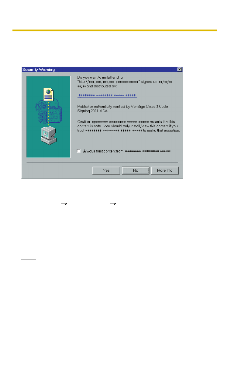
1.2.1 Bringing the Clicked Point to Center (Crick to Center)
When you click a certain point on the camera image, the point is centered on the
image.
1. Move the cursor to the desired point.
Cursor
2. Click it.
• The clicked point is centered.
• See page 15 for the pan/tilt operation.
12
Notes
• When End Display appears on the operation bar, Click to Center does not
work beyond the pan/tilt end (see page 14).
• The clicked position may slightly miss the center depending on the lens
direction.
• If a user is restricted to level 1 or 2 on the General User page (see page
45), Click to Center does not work.
Page 13

1.2.2 Capturing a Still Image
A still image can be saved on your PC.
1. Operate pan/tilt and select a resolution to display an image.
2. Click the capture image button.
Capture Image Button
• The camera image opens in another window.
3. Right-click the image, and select [Save Picture As...].
Operating Instructions
• Save as dialog box is displayed.
4. Specify the location, and click [Save].
• Camera image is saved at that location.
5. Click [Close].
[For assistance, please call: 1-800-272-7033] 13
Page 14
Operating Instructions
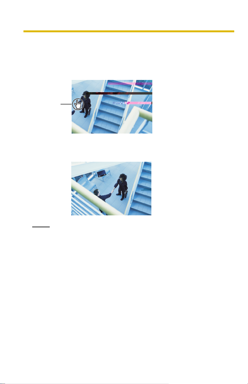
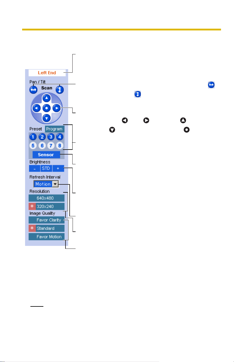
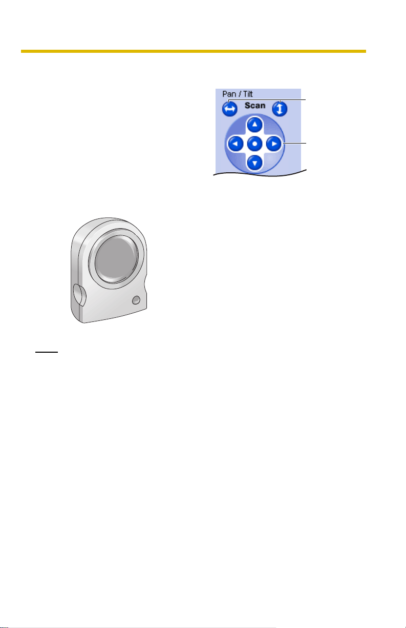
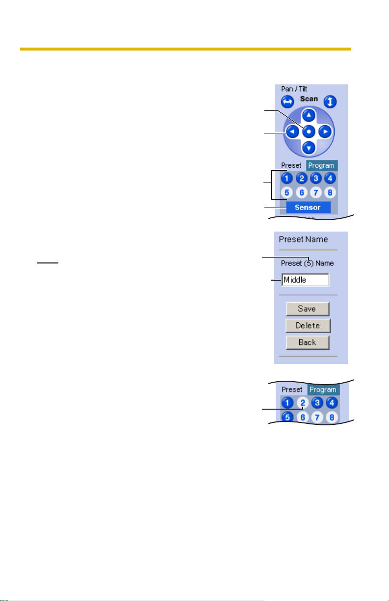
1.2.3 Using Operation Bar
End Display
and Preset
Display:
Pan/Tilt
Scan:
Pan/Tilt/
Home
Position:
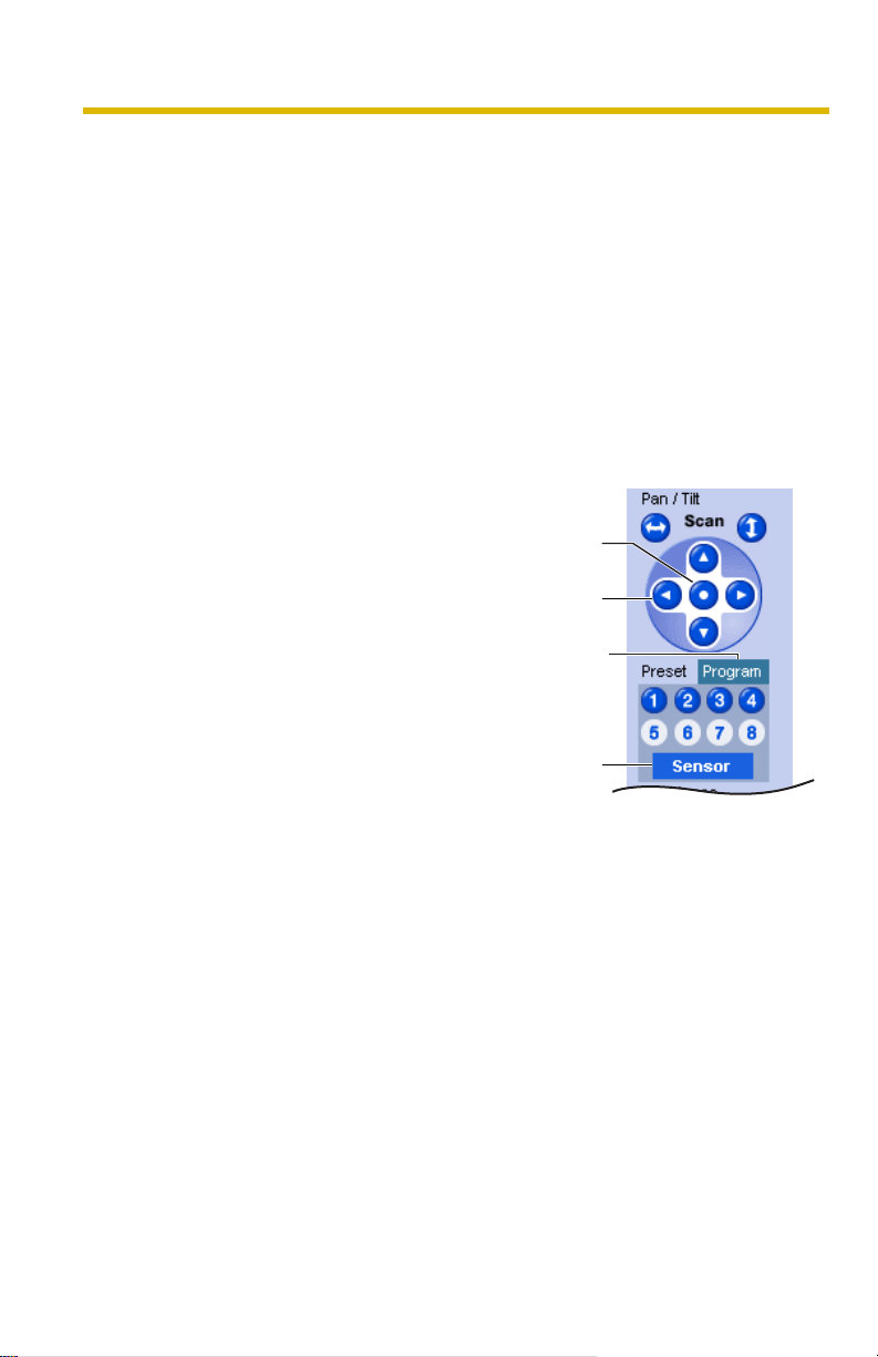
Preset
Button:
Sensor
Position:
Brightness: Changes brightness in nine steps including
Refresh
Interval:
When the pan/tilt has reached the end (Left
End, Right End, Up End and Down End), End
Display appears. When clicking a preset button,
the preset name appears.
Moves the lens throughout the horizontal ( )
or vertical ( ) range, and returns to the original
position.
Controls lens direction.
Pan ( : Left, : Right), Tilt ( : Up,
: Down) and Home Position ( : Center)
Applies the camera direction to a preset
position. You can preset 8 positions (see page
16—page 19).
When the sensor detects a temperature
difference, the camera can be set up to turn to
this position. Only an administrator can operate
it (see page 16).
[STD] (Standard). Clicking [-] or [+] changes the
image brightness.
Sets a refresh interval. (Motion—60-second
interval)
14
Resolution: Selects [640 x 480] or [320 x 240] (default)
pixels.
Image
Quality:
Selects the image quality.
• [Favor Clarity] optimizes the image for good
clarity.
• [Standard] keeps the standard quality.
(default)
• [Favor Motion] optimizes the image for
motion display.
Note
When the camera image is not displayed correctly, click [Refresh] at the tool
bar on the web browser. The image will be refreshed.
Page 15
Pan/Tilt Operation
Operating Instructions
Pan/tilt scan buttons automatically move the
lens horizontally from -50 ° to +50 ° and
vertically from -40 ° to +10 ° and return the
lens to the original position. Each pan/tilt
arrow moves the lens Up, Down, Right or
Left, and the home position button moves it to
the home position.
Pan/Tilt Range
Note
Do not apply pressure to the pan/tilt portion of the camera. Any forced
movement can damage the internal mechanism.
Pan/Tilt
Scan
Pan/Tilt
[For assistance, please call: 1-800-272-7033] 15
Page 16
Operating Instructions
1.2.4 Setting Home Position/Sensor Position/Preset Button
The home position, sensor position and 8 preset buttons can be registered. Preset
buttons (1—4) are registered 1: Upper Left, 2: Upper Right, 3: Lower Left and 4:
Lower Right. These buttons can be changed (see page 19).
• Registered buttons are shown in blue.
• Unregistered buttons are shown in white.
When clicking each button, the image switches to the home/sensor/preset position.
When restarted, the camera takes a home position. If the Lens Position When
Triggered setting is set (see page 59), the camera takes a sensor position after the
pyroelectric infrared sensor detects temperature differences.
Registering Home Position/Sensor Position
1.
Click [Program].
• [Program] switches to [Cancel].
Click [Cancel] to quit without saving
changes.
2. Pan and tilt the camera to a desired
position.
3. Click the home position button or the
sensor position button.
4. Click [Save].
• The bar switches to the operation
bar.
• Clicking [Back] takes you back to
the previous page.
Home
Position
Pan/Tilt
Program
Sensor
Position
16
Page 17
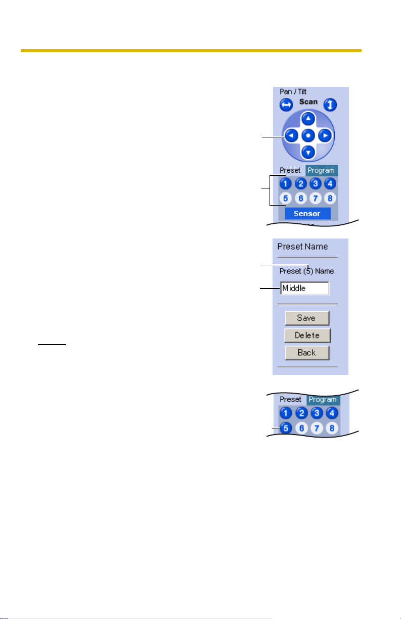
Registering a Preset Button
1.
Click [Program].
• [Program] switches to [Cancel].
Click [Cancel] to quit without saving
changes.
2. Pan and tilt the camera to a desired
position.
3. Click a preset button (1—8) to register.
E.g.:
Setting "Middle" for the preset 5.
4. Enter the preset name.
• Maximum 15 characters.
• Enter ASCII characters (see page
96) or characters in each language.
But [Space], ["], ['], [&], [<] and [>]
are not available.
5. Click [Save].
• The bar switches to the operation
bar.
• Clicking [Back] takes you back to
the previous page.
Operating Instructions
Pan/Tilt
Preset
Preset
number
Setting
a name
Notes
• When registering preset buttons,
the camera also saves brightness
and white balance settings.
• Only an administrator can register
preset buttons.
[For assistance, please call: 1-800-272-7033] 17
The button
turns blue.
Page 18
Operating Instructions
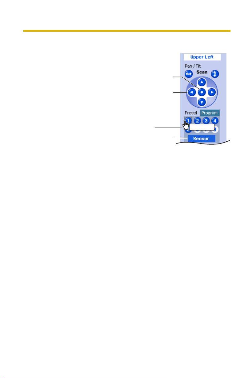
Viewing the Image
1.
Click the home position, sensor
position or registered preset button.
• The camera takes each position,
and the image is displayed.
Home
Position
Pan/Tilt
Putting the
cursor displays
the preset
name.
Sensor
Position
UpperLeft
18
Page 19
Changing or Deleting the Settings
1.
Click [Program].
• [Program] switches to [Cancel].
Click [Cancel] to quit without saving
changes.
2. Pan and tilt the camera to a desired
position.
3. Click the home position, sensor position
or a preset button (1—8).
4. Click [Save] after setting the preset
name or click [Delete].
• The bar switches to the operation
bar.
• Clicking [Back] takes you back to
the previous page.
Note
The home position or the sensor position
cannot be deleted, and these position
names cannot be changed either.
Operating Instructions
Home
Position
Pan/Tilt
Preset
Sensor
Position
Preset
number
Changing
the name
The deleted
button turns
white.
[For assistance, please call: 1-800-272-7033] 19
Page 20
Operating Instructions
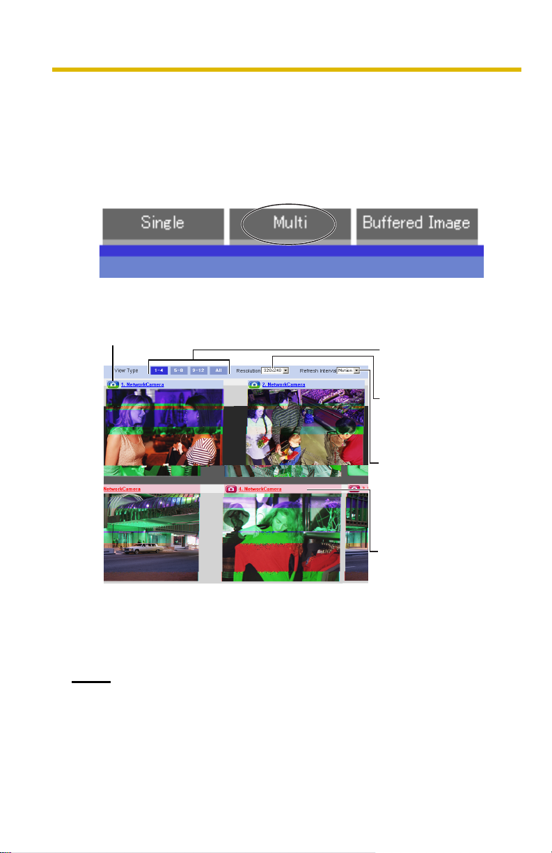
1.3 Viewing Multi-Camera page
To view multiple cameras on the Multi-Camera page, you need to configure each
camera on the Multi-Camera Setup page (see page 49).
1. Access the camera (see page 8).
• The Top page is displayed.
2. Click the [Multi] tab at the top of the page.
• Multi-Camera page can display up to 12 camera images.
Capture Image Button (see page 13)
Switches cameras to
display.
Selects [320 x 240]
(default) or [160 x 120]
pixels resolution.
Selects a refresh interval
(Motion—60-second
interval). If you select [All]
at the View Type, video
(Motion JPEG) cannot be
displayed.
When clicking the camera
name, the Single Camera
page is displayed on
another window.
20
3. Close the web browser.
Notes
• When selecting [All] at the View Type, all images are displayed in 160 x
120 pixels resolution.
• 640 x 480 pixels image cannot be displayed on the Multi-Camera page.
Page 21

Operating Instructions
• When viewing video (Motion JPEG), we recommend using an Ethernet®
switching hub instead of the repeater hub to prevent degradation in video
display.
• Due to the network congestion or the number of accesses, the refresh
interval may slow down.
• When the refresh interval is slow, restrict the bandwidth on the Network
page (see page 31). The refresh interval may be improved.
• If the video (Motion JPEG) display is limited (see page 47), the video will
be changed to refreshing still images.
• To reduce the data traffic, the video (Motion JPEG) can be automatically
changed to refreshing still images (see page 47).
• When viewing 4 cameras on the Multi-Camera page, you may need 3 to
4 Mbps bandwidth. If the bandwidth is not enough, the refresh interval may
slow down.
When the image is not displayed on the Multi-Camera page
• Confirm that the Internet IP address is specified for each camera and that each
camera is connected to the Internet. For Internet access, local IP addresses
(192.168.xxx.xxx) cannot be used.
• Confirm the settings on the Multi-Camera Setup page (see page 49).
• Confirm that the web browser is not accessing the proxy server (see page 92).
How to save a still image to your PC
On the Single Camera or Multi-Camera page
• A still image can be saved using the capture image button (see page 13).
On the Buffered Image page
• A still image can be saved on the Buffered Image page, if you are not playing
images on it. Put the cursor on the image, and right-click it. Then select [Save
Picture As...].
When setting [Do not permit unregistered users] on the Security:
Administrator page
• An authentication window is displayed in camera access. Enter the
administrator's or the general user's user name and password.
• When you view the images on the Multi-Camera page, all authentication
windows of the configured cameras are displayed. Enter the administrator's or
the general user's user name and password registered for each camera.
[For assistance, please call: 1-800-272-7033] 21
Page 22
Operating Instructions
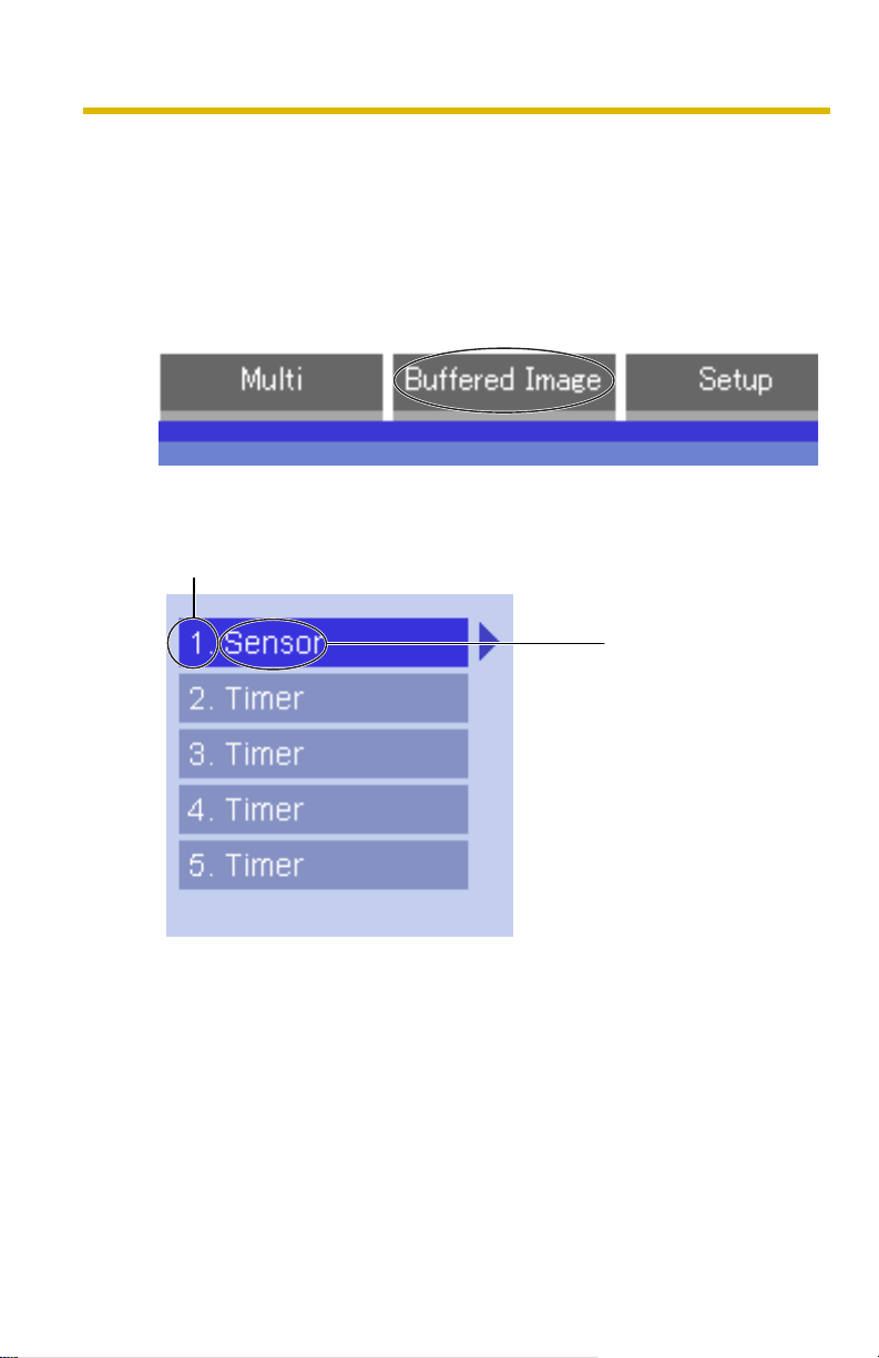
1.4 Viewing Buffered Image page
To buffer the images on the internal memory, you need to set up image transfer
settings (see page 51 or page 58). You can view buffered images on this Buffered
Image page.
1. Access the camera (see page 8).
• The Top page is displayed.
2. Click the [Buffered Image] tab at the top of the page.
3. Click the trigger number.
The trigger number is displayed (see page 51 or page 58).
The trigger is displayed
(see page 51 or page 58).
22
Page 23

Operating Instructions
4. Display images clicking buttons below.
Date and time of the day when the
images were buffered are displayed.
Date, time and frame number are
displayed.
[Play]:
The buffered images are displayed
continuously.
[<Prev] or [Next>]:
The previous or next image is
displayed.
[<10] or [10>]:
The 10th image before or after the
current image is displayed.
[<100] or [100>]:
The 100th image before or after the
current image is displayed.
Notes
• Date, Time and frame number are not displayed in play mode.
• Maximum number of buffered images change depending on resolution, image
quality and what object the camera buffers. At the 320 x 240 pixels resolution
and the standard quality, the camera buffers about 250 frames (see page 97).
(If 3 trigger settings are enabled, the internal memory capacity is divided into
3 sections. In this case, each trigger can buffer about 80 frames.)
1.4.1 Deleting Buffered Images
When restarting the camera (see page 72), all buffered images are deleted. If you
intend to delete images for each transfer condition, click [Delete Buffered Images]
on the Image Buffer/Transfer page (see page 51 or page 58).
Notes
• When you change settings (except for Enable/Disable settings) on the Image
Buffer/Transfer page, the buffered images only for that trigger will be deleted.
• The following operations also delete all buffered images.
• Turning off the camera.
• Saving the Date and Time page.
• Restarting, updating firmware or resetting the camera to factory default.
• Changing the Enable/Disable settings of Image Buffer/Transfer (see page
51 or page 58).
[For assistance, please call: 1-800-272-7033] 23
Page 24
Operating Instructions
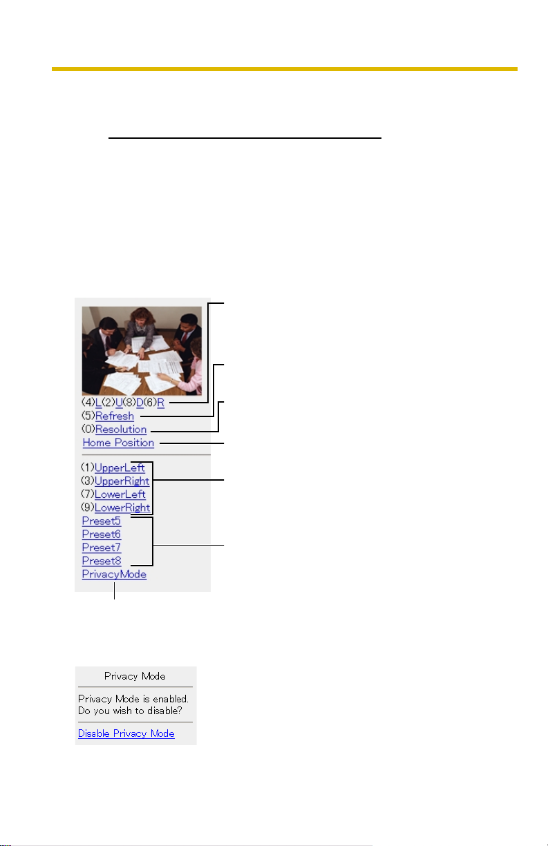
1.5 Viewing Still Images on Your Mobile Phone
You can view still images over the Internet from a compatible mobile phone.
Enter "http://IP address (or URL):Port Number/mobile" on a mobile phone and
press [OK].
• When the port number is set to 80 (default), it is not required.
E.g. http://192.168.0.253:50000/mobile
(or XXXXX.viewnetcam.com:50000/mobile)
• When an authentication window is displayed, enter the administrator's or the
general user's user name and password.
• A still image is displayed. (Video [Motion JPEG] cannot be displayed.)
Pressing 2, 4, 6 or 8 on the mobile phones allows
you to pan or tilt the camera in four directions:
Left, Up, Down or Right.
Pressing 5 will refresh the image.
160 x 120 resolution is displayed at the first
access. Pressing 0 switches the resolution to 320
x 240.
Executing [Home Position] moves the lens to the
home position.
Pressing 1, 3, 7 or 9 on the keypad allows you to
use the first four registered preset buttons.
24
Registered presets 5—8 are available by
activating the link on the mobile phone page.
If you execute [Pr ivac y Mo de] her e, th e cam era s wit c hes to pr ivac y mode. To
disable it, access the camera again and execute [Disable Privacy Mode] (see
page 70).
Page 25
Operating Instructions
Notes
• If the image is not displayed properly, try the following 2 URLs.
1. http:// IP address(or URL):Port Number/mobileh
(or XXXXX.viewnetcam.com:50000/mobileh)
2. http:// IP address(or URL):Port Number/mobilex
(or XXXXX.viewnetcam.com:50000/mobilex)
• Only an administrator can control privacy mode.
• In privacy mode, sensor and timer image buffer/transfer features also are
stopped.
• When executing [Privacy Mode] while setting [Allowing unregistered users] on
the Security: Administrator page (see page 41), an authentication window is
displayed. Log in to the camera as an administrator.
• If the users are restricted to level 1 or 2 on the General User page (see page
45), the users do not see some kinds of buttons.
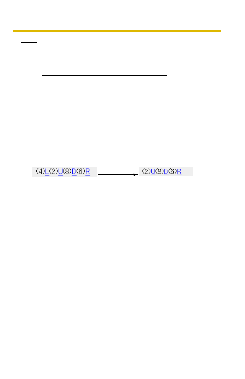
• When pan/tilt reaches the end, the keypad number and character disappear.
E.g.: The pan reaches the left end.
"(4)L" disappears.
• Some mobile phones are not compatible with Panasonic Network Cameras.
Some phones may allow viewing only on port 80, and some may not support
password authentication. See the Panasonic Network Camera support
website at http://panasonic.co.jp/pcc/products/en/netwkcam/ for a mobile
phone model list, and the compatibility level which has been verified with the
Panasonic Network Camera.
• Some mobile phones display images not at the specified resolution but at a
decreased size.
for HTML.
for XHTML.
Stopping E-mail Transfer by the Mobile Phone Operation
Executing privacy mode on a mobile phone operation can stop E-mail transfer.
1. Access the camera from a mobile phone (see page 24) and log in to the
camera as an administrator.
2. Execute [Privacy Mode] (see page 24).
• The camera switches to privacy mode and stops E-mail transfer (Image
Buffer/Transfer).
[For assistance, please call: 1-800-272-7033] 25
Page 26
Operating Instructions
2 Various Camera Features
2.1 Using Camera Features
1. Access the camera (see page 8).
Notes
• When [Allowing unregistered users] is set on the Security: Administrator
page, click [login] button and log in as an administrator.
• When users other than an administrator are accessing the camera, the
[Setup] and [Maintenance] tabs are not displayed.
• The Top page is displayed.
2. Click [Setup] tab at the top of the page.
(1)
(2)
(3)
(4)
(5)
(6)
(7)
26
(8)
(9)
(10)
(11)
(12)
(13)
Page 27

Operating Instructions
Basic
(1) Network Configures the network settings such as connection mode
to connect the camera to the network (see page 28).
(2) UPnP Enables automatic port forwarding or shortcut to the
camera (see page 32).
(3) Viewnetcam.
Registers with the Viewnetcam.com service (see page 33).
com
(4) Date and Time Sets the date and time, automatic time adjustment and
adjust clock for daylight saving time settings (see page 35).
(5) Camera Sets camera name, white balance, AC power source
frequency and pan/tilt range (see page 37).
Account
*1
(6) Administrator
Sets authentication setting and administrator security (user
name and password) (see page 41).
*1
(7) General User
Sets general user security (user name and password) and
general user's feature restriction (see page 45).
Advanced
(8) Image Display Sets resolution, image quality and refresh interval of Single
Camera and Multi-Camera page, limit continuous motion
*1
JPEG
, and language (see page 47).
*1
(9) Multi-Camera
Sets the camera IP address or host name, camera name on
the Multi-Camera page (maximum 12 cameras) (see page
49).
(10) Buffer/Transfer Sets image buffer or transfer by timer or sensor. (see page
51 or page 58).
(11) Operation Time Sets time period to display camera images (see page 67).
(12) Indicator
Sets indicator display (see page 69).
Control
(13) Privacy Mode Enables privacy mode (see page 70).
*1
If you change [Administrator], [General User], [Limit Continuous Motion JPEG] or [MultiCamera Setup page] settings, changes will not be applied to the video (Motion JPEG)
viewers. Restart the camera to make changes applied to all video viewers.
[For assistance, please call: 1-800-272-7033] 27
Page 28
Operating Instructions
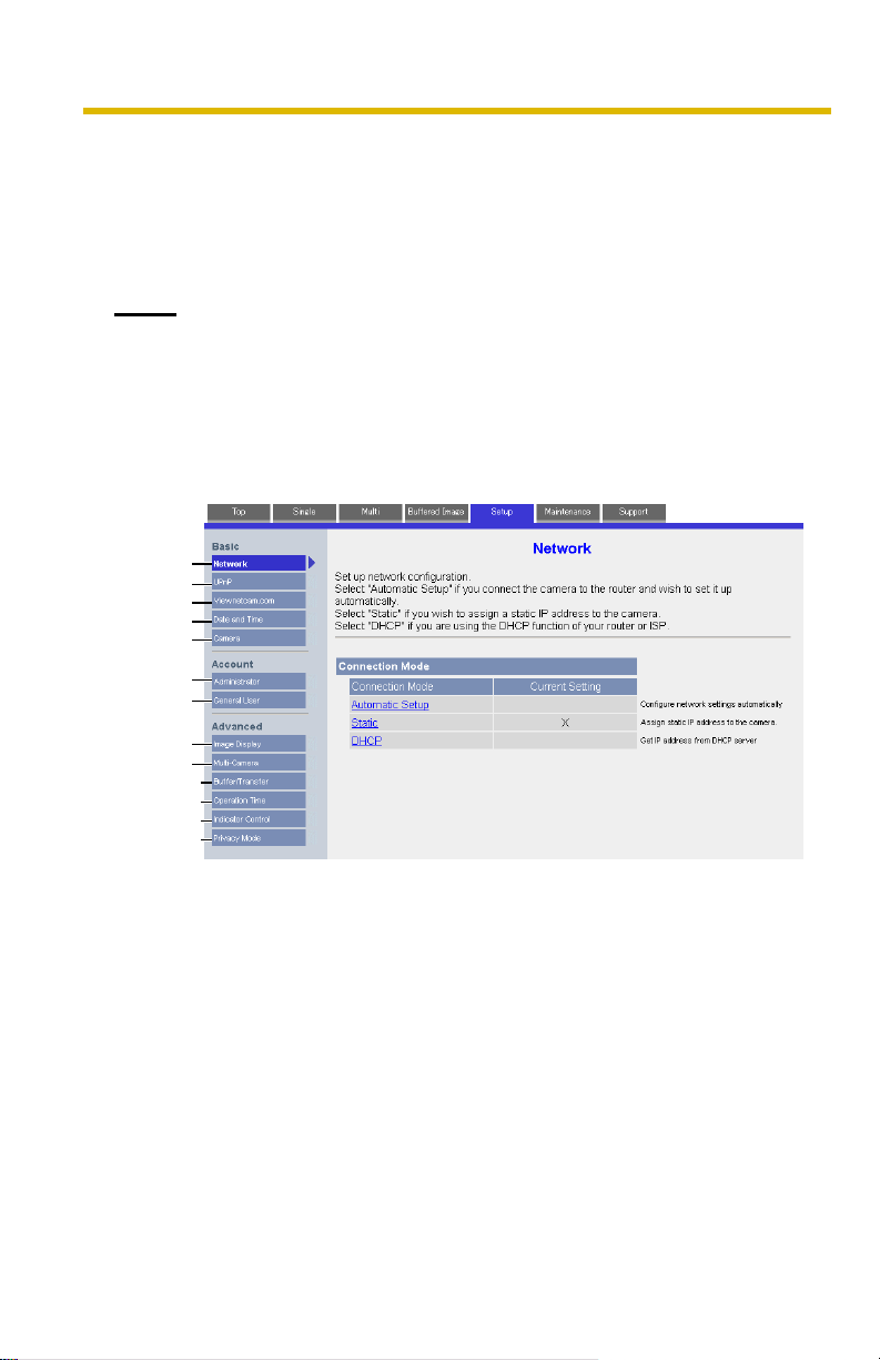
2.2 Connecting the Camera to Your Network
The Network page offers three options to configure the camera.
• [Automatic Setup] automatically assigns an unused IP address to the camera,
and uses UPnP (Universal Plug and Play) to configure your router.
• [Static] allows the user to use a specific IP address.
• [DHCP] is offered for ISPs who require this option.
1. Click [Network] on the Setup page.
2. Select a connection mode.
Normally sets Automatic Setup.
Uses a static IP address.
Uses ISP DHCP server function.
• Each page is displayed (see page 28—page 29).
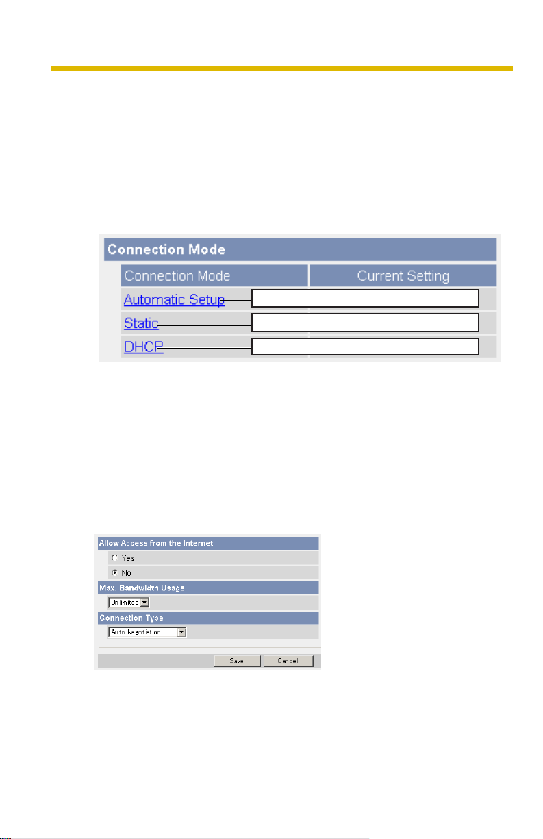
3. Enter each parameter in the proper data field.
Automatic Setup
The camera automatically obtains the network settings (subnet mask, default
gateway and DNS server address) utilizing a DHCP feature on the router. The
camera also automatically searches the unused IP address on your network.
If you select [Yes] at the Allow Access from the Internet, the camera
automatically enables port forwarding by using UPnP. In this case, the camera
automatically searches the unused port number on your network in the order
from 50000 to 50050.
28
• Clicking [Cancel] takes you back to the previous page without saving
changes.
Page 29
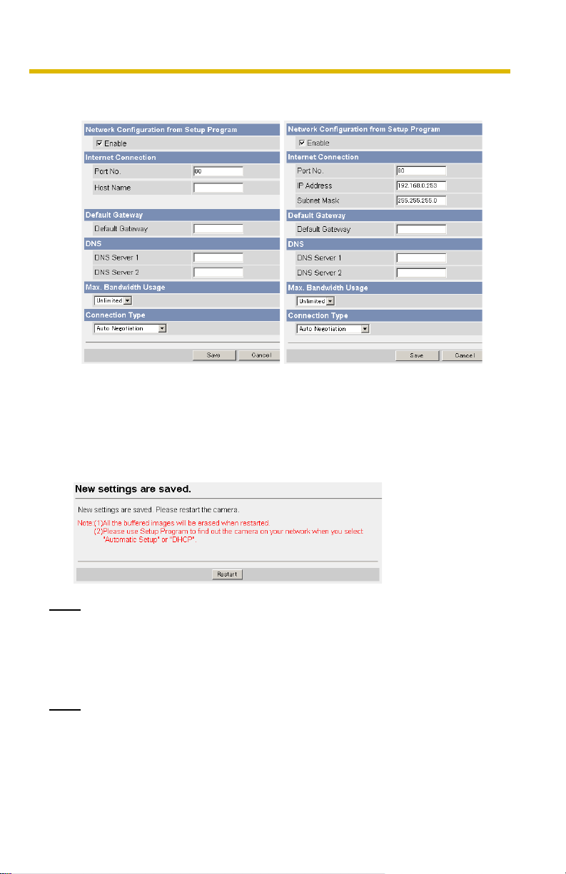
DHCP Setup Static Setup
• Clicking [Cancel] takes you back to the previous page without
saving changes.
4. Click [Save] when finished.
• New settings are saved.
• When finished, the following page is displayed.
Operating Instructions
Note
The current network settings are shown on the Status page in the Maintenance
section (see page 72).
5. Click [Restart].
• The camera restarts, and the Top page is displayed.
Note
When you do not know the camera IP address while setting [Automatic Setup]
or [DHCP Setup], you can search the camera IP address by using the Setup
Program (see page 90).
[For assistance, please call: 1-800-272-7033] 29
Page 30

Operating Instructions
Setting Description
Allow Access from
the Internet
(Automatic Setup
Only)
Network
Configuration from
Setup Program
(Static/DHCP Only)
Port Number
(Static/DHCP Only)
• IP address
• Subnet Mask
(Static Only)
• Allow Access from the Internet setting automatically
configures the router's Port Forwarding setting (some
routers call it "Address Translation", "Static IP
Masquerade", "Virtual Server" or "Port Mapping"). To
enable Internet access to the camera, check [Yes]. In this
case, the camera automatically searches the unused port
number on your network in the order from 50000 to 50050.
To disable Internet access to the camera, check [No].
• If you prohibit the Setup Program from changing the
network settings, clear the check box.
• You can set the camera port number (80 by default). When
you use multiple cameras with a router on your network,
each camera must be assigned its own port number (see
page 11 "1.5 Connecting the Camera to a Router Not
Supporting UPnP" in the Installation/Troubleshooting).
• Do not set the following port numbers.
E.g., FTP: 20 and 21, Telnet: 23, SMTP: 25, DNS: 53,
POP3: 110, HTTPS:443, ICQ: 4000 and IRC: 6661—6667.
• Enter only the number (1—65535).
• Some ISPs do not allow you to use port 80. Ask your ISP
or network administrator about the accessible port number
over the Internet.
• If your ISP or network administrator specifies the IP
address and subnet mask, enter them in each data field.
• If you use the camera on the LAN, set the IP address in the
same class as your PC (see page 89).
• Set 4 digits (0—255) and 3 periods such as
"192.168.0.253". But "0.0.0.0" and "255.255.255.255" are
not available.
Host Name
(DHCP Only)
30
• If your ISP uses the DHCP function which automatically
assigns the IP address to the camera, enter the ISPassigned host name. (Host name may be used as an
authentication.)
• Enter ASCII characters for the host name (see page 96).
But [Space], ["], ['], [&], [<] and [>] are not available.
Page 31

Setting Description
Default Gateway
(Static/DHCP Only)
*1
• If you have the assigned Default Gateway address by your
ISP or network administrator, enter it in this data field.
• Set 4 digits (0—255) and 3 periods such as
"192.168.0.253". But "0.0.0.0" and "255.255.255.255" are
not available.
Operating Instructions
DNS Server
Address
*1
(Static/DHCP Only)
• DNS server address is required in the following conditions.
• Transferring camera images by E-mail or FTP
• Setting cameras by their host names on the Multi-
Camera Setup page
• Using the Viewnetcam.com service
• If you have the assigned DNS server addresses by your
ISP or network administrator, enter them in this data field.
They usually have two addresses.
• Set 4 digits (0—255) and 3 periods such as
"192.168.0.253". But "0.0.0.0" and "255.255.255.255" are
not available.
Max. Bandwidth
Usage
• The bandwidth can be restricted.
• Select the maximum bandwidth usage from [Unlimited] to
[0.1 Mbps].
Note
Set the maximum bandwidth usage seeing the following
file sizes. These are examples for a JPEG file with a
standard image quality. File sizes may change depending
on the image quality or how bright the object is.
160 x 120 pixels: About 3 KB (24 Kbit)
320 x 240 pixels: About 10 KB (80 Kbit)
640 x 480 pixels: About 18 KB (144 Kbit)
Connection Type • Select [Auto Negotiation] normally. If you cannot access
the camera, see page 19 "The Top page is not displayed."
in the Installation/Troubleshooting.
*1
If you automatically obtain the IP address from the DHCP server, you do not need to set it.
[For assistance, please call: 1-800-272-7033] 31
Page 32

Operating Instructions
2.3 Using UPnP (Universal Plug and Play)
UPnP can automatically configure your router to be accessed from the Internet. In
order to use this feature, your router needs to support this feature and it must be
enabled. Most router manufacturers disable this feature as the default setting. See
http://panasonic.co.jp/pcc/products/en/netwkcam/technic/rtr_setup for
details and see your router manual for how to enable UPnP. After the UPnP is
enabled on the router, set [Enable] for auto port forwarding.
1. Click [UPnP] on the Setup page.
2. Set up UPnP.
Setting Description
32
Auto Port
Forwarding
• If the network setting is [Static] or [DHCP], enabling auto
port forwarding allows you to access the camera from the
Internet.
Note
If the network setting is [Automatic Setup], enable [Allow
Access from the Internet] on the Network page (see page
30).
Display Shortcut
Icon in My
Network Places
• Enabling it displays a shortcut to the camera in the My
Network Places folder.
Note
If you use Windows XP or Windows Me, this feature is
available. Enable UPnP Windows component before using
this feature (see page 95).
3. Click [Save] when finished.
• New settings are saved.
• When finished, "Success!" is displayed.
4. Click [Go to UPnP page].
• The UPnP page is displayed.
Page 33

Operating Instructions
2.4 Registering with the Viewnetcam.com service
Viewnetcam.com is a free service (dynamic DNS service) that allows you to assign
an easy to remember name to the camera, similar to your favorite web site.
Viewnetcam.com also allows you to easily access the camera, even when your ISP
changes the IP address. Panasonic Communications recommends you to register
with it for the Internet access to the camera. See http://www.viewnetcam.com for
details about the Viewnetcam.com service.
1. Click [Viewnetcam.com] on the Setup page.
2. Check [Enable].
• Clicking [Cancel] cancels your settings without saving changes.
Setting Description
Enable • Check [Enable] to register with the Viewnetcam.com
service. If you clear the box, the Viewnetcam.com service
stops.
Personal
(Camera) URL
Your Account
Link
• The camera's personal URL will be displayed after you
register with the Viewnetcam.com service.
• The URL is displayed to register with the Viewnetcam.com
service. Clicking [Your Account Link] item name displays
the Viewnetcam.com registration website.
3. Click [Save] when finished.
• New settings are saved.
• When finished, "Success!" is displayed.
4. Click [Go to Viewnetcam.com page].
• The Viewnetcam.com page is displayed.
5. Click [Your Account Link].
• The Viewnetcam.com registration website is displayed.
[For assistance, please call: 1-800-272-7033] 33
Page 34

Operating Instructions
Notes
• When the Viewnetcam.com registration website is not displayed, confirm
that the URL is displayed in the right column of the Your Account Link. If
the URL is not displayed, follow the procedures below.
1. Wait for a while, and click [Refresh] on the web browser.
2. Confirm that your network (your PC and camera) is connected to the
Internet.
• Personal (Camera) URL is available after you registered with the
Viewnetcam.com service.
• If port forwarding is not enabled or your network is not connected to the
Internet, the Viewnetcam.com service is not available.
6. Register with the Viewnetcam.com service following the website.
• The Viewnetcam.com page is displayed.
7. Access the camera with a registered URL from the Internet (see page 8).
• When the Top page is displayed, the Viewnetcam.com registration is
complete.
Notes
• It may take a maximum of 30 minutes for the registered URL to work.
• If "Expired" is displayed at the Personal (Camera) URL on the
Viewnetcam.com page or at the Camera URL in the DDNS on the Status
page, restart the camera. After that, confirm that your registered URL is
displayed on their pages.
34
Page 35

Operating Instructions
2.5 Setting Date and Time
The Date and Time page allows you to set date and time. Date and time are used
for image buffer/transfer, operation time and time stamps on the buffered image.
Note
Saving the date and time settings deletes all buffered images.
1. Click [Date and Time] on the Setup page.
2. Set each parameter.
• Clicking [Cancel] cancels your settings without saving changes.
[For assistance, please call: 1-800-272-7033] 35
Page 36

Operating Instructions
Setting Description
Time Setting • Select date and format (AM/PM or 24 H). These settings
are used for image buffer/transfer, operation time and time
stamps on the buffered image. But E-mail subject and file
name by E-mail or FTP transfer uses only 24 h format.
Automatic Time
Adjustment
Adjust Clock for
Daylight Saving
Time
• NTP (Network Time Protocol) server synchronizes the
camera's internal clock. It adjusts automatically every day.
Check the box to enable it.
• Set the NTP server IP address, set 4 digits (0—255) and 3
periods such as "192.168.0.253". But "0.0.0.0" and
"255.255.255.255" are not available. Or set a host name
(1—255 characters).
• Select your time zone.
• During the daylight saving time, the internal clock is turned
forward an hour. The clock will shift one hour forward at the
set time on the Start Day, and move back one hour at the
set time on the End Day. Check the box to enable it.
Note
An "s" is put between date and time of time stamp when
enabling this feature. The time stamp will be attached to
the transferred images by the Image Transfer feature.
3. Click [Save] when finished.
• New settings are saved.
• When finished, "Success!" is displayed.
4. Click [Go to Date and Time page].
• The Date and Time page is displayed.
Note
Date and time settings are subject to change due to the temperature. Date and
time settings may lose about 1 minute per month in 25 °C (77 °F). They may
lose more minutes in colder or hotter places. Confirm the date and time
settings once a month.
36
Page 37

Operating Instructions
2.6 Changing Camera Settings
The Camera page allows you to set the camera name, white balance, AC power
source frequency and pan/tilt range.
1. Click [Camera] on the Setup page.
2. Set each parameter.
• Clicking [Cancel] cancels your settings without saving changes.
[For assistance, please call: 1-800-272-7033] 37
Page 38

Operating Instructions
Setting Description
Camera Name • The camera name is displayed on the Single Camera
page.
• Enter ASCII characters (see page 96) or characters in
each language (1—15 characters for a 1-byte character
and 1—7 characters for a 2-byte character). But [Space],
["], ['], [&], [<], and [>] are not available.
White Balance Select from the following options.
• Auto (default) — Automatic adjustment
• Fixed Indoor — Electric bulb (2800 K)
AC Power
Source
Frequency
Pan Range
• Fixed Fluorescent
— White (3600 K)
(White)
• Fixed Fluorescent
— Daylight (4000 K)
(Daylight)
• Fixed Outdoor — Solar light (6000 K)
• Hold — Setting [Hold] keeps the current
white balance.
Note
White balance is also saved in the home position, sensor
position and preset buttons.
• In some cases, the image may have noise due to
fluorescent light. Select 60 Hz for the United States.
•50 Hz
• 60 Hz (default)
*1
Select from the following options.
• Minimum — Current settings, -50—+50
• Home Position
• Maximum — Current settings, -50—+50
• The values must be selected as minimum home
position maximum.
*2
— Current settings, -50—+50
38
Page 39

Operating Instructions
Setting Description
Tilt Range
*1
Select from the following options.
• Minimum — Current settings, -40—+10
*2
• Home Position
— Current settings, -40—+10
• Maximum — Current settings, -40—+10
• The values must be selected as minimum home
position maximum.
*1
See page 40 for details about pan/tilt range settings.
*2
These home position settings are displayed as you set on page 16.
3. Click [Save] when finished.
• New settings are saved. If the home position is changed, the camera turns
to the home position.
• When finished, "Success!" is displayed.
4. Click [Go to Camera page].
• The Camera page is displayed.
[For assistance, please call: 1-800-272-7033] 39
Page 40

Operating Instructions
Specifying Pan/Tilt Range
1.
Access the camera (see page 8), and click [Single] at the top of the Top page.
2. Open another web browser, and display the Camera page (see page 37).
3. Align the Single Camera page and the Camera page side to side.
4. Set the pan/tilt range.
• Selecting [Current Settings] displays the current angle of the camera.
Select each value while adjusting the pan/tilt on the Single Camera page.
Note
The values must be selected as minimum home position maximum.
40
Max.: +10 ˚
Max.: +50 ˚
Min.: -40 ˚
Min.: -50 ˚
5. Click [Save] on the Camera page.
• New settings are saved. The camera turns to the home position.
Page 41

Operating Instructions
2.7 Changing Authentication Setting and Administrator User Name and Password
The Security: Administrator page allows you to change authentication,
administrator user name and password. The authentication window is displayed,
and allows the registered users to access the camera.
Notes
• If you access the camera for the first time, the window to set administrator user
name and password is displayed. Make a note of the user name and password
so that you will not forget them.
• The user name and password should be secured at your own responsibility.
Pay attention to the following points.
• Set the user name and password as many characters as possible.
• Change the password regularly.
1. Click [Administrator] on the Setup page.
2. Set each parameter.
• Clicking [Cancel] cancels your settings without saving changes.
[For assistance, please call: 1-800-272-7033] 41
Page 42

Operating Instructions
Setting Description
General
Authentication
User Name/
Password
Authentication has 2 phases.
• If you set [Permit access from guest users], the camera
does not display the authentication window in camera
access. All guest users can view the image without user
name and password.
Note
If you set [Permit access from guest users], [Login] is
displayed at the top of the page. After you log in as an
administrator (see page 44), you can access the Setup
page and the Maintenance page.
• If you set [Do not permit access from guest users], the
camera displays authentication window in camera access.
Users must enter the user name and password.
• User Name (6 to 15 characters): Enter the user name.
• Password (6 to 15 characters): Enter the password.
Note
The password must be different from the user name.
• Retype Password: Reenter the password.
• Enter ASCII characters (see page 96). But [Space], ["], ['],
[&], [<], [>] and [:] are not available.
42
Note
When users other than an administrator are accessing the camera, [Setup]
and [Maintenance] tab will not be displayed.
3. Click [Save] when finished.
• New settings are saved.
• When finished, "Success!" is displayed.
Page 43

Operating Instructions
4. Click [Go to Security: Administrator page].
• The Security: Administrator page is displayed.
Notes
• When the user name and password have been changed, the camera
displays an authentication window. Enter the user name and password,
and click [OK].
Administrator/General Users/Guest Users
The camera has 3 user levels (administrator, general users and guest users).
Items Administrator General Users Guest Users
User Name and
Password
Number of Users 1 50 —
Accessible Pages All Pages Pages Except For
Access Level 1—3 All Operations Access level can
Required Required Not Required
Pages Except For
Setup and
Maintenance page
be set for each
general user (see
page 45).
Setup and
Maintenance page
Access level can
be set for guest
users (see page
45).
Note
Guest users mean unregistered users. Set [Permit access from guest users]
on the Security: Administrator page (see page 41).
[For assistance, please call: 1-800-272-7033] 43
Page 44

Operating Instructions
2.8 Logging in to the Camera
If you set [Permit access from guest users] on the Security: Administrator page,
[Login] is displayed at the top of the page. After you log in as an administrator, you
can access the Setup page and the Maintenance page.
1. Click [Login] at the top of the page.
2. Check the login mode, and click [Login].
Note
The authentication window is displayed. Enter the user name and password.
44
3. Enter the user name and password, and click [OK].
• You can log in to the camera.
Page 45

Operating Instructions
2.9 Creating, Modifying or Deleting General Users
The General User page allows you to create, modify or delete general users. Up to
50 general users can be registered. The access level is set for each general user.
If you set [Permit access from guest users] on the Security: Administrator page, the
access level can be set for guest users.
1. Click [General Users] on the Setup page.
2. If you create a general user, click [Create].
• When setting [Do not permit
access from guest users]
• If you change the settings of general users or guest users, select
their name and click [Modify]. The modification page is displayed.
• If you delete a general user, select the name and click [Delete]. The
confirmation page is displayed.
• When setting [Permit access
from guest users]
3. Set each parameter.
• Settings for a general user • Settings for guest users
• Clicking [Cancel] takes you back to the previous page without
saving changes.
[For assistance, please call: 1-800-272-7033] 45
Page 46

Operating Instructions
Setting Description
User ID List • Up to 50 general users can be registered.
• The list is used to modify or delete general user settings.
User Name/
Password
• User Name (6 to 15 characters): Enter the user name.
• Password (6 to 15 characters): Enter the password.
Note
The password must be different from the user name.
• Retype Password: Reenter the password.
• Enter ASCII characters (see page 96). But [Space], ["], ['],
[&], [<], [>] and [:] are not available.
Access Level Access level is set for each general user. Each level offers
different operations.
• Level 1 users view only image.
• Level 2 users view the image and operate only preset
buttons.
• Level 3 users view the image and control all operations.
4. Click [Save] when finished.
• New settings are saved.
• When finished, "Success!" is displayed.
5. Click [Go to General User page].
46
Page 47

Operating Instructions
2.10 Changing Initial Settings on the Single Camera page or the Multi-Camera page
The Image Display page allows you to change initial settings (display settings
when a user accesses the camera) of image resolution, image quality and refresh
interval. Motion JPEG display time can be set here.
1. Click [Image Display] at the top of the page.
2. Set each parameter.
• Clicking [Cancel] cancels your settings without saving changes.
[For assistance, please call: 1-800-272-7033] 47
Page 48

Operating Instructions
Setting Description
Image Resolution • Select the image resolution.
640 x 480 pixels (Only for the Single Camera page)
320 x 240 pixels (default)
160 x 120 pixels (Only for the Multi-Camera page)
Image Quality • Select the image quality.
[Favor Clarity] optimizes for good quality.
[Standard] offers standard quality.
[Favor Motion] optimizes for enhanced motion.
Refresh Interval • Select a refresh interval.
(Motion—60-second interval)
Limit Continuous
Motion JPEG
• Limit time of
Continuous
Motion JPEG
•Refresh
Interval
Language • Select the initial language from English, French,
• Set the time to change the video (Motion JPEG) to still
images. (10 seconds—Unlimited)
• Set a refresh interval after the image is changed to still
images. (3-second interval—60-second interval)
German, Italian, Spanish, Russian, Simplified Chinese
or Japanese. The selected language is displayed as
the initial language on the Top, Single Camera and
Multi-Camera page. If you select English or Japanese,
all pages can be changed. But if you select other
language, the Setup, Maintenance and Support pages
are displayed only in English.
48
3. Click [Save] when finished.
• New settings are saved.
• When finished, "Success!" is displayed.
4. Click [Go to Image Display page].
• The Image Display page is displayed.
Page 49

Operating Instructions
2.11 Configuring Multiple Cameras
The Multi-Camera Setup page allows you to configure the camera IP addresses
and camera names to view multiple images on the Multi-Camera page. These
configurations are required to use the Multi-Camera page.
1. Click [Multi-Camera] on the Setup page.
2. Click [Add].
Notes
• If you click the camera number, the modification page is displayed. The
camera setting can be modified or deleted on it.
• If you configured multiple cameras, you can change the camera number.
Select the number, and click [Move].
3. Set each parameter.
• Clicking [Cancel] cancels your settings without saving changes.
[For assistance, please call: 1-800-272-7033] 49
Page 50

Operating Instructions
Setting Description
Display • Check the box to enable the camera.
*1
or
IP Address
Host Name
• Set the IP address or the host name to enable the camera.
*2
Port No. • Set the port number (1—65535).
*3
Camera Name
• This camera name is displayed only on the Multi-Camera
page.
*1
Set 4 digits (0—255) and 3 periods such as "192.168.0.253". But "0.0.0.0" and
"255.255.255.255" are not available.
*2
Enter ASCII characters for the host name (see page 96). But [Space], ["], ['],
[#], [&], [%], [=], [+], [?], [<] and [>] are not available.
Enter 1—255 characters.
*3
Enter ASCII characters (see page 96) or characters in each language (1—15
characters for a 1-byte character and 1—7 characters for a 2-byte character).
But [Space], ["], ['], [#], [&], [%], [=], [+], [?], [<], and [>] are not available.
Notes
• Set the private IP address and port number for the camera on the same
LAN.
• If you access the camera from the Internet, set the host name (or the
global IP address) and port number.
4. Click [Save] when finished.
• New settings are saved.
• The Multi-Camera Setup page is displayed.
50
Page 51

Operating Instructions
2.12 Buffering or Transferring Images by Timer
The Image Buffer/Transfer page allows you to enable image buffer/transfer by Email or FTP.
1. Click [Buffer/Transfer] on the Setup page.
2. Click [No.] to enable buffer/transfer.
3. Check [Enable Image Buffer/Transfer], select [Timer] for trigger, and click
[Next>].
• Click [Delete Buffered Images] to delete this buffered images.
• Clicking [Cancel] takes you back to the Image Buffer/Transfer page
without saving changes.
Setting Description
Enable Image
Buffer/Transfer
Trigger • Selecting [Timer] enables the camera to buffer/transfer the
• Check the box to enable the buffer/transfer. Clear the box
to disable it.
image by timer.
• Selecting [Sensor] enables the camera to buffer/transfer
the image by sensor.
[For assistance, please call: 1-800-272-7033] 51
Page 52

Operating Instructions
4. Set the time, and click [Next>].
Note
The timer works by an internal clock. Set the date and time before using timer
buffer/transfer (see page 35).
• Clicking [<Back] takes you back to the previous page.
• Clicking [Cancel] takes you back to the Image Buffer/Transfer page
without saving changes.
Setting Description
A day of the
week
Active Time of
Trigger
• Check the box to enable the day. Clear the box to disable
it.
• Select the [Always] option when you do not specify the
time period. If you specify the time period, select the time
period option and set the time period.
5. Set the image settings, and click [Next>].
• Clicking [<Back] takes you back to the previous page.
• Clicking [Cancel] takes you back to the Image Buffer/Transfer page
without saving changes.
52
Page 53

Setting Description
Operating Instructions
Image
Resolution
Image Quality • Select the image quality.
• Select image resolution (640 x 480, 320 x 240 (default) or
160 x 120 pixels) to buffer or transfer.
[Favor Clarity] optimizes for good quality.
[Standard] offers standard quality.
[Favor Motion] optimizes for enhanced motion.
[Mobile Phone] is for a transfer to a mobile phone.
Note
640 x 480 pixels cannot be set for a transfer to a mobile
phone.
6. Set the image buffer frequencies, and click [Next>].
• Clicking [<Back] takes you back to the previous page.
• Clicking [Cancel] takes you back to the Image Buffer/Transfer page
without saving changes.
Setting Description
Image Buffer
Frequency
• Select the image buffer frequency to buffer or transfer the
image. (1 image per hour—15 images per second)
[For assistance, please call: 1-800-272-7033] 53
Page 54

Operating Instructions
7. Select the transfer method, and click [Next>].
• Clicking [<Back] takes you back to the previous page.
• Clicking [Cancel] takes you back to the Image Buffer/Transfer page
without saving changes.
Note
If you transfer image by E-mail or FTP, confirm that the default gateway and
DNS server addresses are assigned correctly (see page 28).
Setting Description
No Transfer, No
Memory
Overwrite
No Transfer,
Memory
Overwrite
FTP • The camera transfers the image to an FTP server (see
E-mail • The camera transfers the image by E-mail (see page 56).
• If the internal memory is full, the camera stops the buffer.
• If the internal memory is full, the camera deletes the old
images, and continues to buffer the image.
page 55).
54
Page 55

Operating Instructions
When you set [FTP] for Transfer Method
Select [FTP], and click [Next>]. The following page is displayed.
• Clicking [<Back] takes you back to the previous page.
• Clicking [Cancel] takes you back to the Image Buffer/Transfer page
without saving changes.
Setting Description
Server IP
Address or
Host Name
• If you set the server IP address, set 4 digits (0—255) and 3
periods such as "192.168.0.253". But "0.0.0.0" and
*1
"255.255.255.255" are not available. Or set a host name (1—
255 characters).
Port No. • Enter the number (1—65535). Usually set to 21.
*1
Login ID
Password
• If your ISP requires a login ID, set it (0—63 characters).
*1
• If your ISP requires a password, set it (0—63 characters).
Login Timing • Select the login timing to an FTP server. If you set [One Time]
during 1-minute transfer, the camera logs in to the server only
once, and can reduce the time to log in or log out.
Upload File
*1
Name
• Set the file name to save on an FTP server. Enter 1—234
characters. Entering "\" creates directories for a file. (E.g.
NetworkCamera\image.jpg)
Overwrite
Setting
• Selecting [Overwrite File] saves and overwrites the image on
the server. Selecting [Save as New File with Time Stamp]
saves the image attaching time stamps on the file name, and
the images are not overwritten.
Data
Transfer
• Select [Passive Mode] normally. If FTP does not work, select
[Active Mode] and check the operation.
Method
*1
But [Space], ["], ['], [&], [<] and [>] are not available.
[For assistance, please call: 1-800-272-7033] 55
Page 56

Operating Instructions
When you set [E-mail] for Transfer Method
Select [E-mail], and click [Next>]. The following page is displayed.
• Clicking [<Back] takes you back to the previous page.
• Clicking [Cancel] takes you back to the Image Buffer/Transfer page
without saving changes.
Note
The camera works only with an SMTP (Simple Mail Transfer Protocol) server.
It does not work with mail servers like "Hotmail
Setting Description
®
" using a web browser.
56
SMTP Server IP
Address or Host
Name
POP3 Server IP
Address or Host
Name
Login ID
Password
*1
*1
Reply E-mail
Address
*1
Destination Email Address*1
1—3
• If you set the server IP address, set 4 digits (0—255) and
3 periods such as "192.168.0.253". But "0.0.0.0" and
"255.255.255.255" are not available. Or set a host name
(1—255 characters).
• If you set the server IP address, set 4 digits (0—255) and
3 periods such as "192.168.0.253". But "0.0.0.0" and
"255.255.255.255" are not available. Or set a host name
(1—255 characters).
• If your ISP requires a login ID to log in to a POP3 server,
set it (0—63 characters).
• If your ISP requires a password to log in to a POP3 server,
set it (0—63 characters).
• Set the sender's E-mail address. We recommend you to
set the administrator's E-mail address.
• Set the destination E-mail address (up to 3).
Page 57

Operating Instructions
Setting Description
Subject • Enter a subject with ASCII characters (see page 96) or
characters in each language (0—44 characters for a 1byte character and 0—22 characters for a 2-byte
character). But ["] is not available.
Text • Enter text with ASCII characters (see page 96) or
characters in each language (0—63 characters for a 1byte character and 0—31 characters for a 2-byte
character). But ["] and [end-of-line] key are not available.
*1
But [Space], ["], ['], [&], [<] and [>] are not available.
8. Confirm the settings, and click [Save].
• New settings are saved.
• When finished, "Success!" is displayed.
9. Click [Go to Image Buffer/Transfer page].
• The Image Buffer/Transfer page is displayed.
Notes
• If you set a short interval to transfer image to a mobile phone, many Emails may be sent to it leading to a large phone bill. Therefore, we
recommend you to set a long interval. In an emergency situation, the Email transfer can be stopped by enabling privacy mode using a mobile
phone (see page 25).
• Buffered images will be deleted by doing the following.
• Turning off the camera.
• Saving the settings of Image Buffer/Transfer or Date and Time.
• Executing [Restart], [Update Firmware] or [Reset to Factory Default].
• Clicking [Delete Buffered Images] on the Image Buffer/Transfer page
(see page 51).
[For assistance, please call: 1-800-272-7033] 57
Page 58

Operating Instructions
2.13 Buffering or Transferring Images by Sensor
The Image Buffer/Transfer page allows you to enable image buffer/transfer by Email or FTP.
1. Click [Buffer/Transfer] on the Setup page.
2. Click [No.] to enable buffer/transfer.
3. Check [Enable Image Buffer/Transfer], select [Sensor] for trigger, and click
[Next>].
• Click [Delete Buffered Images] to delete this buffered images.
• Clicking [Cancel] takes you back to the Image Buffer/Transfer page
without saving changes.
58
Setting Description
Enable Image
Buffer/Transfer
Trigger • Selecting [Timer] enables the camera to buffer/transfer the
• Check the box to enable the buffer/transfer. Clear the box
to disable it.
image by timer.
• Selecting [Sensor] enables the camera to buffer/transfer
the image by sensor.
Page 59

Operating Instructions
4. Set the time, and click [Next>].
Note
The timer works by an internal clock. Set the date and time before using timer
buffer/transfer (see page 35).
• Clicking [<Back] takes you back to the previous page.
• Clicking [Cancel] takes you back to the Image Buffer/Transfer page
without saving changes.
Setting Description
A day of the
week
Active Time of
Trigger
• Check the box to enable the day. Clear the box to disable
it.
• Select the [Always] option when you do not specify the
time period. If you specify the time period, select the time
period option and set the time period.
• Selecting [Sensor] enables the camera to buffer/transfer
the image by sensor.
5. Set the Lens Position When Triggered setting, and click [Next>].
Note
If you enable the Lens Position When Triggered setting, buffer/transfer starts
after the camera turns to the sensor position.
• Clicking [<Back] takes you back to the previous page.
• Clicking [Cancel] takes you back to the Image Buffer/Transfer page
without saving changes.
[For assistance, please call: 1-800-272-7033] 59
Page 60

Operating Instructions
Setting Description
Lens Position
When Triggered
• Set [Move to sensor position] to move the lens to the
sensor position (see page 16) when the pyroelectric
infrared sensor detects temperature differences.
6. Set the image settings, and click [Next>].
• Clicking [<Back] takes you back to the previous page.
• Clicking [Cancel] takes you back to the Image Buffer/Transfer page
without saving changes.
Setting Description
Image
Resolution
Image Quality • Select the image quality.
• Select image resolution (640 x 480, 320 x 240 (default) or
160 x 120 pixels) to buffer or transfer.
[Favor Clarity] optimizes for good quality.
[Standard] offers standard quality.
[Favor Motion] optimizes for enhanced motion.
[Mobile Phone] is for a transfer to a mobile phone.
Note
640 x 480 pixels cannot be set for a transfer to a mobile
phone.
60
Page 61

Operating Instructions
7. Set the image buffer frequencies, and click [Next>].
• Clicking [<Back] takes you back to the previous page.
• Clicking [Cancel] takes you back to the Image Buffer/Transfer page
without saving changes.
Setting Description
Enable Pretrigger Image
Buffer
Enable Posttrigger Image
Buffer
• Check the box to enable the setting. The camera buffers or
transfers the image right before the pyroelectric infrared
sensor detects temperature differences.
• Set an interval, number of images to buffer and total
number. The buffered images may not match the total
number due to memory capacity, image resolution, image
quality or what object you view.
• Check the box to enable the setting. The camera buffers or
transfers the image right after the pyroelectric infrared
sensor detects temperature differences.
• Set an interval, number of images to buffer and total
number. The buffered images may not match the total
number due to memory capacity, image resolution, image
quality or what object you view.
[For assistance, please call: 1-800-272-7033] 61
Page 62

Operating Instructions
8. Select the transfer method, and click [Next>].
• Clicking [<Back] takes you back to the previous page.
• Clicking [Cancel] takes you back to the Image Buffer/Transfer page
without saving changes.
Note
If you transfer image by E-mail or FTP, confirm that the default gateway and
DNS server addresses are assigned correctly (see page 28).
Setting Description
62
No Transfer, No
Memory
Overwrite
No Transfer,
Memory
Overwrite
FTP • The camera transfers the image to an FTP server (see
E-mail • The camera transfers the image by E-mail (see page 64).
• If the internal memory is full, the camera stops the buffer.
• If the internal memory is full, the camera deletes the old
images, and continues to buffer the image.
page 63).
Page 63

Operating Instructions
When you set [FTP] for Transfer Method
Select [FTP], and click [Next>]. The following page is displayed.
• Clicking [<Back] takes you back to the previous page.
• Clicking [Cancel] takes you back to the Image Buffer/Transfer page
without saving changes.
Setting Description
Server IP
Address or
Host Name
• If you set the server IP address, set 4 digits (0—255) and 3
periods such as "192.168.0.253". But "0.0.0.0" and
*1
"255.255.255.255" are not available. Or set a host name (1—
255 characters).
Port No. • Enter the number (1—65535). Usually set to 21.
*1
Login ID
Password
• If your ISP requires a login ID, set it (0—63 characters).
*1
• If your ISP requires a password, set it (0—63 characters).
Login Timing • Select the login timing to an FTP server. If you set [One Time]
during 1-minute transfer, the camera logs in to the server only
once, and can reduce the time to log in or log out.
Upload File
*1
Name
• Set the file name to save on an FTP server. Enter 1—234
characters. Entering "\" creates directories for a file. (E.g.
NetworkCamera\image.jpg)
Overwrite
Setting
• Selecting [Overwrite File] saves and overwrites the image on
the server. Selecting [Save as New File with Time Stamp]
saves the image attaching time stamps on the file name, and
the images are not overwritten.
Data
Transfer
• Select [Passive Mode] normally. If FTP does not work, select
[Active Mode] and check the operation.
Method
*1
But [Space], ["], ['], [&], [<] and [>] are not available.
[For assistance, please call: 1-800-272-7033] 63
Page 64

Operating Instructions
When you set [E-mail] for Transfer Method
Select [E-mail], and click [Next>]. The following page is displayed.
• Clicking [<Back] takes you back to the previous page.
• Clicking [Cancel] takes you back to the Image Buffer/Transfer page
without saving changes.
Note
The camera works only with an SMTP (Simple Mail Transfer Protocol) server.
It does not work with mail servers like "Hotmail" using a web browser.
Setting Description
64
SMTP Server IP
Address or Host
Name
POP3 Server IP
Address or Host
Name
Login ID
Password
*1
*1
Reply E-mail
Address
*1
Destination Email Address*1
1—3
• If you set the server IP address, set 4 digits (0—255) and
3 periods such as "192.168.0.253". But "0.0.0.0" and
"255.255.255.255" are not available. Or set a host name
(1—255 characters).
• If you set the server IP address, set 4 digits (0—255) and
3 periods such as "192.168.0.253". But "0.0.0.0" and
"255.255.255.255" are not available. Or set a host name
(1—255 characters).
• If your ISP requires a login ID to log in to a POP3 server,
set it (0—63 characters).
• If your ISP requires a password to log in to a POP3 server,
set it (0—63 characters).
• Set the sender's E-mail address. We recommend you to
set the administrator's E-mail address.
• Set the destination E-mail address (up to 3).
Page 65

Operating Instructions
Setting Description
Subject • Enter a subject with ASCII characters (see page 96) or
characters in each language (0—44 characters for a 1byte character and 0—22 characters for a 2-byte
character). But ["] is not available.
Text • Enter text with ASCII characters (see page 96) or
characters in each language (0—63 characters for a 1byte character and 0—31 characters for a 2-byte
character). But ["] and [end-of-line] key are not available.
*1
But [Space], ["], ['], [&], [<] and [>] are not available.
9. After you confirm the settings and click [Next>], set E-mail notification and click
[Next>].
• If you select [Enable], the E-mail Notification When Triggered page is
displayed. Enter the settings seeing page 64 and page 65. When finished,
click [Next>] and go to step 10.
Setting Description
Disable • The camera does not send an E-mail notification when
buffering or transferring image.
Enable • The camera sends an E-mail notification (up to 3
destinations) when buffering or transferring image.
10. Click [Save] after confirming the settings.
• New settings are saved.
• When finished, "Success!" is displayed.
[For assistance, please call: 1-800-272-7033] 65
Page 66

Operating Instructions
11. Click [Go to Image Buffer/Transfer page].
• The Image Buffer/Transfer page is displayed.
Notes
• If you set a short interval to transfer image to a mobile phone, many E-
mails may be sent to it leading to a large phone bill. Therefore, we
recommend you to set a long interval. In an emergency situation, the Email transfer can be stopped by enabling privacy mode using a mobile
phone (see page 25).
• Sensor transfer stops its operations until the camera finishes all transfers.
For example, if the camera transfers 3 images per minute and 6 images
in total, the sensor will be in the following operation.
120 seconds
1st 2nd 3rd 4th 5th 6th
Detectable DetectableUndetectable
A heat change occurs.
• Buffered images will be deleted by doing the following.
• Turning off the camera.
• Saving the settings of Image Buffer/Transfer or Date and Time.
• Executing [Restart], [Update Firmware] or [Reset to Factory Default].
• Clicking [Delete Buffered Images] on the Image Buffer/Transfer page
(see page 58).
66
Page 67

Operating Instructions
2.14 Specifying Operation Time
The Operation Time page allows you to limit the operation time. The camera image
turns to a gray screen outside the operation time.
1. Click [Operation Time] on the Setup page.
2. Click [No.] to set the operation time.
Note
If No. 1—7 are disabled, the camera can always be operated.
3. Check [Enable], set the time, and click [Save]
• Clicking [Cancel] takes you back to the previous page.
Setting Description
Enable • Check the box to enable the setting. Clear the box to
disable it.
A day of the
week
Operation Time • Select the [Always] option when you do not specify the
• Check the box to enable the day. Clear the box to disable
it.
time period. If you specify the time period, select the time
period option and set the time period.
[For assistance, please call: 1-800-272-7033] 67
Page 68

Operating Instructions
4. Click [Save] when finished.
• New settings are saved.
• The Operation Time page is displayed.
About Operation Time
In the operation time settings, the enabled settings take priority over the disabled
settings. Therefore, if Monday or Tuesday is disabled in a setting but enabled in
other settings, the camera can be operated on both Monday and Tuesday.
68
Page 69

Operating Instructions
2.15 Changing Indicator Display
The Indicator Control page allows you to select Indicator operation. Indicator has
three options.
•Always on
• Turn the indicator on when the camera is accessed.
•Always off
1. Click [Indicator Control] on the Setup page.
2. Select indicator option.
• Clicking [Cancel] cancels your settings without saving changes.
Notes
• See page 6 in the Installation/Troubleshooting for indicator display.
• Selecting [Never turn indicator on] keeps indicator always off.
3. Click [Save] when finished.
• New settings are saved.
• When finished, "Success!" is displayed.
4. Click [Go to Indicator Control page].
• The Indicator Control page is displayed.
[For assistance, please call: 1-800-272-7033] 69
Page 70

Operating Instructions
2.16 Enabling Privacy Mode
Pressing the privacy button turns the camera into privacy mode. You can keep your
privacy in privacy mode. In this case, the camera operation stops, and the image
transfer by timer or sensor (see page 51 or page 58) is also stopped. The indicator
turns red, and viewers see a gray screen. Privacy mode can be controlled from a
mobile phone (see page 24) or a PC.
1. Click [Privacy Mode] on the Setup page.
2. Click [Save] when finished.
• Selecting [Enable] and clicking [Save] turn the camera into privacy mode.
Setting Description
Privacy Button • Clearing the Enable box disables the privacy button on the
front of the camera.
Privacy Mode • Selecting [Enable] and clicking [Save] turn the camera into
privacy mode.
70
Notes
• To turn the camera into normal operation, press the privacy button on the
front of the camera (see page 6 in the Installation/Troubleshooting) during
privacy mode. Or click [Disable Privacy Mode] after you log in as an
administrator.
• If you log in as an administrator, you can disable privacy mode from your
mobile phone.
Page 71

Operating Instructions
3 Camera Maintenance
3.1 Maintenance page
(14)
(15)
(16)
(17)
(18)
(19)
Maintenance
(14) Status Displays the camera settings and status (see page 72).
(15) Restart Restarts the camera (see page 72).
(16) Update Firmware Updates the camera firmware (see page 73).
(17) Save Settings Creates a configuration file (see page 76).
(18) Load Settings Loads settings from a configuration file (see page 77).
(19) Reset to Factory
Default
Resets the camera to its default settings (see page 78).
[For assistance, please call: 1-800-272-7033] 71
Page 72

Operating Instructions
3.1.1 Confirming the Status
The Status page allows you to check the status of the camera. The status
information provides support for troubleshooting.
Clicking [Status] displays the following page.
Note
See Panasonic Network Camera support website at http://panasonic.co.jp/
pcc/products/en/netwkcam/ for details about status information.
3.1.2 Restarting the Camera
The camera restarts by disconnecting the AC adaptor from the outlet and
reconnecting it again. The camera can also be restarted on the Restart page.
Note
When the camera restarts, the buffered images will be deleted.
1. Click [Restart] on the Maintenance page.
2. Click [Restart].
72
• Restarting takes about 1 minute. The Top page is displayed when finished.
Page 73

Operating Instructions
3.1.3 Updating the Camera Firmware
The Update Firmware page allows you to update the camera firmware. If the new
firmware is available, install it into the camera.
Notes
• Do not turn off the power during firmware update.
• All buffered images will be deleted after the firmware update.
• The firmware version is displayed on the Top page and the Status page.
1. Download the new firmware on the Panasonic Network Camera support
website at http://panasonic.co.jp/pcc/products/en/netwkcam/, and save it
on your PC.
2. Click [Update Firmware] on the Maintenance page.
3. Click [Update Firmware].
• The camera restarts.
[For assistance, please call: 1-800-272-7033] 73
Page 74

Operating Instructions
• The Update page is displayed in about a minute.
4. Click [Browse...].
• A dialog box is displayed to select the firmware.
5. Select the firmware (including directory information) and click [Open].
• The firmware file name is displayed.
6. Confirm the firmware file name, and click [Update Firmware].
• Clicking [Cancel] takes you back to the Top page without firmware update.
• The next message is displayed during update.
• The camera restarts automatically after update.
74
• The Top page is displayed in about a minute.
Page 75

Operating Instructions
7. Confirm that the version number on the Top page is updated.
Updated version
• If the version number is updated, the firmware update is complete.
[For assistance, please call: 1-800-272-7033] 75
Page 76

Operating Instructions
3.1.4 Creating Configuration File
A configuration file can be saved on your PC. You can load the camera settings
from the configuration file on the Load Settings page (see page 77).
1. Click [Save Settings] on the Maintenance page.
2. Click [Save].
3. Click [Save] on the File Download dialog box.
4. Specify the location, and click [Save] on the Save As dialog box.
• The configuration file is saved in the location.
76
Notes
• The file extension (.dat) cannot be changed. If you change it, the settings
cannot be loaded.
• If you try to updating the camera, create a configuration file after updating
the firmware. If there is a firmware version difference between the camera
that you create a configuration file from and the camera that you try to load
settings to, the settings may not be loaded to the camera.
Page 77

Operating Instructions
3.1.5 Loading Settings from a Configuration File
The settings can be loaded from a configuration file. If you reset the camera to
factory default, the camera can load its settings from the configuration file.
Notes
• The configuration file has network settings. When the settings are loaded,
the network settings are also loaded as they were saved.
• If there is a firmware version difference between the camera that you
create a configuration file from and the camera that you try to load settings
to, the settings may not be loaded to the camera. Save settings after
updating the firmware.
1. Click [Load Settings] on the Maintenance page.
2. Click [Browse...].
3. Select the configuration file on the Choose file dialog box, and click [Open].
• The file name is displayed in the data field.
4. Confirm the file name, and click [Load].
5. Click [Restart].
• The camera restarts, and the Top page is displayed.
[For assistance, please call: 1-800-272-7033] 77
Page 78

Operating Instructions
3.1.6 Resetting the Camera to Factory Default
All camera settings are reset to factory default directly after the Execute button is
clicked.
1. Click [Reset to Factory Default] on the Maintenance page.
2. Click [Execute].
• The indicator blinks orange, and then turns off for 10 seconds.
• All camera settings (user name, password, IP address, subnet mask etc.)
are reset to factory default.
• If the camera is reset to factory default, the network connection mode
changes to [Automatic Setup]. Reconfigure the camera seeing the Getting
Started.
Notes
• The internal clock will not be reset, but the time format will return to AM/
PM mode (see page 35). Set it again.
• See page 82—page 87 for default settings.
• Pressing the FACTORY DEFAULT RESET button resets the camera to
the factory default (see page 81).
• All buffered images are deleted when resetting the camera to factory
default.
• The reset operation takes about 1 minute.
• Do not turn off the camera during the reset operation.
78
Page 79

3.2 Support page
(20)
(21)
(22)
Support
(20) Help Displays the Help page (see page 79).
Operating Instructions
(21) Product
Information
(22) Support
Information
Displays product information website (see page 79).
Displays support information website (see page 80).
3.2.1 Seeing Help page
The Help page displays explanations for each feature about the following 1. to 6.
items.
Clicking [Help] on the Support page displays the next page.
3.2.2 Seeing Product Information
You can see product information on the Panasonic Network Camera support
website.
Clicking [Product Information] on the Support page displays the URL, click it.
Note
If the camera is not connected to the Internet, the website cannot be displayed.
[For assistance, please call: 1-800-272-7033] 79
Page 80

Operating Instructions
3.2.3 Seeing Support Information
You can see support information on the Panasonic Network Camera support
website.
Clicking [Support Information] on the Support page displays the URL, click it.
Note
If the camera is not connected to the Internet, the website cannot be displayed.
80
Page 81

Operating Instructions
3.3 FACTORY DEFAULT RESET Button
The camera has a FACTORY DEFAULT RESET button on the bottom.
Pressing the FACTORY DEFAULT RESET button resets the camera to factory
default. If you lose your user name and password, use this button to reset the
camera.
• Press the FACTORY DEFAULT RESET button for 1 second when the camera
is on.
• The indicator blinks orange, and then turns off for 10 seconds.
• Do not turn off the camera until the indicator lights green.
Notes
• The internal clock will not be reset, but the time format will return to AM/
PM mode (see page 35). Set it again.
• See page 82—page 87 for default settings.
• All buffered images are deleted when resetting the camera to factory
default.
• The reset operation takes about 1 minute.
[For assistance, please call: 1-800-272-7033] 81
Page 82

Operating Instructions
3.4 Default Setting List
Basic
Items Default Required Notes
Network Connection Mode Automatic
Setup
Allow Access from the
Internet (Automatic
Setup only)
Network Configuration
from Setup Program
(Static/DHCP only)
Port No.
(Static/DHCP only)
IP address
(Static only)
Subnet Mask
(Static only)
Host Name
(DHCP only)
Default Gateway
(Static/DHCP only)
DNS Server 1
DNS Server 2
(Static/DHCP only)
No - -
Enable - -
80 - 20, 21, 25 and 110
192.168.0.
253
255.255.
255.0
[Blank] When
[Blank] When using
[Blank] When using
- Automatic Setup/
Static/DHCP
is not available.
When
setting Static
When
setting Static
0—63 characters
setting
DHCP (Not
always
required)
Gateway
DNS
*4
*1
*1
*1
*1
Max. Bandwidth Usage
(Mbps)
Connection Type Auto
UPnP Auto Port Forwarding Disable - -
Display Shortcut Icon in
My Network Places
82
Unlimited - 0.1, 0.2, 0.3, 0.5, 1
--
Negotiation
Enable - -
or Unlimited
Page 83

Operating Instructions
Items Default Required Notes
Viewnet
Enable No check - -
cam.com
Date and
Time
Time Setting AM/PM - -
Automatic Time
No check When using
Adjustment
Time Zone GMT -05:00 - -
Adjust Clock for
No check - -
Daylight Saving Time
Start Day Apr,
First Sunday,
2 AM
End Day Oct,
Last Sunday,
2 AM
Camera Camera Name Network
Camera
White Balance Auto - Auto/Fixed Indoor/
-
NTP
--
--
Required 1—15 characters
*6
Fixed Fluorescent
(White)/Fixed
Fluorescent
(Daylight)/Fixed
Outdoor/Hold
AC Power Source
60 Hz - 50 Hz, 60 Hz
Frequency
Pan Range (Minimum) -50 degrees - -50—+50 degrees
(Home Position) 0 degrees - -50—+50 degrees
(Maximum) +50 degrees - -50—+50 degrees
Tilt Range (Minimum) -40 degrees - -40—+10 degrees
(Home Position) 0 degrees - -40—+10 degrees
(Maximum) +10 degrees - -40—+10 degrees
[For assistance, please call: 1-800-272-7033] 83
Page 84

Operating Instructions
Account
Items Default Required Notes
Security:
Administrator
General
Authentication
Do not permit
access from
--
guest users
User Name [Blank] When setting
administrator
Password [Blank] When setting
administrator
Retype
Password
[Blank] When setting
administrator
6—15 characters
*3
6—15 characters
*3
6—15 characters
*3
General User User ID List [Blank] - -
User Name [Blank] When setting
general user
Password [Blank] When setting
general user
Retype
Password
[Blank] When setting
general user
6—15 characters
*3
6—15 characters
*3
6—15 characters
*3
Access Level Level 3 - -
84
Page 85

Page 86

Operating Instructions
Items Default Required Notes
MultiCamera
Buffer/
Transfer
Operation
Time
Multi-Camera [Blank] - -
Display Checked When setting
Multi-Camera
IP Address or Host
Name
[Blank] When setting
Multi-Camera
IP address*1
Host name*5 is
1—255
characters.
Port No. [Blank] When setting
Multi-Camera
20, 21, 25 and
110 are not
available.
Camera Name [Blank] When setting
Multi-Camera
1—15 characters
*7
Status Off - -
Trigger Timer - -
Active Time of Trigger Always - -
Transfer Method No Transfer,
--
No Memory
Overwrite
Notify - - -
Operation Time Always - -
-
86
Indicator
Control
Privacy
Mode
Indicator Control Turn indicator
--
on when
camera is on
Privacy Button Checked - -
Privacy Mode Disable - -
Page 87

Preset Buttons
Items Default Required Notes
Operating Instructions
Preset
Buttons
Preset 1 UpperLeft - -
Preset 2 UpperRight - -
Preset 3 LowerLeft - -
Preset 4 LowerRight - -
*1 Set 4 digits (0—255) and 3 periods such as "192.168.0.253". But "0.0.0.0" and
"255.255.255.255" are not available.
*2 Set the number of 1—65535.
*3 Enter ASCII characters for the host name (see page 96). But [Space], ["], ['],
[&], [<], [>] and [:] are not available.
*4 Enter ASCII characters for the host name (see page 96). But [Space], ["], ['],
[&], [<], and [>] are not available.
*5 Enter ASCII characters for the host name (see page 96). But [Space], ["], ['],
[#], [&], [%], [=], [+], [?], [<], and [>] are not available.
*6 Enter ASCII characters (see page 96) or characters in each language (1—15
characters for a 1-byte character and 1—7 characters for a 2-byte character).
But [Space], ["], ['], [&], [<], and [>] are not available.
*7 Enter ASCII characters (see page 96) or characters in each language (1—15
characters for a 1-byte character and 1—7 characters for a 2-byte character).
But [Space], ["], ['], [#], [&], [%], [=], [+], [?], [<], and [>] are not available.
[For assistance, please call: 1-800-272-7033] 87
Page 88

Operating Instructions
3.5 Cleaning
Clean the camera after the camera is turned off.
3.5.1 Cleaning the Main Unit
Clean the unit with a dry and soft cloth.
Notes
• Do not use alcohol, polishing powder, cleanser, benzine, thinner, wax,
petroleum products or hot water to wipe the camera. Also avoid pesticide,
glass cleaner or hair spray. They may cause change in the shape or color.
• Do not apply pressure to the pan/tilt portion of the camera. Any forced
movement can damage the internal mechanism.
• If the pyroelectric infrared sensor has dust on it, it may not detect
temperature differences. Keep the pyroelectric infrared sensor clean.
3.5.2 Cleaning the Lens
If the lens has dust on it, the image may be unclear or out of focus.
Note
Do not touch the lens directly. Fingerprints may cause an unclear image.
88
Page 89

3.6 Setting an IP Address on Your PC
Your PC's IP address can be assigned by the following procedures.
1. Display the TCP/IP Properties window.
• The steps are different depending on your OS. The steps are shown
below.
OS Steps
Operating Instructions
Windows 98SE,
Windows Me
Windows 2000 [Start] [Settings] [Control Panel] [Network and Dial-up
Windows XP [Start] ( [Settings]) [Control Panel] [Network and Internet
• When using Windows 2000 and Windows XP, log in as an administrator to
access the TCP/IP Properties window.
[Start] [Settings] [Control Panel] [Network] Select
[TCP/IP] with adaptor in use [Properties] [IP Address]
[Specify an IP address]
Connections] [Local Area Connection] in use
[Properties] Select Internet Protocol [TCP/IP]
[Properties] [Use the following IP address]
Connections] [Network Connections] [Local Area
Connection] in use [Properties] Select Internet Protocol
[TCP/IP] [Properties] [Use the following IP address]
2. Enter IP address and subnet mask.
3. Click [OK].
• In Windows 98SE or Windows Me, the PC needs to be restarted to enable
the settings.
Private IP Address
Private IP address is the network ID that is not used on the Internet. They are
classified into Class A, Class B and Class C, as shown below. Set the IP address
in the range of the number specified in the class corresponding to your local
network scale.
Class Subnet Mask Private IP Address
Class A 255. 0. 0. 0 10. 0. 0. 1 — 10. 255. 255. 254
Class B 255. 255. 0. 0 172. 16. 0. 1 — 172. 31. 255. 254
Class C 255. 255. 255. 0 192. 168. 0. 1 — 192. 168. 0. 254
[For assistance, please call: 1-800-272-7033] 89
Page 90

Operating Instructions
3.7 Using Setup Program
The Setup Program can be used for the following purposes.
• Finding the IP address and port number of the camera connected to your
network.
• Setting up the camera automatically.
• Setting up the camera manually to a Static or a DHCP setting.
• Displaying the Setup page.
Finding the camera
1.
Insert the Setup CD-ROM into the CD-ROM drive of your PC.
• If the Panasonic Network Camera Setup window does not appear, click
"setup.exe" on the Setup CD-ROM.
2. Click [Camera Setup].
Displays version information about this
program.
Sets up the camera.
Displays the camera manuals.
®
If your PC does not have Adobe
Reader, install it from the Adobe Reader
website.
Closes the Setup Program.
Acrobat®
90
• You can find the camera IP address and port number by looking up the
MAC address of your camera.
MAC
Address
IP
Address
Port
No.
Camera
Status
Camera
List window
Notes
• If you try to find multiple cameras, each MAC address beside the Ethernet
(LAN) port verifies which camera you are setting up.
• See page 12 in the Installation/Troubleshooting for the setup from the
MAC address.
Page 91

Operating Instructions
Automatic Setup (Local or Internet Access) or Manual Setup
1.
Click [Execute] on the Camera List window shown on page 90.
2. Click each button to execute the program.
Sets up Local Access.
Sets up Internet Access.
Starts the Manual Setup.
Displays the Setup page (see
page 26).
Notes
• For the first time installation or after pressing the Factory Default Reset
button, you must select [Automatic Setup (Local Access Only)]. To start
the Manual Setup, execute Automatic Setup (Local Access Only) first, and
then start the Setup Program to execute the Manual Setup.
• See the Getting Started for the local and Internet access setup.
Manual Setup window
Set up each parameter seeing page 30—page 31.
• If "Camera setup complete" is displayed, click [Close] to finish the Manual
Setup.
3. Close all Setup windows.
[For assistance, please call: 1-800-272-7033] 91
Page 92

Operating Instructions
3.8 Setting Your PC
3.8.1 Setting the Proxy Server Settings on Web Browser
If the proxy server is not used, the settings are not required. If you are using the
proxy server, the following settings are required.
• A proxy server may prevent access to the camera depending in a corporate
environment. In this case, your web browser must be set to use the proxy
server to access the camera. Consult your ISP or network administrator.
Notes
• A proxy server is used to protect your network connected to the Internet.
• If the camera is accessed via a proxy server, problems may occur. Consult
your network administrator before installing the camera.
• If the camera is accessed via a proxy server, the refresh interval may be
slow.
How to Set the Proxy Server Settings
1.
Start up Internet Explorer. (The example is Internet Explorer 6.0.)
2. Click [Tools] [Internet Options...].
92
Page 93

Operating Instructions
3. Click the [Connections] tab, and click [LAN Settings].
4. See if the Use a proxy server check box is checked or not. If checked, click
[Advanced...].
See if the check
box is checked or not.
If checked,
click [Advanced...].
• If not checked, click [Cancel]. Proxy settings are not required.
[For assistance, please call: 1-800-272-7033] 93
Page 94

Operating Instructions
5. Enter the camera IP address into the Do not use proxy server for addresses
beginning with data field.
6. Click [OK].
94
Page 95

Operating Instructions
3.8.2 Setting UPnP to Display Camera Shortcut in My Network Places
To display the camera shortcut in the My Network Places folder, Windows
component should be added. Enable UPnP (Universal Plug and Play) following the
steps below.
OS Steps
Windows Me [Start] [Settings] [Control Panel] [Application]
[Windows File] tab Select [Communication]
[Detail] Check [UPnP] [OK] [OK]
[Restart] Complete
Windows XP [Start] ( [Settings]) [Control Panel] [Programs]
[Windows Components] Select [Network Service]
[Properties] Check [UPnP] [OK]
[Next] Complete
3.8.3 Setting the Internet Temporary File Setting on Web Browser
The old image may be displayed. In this case, set the web browser following the
steps below.
[Tools] [Internet Options] [General] tab [Settings] in the Temporary Internet
files Check [Every visit to the page] in the Check for newer versions of stored
pages [OK] [OK] Complete
[For assistance, please call: 1-800-272-7033] 95
Page 96

Operating Instructions
3.9 ASCII Character Table
ASCII Character Table
(space)
!
"
#
$
%
&
'
(
)
*
+
,
-
.
/
0
1
2
3
4
5
6
7
8
9
:
;
<
=
>
?
@
A
B
C
D
E
F
G
H
I
J
K
L
M
N
O
P
Q
R
S
T
U
V
W
X
Y
Z
[
\
]
^
_
`
a
b
c
d
e
f
g
h
i
j
k
l
m
n
o
p
q
r
s
t
u
v
w
x
y
z
{
|
}
~
96
Page 97

Operating Instructions
3.10 File Size and Number of Buffered Images
The following table shows the relationship between the file size of the image and
the maximum number of buffered images.
Note
The following file sizes were shown at the largest value.
Resolution Items Capture Favor
Clarity
About
50 KB
About
25 KB
160
About
7 KB
570
640 x 480
320 x 240
160 x 120
File Size About 60 KB
Buffered
Images
File Size About 30 KB
Buffered
Images
File Size About 10 KB
Buffered
Images
- About 80About
- About
- About
Standard Favor
Motion
About
33 KB
120
About
16 KB
About
250
About
5 KB
About
800
About
20 KB
About
200
About
8 KB
About
500
About
3 KB
About
1330
Mobile
Phone
-
-
About
8 KB
About
500
About
3 KB
About
1330
[For assistance, please call: 1-800-272-7033] 97
Page 98

Operating Instructions
3.11 Specifications
Network Camera
Items Specifications
Pan/Tilt Angle Pan: -50 ° to +50 °, Tilt: -40 ° to +10 °
Number of Pixels 1/4-inch CMOS Sensor 320,000 pixels
Illuminance 1—10,000 lx
White Balance Auto/Manual/Hold
Focus Fixed 0.5 m (20 inches)—Infinity
Caliber Ratio (F No.) F2.8
Horizontal Viewing Angle 43 °
Exposure Auto
Other Specifications
Items Specifications
Video Compression JPEG (3 Levels)
Video Resolution 640 x 480, 320 x 240 (default), 160 x 120
Buffered Image
Frame rate
*2
*1
About 250 frames (320 x 240) with time display
Max. 7.5 frames/second (640 x 480)
Max. 15 frames/second (320 x 240 or 160 x 120)
Supported Protocols TCP, UDP, IP, HTTP, FTP, SMTP, DHCP, DNS,
DDNS, ARP, ICMP, POP3, NTP
Message Transfer Condition Pyroelectric Infrared Sensor or Timer
Image Transfer Method SMTP, FTP
*1
The maximum number of frames changes depending on the image quality and what object
you buffer.
*2
Frame rate changes depending on the network environment, the PC performance, the image
quality and what object you view.
98
Page 99

Operating Instructions
Other Specifications
Items Specifications
Interface 10Base-T/100Base-TX Ethernet RJ-45 connector x 1
Sensor Detection Method Pyroelectric Infrared Sensor
Sensor Range Horizontally About 30 °, Vertically About 85 °, Distance
About 5 m (16.4 feet)
(When the temperature is 20 °C [68 °F])
Indicator Display Power/Network Communication/Camera operation/
Ethernet link
Dimension (HWD) About 74 mm (2.91 inches) x About 98 mm (3.86
inches) x About 61 mm (2.40 inches)
Weight
170 (0.37 lb.) (Only the unit)
Power Supply AC adaptor: Input 120 V AC, 60 Hz
Output 9 V DC, 500 mA
Consumption: About 2.5 W (4 W during pan/tilt scan)
Temperature Operation: +5 °C (+41 °F) to +40 °C (+104 °F)
Storage: +0 °C (+32 °F) to +50 °C (+122 °F)
Humidity Operation: 20 %—80 % (No Condensation)
Storage: 20 %—90 % (No Condensation)
[For assistance, please call: 1-800-272-7033] 99
Page 100

Operating Instructions
100
 Loading...