

Panasonic BL-C101A - Fixed MPEG-4 Network Camera, BL-C121A - Wireless Network Camera, BL-C101, BL-C121 Installation Manual
Installation Guide
Network Camera
Model No.
BL-C101
(Wired Type)
BL-C121
(Wireless/Wired Type)
This manual is written for both the BL-C101 (Wired Type) and BL-C121 (Wireless/Wired Type). Available features and operations vary slightly
depending on the model. You can confirm the model no. of your camera by checking the model no. printed on the front of the camera.
Model number suffixes (“A”, “CE”, and “E”) are omitted from the following model numbers shown in this document, unless necessary.
BL-C101A, BL-C101CE, BL-C101E, BL-C121A, BL-C121CE, BL-C121E
Please read the included Important Information before proceeding.
Complete Operating Instructions and all other documentation can be found on the included CD-ROM.
• This document (Installation Guide) explains how to physically connect the camera to the power supply and network, as well how to mount or place the
camera for regular use.
•The Setup Guide describes how to set up the camera so that it can be accessed using a PC.
• Refer to the Operating Instructions on the CD-ROM for details regarding the camera’s features.
• Refer to the Troubleshooting Guide on the CD-ROM if you have any problems configuring or using the camera.
Abbreviations
• UPnP is the abbreviation for “Universal Plug and Play”.
• The Network Camera is referred to as “the camera” in this document.
• The Setup CD-ROM is referred to as “the CD-ROM” in this document.
Installation Procedure Overview
The following is an overview of the steps required to install and setup the camera. All steps are explained in this document unless otherwise noted.
Preparation
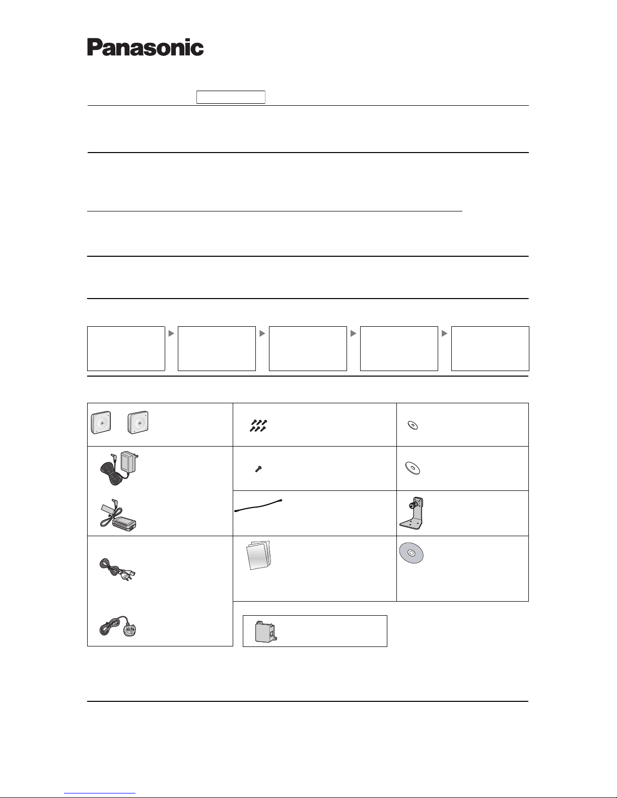
1. Confirm the following items are included in the camera’s packaging.
2. You will need the following additional items to install and configure the camera.
– a PC (see the system requirements in the Important Information document)
– For BL-C101: 2 LAN cables (CAT-5 straight cable)
For BL-C121: a LAN cable (CAT-5 straight cable)
– a router
Preparation
Confirm that you have all the
items required for installation.
Camera Diagram
Make sure you know the names
of the camera’s physical
features.
Connections
Connecting the camera to your
network and to the power outlet.
Setup
Setting up the camera
(described in the included Setup
Guide). This involves configuring
the camera so that it can be
accessed from a PC.
Mounting
Mounting or placing the camera.
Main Unit (1 pc.)
The appearance of your
camera depends on which
model you have purchased.
Screw A BL-C101 (6 pcs.)/BL-C121
(4 pcs.)
Order No. XTB4+20AFJ
Used for wall mounting the camera.
Washer S (1 pc.)
Order No. XWG26D12VW
Used when securing the safety
wire to the camera.
AC Adaptor (1 pc.)
Order No. PQLV206Y
Cord Length: About 3 m
(9 feet 10 inches)
BL-C101A/BL-C121A
Screw B (1 pc.)
Order No. XTB26+10GFJ
Used for securing the safety wire to
the camera.
Washer L (1 pc.)
Order No. XWG4F16VW
Used when securing the safety
wire to the wall.
Order No. PQLV216CE1Z
Cord Length: About 3 m
(9 feet 10 inches)
BL-C101CE/BL-C101E/BLC121CE/BL-C121E
Safety Wire (1 pc.)
Order No. PQME10080Z
Used to secure the camera when wall
mounting it.
Flexible Stand (1 pc.)
Order No. PNKL1008Z
Used to attach the camera to the
wall.
AC Cord (1pc. for BLC101CE/BL-C101E/BLC121CE/BL-C121E)
Order No. PFJA02A006Z
Cord Length: About 1.8 m
(5 feet 11 inches)
BL-C101CE/BL-C121CE
Important Information (1 pc.)
Installation Guide
(this document) (1 pc.)
Setup Guide (1 pc.)
Setup CD-ROM (1 pc.)
Order No. PQQX15704MCD
Contains the Setup Program
needed to configure the camera,
as well as the camera’s
documentation.*
*See the included Important Information
for a description of each document.
Order No. PSJA1106Z
Cord Length: About 1.8 m
(5 feet 11 inches)
BL-C101E/BL-C121E
BL-C101 Only
BL-C101 BL-C121
© Panasonic Communications Co., Ltd. 2008
PNQX1566YA KK0908CM1108
Please read this document before using the product, and save this document for future
reference. Panasonic Network Camera Website:
http://panasonic.net/pcc/products/netwkcam/
Indoor Use Only
Power Transfer Unit (1 pc.)
Order No. PNWP3C160A
Used to power the camera.
2
Camera Diagrams
*1 See 1.1 Understanding the Camera Indicator in the Troubleshooting Guide on the CD-ROM for indicator meaning.
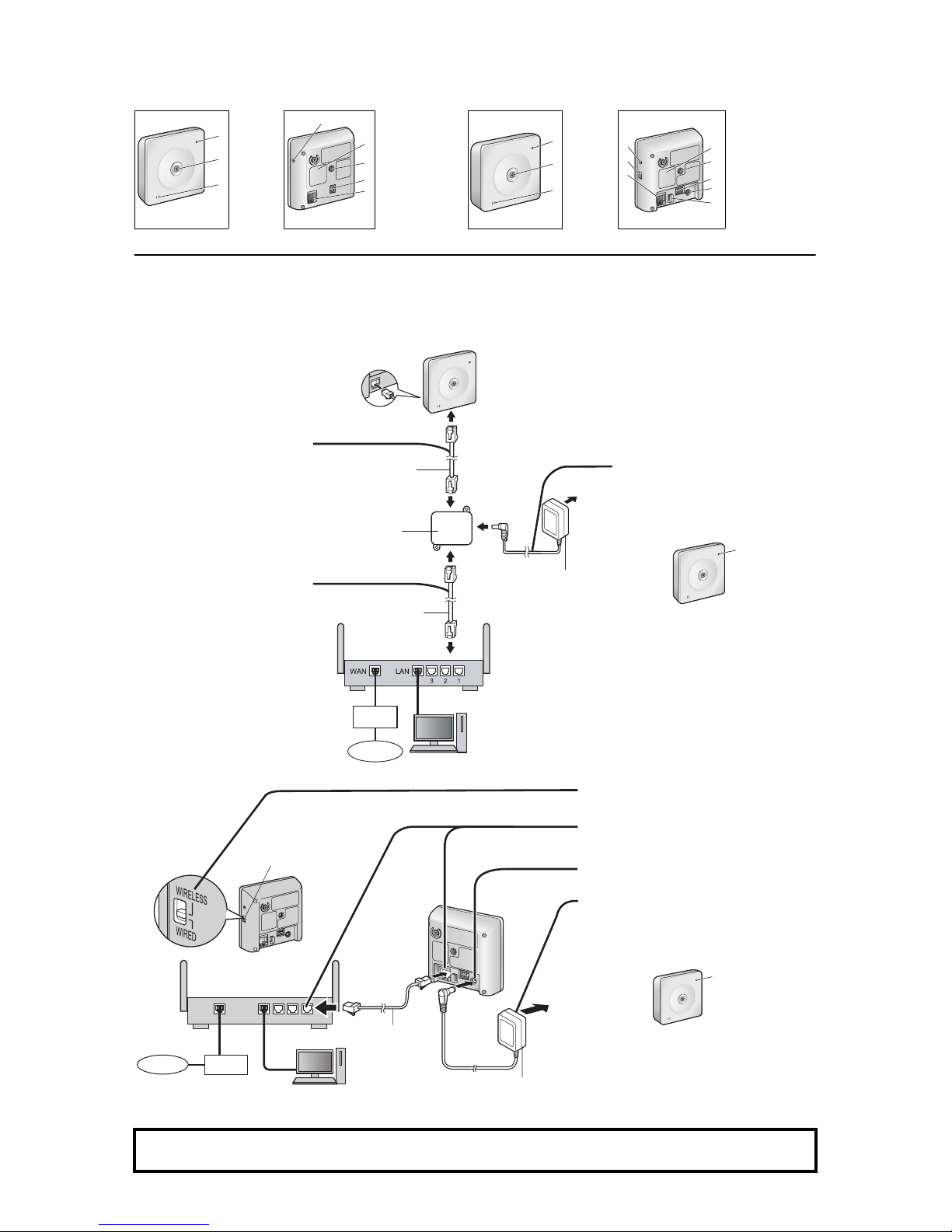
Connections
Connect the camera to your router and to the power outlet as described below.
• Before proceeding, confirm that your PC is connected to your router and can access the Internet. Also confirm that your router’s UPnP
™
feature is
enabled. (Most routers have UPnP
™
turned off by default.) Refer to the operating instructions included with your router or to the Panasonic Network
Camera website (http://panasonic.net/pcc/support/netwkcam/) for more information.
BL-C101
• Use a LAN cable that is no more than 30 m (98 feet 5 inches) long to connect the camera and the power transfer unit.
BL-C121
BL-C101 BL-C121
Front View Rear View Front View Rear View
A
B
C
Indicator
*1
Lens
Microphone
D
E
F
G
H
FACTORY DEFAULT
RESET button
Serial number label
Stand/Tripod Mounting
Hole
External INPUT
interface
DATA/POWER IN
A
B
C
Indicator
*1
Lens
Microphone
D
E
F
G
H
I
J
K
FACTORY DEFAULT
RESET button
WIRELESS/WIRED
switch
LAN port
Serial number label
Stand/Tripod Mounting
Hole
External I/O interface
DC IN jack
Hook for AC adaptor
cord
1 Connect the LAN cable to the
camera and the power transfer
unit.
2 Connect the LAN cable to the
router and the power transfer unit.
3 Connect the AC adaptor to the power
transfer unit and plug the AC adaptor
into the power outlet.
• Confirm that the indicator turns
green after about 1 minute. If it does
not turn green, see 1.2 Camera
Indicator Issues in the
Troubleshooting Guide on the CDROM.
• When you operate the camera, the
power outlet should be near the
camera and easily accessible.
• Use only specified Panasonic AC
adaptor (Order No. PQLV206Y for
BL-C101A, PQLV216CE1Z for BLC101CE, BL-C101E).
• The camera may become warm.
This is normal.
1 Confirm that the WIRELESS/WIRED switch
on the side of the camera is set to WIRED.
2 Connect the LAN cable to the camera and
the router.
3 Connect the AC adaptor cord to the DC IN
jack.
4 Plug the AC adaptor into the power outlet.
• Confirm that the indicator turns green
after about 1 minute. If it does not turn
green, see 1.2 Camera Indicator Issues in
the Troubleshooting Guide on the CDROM.
• When you operate the camera, the power
outlet should be near the camera and
easily accessible.
• Use only specified Panasonic AC adaptor
(Order No. PQLV206Y for BL-C121A,
PQLV216CE1Z for BL-C121CE, BLC121E).
• The camera may become warm. This is
normal.
After the camera’s indicator turns green, you may set up the camera. Continue by following the procedure described
in the included Setup Guide.
• If the indicator does not turn green, see 1.2 Camera Indicator Issues in the Troubleshooting Guide on the included CD-ROM.
A
B
C
E
F
G
D
H
A
B
C
D
E
F
G
H
I
J
K
LAN cable
(Cat-5 straight cable)
LAN cable
Power transfer unit
AC adaptor
Router
Modem
Internet
PC
Green
WAN
4321
LAN
Router
Internet
Modem
PC
LAN cable
(Cat-5 straight cable)
WIRELESS/WIRED switch
AC adaptor
Green
To the power
outlet
(For BLC101CE/
BL-C101E
use an AC cord)
To the power
outlet
(For BLC121CE/BLC121E use an
AC cord)
 Loading...