

Page 1
Color Video Camera
AW-E560
Before attempting to connect or operate this product,
please read these instructions completely.
(Lens : Purchased locally)
Page 2
Warning:
This equipment generates and uses radio frequency energy and if not installed and used properly, i.e., in strict
accordance with the instruction manual, may cause harmful
interference to radio communications. It has been tested
and found to comply with the limits for a Class A computing
device pursuant to Subpart J of Part 15 of FCC Rules,
which are designed to provide reasonable protection
against such interference when operated in a commercial
environment.
This digital apparatus does not exceed the Class A limits for
radio noise emissions from digital apparatus set out in the
Radio Interference Regulations of the Canadian Department
of Communications.
WARNING:
TO PREVENT FIRE OR SHOCK HAZARD, DO NOT EXPOSE THIS APPLIANCE TO RAIN OR MOISTURE.
The lightning flash with arrowhead symbol, within an equilateral triangle, is
intended to alert the user to the presence of uninsulated "dangerous voltage"
within the product's enclosure that may
be of sufficient magnitude to constitute a
risk of electric shock to persons.
The exclamation point within an equilateral triangle is intended to alert the user
to the presence of important operating
and maintenance (servicing) instructions
in the literature accompanying the appliance.
The serial number of this product may be found on the bottom of the unit.
You should note the serial number of this unit in the space
provided and retain this book as a permanent record of your
purchase to aid identification in the event of theft.
Model No. AW-E560
Serial No.
CAUTION:
TO REDUCE THE RISK OF ELECTRIC SHOCK, DO
NOT REMOVE COVER (OR BACK). NO USER SERVICEABLE PARTS INSIDE.
REFER SERVICING TO QUALIFIED SERVICE PERSONNEL.
CAUTION
RISK OF ELECTRIC SHOCK
DO NOT OPEN
SA 1965
SA 1966
For U.S.A
For CANADA
Page 3

-1-
CONTENTS
PREFACE ............................................................................................................................................................................................ 2
FEATURES .......................................................................................................................................................................................... 2
SPECIAL NOTES ON OPERATION .................................................................................................................................................... 3
PRECAUTIONS ................................................................................................................................................................................... 4
MAJOR OPERATING CONTROLS AND THEIR FUNCTIONS ............................................................................................................ 6
LENS MOUNTING .............................................................................................................................................................................. 11
FLANGE BACK ADJUSTMENT .......................................................................................................................................................... 12
IRIS GAIN CONTROL IN A LENS ....................................................................................................................................................... 12
CONNECTIONS .................................................................................................................................................................................. 13
ADJUSTMENT .................................................................................................................................................................................... 25
OPERATION MODE SETTING ............................................................................................................................................................ 31
MENU ITEM SETTING ........................................................................................................................................................................ 33
INITIAL SET MENU SETTING ............................................................................................................................................................. 36
USER SETUP MENU SETTING ........................................................................................................................................................... 43
CAMERA INSTALLATION ................................................................................................................................................................... 48
CAMERA ID SETTING ........................................................................................................................................................................ 49
TIME DATE SETTING ......................................................................................................................................................................... 52
RANGE OF SETUP/INITIAL SET AND THEIR INITIAL VALUE ............................................................................................................ 54
RANGE OF SCENE FILE/USER SET AND THEIR INITIAL VALUE ..................................................................................................... 55
SPECIFICATIONS ............................................................................................................................................................................... 59
STANDARD ACCESSORIES ............................................................................................................................................................... 60
OPTIONAL ACCESSORIES ................................................................................................................................................................ 60
Page 4

-2-
PREFACE
The Panasonic AW-E560 is a digital signal processing
color video camera that incorporates three 1/2” CCDs. A
digital video signal processing system is packed in a compact, lightweight body while assuring high picture quality,
high reliability and high performance.
System setup and adjustments can be easily performed by
setup menu.
Connection to peripheral devices, such as an RCU and an
RCB, enables a wide variation of system configurations.
The lens and the camera pan/tilt unit can be remote controlled when the camera is connected to an RCU with
optional multiplex adaptor WV-PS550.
Connection to an RCU for camera control and power supply can be simply done with a coaxial cable through an
optional adaptor.
FEATURES
1. Digital video signal processing for high quality, high
reliability, high performance, lightweight and compact
size.
2. Resolution: 800 lines (HIGH BAND DTL : ON), S/N
ratio: 62dB
3. Minimum illumination: 5 lux (F1.4, +18dB)
4. SET UP menu for system check and readjustments.
5. Built-in automatic controls, including ATW, ELC, and
AGC
6. CCD readout is switchable between field and frame
modes. Vertical resolution can be stepped up in
frame mode and it is effective for shooting still objects.
7. Any of R/G/B, Y/C, Y/PB/PR and composite can be
selected as an output signal.
8. Thanks to the built-in synchronized scanning system,
noiseless pictures are available from computer graphics.
9. Various correction circuits permit video reproduction
with highest fidelity.
10. Chroma aperture correction enables clear shots of
dark color objects.
11. 2 Dimensional lowpass filter reduces spurious signals.
12. A dark detail circuit provides natural edge correction
to any object in a dark scene.
Page 5

-3-
13. A digital highlight compression circuit reproduces natural dynamic ranges.
14. A digital color matrix enables high fidelity color
images.
15. The optimum operation mode for each of your specific
applications can be selected.
16. The scene file automatically sets up the most appropriate shooting conditions.
17. System setup parameters, such as SMPTE/full color
bar, date and time are indicated on the monitor
screen.
18. Remote control with an RCU or RCB.
SPECIAL NOTES ON OPERATION
• Turn power off before connecting or disconnecting
cables.
• Connection or disconnection of any studio cable, RCB
cable or other cable to any unit of equipment must be
performed while power is off.
• While the camera is automatic mode;
Shooting of bright objects in ELC operation mode may
result in a smeared picture unique to the CCD.
The ATW function under fluorescent illumination can
adversely change the white balance.
Page 6

-4-
PRECAUTIONS
DONT'S
• Do not attempt to disassemble the camera, Remote
Control Unit (RCU) or other units. In order to prevent
electric shock, do not remove screws or covers.
There are no user-serviceable parts inside.
• Do not abuse the camera. Avoid striking, shaking,
etc. The camera contains sensitive components
which could be damaged by improper handling or
storage.
• Do not let the lens remain uncapped when the camera
is not in use. If the lens is not installed, do not leave
the lens mount hole uncovered.
• Do not touch the surface of the lens or prism with your
fingers.
• Do not use strong of abrasive detergents when cleaning the camera body.
DO'S
• Do refer any servicing to qualified service personnel.
• Do handle the camera with care.
• Do protect the precision made lens by placing the
lens cap over the lens when the camera is not in use.
If the lens is not installed, protect the surface of the
prism by placing the body cap into the lens mount
hole.
• Do use a mild blower or lens cleaning tissue designed
for coated lenses, to clean the surface of the lens or
prism in the event that it should become dirty.
• Do use a dry cloth to clean the camera if it is dirty. In
case the dirt is hard to remove, use mild detergent
and wipe gently.
Page 7

-5-
• Do not aim the camera toward the sun, no matter
whether it is turned on or not.
• Do not expose the camera or Remote Control Unit
(RCU) to rain or moisture, and do not try to operate the
equipment in wet areas. Do not operate the camera or
RCU if it becomes wet.
• Do not operate the camera or Remote Control Unit
(RCU) outdoors during a lightning storm.
• Do not use the camera in an extreme environment
where high temperatures or high humidity exist.
• Do not leave the camera and Remote Control Unit
(RCU) turned on when not in use. Do not unnecessarily turn the camera power on and off repeatedly. Do
not block the ventilation slots.
• Do use caution when operating the camera in the
vicinity of spot lights or other bright lights, as well as
light reflecting objects and surfaces.
• Do take immediate action if ever the camera or RCU
should become wet. Turn the power off and have the
unit checked by an authorized service facility.
• Do follow normal safety precautions to avoid personal
injury.
• Use the camera in an environment where the temperature is within 14°F - 113°F (−10°C - +45°C), and the
relative humidity is within 30% - 90%.
• Always turn the power off when the camera is not
going to be used. Operate the camera and Remote
Control Unit (RCU) only when there is adequate ventilation.
Page 8
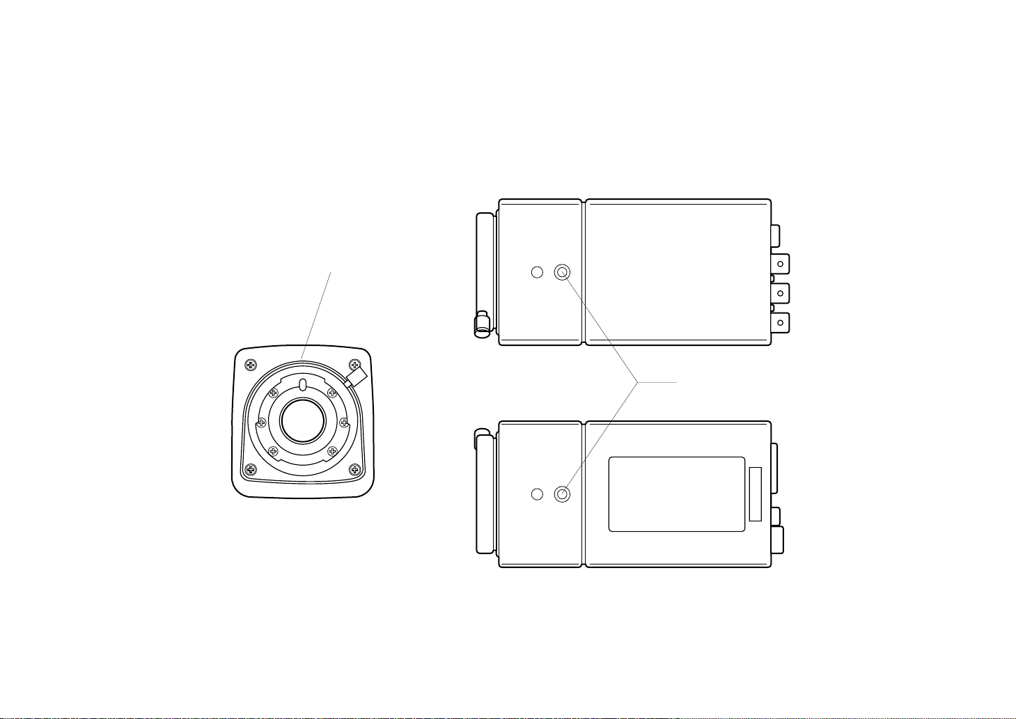
-6-
1
2
<Front View>
<Top View>
<Bottom View>
MAJOR OPERATING CONTROLS AND THEIR FUNCTIONS
Page 9
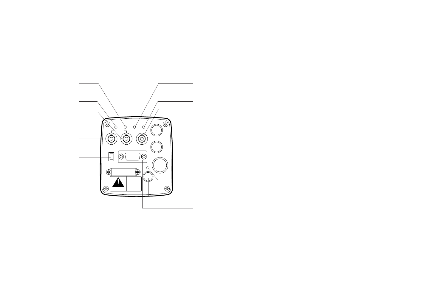
-7-
1. Lens Mount
1/2" standard bayonet type lens or a microscope
adaptor can be mounted.
2. Mounting Hole
A screw hole (1/4” - 20 UNC) for mounting the camera
on a wall, ceiling with a mounting bracket or tripod.
3. Page Switch (PAGE)
A menu will appear on the monitor screen when this
switch is pressed for around 2 seconds. Pressing the
switch advances the menu page.
4. Item Switch (ITEM/AWC)
Any of the items shown in the menu can be selected
with this switch. When the menu is not displayed or
the camera is in shooting mode, the automatic white
balance control can be set with this switch.
5. Up Switch (UP/ABC)
While the menu is displayed, any setting can be
brought up to a higher value with this switch. When
the menu is not displayed or the camera is in shooting
mode, the automatic black balance control can be set
with this switch.
6. Down Switch (DOWN/BAR)
While the menu is displayed any setting can be
brought down to a lower value with this switch. When
the menu is not displayed or the camera is in shooting
mode, the color bar and the shooting conditions are
alternately indicated by pressing the switch.
ZOOM/FOCUS
REMOTE
EXT DC IN
PAGE
ITEM
(AWC)UP(ABC)
DOWN
(BAR)
IRIS
SEE MANUAL
CAUTION
CONNECT TO SPECIFIED
CLASS 2 POWER SUPPLY
ONLY SEE MANUAL
VBS/HD
75 
VD
VIDEO/RGB
CONTROL
VIDEO OUTG/L IN
ON
OFF
4
3
5
6
7
8
9
!0
!1
!2
!3
!4
!5
!6
!7
Page 10
-8-
7. Video Output Connector (VIDEO OUT)
A composite video signal is provided at this connector.
8. Iris Connector (IRIS)
Input terminal for lens with an iris control function.
Some lenses may require an optional lens extension
cable for connection.
9. Zoom/Focus Connector (ZOOM/FOCUS)
Input terminal for lens with zoom and focus function
that can be remote controlled.
Pin No. Signal Pin No. Signal
1 Not Used 7 Iris F
2 Not Used 8 Auto/Remote Control
3 GND 9 Not Used
4 Auto/Manual Control 10 Not Used
5 Iris Control 11 Not Used
6 Lens P 12 Not Used
<Front View>
Iris Connector (IRIS)
Pin No. Signal Pin No. Signal
1 Not Used 7 Voltage Common
2 Not Used 8 Focus Control
3 GND 9 Zoom Control
4 Not Used 10 Not Used
5 Not Used 11 Lens +V
6 +12 V 12 Lens −V
<Front View>
Zoom/Focus Connector (ZOOM/FOCUS)
o
q
i
w
u
e
ytr
!2
!0
!1
o
q
iw
u
e
y
t
r
!2
!0
!1
Page 11
-9-
Pin No. Signal Pin No. Signal
1 Composite Video Output 11 RCB Transmission
2 GND 12 Control (Command)
3 G/Y/Y Output 13 +9.2 V RCB
4 R/PR/C Output 14 DC 12 V Output
5 GND 15 DC 12 V Input
6 RCB Detect 16 DC 12 V Input
7 EXT SUB In 17 RCB Reception
8 B/PB Output 18 GND
9 GND 19 GND
10 G/L Input 20 Not used
<Front View>
Remote Connector (REMOTE)
<Front View>
DC Input Connector (EXT DC IN)
10. Remote Connector (REMOTE)
Input terminal dedicated to control signals from the
optional Remote Control Box (WV-CB700A) and the
Remote Control Unit (WV-RC700A).
* WV-CB700A is connected through the optional con-
version cable (WV-CA20T10).
* WV-RC700A is connected through the optional con-
version cable (WV-CA26T20).
11. Power Indicator
Red LED lamp lights to indicate that the specified DC
power is supplied to the camera.
12. DC Input Connector (EXT DC IN)
12 V DC is supplied through the 4-pin connector provided with the camera.
Pin No. Signal
1 +12 V In
2 +12 V In
3 Ground
4 Ground
r
oqiwueyt
!2!0!1!3!4!5!6
@0!9!8!7
r
q
e
w
Page 12

-10-
13. Video/RGB Output Connector (VIDEO/RGB)
Composite/Y signal, RGB/Y-C/component signal and
synchronizing signal are output from this connector.
* Refer to Page 41 for signal selection.
The optional cable WV-CA9T5 or WV-CA9T9 must be
used for connection to this connector.
Pin No. Signal Pin No. Signal
1 GND 6 SY/COMP
2 GND 7 SYNC
3 R/PR/C 8 GND
4 G/Y/Y 9 C/NC
5 B/PB/NC
<Front View>
The multiplex adaptor WV-PS550 is connected to this
connector when using a coaxial multiplex system. The
WV-RC700A and WV-PS550 can be connected with a
coaxial cable.
Pin No. Signal Pin No. Signal
1 Composite Video Output 15 Defroster Control Output
2 GND 16 Wiper Control Output
3 Not Used 17 Common
4 Not Used 18 +5.2 V Output
5 G/L Input 19 GND
6 GND 20 −5.2 V Output
7 WV-PS550 Detect 21 GND
8 PS Transmission 22 GND
9 PS Reception 23 DC 12 V Input
10 GND 24 DC 12 V Input
11 UP Control Output 25 Not Used
12 Down Control Output 26 +9.2 V Output
13 Left Control Output 27 GND
14 Right Control Output 28 GND
<Front View>
Control Connector (CONTROL)
Video/RGB Output Connector (VIDEO/RGB)
14. Control Connector (CONTROL)
Control signals for a pan/tilt unit come to this connector when a pan/tilt unit controller is connected to the
camera through the Remote Control Unit WV-RC700A
with a multicable.
⁄4⁄3⁄2⁄1⁄0.,mnbcxz
¤8¤7¤6¤5¤4¤3¤2¤1¤0⁄9⁄8⁄7⁄6⁄5
v
oqiwuey
tr
Page 13
-11-
15. G/L Signal 75-ohm ON/OFF Switch (75Ω ON/OFF)
A terminating switch for G/L signals at Items 16 and
17.
16. G/L VBS/HD Input Connector (G/L IN - VBS/HD)
Signals synchronized with the reference signal are to
be supplied to this connector when the camera is to
be synchronized with the reference signal. VBS/BB,
VS and HD signals are to be automatically determined.
17. G/L VD Input Connector (G/L IN - VD)
Same as Item 16 except that VD signal is to be supplied when input signal at Item 16 is HD.
LENS MOUNTING
Lenses of any make can be mounted on the camera as
long as they are equipped with a 1/2” standard bayonet.
1. Mounting
Rotate the lens fixing ring knob counterclockwise and
remove the lens mount cap. Mount the lens on the
camera and rotate the lens fixing ring knob clockwise
in order to fix the lens securely. Then connect the lens
cable to the IRIS Connector on the back panel of the
camera.
* Use the lens extension cable WV-CA12T12 (6”/15cm)
if your lens cable is too short.
Lens fixing ring knob
Page 14
-12-
FLANGE BACK ADJUSTMENT
1. Fully open the iris by shooting a dark object. (Iris
selection switch should be set to M.)
2. Loosen the flange back lock knob.
3. Aim the camera at any object over 2 meters away from
the camera.
4. Set the lens to its TELE end first and adjust its focus
with the focus ring.
5. Set the lens to its widest angle next and adjust its
focus with the flange back adjust ring.
6. Adjust the focus ring and the flange back adjust ring
alternately for the best focus within the zooming
range.
Tighten the flange back lock knob upon completion of
focusing.
7. Turn the iris selection switch to Position A.
* The figure represents Lens PH15X7BKRS2U.
IRIS GAIN CONTROL IN A LENS
An iris gain control hole is usually provided in the front of a
lens. Adjustment of the iris gain, with a screwdriver
through the hole may be done as follows. (Shape and
location of the hole may vary depending on the lens
make.)
1 Turn the iris selection switch to Position A (AUTO).
2 Rotate the iris gain control to the maximum gain but in
a range where no hunting or oscillating of the iris ring
develops.
* The figure represents Lens PH15X7BKRS2U.
Flange back
adjust ring
Flange back
lock knob
Focus ring
Iris gain control
Automatic iris power zoom lens
Page 15
ZOOM/FOCUS
REMOTE
EXT DC IN
PAGE
ITEM
(AWC)UP(ABC)
DOWN
(BAR)
IRIS
SEE MANUAL
CAUTION
CONNECT TO SPECIFIED
CLASS 2 POWER SUPPLY
ONLY SEE MANUAL
VBS/HD
75 
VD
VIDEO/RGB
CONTROL
VIDEO OUTG/L IN
ON
OFF
-13-
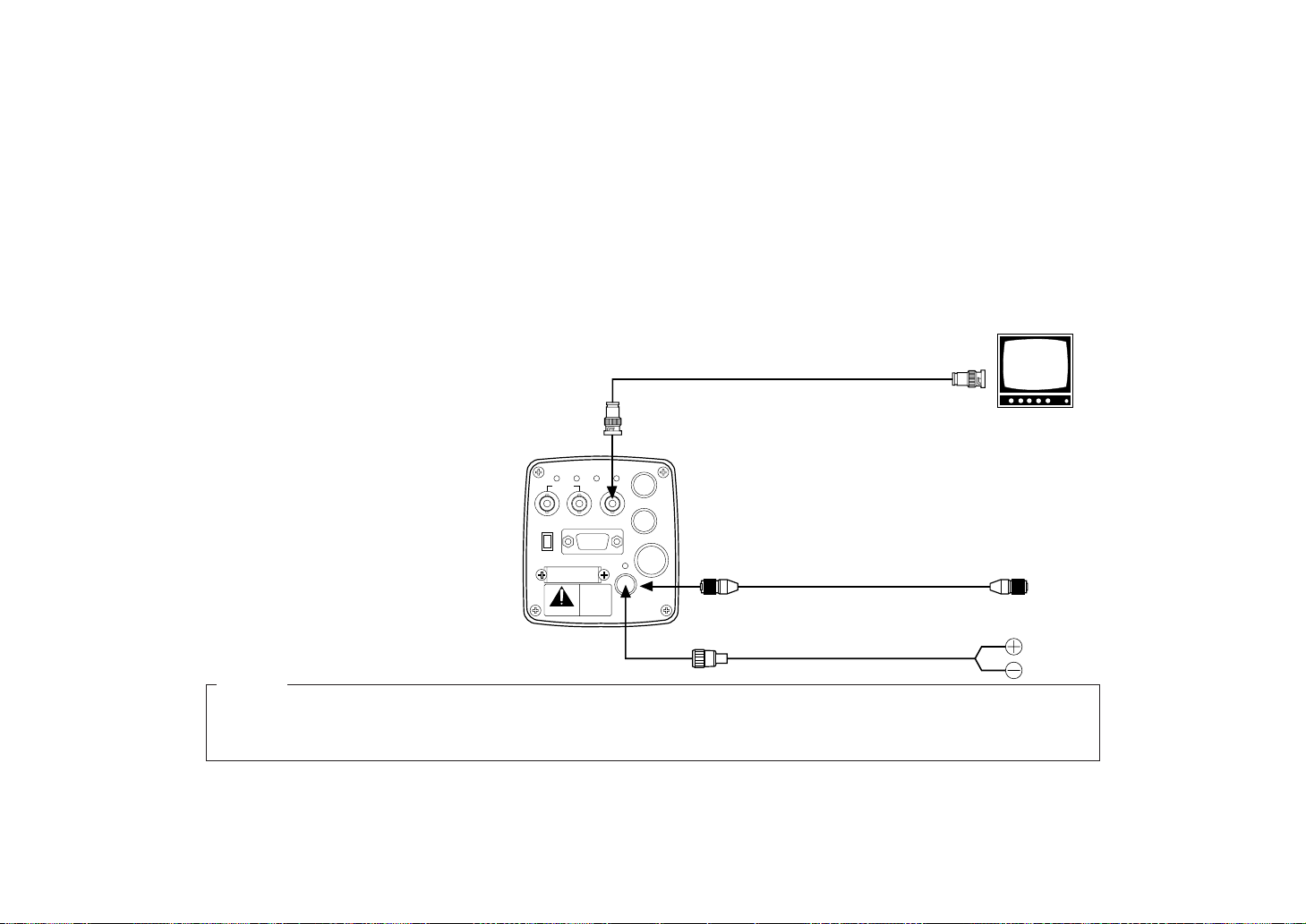
■ CONNECTION OF DEVICE WITH A COMPOSITE INPUT CONNECTOR
CONNECTIONS
Caution :
The connection and installation should be done by qualified service personnel or system installers.
Refer any servicing to qualified service personnel.
1. Connect this to a 12V DC class 2 power supply only.
2. To prevent fire or shock hazard, the UL listed wire VW-1, style 1007 should be used as for the cable for 12V DC Input
Connector.
Cautions
• Connection to any device which
has a composite input connector, such as a video monitor or
a VCR, must be made through
the VIDEO OUT Connector.
• Power supply to the camera
must be through the optional
Conversion Cable WV-CA4C4P
or a power cable assembled
with the connector provided
with the camera.
• Power source must be able to
continuously supply 12 V DC,
2A nominally.
VIDEO OUT
Connector
Power supply:
12 V DC, 2A min.
Video monitor
Conversion Cable WV-CA4C4P
VIDEO IN
To AG-B640
or AU-B110
or
75Ω coaxial cable
Power Cable (locally purchased)
Page 16
-14-
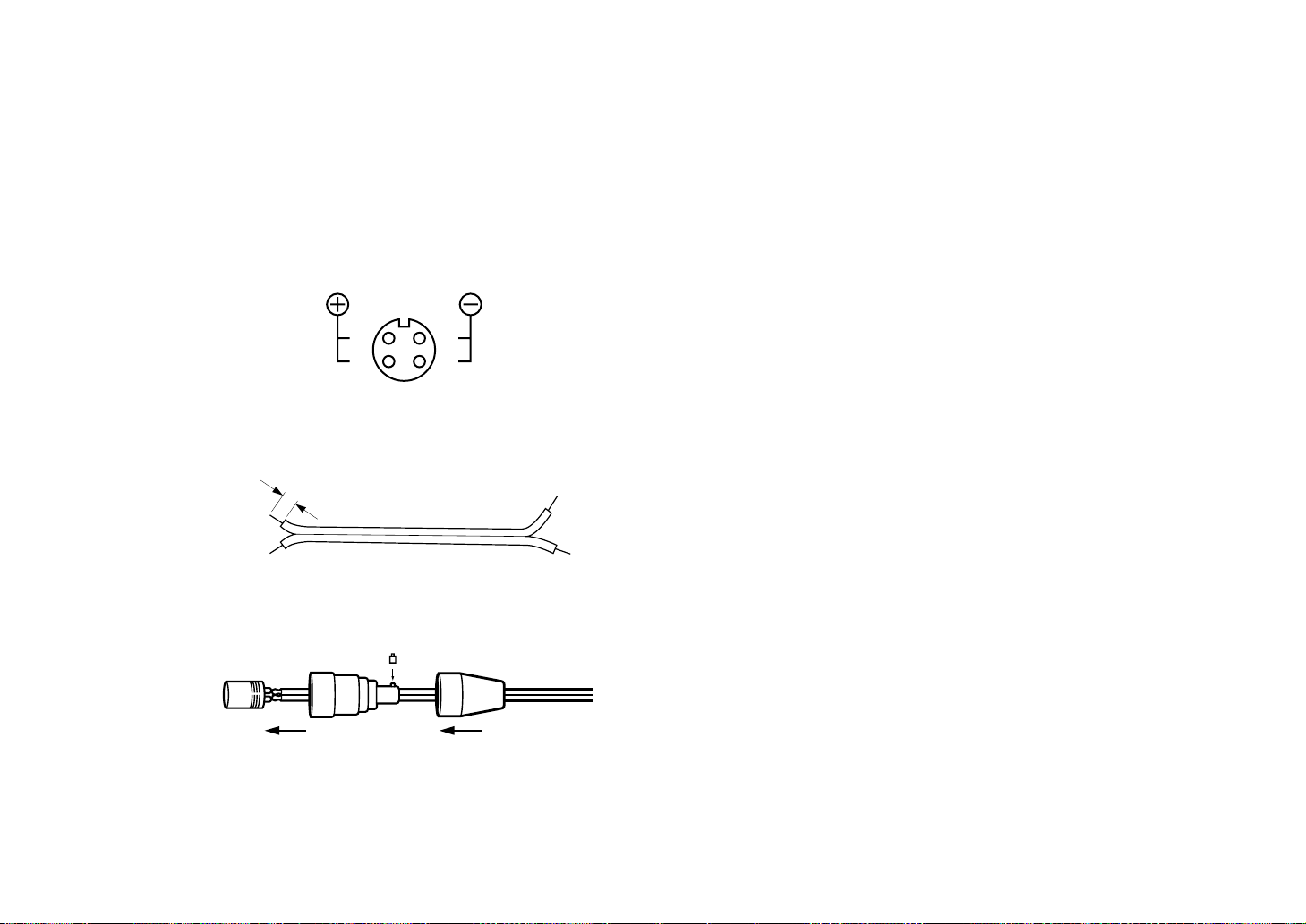
How to assemble the power cable:
The power cable is to be assembled with the connector
provided with the camera.
<Connector pin layout>
1. Prepare the wire.
2. Fix with a screw if necessary.
Put the casing and the rubber bushing on after soldering wires to the connector.
Caution :
To prevent fire or shock hazard, the UL listed wire VW1, style 1007 should be used as for the cable for 12V
DC Input Connector.
1
2
4
3
<Wire view>
AWG24 or larger
3/16"
(5 mm)
Page 17
-15-
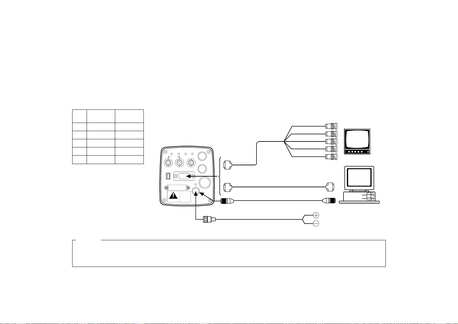
Input signals to an RGB monitor or image processor must
be supplied from the VIDEO/RGB connector through the
optional D Sub/BNC cable WV-CA9T5 or D Sub/D Sub
cable WV-CA9T9.
NOTES:
• Output signals at the VIDEO/RGB connector can be
selected from the INITIAL SET menu.
• SYNC level can be selected from the INITIAL SET
menu.
■ CONNECTION OF DEVICE WITH AN RGB MONITOR OR AN IMAGE PROCESSOR
Pin Wire's Output
No. Color Signal
3 Red R/PR/C
4 Green G/Y/Y
5 Blue B/PB
6 White Y/COMP
7 Black SYNC
WV-CA9T5 Cable Information
1. Connect this to a 12V DC class 2 power supply only.
2. To prevent fire or shock hazard, the UL listed wire VW-1, style 1007 should be used as for the cable for 12V DC Input
Connector.
Cautions
ZOOM/FOCUS
REMOTE
EXT DC IN
PAGE
ITEM
(AWC)UP(ABC)
DOWN
(BAR)
IRIS
SEE MANUAL
CAUTION
CONNECT TO SPECIFIED
CLASS 2 POWER SUPPLY
ONLY SEE MANUAL
VBS/HD
75 
VD
VIDEO/RGB
CONTROL
VIDEO OUTG/L IN
ON
OFF
RGB monitor or
image processing
device
Red
Green
Blue
Black
White
WV-CA9T5
WV-CA9T9
or
Power supply:
12 V DC, 2A min.
Computer
RGB/SYNC
connector
RGB/SYNC
connector
Conversion Cable WV-CA4C4P
To AG-B640 or AU-B110
or
Power Cable (locally purchased)
Page 18
-16-
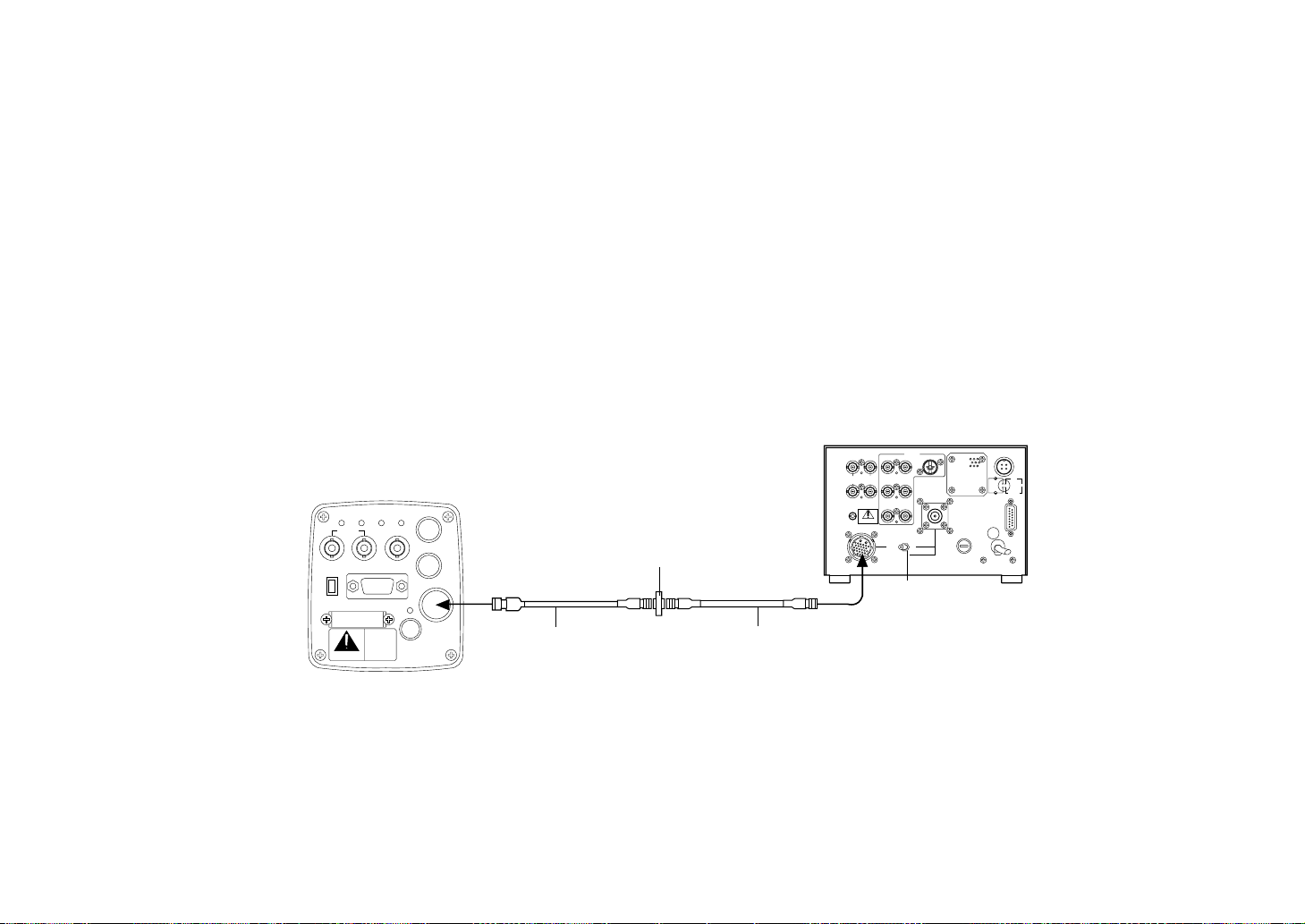
Connection to the RCU (WV-RC700A) is made through the
optional conversion cable WV-CA26T20 and a studio
cable.
1. Turn RCU power off before connecting cables.
2. Set the cable selection switch of the RCU to MULTI.
3. Connect the 20 pin connector of the conversion cable
to the REMOTE Connector of the camera. The conversion cable and the studio cable must be connected
with the connector supplied as a standard accessory
with the conversion cable.
4. Turn RCU power on and the power indicator lamp will
light. The camera can now be remote controlled by
the RCU.
NOTES:
• Maximum extension length: 300 meters
(Studio cables must be connected with joint adaptor
WV-CA26T26.)
• Use only the specified cables.
■ CONNECTION OF A REMOTE CONTROLLER (RCU AND A STUDIO CABLE)
GEN-LOCKINAUX
IN
AUTO
75 ¶/Hi-Z
AUTO
75 ¶/Hi-Z
R/PR /C
OUT OUT
AUDIO
SEE MANUAL
VIDEO 1
G/Y/Y VIDEO 2
B/PB /B SYNC
S-VIDEO
1 4
2 3
TALLY
CAMERA (MULTI)
CABLE SELECT
FUSE
125V 2A
TALK
INCOM
RECEIVE
CONTROL
TALLY & INCOM
MULTI OVP
MPX
MPX
OUTPUT
ZOOM/FOCUS
REMOTE
EXT DC IN
PAGE
ITEM
(AWC)UP(ABC)
DOWN
(BAR)
IRIS
SEE MANUAL
CAUTION
CONNECT TO SPECIFIEDCONNECT TO SPECIFIED
CLASS 2 POWER SUPPLYCLASS 2 POWER SUPPLY
ONLY SEE MANUALONLY SEE MANUAL
VBS/HD
75 
VD
VIDEO/RGB
CONTROL
VIDEO OUTG/L IN
ON
OFF
Connector supplied
with WV-CA26T20
Studio cable (Option)
WV-CA26U15 (50 ft/15 m)
WV-CA26U30 (100 ft/30 m)
WV-CA26U100 (330 ft/100 m)
Set to MULTI
WV-RC700A
Conversion cable (Option)
WV-CA26T20 (10 ft/3 m)
Page 19
-17-
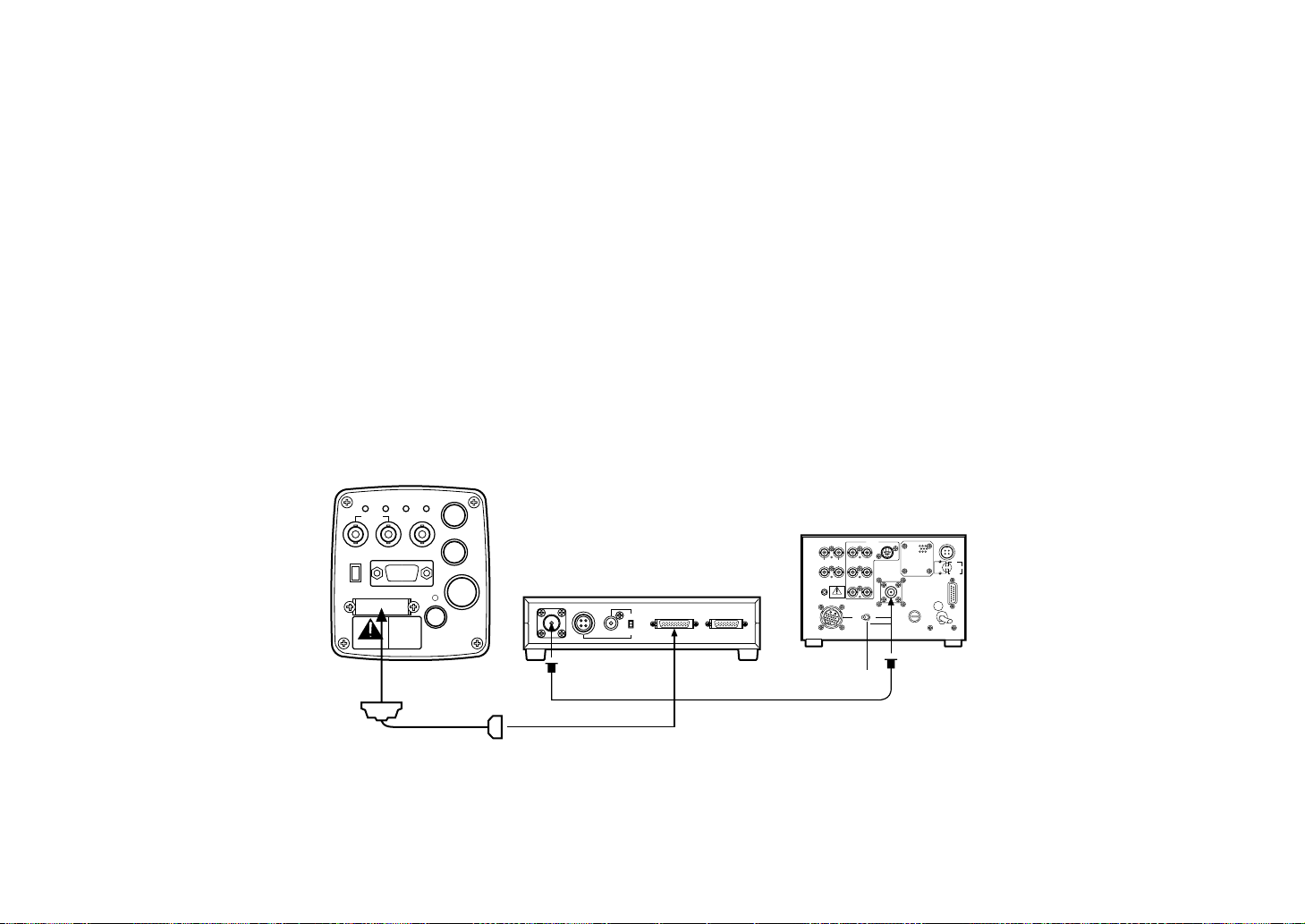
■ CONNECTION OF A REMOTE CONTROLLER (RCU AND A COAXIAL MULTIPLEX SYSTEM)
The optional multiplex adaptor WV-PS550 is used for
connection of a coaxial multiplex system.
1. Turn RCU power off before connecting cables.
2. Connect the optional multiplex adaptor WV-PS550 to
the control connector of the camera through the standard accessory cable supplied with the WV-PS550.
3. Set the cable selection switch of the RCU to VP.
4. Connect the MPX connector of the multiplex adaptor
and that of the RCU with a coaxial cable (Belden 8281
or equivalent).
5. Turn RCU power on and the power indicator lamp will
light. The camera can now be remote controlled by
the RCU.
NOTES:
• Use only model WV-RC700A (with WV-CB700A) as an
RCU.
• A coaxial multiplex system cannot be used with a studio 26-pin cable.
• R/G/B, Y/C and Y/PR/PB signals cannot be transmitted
through this system. Use a studio cable if any of
these signals is required.
• The maximum cable extension length allowed for this
system is 300 meters.
GEN-LOCKINAUX
IN
AUTO
75 ¶/Hi-Z
AUTO
75 ¶/Hi-Z
R/PR /C
OUT OUT
AUDIO
SEE MANUAL
VIDEO 1
G/Y/Y VIDEO 2
B/PB /B SYNC
S-VIDEO
14
23
TALLY
CAMERA (MULTI)
CABLE SELECT
FUSE
125V 2A
TALK
INCOM
RECEIVE
CONTROL
TALLY & INCOM
MULTI OVP
MPX
MPX
OUTPUT
ZOOM/FOCUS
REMOTE
EXT DC IN
PAGE
ITEM
(AWC)UP(ABC)
DOWN
(BAR)
IRIS
SEE MANUAL
CAUTION
CONNECT TO SPECIFIED
CLASS 2 POWER SUPPLY
ONLY SEE MANUAL
VBS/HD
75 
VD
VIDEO/RGB
CONTROL
VIDEO OUTG/L IN
ON
OFF
AUDIO
CONTROL OUTCAMERA
MPX DATA IN AUDIO IN
DATA
Supplied with
WV-PS550
multiplex adaptor WV-PS550
Set to VP
WV-RC700A
Coaxial cable
(Belden 8281 or equivalent)
Page 20

ALL 1
2
USER SET
ZOOM/FOCUS
REMOTE
EXT DC IN
PAGE
ITEM
(AWC)UP(ABC)
DOWN
(BAR)
IRIS
SEE MANUAL
CAUTION
CONNECT TO SPECIFIED
CLASS 2 POWER SUPPLY
ONLY SEE MANUAL
VBS/HD
75 
VD
VIDEO/RGB
CONTROL
VIDEO OUTG/L IN
ON
OFF
-18-
■ CONNECTION OF A REMOTE CONTROL BOX (RCB)
The RCB (WV-CB700A) and the camera must be connected with the optional conversion cable WV-CA20T10.
1. Turn RCB power off before connecting cables.
2. Connect the 20 pin connector of the conversion cable
to REMOTE connector of the camera. The 10-pin connector must be connected to the RCB accessory
cable or an optional RCB cable.
3. Turn RCB power on and the camera can be remote
controlled by the RCB.
NOTES:
• The monitor output signals of the RCB attenuate and
deteriorate with cable length. It is recommended that
the signals from the monitor output be used for monitoring purpose only.
• No gen-lock signal is available from the RCB.
Power supply:
12 V DC, 2A min.
Video signals
RCB, Rear view
The RCB accessory cable, WV-CA10B25
(80 ft/25 m) or WV-CA10B50 (160 ft/50 m).
WV-CB700A
1. Connect this to a 12V DC class 2 power supply only.
2. To prevent fire or shock hazard, the UL listed wire VW-1,
style 1007 should be used as for the cable for 12V DC
Input Connector.
Cautions
Conversion Cable WV-CA4C4P
To AG-B640
or AU-B110
or
Power Cable (locally purchased)
Conversion cable
WV-CA20T10 (Option)
(3 ft/ 1m)
Page 21

-19-
■ CONNECTION WITH MULTIPLE CAMERAS
■ An example of connection for VBS/BB input (Color lock
mode).
• A special effect generator is used as the source of refer-
ence signals.
• Supply a synchronizing signal (VBS/BB) to the GEN-LOCK
Connectors of both the RCU and the camera.
• Adjust the SC phase and H phase at the Program Out
Connector.
There are two other modes such as VS input (No color lock
mode) and HD/VD input (monochrome mode), which
can be selected for your application.
GEN-LOCKINAUX
IN
AUTO
75
/Hi-Z
AUTO
75¶/Hi-Z
R/PR /C
OUT OUT
AUDIO
SEE MANUAL
VIDEO 1
G/Y/Y VIDEO 2
B/PB /B SYNC
S-VIDEO
14
23
TALLY
CAMERA (MULTI)
CABLE SELECT
FUSE
125V 2A
TALK
INCOM
RECEIVE
CONTROL
TALLY & INCOM
MULTI OVP
MPX
MPX
OUTPUT
GEN-LOCKINAUX
IN
AUTO
75
/Hi-Z
AUTO
75
/Hi-Z
R/PR /C
OUT OUT
AUDIO
SEE MANUAL
VIDEO 1
G/Y/Y VIDEO 2
B/PB /B SYNC
S-VIDEO
14
23
TALLY
CAMERA (MULTI)
CABLE SELECT
FUSE
125V 2A
TALK
INCOM
RECEIVE
CONTROL
TALLY & INCOM
MULTI OVP
MPX
MPX
OUTPUT
8 7 6 5 4 3 2 1
EXT DC INPUT EXT PATTERN INPUT
8
75
Hi-Z775
Hi-Z675
Hi-Z575
Hi-Z475
Hi-Z375
Hi-Z275
Hi-Z175
Hi-Z
DSK
75
Hi-Z
GENLOCK
75
Hi-ZGR
B
TALLY & INTERCOM
VIDEO INPUT
CHROMAKEY
12
PAL SQUARE
3
BL
HD
SC
SYNC
VD
BFP
VIDEO OUTPUTSYNC OUTPUT
BLACK BURST
PREVIEW
PROGRAM
Preview
Program
Video signal
Line out
AUX IN
Black burst
VIDEO OUT
Tally & intercom
IN
IN
IN
IN
IN
OUT
OUT
OUT
Tally &
intercom
Tally &
intercom
Video signal 1
Video signal 2
Video
signal 3
Gen-lock
VIDEO OUT
Selectable
MPX
WV-PS550
WV-PS550
MPX
MPX
Video
out
VTR
RCU
VTR
RCU
Genlock
Genlock
AUX IN
Gen-lock
(composite sync)
Special
effects
generator
Selectable
OUT
Page 22

-20-
CONNECTION OF COMPUTER INTERFACE ADAPTOR
The system shown here can remotely control this camera by using the Computer Interface Adaptor WJ-PC500.
The software required for this operation should be obtained locally.
Please contact qualified service personnel for this software.
PC Mode System 1-1
CAMERA 2
IN
MONITOR
OUT
G/L IN
CAMERA 1 IN
DC12V IN
CAMERA SELECT
RS-232C/422
ZOOM/FOCUS
REMOTE
EXT DC IN
PAGE
ITEM
(AWC)UP(ABC)
DOWN
(BAR)
IRIS
SEE MANUAL
CAUTION
CONNECT TO SPECIFIED
CLASS 2 POWER SUPPLY
ONLY SEE MANUAL
VBS/HD
75 
VD
VIDEO/RGB
CONTROL
VIDEO OUTG/L IN
ON
OFF
• Connect the WV-CA20T10
Conversion Cable and WV-CA
10B02, WV-CA10B25 or WVCA10B50 10/10-pin Cable
between the Camera 1 Input
Connector on the Computer
Interface Adaptor and Remote
Connector of this camera.
• Connect the coaxial cable
between the Monitor Output
Connector on the Computer
Interface Adaptor and the
video input connector of the
monitor.
• Connect the 25/9-pin conversion cable between the RS232C/422 Connector on the
Computer Interface Adaptor
and computer.
25/9-pin Conversion Cable
for RS232C (straight)
Conversion Cable
WV-CA20T10 (1m)
Computer
Monitor
AW-E560
WJ-PC500
WV-CA10B02 (2m)
WV-CA10B25 (25m)
WV-CA10B50 (50m)
Note: The decrement of the video signal from the Monitor
Output Connector on this Unit is in proportion to the
cable length.
Page 23

-21-
• The kit WV-CA28T10 has the following two cables in it.
• 20P-BNC cable CA20TBNC
• Pan/Tilt control cable CA28T103
• Connect the camera AW-E560 to the remote control box WV-CB550 with the CA20TBNC coaxial cable.
• Connect the camera AW-E560 to the receiver WV-RC100 with the CA28T103 cable according to the cable connecting instructions.
• Connect the camera AW-E560 to the remote control box WV-CB550 with two coaxial cables (video signal and G/L signal).
(PSF 1/2M, maximum total length 300 m)
• Use Model AW-E560 for camera. In case of using a pan/tilt head, the receiver WV-RC100 and the pan/tilt head control cable
are necessary. Be sure to use a pan/tilt head of contact type (WV-7230D or WV-7225, for example).
• For a detailed description of connecting each device, refer to its instruction manual.
• The devices should be switched on only after their connection.
■ CONNECTION PROCEDURES FOR CABLE KIT WV-CA28T10
ZOOM/FOCUS
REMOTE
EXT DC IN
PAGE
ITEM
(AWC)UP(ABC)
DOWN
(BAR)
IRIS
SEE MANUAL
CAUTION
CONNECT TO SPECIFIED
CLASS 2 POWER SUPPLY
ONLY SEE MANUAL
VBS/HD
75Ω
VD
VIDEO/RGB
CONTROL
VIDEO OUTG/L IN
ON
OFF
CAMERA VIDEO
G/L VIDEO
G/L VIDEO
MONITOR VIDEO
CONTROL SIGNAL
20-pin BNC CableCA20TBNC)
PAN/TILT CONTROL
20-pin Connector
WV-CB550
DC12V
Camera AWE560
Remote Control
Box
Page 24

-22-
B
Remote Control Box WV-CB
550
WV-CA12T12
ZOOM/FOCUS CONTROL
IRIS CONTROL
G/L VIDEO
MONITOR VIDEO
PAN/TILT CONTROL
CAMERA VIDEO
G/L VIDEO
CONTROL SIGNAL
PAN/TILT CONTROL
Coaxial Cable
Pan/tilt Contact
Closure Type
Pan/tilt Control Cable
AW-E560
1/2" Zoom Lens
Pan/Tilt Control Cable
CA28T103
DC12V
DC12V
WV-CB550
Color Monitor
Signal Generator
Receiver
WV-RC100
Remote Control
Box
Page 25

-23-
• Connecting Receiver and Control Cable CA28T103
• The control cable CA28T103 is provided with a circuit board and spacers.
• Assemble the circuit board and spacer with the receiver WV-RC100 (WV-RC150), and connect the control cable to that circuit
board.
■ CA28T103 CONNECTION PROCEDURE
(1) Remove the two screws on the connector board
shown from inside the receiver.
(2) Fit the two spacers on the connector board and fasten
the circuit board with the screws removed in Step (1).
Screws
Spacer
Circuit board, an accessory to the cable
Page 26

-24-
(3) Disconnect the connector from connector CN4 on the
process circuit board, and connect it to connector
CN2 on the circuit board mounted. (Cut off or remove
the wire band.)
(4) Connect the lead from the circuit board to the ALARM
DC COM terminal.
(5) Connect the control cable CA28T103 to connector
CN1 on the circuit board.
ALARM DC COM
terminal
Circuit board, an
accessory to the cable
Process circuit board
Connect the 28-pin end of it to the control terminal on the camera.
Control cable
Page 27

-25-
ADJUSTMENT
Color temperature and adjustment of white balance
When carbon is burnt, it develops various colors of light
depending on the temperature. Natural light can be specified by color temperature referring to the color developed
when carbon is burnt.
The light of 3,200K (K=Kelvin, -273C equals to absolute
zero temperature 0K) represents the same value (color) as
what develops when carbon is burnt at 3,200K (2,927C).
The relationship between the color temperature of the light
source and weather condition is indicated in the right figure. Let’s study the difference of shooting an indoor object
from shooting one outdoors. Studio are usually lighted
with incandescent lamps and the color temperature of a
white object in a studio is around 3,000K. The color temperature of a white object outdoors is around 6,500K. The
former may look a little yellowish while the latter appears
somewhat bluish when they are shot by a camera.
However, human eyes do not recognize the color difference between these objects even under different ambient
lighting conditions because of their adaptability to light.
The video camera reproduces color differences with high
fidelity and the color of an object somewhat different from
what appears to the human eyes.
Therefore, there is a need to adjust the white balance in
order to correct their differences of color temperature.
NOTE: Color temperature outdoors may vary depending
on weather conditions.
Blue sky
Cloudy
AWC
Rainy
Partly cloudy
Fluorescent
lamp
Fine
Halogen lamp
Tangsten
lamp
Candle
ATW
Page 28

-26-
■ AUTOMATIC WHITE BALANCE CONTROL (AWC)
There are two white balance memories, “AWC A” or “AWC
B” for two different light sources color temperatures, with
the white balance setting. Then, when the two different
light sources are encountered, you may properly operate
the camera by simply change the white balance mode to
either AWC A (A CH) or AWC B (B CH). There is no need
to readjust the camera to the ambient conditions.
* The preset conditions will be renewed whenever you
input new conditions.
1. Turn the white balance selection switch to either “AWC
A” or “AWC B” of RCU or select the white balance
mode either A CH or B CH by SETUP menu.
2. Aim the camera at a white object (a white wall or a
white handkerchief) and zoom in to enlarge the image
as much as possible.
[ADJUSTMENT by CAMERA]
3. In normal shooting mode:
Press the AWC (Item) switch for over 1 second.
In SETUP menu mode:
Select WHITE BAL and press the page switch for over
1 second.
In either case white balance is automatically set in 2
seconds.
[ADJUSTMENT WITH THE RCU (RCB)]
4. When the auto white/auto black set switch is turned to
AWC, the white balance will be automatically set
regardless of camera operation mode. While the system is being set, auto warning indicator (LED) blinks
and it goes out when the white balance setting is completed. If the lamp remains lit, setting must be tried
again.
5. If the painting mode is ON in the page No.1 of the INITIAL SET menu white balance fine adjustment can be
performed with the red gain/blue gain adjustment control.
R B
PAINTING
R B
PED
TOTAL
A
B
ATW
AWC
AUTO
HOLD
ABC
AUTO/ATW
GAIN
PED
Page 29

-27-
NOTES:
• For white balance setting aim the camera at a
white object and try to position it in the center of
the monitor screen. The object must appear in
over 10% of the total monitor screen area. Try to
avoid overly bright object in the scene.
• White balance may not be correctly set if the lighting of the object is not strong enough.
• Since the camera has a built-in battery, the set
white balance will be kept in the memory even if
power is turned off. Therefore, it is not necessary
to reset the white balance if the color temperature
of those objects remains unchanged. However, it
must be reset if the color temperature changes
such as when you move from indoors to outside
or vice versa.
• When the camera is used without an RCU or RCB
red/blue adjustment of painting setting will be
automatically reset to its center after setting the
white balance.
■ AUTOMATIC TRACKING WHITE BALANCE SETTING
(ATW)
White balance will be automatically set to continuously
match changes of light source and color temperature while
the white balance setting is set to ATW in the SETUP
menu.
Note: White balance may not be accurately set if there is
no white object in the scene being shot.
■ MANUAL WHITE BALANCE SETTING
1. Set the white balance setting to MANU in the SETUP
menu.
2. Aim the camera at a large white object.
3. Adjust the red gain/blue gain control in the page No.1
of INITIAL SET menu until the carrier wave of the white
portion of the video signal is at the minimum width or
the white object in the monitor screen appears pure
white. (Use an oscilloscope or a waveform monitor for
precise adjustment.)
Note: It cannot be manually adjusted if the camera is
controlled by RCU or RCB.
Minimize the carrier wave using
the red & blue gain controls
Waveform for white
balance set chart
The white object must occupy over
10% of the monitor screen area.
Page 30

NO.1 ** INITIAL **
R GAIN +....I....-
B GAIN +....I....-
T PED +....I....-
R PED +....I....-
B PED +....I....-
PAINTING OFF
RET END
-28-
■ RESET TO 3200K OR 5600K WHITE BALANCE
When the white balance setting is set to either “P SET
3.2K” or “P SET 5.6K” the white balance will be automatically set to the color temperature 3,200K or 5,600K
respectively.
■ BLACK BALANCE ADJUSTMENT
[ADJUSTMENT by CAMERA]
Press the ABC (UP) Switch for over 1 second and the
black balances for 0dB, 9dB and 18dB will be automatically set in 5 seconds.
If the painting switch is ON in the page No.1 of INITIAL
SET menu, black balance fine adjustment can be performed with the red gain/blue gain control.
[ADJUSTMENT WITH RCU OR RCB]
Set the auto white/auto black set switch to ABC and the
black balance will be automatically set regardless of camera mode. While the system is being set, the auto warning
indicator (LED) blinks and it goes out when the black balance setting is completed. If the lamp remains lit, ABC
should be tried again.
■ TOTAL PEDESTAL LEVEL ADJUSTMENT
(Use an oscilloscope or a waveform monitor for this adjustment.)
[ADJUSTMENT by CAMERA]
1. Select the page No.1 of the INITIAL SET menu on the
monitor screen.
2. Select “T PED” with the item switch.
3. Set the pedestal level to 7.5IRE (0.050V) with the Up
switch and the Down switch.
[ADJUSTMENT WITH RCU (RCB)]
Adjust the total pedestal level to 7.5IRE with the total
pedestal adjustment.
Minimize the carrier wave using
the red & blue gain controls
7.5 IRE
(0.050V)
Page 31

-29-
■ GEN-LOCK ADJUSTMENT
Phase adjustments must be performed with the camera or
the RCU (RCB) when external synchronizing signals are
supplied to the system in cases where multiple cameras
are used or peripheral devices are connected.
■ HORIZONTAL PHASE CONTROL
Observe the waveform of the external synchronizing input
signal (black burst signal) and video output signal on a
two-channel oscilloscope. Then match the horizontal
phase of both signals by adjusting them with the cameras
or RCU's horizontal phase control.
[ADJUSTMENT by CAMERA]
1. Press the BAR (DOWN) switch for over 1 second to
display the color bar.
2. Select page No.4 of INITIAL SET menu.
3. Select “H PHASE” with the item switch.
4. Adjust the horizontal phase with the Up switch and
Down switch.
NO.4 ** INITIAL **
H PHASE +....I....-
SC COARSE 0°
SC FINE +....I....-
RET END
PAGE ITEM UP DOWN
COARSE FINE
SC PHASE
270
18090
0
H.PHASE
USER SET
OFFENC
VF ON
Horizontal phase control
Subcarrier phase
coarse control
Subcarrier phase
fine control
External gen-lock input signal
(black burst output of special
effect generator)
Video signal
[ADJUSTMENT WITH RCU (RCB)]
Use the horizontal phase control located in the pocket of
RCU (RCB).
Page 32

NO.4 ** INITIAL **
H PHASE +....I....-
SC COARSE 0°
SC FINE +....I....-
RET END
-30-
■ COLOR PHASE ADJUSTMENT
Supply the output signal (split color bar) from the color
special effect generator to a color monitor or vectorscope.
Adjust the color phase of the camera with either the camera controls or the RCU (RCB) control.
[ADJUSTMENT WITH RCU (RCB)]
Use the subcarrier phase coarse adjustment control and
subcarrier phase fine control located in the pocket.
* It is recommended that a vectorscope be used for
maximum accuracy in color phase adjustment.
[ADJUSTMENT by CAMERA]
1. Press the BAR (DOWN) switch for over 1 second for
the color bar mode.
2. Select page No.4 of INITIAL SET menu.
3. Select “SC COARSE” with the item switch. Make
coarse adjustment with the Up switch and the Down
switch.
4. Select “SC FINE” with the item switch. Perform fine
adjustment with the Up switch and the Down switch.
Magenta
Green
Cyan
Yellow
White
Red
Blue
Black
Magenta
Green
Cyan
Yellow
White
Red
Blue
Color bar of
camera
Color bar of special
effects generator
Page 33

-31-
OPERATION MODE SETTING
• Operation Mode Setting
The camera has three memories, including the setup memory, initial set memory and scene file memory, and various
functions for four operation modes, are preset in the factory.
Functions can be set as best suited to each operation
mode.
MODE 1: For shooting mainly indoors
MODE 2: For monitoring indoors and outdoors
MODE 3: For microscopic shooting
MODE 4: For video processing and telop shooting
• Settings
1. When power is turned on the camera, the operation
mode selection as shown on the right figure appears
on the monitor screen.
2. One of the operation modes appears blinking and
changes each time the item switch is pressed.
3. Press the page switch to select the desired mode
while it is blinking.
NOTE:
Please refer SETUP/INITIAL SET AND THEIR INITIAL
VALUE TABLE for the details.
CURR:MODE1/SCENE1
MODE1
MODE2
MODE3
MODE4
Page 34

-32-
4. The camera is now in scene file set mode and as
shown on the right figure on the top appear on the
monitor screen.
5. One of the scene files appears blinking and changes
each time the item switch is pressed.
6. Press the page switch to select the desired scene file
number while it is blinking.
7. Now the mode setting is completed and the new
mode will be indicated on the screen for 2 seconds
before the camera returns to normal shooting mode.
* When the camera is controlled with the RCU (RCB) a
scene file is selected by the scene switch on the RCU
(RCB) and those figure will not be displayed.
CURR:MODE1/SCENE1
CURR:MODE1/SCENE1
SCENE1
SCENE2
SCENE3
USER A
USER B
Page 35

-33-
MENU ITEM SETTING
Setup Item Setting
■ Setup Memory
The AW-E560 has a setup menu memory, which stores
data on the states of the individual functions of the camera
preset before shipment from the factory.
Camera operating conditions can be set using the setup
function.
The camera has a memory for each mode.
■ Setup State
Camera alone: Press the page switch for 2 seconds or
more.
Camera with RCU (RCB): Set the user set switch to ON.
When the camera has been placed in the setup state, the
SETUP menu is displayed on the monitor.
Setup operations can be performed at the camera head or
RCU (RCB).
* Composite signals are output from the VIDEO output
terminal regardless of the position (ENC/VF) of the
user set switch on the RCU (RCB).
■ Setup Data Screen
<Camera Alone>
<Camera with RCU (RCB)>
* When the camera is used with an RCU (RCB), those
items enclosed in parentheses can be adjusted with
the switches and controls on the RCU (RCB).
The word END is displayed only when the camera is
used alone.
** SETUP **
GAIN AGC HIGH
IRIS AUTO
SHUTTER OFF
WHITE BAL ATW
DTL LEVEL LOW
SCENE FILE USER A
INIT USER END
** SETUP **
GAIN ( AGC LOW )
IRIS ( AUTO )
SHUTTER ( OFF )
WHITE BAL ( ATW )
DTL LEVEL ( LOW )
SCENE FILE ( USER A )
INIT USER
1
2
3
4
5
6
Page 36

-34-
1 Gain Up Control Setting [GAIN: AGC LOW, AGC
HIGH, 0DB, 9DB, 18DB]
When the mode is set to AGC LOW or AGC HIGH, the
AGC with a maximum gain increase of about 9 dB/18
dB operates to control gain up and automatically regulate the amount of light.
Normally, the mode should be set to 0DB. If a sufficient video output is not obtained in shooting a dark
object even when the iris is fully opened, set the mode
to the 9DB or 18DB position.
• AGC convergence level, photometric method, and
detecting ratio can be set by INITIAL SET menu.
Note:
In using the AGC, it may not function when the iris
switch is in the manual position on the lens with
auto iris ON in the SETUP menu.
2 Iris Control Setting [IRIS: MANU, AUTO]
When the mode is set to AUTO, lens iris is controlled
automatically with lens iris is A (auto) position.
• Auto iris convergence level, photometric method, and
detecting ratio can be set by INITIAL SET menu.
Note:
When the iris control is set to AUTO in this menu,
set the iris switch on the lens to the A (auto) position. If the iris is set to MANU in this menu, set the
iris switch on the lens to the M (manual) position.
3 Electronic Shutter Speed Setting [SHUTTER: ELC,
OFF, 1/100, 1/250, 1/500, 1/1000, 1/2000, 1/4000,
1/10000, SYNCHRO]
When the mode is set to ELC, the electronic shutter
speed is automatically controlled to regulate the
amount of light.
When the mode is set to OFF, the electronic shutter is
turned off. The mode is set to between 1/100 and
1/10000 represent respective shutter speeds.
Set the mode to SYNCHRO (synchro scan) for fine
adjustment of shutter speed.
* Refer to the table below for the relative light quantity
required for each setting of shutter speed and synchro
scan.
Shutter Speed Synchro Scan Required Light Ratio
OFF -- 1
1/100 159/525 2
1/250 63/525 4
1/500 31/525 8
1/1000 15/525 16
1/2000 7/525 32
1/4000 3/525 64
1/10000 1/525 160
* ELC convergence level, photometric method, and
detecting ratio can be set by INITIAL SET menu.
When the mode is set to SYNCHRO, shutter speed
can be set by INITIAL SET menu.
Note: If the camera is used with an RCU (RCB), shut-
ter speeds of 1/250, 1/2000, 1/4000, 1/10000 cannot be selected.
Page 37

-35-
When the mode is set to ELC, the electronic shutter
may not function if the iris is set to AUTO in the SETUP
menu and the lens iris switch to M (manual). Make
sure that the camera and lens settings are the same. If
ELC is selected, flicker may increase under fluorescent lights.
4 White Balance Setting [WHITE BAL: ATW, A CH, B
CH, MANU, P SET 3.2K, P SET 5.6K]
When the mode is set to ATW, white balance is automatically adjusted at all times.
When the mode is set to A CH or B CH, with SETUP
menu OFF, white balance is automatically adjusted
with the AWC switch on the back of the camera. Color
temperature conditions of two scenes can be stored in
the A CH/B CH memories. When the painting mode is
ON, fine color adjustment can be made by red/blue
gain setting of INITIAL SET menu after AWC.
When the mode is set to MANU, white balance can be
adjusted by red/blue gain setting of INITIAL SET
menu.
When the mode is set to P SET 3.2K, white balance is
adjusted to 3200K illumination.
When the mode is set to P SET 5.6K, white balance is
adjusted to 5600K illumination.
Note:
When the camera is used with an RCU (RCB), the
switch cannot be set to MANU, P SET 3.2K, or P
SET 5.6K.
5 Detail Level Setting [DTL LEVEL: OFF, LOW, HIGH]
Use this mode to select any of three detail levels as
desired: HIGH, LOW, OFF.
* Low or high level ranges can be set by using a USER
SET menu.
6 Scene File Selection Setting [SCENE FILE: 1, 2, 3,
USER A, USER B]
Mode 1:
USER A/B -- User set
SCENE 1:
SCENE 2:
SCENE 3:
Mode 2:
USER A/B -- User set
SCENE 1:
SCENE 2:
SCENE 3:
Mode 3:
USER A/B -- User set
SCENE 1:
SCENE 2:
SCENE 3:
Mode 4:
USER A/B -- User set
SCENE 1:
SCENE 2:
SCENE 3:
* USER A and B have a memory for each operation
mode (8 in total).
Page 38

** SETUP **
GAIN AGC HIGH
IRIS AUTO
SHUTTER OFF
WHITE BAL ATW
DTL LEVEL LOW
SCENE FILE USER A
INIT USER END
-36-
■ How to Read Screens ■ How to Set
(1) The cursor (blinking) moves each time the item switch
is pressed. The item indicated by the cursor can be
reset or its command can be executed.
(2) Use the Up and Down switches to change settings.
(3) When the page switch is pressed after moving the
cursor to INIT, the INITIAL SET menu will displayed.
(4) When the page switch is pressed after moving the
cursor to USER, the camera is ready for user setting.
(5) To terminate camera setup, move the cursor to END,
and press the page switch.
If the camera is used with an RCU (RCB), set the user
set switch to OFF.
The camera will then operate according to the set-
tings.
INITIAL SET MENU SETTING
■ Initial Set Memory
The AW-E560 has an initial set memory, which stores data
on the states of the individual functions of the camera preset before shipment from the factory.
Camera operating conditions can be set using the initial
set function.
The camera has a memory for each mode.
Cursor (blinking)
Set parameter
To enter initial set state
To enter user set state
To return to normal state (camera alone)
Page 39

-37-
■ Initial Set State
(1) Display the SETUP menu by pressing the page button.
(2) Move the cursor to INIT and press the page switch.
The camera is initialized and the INITIAL set menu is
displayed on the monitor. Setup operation can be performed at the camera head or RCU (RCB).
■ Initial Set Screen
<Camera Alone> <Camera with
RCU (RCB)>
NO.1 ** INITIAL **
R GAIN (+....I....-)
B GAIN (+....I....-)
T PED (+....I....-)
R PED (+....I....-)
B PED (+....I....-)
PAINTING OFF
RET
NO.2 ** INITIAL **
AGC AUTO IRIS ELC
LEVEL +....I....-
AREA ALL
PEAK/AVG P....I....A
AUTO IRIS ADJ OFF
RET
On No. 2 page, the light adjusting function that is now
ON is displayed on the second line from the top.
* When the camera is used with an RCU (RCB), those
items enclosed in parentheses can be adjusted with
the switches and controls on the RCU (RCB).
The word END is displayed only when the camera is
used alone.
NO.1 ** INITIAL **
R GAIN +....I....-
B GAIN +....I....-
T PED +....I....-
R PED +....I....-
B PED +....I....-
PAINTING OFF
RET END
NO.2 ** INITIAL **
AGC AUTO IRIS
LEVEL +....I....-
AREA ALL
PEAK/AVG P....I....A
AUTO IRIS ADJ OFF
RET END
7
8
9
!0
!1
!2
!3
!4
!5
!6
Page 40

NO.5 ** INITIAL **
OUTPUT SEL1 R/G/B
OUTPUT SEL2 Y/C
SYNC SEL 0.3V
CAMERA ID OFF
TIME DATE OFF
RET END
NO.5 ** INITIAL **
OUTPUT SEL1 R/G/B
OUTPUT SEL2 Y/C
SYNC SEL 0.3V
CAMERA ID OFF
TIME DATE OFF
RET
NO.3 ** INITIAL **
SYNCHRO-SCAN 253/525
FLD/FRM FIELD
GAMMA ON
2D LPF OFF
COLOR BAR 1
RET END
NO.3 ** INITIAL **
SYNCHRO-SCAN 253/525
FLD/FRM FIELD
GAMMA ON
2D LPF OFF
COLOR BAR 1
RET
-38-
NO.4 ** INITIAL **
H PHASE (+....I....-)
SC COARSE ( 0° )
SC FINE (+....I....-)
RET
NO.4 ** INITIAL **
H PHASE +....I....-
SC COARSE 0°
SC FINE +....I....-
RET END
<Camera Alone> <RCU (RCB)>
!7
!8
!9
@0
@1
@5
@6
@7
@8
@9
@2
@3
@4
Page 41

-39-
7 Red gain adjustment [R GAIN]
8 Blue gain adjustment [B GAIN]
When the white balance setting is set to MANU, white
balance can be adjusted by red/blue gain control.
Fine adjustment of white balance can also be made
after AWC by red/blue gain control when the white
balance setting is set to A CH or B CH and the painting mode is ON.
* A memory is provided for each of MANU, A CH, and B
CH.
If AWC is executed when the camera is used alone,
the memories for A CH and B CH return to the center.
9 Total Pedestal Adjustment [T PED]
The pedestal of the luminance (Y) signal can be set. It
is used to match the pedestals of two or more cameras.
!0 Red Pedestal Adjustment [R PED]
!1 Blue Pedestal Adjustment [B PED]
Fine adjustment of black balance can also be made
after ABC by red/blue pedestal adjustment when the
painting mode is ON.
* If ABC is executed when the camera is used alone,
the value of R/B PED returns to the center.
!2 Painting Setting [PAINTING: ON/OFF]
If white balance is set to either A CH or B CH when the
painting switch is ON, fine adjustment of white balance can be made after AWC by red/blue gain control.
Fine adjustment of black balance after ABC can also
be made by red/blue pedestal adjustment.
!3 AUTO IRIS/AGC/ELC Level Adjustment [LEVEL]
Convergence level of AUTO IRIS/AGC/ELC can be
adjusted.
!4 Photometric Measurement Method Setting
[AREA: ALL, CENTER, TOP CUT, BOT CUT, R/L
CUT]
A photometric measurement method can be selected
for AUTO IRIS/AGC/ ELC.
ALL: All the screen area is measured.
CENTER: The screen is measured mainly in the cen-
ter area, about one-third each of the top
and bottom and one third each of the right
and left parts of the screen are cut out
from measurement.
TOP CUT: About one-third of the top part of the
screen is cut out from measurement.
BOT CUT: About one-third of the bottom part of the
screen is cut out from measurement.
R/L CUT: About one-third each of the right and left
parts of the screen is cut out from measurement.
ALL CENTER TOP CUT
BOT CUT R/L CUT
Page 42

-40-
!5 Detecting Ratio Adjustment [PEAK/AVG]
The ratio of AUTO IRIS/AGC/ELC detected peak to
average can be adjusted in a range of 9 steps.
!6 AUTO IRIS Level Fine Adjustment Setting
[AUTO IRIS: ADJ ON/ADJ OFF]
When the mode is set to ADJ ON, fine adjustment of
ALC/ AGC/ELC convergence level can be made with
the iris VR control on the RCU (RCB) if the camera is
used with an RCU (RCB) and the iris mode is set to
AUTO in the SETUP menu.
!7 Synchroscan Adjustment
[SYNCHRO-SCAN: 1/525 to 253/ 525]
Shutter speed can be adjusted when the shutter
speed mode is set to SYNCHRO in the SETUP menu.
In shooting a monitor screen, for example, set the
shutter speed mode is set to SYNCHRO and use this
item for shutter speed adjustment so that horizontal
bar noise will be reduced.
!8 CCD Read Out Mode Setting [FLD/FRM: FIELD/
FRAME]
The position FIELD means CCD field storage. The
position FRAME means frame storage, in which case
vertical resolution increases.
FIELD: Set to this mode when shooting moving object
FRAME: Set to this mode when shooting still object
* It is recommended that the mode be normally kept at
FIELD because, if the mode is set to FRAME, residual
image will increase.
!9 Gamma Correction ON/OFF Setting [GAMMA: ON,
OFF]
Gamma correction ON/OFF can be set.
* Gamma correction level can be set using a user set
menu.
@0 2-Dimensional Lowpass Filter ON OFF Setting
[2D LPF: ON, OFF]
2D lowpass filter ON/OFF can be set to reduce cross
colors.
@1 Color Bar Setting (COLOR BAR: 1, 2, 3, 4]
Color bars can be selected.
1: SMPTE color bar with 0.0% setup
2: SMPTE color bar with 7.5% setup
3: Full color bar with 0.0% setup
4: Full color bar with 7.5% setup
@2 Horizontal Phase Adjustment [H PHASE]
Horizontal phase can be adjusted when a genlock signal is supplied.
@3 Sub Carrier Phase Coarse Adjustment
[SC COARSE: 0°, 90°, 180°, 270°]
Coarse adjustment of sub carrier phase can be made
when a genlock signal is supplied.
@4 Sub Carrier Phase Fine Adjustment [SC FINE]
Fine adjustment of sub carrier phase can be made
when a genlock signal is supplied.
Page 43

-41-
@5 Output Signal Setting 1
[OUTPUT SEL1: R/G/B, Y/C, Y/PR/PB]
Output signals from the VIDEO/RGB connector or
REMOTE connector on the back of the camera can be
selected.
@6 Output Signal Setting 2
[OUTPUT SEL2: Y/C, COMPOSITE]
Output signals from the VIDEO/RGB connector on the
back of the camera can be selected.
@7 Synchronizing Signal Output Level Setting
[SYNC SEL: 0.3 V/4.0 V]
The synchronizing signal output level from the VIDEO/
RGB connector on the back of the camera can be
selected.
@8 Camera ID on/off setting [CAMERA ID : ON/OFF]
Used for camera ID setting and camera ID display on
the monitor.
@9 Time Date on/off setting [TIME DATE : ON/OFF]
Used for time date setting and time date display on
the monitor.
■ How to Read Screens
NO.1 ** INITIAL **
R GAIN +....I....-
B GAIN +....I....-
T PED +....I....-
R PED +....I....-
B PED +....I....-
PAINTING OFF
RET END
Cursor (blinking)
Set parameter
Page No.
To return to setup state
To return to normal state (camera alone)
■ How to Set
(1) The screen changes from one page to another each
time the page switch is pressed.
(2) The cursor (blinking) moves each time the item switch
is pressed. The item indicated by the cursor can be
reset or its command can be executed.
(3) Use the Up and Down switches to change settings.
(4) To return to the SETUP menu state, move the cursor to
RET and press the page switch.
(5) To return to the normal state, take the following steps.
If the camera is used alone, move the cursor to END,
and press the page switch.
If the camera is used with an RCU (RCB), set the user
set switch to OFF.
The camera will then operate according to the set-
tings.
Page 44

-42-
■ SETUP/INITIAL Set Memory Reset
The AW-E560 has a reset function, which restores the original settings if the wrong data is set in SETUP or INITIAL
SET.
(1) Switch camera power off, and switch it back on.
(2) Complete the operation mode/scene file setting and
press the page switch. When the new settings for
reset are displayed, press the page switch again for
about 2 seconds while "CURR: MODE 1/SCENE 1" is
displaying on the screen then the screen shown at
right on the top appears.
Note: Display message of CURR: MODE 1/SCENE 1 is
changed by selected mode and scene file for
reset.
(3) If YES is selected by pressing the Up switch within
about 10 seconds after this screen is shown, the
setup/initial set memory is reset, a message appears
as shown at right on the center, and the operation
returns to normal state.
(4) Unless NO is selected by pressing the Down switch
within about 10 seconds after the shown in Step (3)
above appears, or unless the Up switch or the Down
switch is pressed in 10 seconds or more after the
screen shown in Step (3) appears, the reset operation
is suspended as indicated by the screen at right on
the bottom and the operation returns to normal state.
RESET SETUP/INITIAL?
(MODE1)
YES : UP SW
NO : DOWN SW
NOW RESET
SETUP/INITIAL MEMORY
NON RESET
Page 45

NO.1 USER A * 0DB
(.35-.55) CURR NEW
*GAMMA(NOR) .45 .45
*GAMMA(SHT) .45 .45
KNEE POINT 98 98%
WHITE CLIP 110 110%
*H.DTL LEVEL H 31 31
*V.DTL LEVEL H 31 31
*H.DTL LEVEL L 15 15
*V.DTL LEVEL L 15 15
RET END
NO.1 USER A * 0DB
(.35-.55) CURR NEW
*GAMMA(NOR) .45 .45
*GAMMA(SHT) .45 .45
KNEE POINT 98 98%
WHITE CLIP 110 110%
*H.DTL LEVEL H 31 31
*V.DTL LEVEL H 31 31
*H.DTL LEVEL L 15 15
*V.DTL LEVEL L 15 15
RET
-43-
USER SETUP MENU SETTING
■ Scene File Memory
The AW-E560 has five scene file memories, of which three
are preset before shipment from the factory. When the
scene file menu mode is set to [1], [2], or [3], the camera
operates under the preset conditions.
The remaining two, USER A and USER B, can be set as
desired.
Each mode is provided with five scene files.
■ User Setting
(1) Display the SETUP menu.
(2) Select the USER A or USER B of scene file from the
SETUP menu.
(3) Move the cursor to USER, and press the page switch.
The camera is now in the user set state, and the USER
set screen appears on the monitor.
User set operation can be performed at the camera
head or RCU (RCB).
<Camera Alone> <Camera with RCU (RCB)>
■ User Set Screens
∗ Data of those items marked "*" can be stored in the memory at each of the gain levels (0, 9, 18 dB).
#0
#1
#2
#3
Page 46

-44-
<Camera Alone> <Camera with RCU (RCB)>
NO.2 USER A * 0DB
( 2- 5) CURR NEW
*DTL BAND 5 5
*NOISE SUP 1 1
*LEVEL DEP 0 0%
*CHROMA DTL 0 0
DARK DTL 0 0
RET END
NO.3 USER A * 0DB
(-25- 25) CURR NEW
MATRIX(R-G) 0 0%
(R-B) 0 0%
(G-R) 0 0%
(G-B) 0 0%
(B-R) 0 0%
(B-G) 0 0%
FLARE RED 0 0
GREEN 0 0
BLUE 0 0
RET
NO.2 USER A * 0DB
( 2- 5) CURR NEW
*DTL BAND 5 5
*NOISE SUP 1 1
*LEVEL DEP 0 0%
*CHROMA DTL 0 0
DARK DTL 0 0
RET
#4
#5
#6
#7
#8
NO.3 USER A * 0DB
(-25- 25) CURR NEW
MATRIX(R-G) 0 0%
(R-B) 0 0%
(G-R) 0 0%
(G-B) 0 0%
(B-R) 0 0%
(B-G) 0 0%
FLARE RED 0 0
GREEN 0 0
BLUE 0 0
RET END
#9
$0
Page 47

-45-
#0 Gamma Compensation Level Setting
[GAMMA (NOR): .35 to .55]
[GAMMA (SHT): .35 to .55]
Gamma correction level can be set.
[GAMMA (NOR)] can be set when the electronic shutter is OFF (normal state), or [GAMMA (SHT)] when it is
ON.
#1 Knee Compensation Level Setting
[KNEE POINT: 88% to 98%]
The level of video signals subject to knee correction
(knee point) can be set.
#2 White Clip Level Setting
[WHITE CLIP: 95% to 110%]
The peak level of video signals to be white-clipped
can be set.
#3 Horizontal Detail High Level Setting: LEVEL HIGH
[H. DTL LEVEL H]
Vertical Detail High Level Setting: LEVEL HIGH
[V. DTL LEVEL H]
Horizontal Detail Low Level Setting: LEVEL LOW
[H. DTL LEVEL L]
Vertical Detail Low Level Setting: LEVEL LOW
[V. DTL LEVEL L]
Detail level, high or low, horizontal or vertical, can be
set.
The range of detail setting is 0 to 63, provided that
HIGH must be set at least 1 level higher than LOW.
#4 Detail Band Level Setting
[DTL BAND: 1 to 5]
The contour correction band at high or low frequencies can be set.
The larger the number, the finer the detail.
#5 Noise Suppress Compensation Level Setting
[NOISE SUP: 0 to 10]
Screen noise can be reduced when high or low detail
level is set. If noise suppress correction level is set too
high, however, fine detail objects will appear less distinct.
#6 Level Dependent Compensation Level Setting
[LEVEL DEP: 0% to 25%]
Screen noise in the dark parts of an objects if
processed by the detail signal can be reduced. If level
dependent correction level is set too high, however,
fine detail objects like hair, for example, may appear
less distinct.
#7 Chroma Aperture Compensation Level Setting
[CHROMA DTL: 0 to 15]
The contours of the highly color saturated part of an
object can be emphasized.
#8 Dark Detail Level Setting
[DARK DTL: 0 to 5]
The contours of the dark part of an object can be
emphasized.
Page 48

-46-
Note:
Dark detail setting is invalid unless level dependent
correction level [LEVEL DEP] is set to 0.
#9 Matrix Compensation Level Setting
[MATRIX (R-G): -25% to 25%]
[MATRIX (R-B): -25% to 25%]
[MATRIX (G-R): -25% to 25%]
[MATRIX (G-B): -25% to 25%]
[MATRIX (B-R): -25% to 25%]
[MATRIX (B-G): -25% to 25%]
Matrix compensation level can be adjusted.
(R-G): To increase or decrease the intermediate
color between red and magenta
(R-B): To increase or decrease the intermediate
color between red and yellow
(G-R): To increase or decrease the intermediate
color between green and cyan
(G-B): To increase or decrease yellowish green
(B-R): To increase or decrease the intermediate
color between blue and cyan
(B-G): To increase or decrease purple
$0 Flare Compensation Level Setting
[FLARE RED: 0 to 100]
[FLARE GREEN: 0 to 100]
[FLARE BLUE: 0 to 100]
Flare correction level can be adjusted.
* Flare correction level has already been adjusted prior
to shipment from the factory.
■ How to Read Screens
NO.1 USER A * 0DB
(.35-.55) CURR NEW
*GAMMA(NOR) .45 .45
*GAMMA(SHT) .45 .45
KNEE POINT 98 98%
WHITE CLIP 110 110%
*H.DTL LEVEL H 31 31
*V.DTL LEVEL H 31 31
*H.DTL LEVEL L 15 15
*V.DTL LEVEL L 15 15
RET END
Page No.
Cursor (blinking)
Gain
New settings
Current settings
Item indicated by
cursor can be set
or reset.
To return to normal state
To return to SETUP menu state
Those marked * have data at each of gain levels (0, 9, 18
dB), and can be set to suit gain level. (In case of AGC,
operation takes place at 0-dB gain level.)
■ How to Set
(1) The screen changes from one page to another each
time the page switch is pressed.
(2) The cursor (blinking) moves each time the item switch
is pressed. The item indicated by the cursor can be
reset or its command can be executed.
(3) Use the Up and Down switches to change settings.
Page 49

(4) To return to the SETUP menu state, move the cursor to
RET and press the page switch.
(5) To change gain up, move the cursor to GAIN in the
SETUP menu, and use the Up or Down switch. (This
applies in cases where the camera is used alone.)
-47-
(6) To return to the normal state, do the following steps.
If the camera is used alone, move the cursor to END,
and press the page switch.
If the camera is used with an RCU (RCB), set the user
set switch to OFF.
The camera will then operate according to the settings.
RESET USER A?
(MODE1)
YES : UP SW
NO : DOWN SW
NOW RESET
USER A MEMORY
■ User Set Memory Reset
The AW-E560 has a reset function, which restores the original settings if wrong data is entered in USER SET A or
USER SET B setting.
(1) Switch camera power off, and switch it back on.
(2) Complete the operation mode/USER file setting and
press the page switch. When the new settings for
reset are displayed, press the page switch again for
about 2 seconds while "CURR: MODE 1/USER A" is
displaying on the screen then the screen shown at
right on the top appears.
(In case of USER B, RESET USER B? appears on the
screen.)
(3) If YES is selected by pressing the Up switch within
about 10 seconds after the screen shown in Step (2)
appears, the user set memory is reset, a message
appears as shown at right, and the operation returns
to normal state.
(In case of USER B, NOW RESET USER B MEMORY
appears on the screen.)
Page 50

(4) Unless NO is selected by pressing the Down
(DOWN/BAR) switch within about 10 seconds after the
screen shown in Step (2) above appears, or unless
the Up (UP/ABC) switch or the Down (DOWN/BAR)
switch is pressed in 10 seconds or more after the
screen shown in Step (2) appears, the reset operation
is suspended as indicated by the screen at right, and
the operation returns to normal state.
-48-
NON RESET
CAMERA INSTALLATION
The camera can be mounted using the mounting hole on
top or the one in the bottom of the camera as shown
below.
The mounting hole has a standard 1/4-20" thread designed
for pan-head screws, such as those used on tripods.
Caution:
If this camera will be mounted on a tripod or mounting
bracket, Each must be capable of supporting four times
the total weight of the camera.
Page 51

CAMERA ID SETTING
■ Camera ID
The AW-E560 has a camera ID function, which enables
you to mix the set characters with video output.
The maximum number of characters that can be set is 16.
Camera ID and display position are the same in all modes.
■ Camera ID Setting
(1) Select the page No. 5 of the INITIAL SET menu.
(2) Move the cursor to CAMERA ID, and press the page
switch for 2 seconds or more.
The camera is ready for ID setting, and its screen
appears on the monitor.
Camera ID can be set at the camera head or RCU
(RCB).
-49-
■ Camera ID Set Screen
<Camera Alone>
** CAMERA ID **
ABCDEFGHIJKLM
NOPQRSTUVWXYZ
0123456789
().,'":;&#!?=
+-*/%$
←→
←→
SPACE
POSI RET END RESET
AW-E560.........
** CAMERA ID **
ABCDEFGHIJKLM
NOPQRSTUVWXYZ
0123456789
().,'":;&#!?=
+-*/%$
←→
←→
SPACE
POSI RET END RESET
AW-E560.........
<Camera with RCU (RCB)>
Page 52

■ Camera ID Setting
(1) Display the page No.5 of the INITIAL SET menu.
(2) Move the cursor to CAMERA ID, and press the page
switch for more than 2 seconds to display the camera
ID setting mode.
■ How to Set
(1) Move the cursor (blinking) using the item switch, Up
switch, or Down switch, and select characters or a
command to set.
-50-
** CAMERA ID **
ABCDEFGHIJKLM
NOPQRSTUVWXYZ
0123456789
().,'":;&#!?=
+-*/%$
←→
←→
SPACE
POSI RET END RESET
AW-E560.........
■ How to Read Screens
Cursor
Characters that
can be set
Command
Set characters
(". " indicates a space.)
Cursor (blinking)
indicates next character
position.
(2) To enter a character for camera ID, press the page
switch when the cursor is on the desired character.
The character is set, and is shown on the bottom line
of the screen.
(3) If the page switch is pressed when the cursor is at ←,
the cursor moves from the set character to one position left.
(4) If the page switch is pressed when the cursor is at →,
the cursor moves from the set character to one position right.
(5) If the page switch is pressed when the cursor is at
SPACE, a blank is left.
(6) If the page switch is pressed when the cursor is at
POSI, camera ID display position is ready to be set.
(7) If the page switch is pressed when the cursor is at
RESET, all the set characters are erased.
(8) To return to the INITIAL SET menu state, move the cur-
sor to RET and press the page switch.
(9) To return to the normal state, do the following steps.
If the camera is used alone, move the cursor to END,
and press the page switch.
If the camera is used with an RCU (RCB), set the user
set switch to OFF.
UP SW ←→ DOWN SW
↓
ITEM SW
Item switch: To move the cursor 1 line down
Up switch: To move the cursor 1 position left
Down switch: To move the cursor 1 position right
Page 53

■ Camera ID Display Position
Camera ID display position can be set as desired.
■ Camera ID Display Position Setting
(1) Set a camera ID.
(2) Move the cursor to POSI, and press the page switch.
Camera ID display position is ready to be set, and its
screen appears on the monitor.
Camera ID display position can be set at the camera
head or RCU (RCB).
Note:
Unless a camera ID has been set, camera ID display position will not be ready for setting.
■ Camera ID Position Set Screen
-51-
AW-E560
02-23-93
18:40
Camera ID display
(blinking)
Time/date display
Camera ID cannot be
positioned to overlap
time/date.
■ How to Set
(1) Move the set camera ID using the item switch, Up
switch, or Down switch.
Item switch: To move the cursor 1 line down with
each press
Up switch: To move the cursor 1 position left with
each press
Down switch: To move the cursor 1 position right with
each press
UP SW ←→ DOWN SW
↓
ITEM SW
If the item switch is pressed when the cursor is at the
bottom line, the cursor moves to the top line.
Even if the Up switch is pressed when the camera ID
is at the far left end, its position will not change.
Even if the Down switch is pressed when the camera
ID is at the far right end, its position will not change.
If the camera ID is positioned over time/date display
using the item switch, it moves 1 line below time/date.
If the camera ID is positioned over time/date display
using the Up/Down switch, no change is made in its
position.
(2) To return to the camera ID set screen, press the page
switch.
(3) When the camera is used alone, it cannot directly
return to the normal state.
If the camera is used with an RCU (RCB), set the user
set switch to OFF.
Page 54

TIME/DATE SETTING
■ Time/Date Setting
The AW-E560 has a time/date function, which enables you
to mix year/month/day/hours/minutes with video output.
Time/date display position is the same in all modes.
-52-
(1) Display the page No. 5 of the INITIAL SET menu.
(2) Move the cursor to TIME DATE, and press the page
switch for 2 seconds or more.
The camera is ready for time/date setting, and its
screen appears on the monitor.
Time/date can be set at the camera head or RCU
(RCB).
** TIME DATE **
ITEM ....SHIFT
UP ....SET
02-23-93
18:40
POSI RET END
■ Time/Date Set Screen
<Camera Alone>
** TIME DATE **
ITEM ....SHIFT
UP ....SET
02-23-93
18:40
POSI RET
<Camera with RCU (RCB)>
Page 55

■ How to Set
(1) Select the date and time positions to change, or a
command, using the item switch.
(2) To change time/date, use the Up switch.
The set value increases each time the Up switch is
pressed. Stop pressing it when the desired figure
appears.
(If the Up switch is kept depressed, the figure increases rapidly.)
(3) If the page switch is pressed when the cursor is at
POSI, time/date display position is ready to be set.
(4) To return to the INITIAL SET menu screen, move the
cursor to RET, and press the page switch.
(5) To return to the normal state, do the following steps.
If the camera is used alone, move the cursor to END,
and press the page switch.
If the camera is used with an RCU (RCB), set the user
set switch to OFF.
■ Time/Date Display Position
Time/date display position can be set as desired.
■ Time/Date Display Position Setting
(1) Set time/date.
(2) Move the cursor to POSI, and press the page switch.
Time/date display position is ready to be set, and its
screen appears on the monitor.
Time/date display position can be set at the camera
head or RCU (RCB).
-53-
AW-E560
02-23-93
18:40
Camera ID display
position
Time/date display
(blinking)
It cannot be over time/
date display.
■ Time/Date Display Position Set Screen
■ How to Set
(1) Move the set time/date display position using the item
switch, Up switch, or Down switch.
Item switch: To move the cursor 1 line down
Up switch: To move the cursor 1 position left
Down switch: To move the cursor 1 position right
UP SW ←→ DOWN SW
↓
ITEM SW
Page 56

RANGE OF SETUP/INITIAL SET AND THEIR INITIAL VALUES
-54-
SETUP MENU
INITIAL SET
PAGE 1
INITIAL SET
PAGE 2
INITIAL SET
PAGE 3
INITIAL SET
PAGE 4
INITIAL SET
PAGE 5
PURPOSE
ITEM
GAIN 0dB AGC HIGH AGC LOW 0dB
IRIS AUTO AUTO MANU MANU
SHUTTER OFF ELC ELC OFF
WHITE BAL Ach Ach Ach Ach
DTL LEVEL LOW LOW LOW LOW
SCENE FILE SCENE1 SCENE1 SCENE1 SCENE1
R GAIN CENTER CENTER CENTER CENTER
B GAIN CENTER CENTER CENTER CENTER
T PED CENTER CENTER CENTER CENTER
R PED CENTER CENTER CENTER CENTER
B PED CENTER CENTER CENTER CENTER
PAINTING OFF OFF OFF OFF
LEVEL CENTER CENTER CENTER CENTER
AREA TOP CUT ALL CENTER ALL
PEAK/AVG CENTER CENTER CENTER CENTER
AUTO IRIS ADJ OFF ADJ OFF ADJ OFF ADJ OFF
SYNCHRO-SCAN 253/525 253/525 253/525 253/525
FLD/FRM FIELD FIELD FIELD FIELD
GAMMA ON ON ON ON
2D LPF OFF OFF OFF OFF
COLOR BAR 2 2 2 2
H PHASE CENTER CENTER CENTER CENTER
SC COARSE 0° 0° 0° 0°
SC FINE CENTER CENTER CENTER CENTER
OUTPUT SEL 1 Y/PR/PB Y/C R/G/B R/G/B
OUTPUT SEL 2 COMPOSITE COMPOSITE Y/C Y/C
SYNC SEL 0.3V 0.3V 0.3V 0.3V
CAMERA ID OFF OFF OFF OFF
TIME DATE OFF OFF OFF OFF
INDOOR
MODE1 MODE2 MODE3 MODE4
INDOOR and
OUTDOOR
MICROSCOPE
VIDEO
PROCESSING
Page 57

ITEM SCENE 1 SCENE 2 SCENE 3 USER A USER B
0dB 9dB 18dB 0dB 9dB 18dB 0dB 9dB 18dB 0dB 9dB 18dB 0dB 9dB 18dB
GAMMA (NOR) 0.40 ← 0.45 0.40 ← 0.45 0.40 ← 0.45 0.40 ← 0.45 0.40 ← 0.45
GAMMA (SHT) 0.40 ← 0.45 0.40 ← 0.45 0.40 ← 0.45 0.40 ← 0.45 0.40 ← 0.45
KNEE POINT 88 ←←←←
WHITE CLIP 110 ←←←←
H DTL LEVEL H 31 ← 20 31 ← 20 31 ← 20 31 ← 20 31 ← 20
V DTL LEVEL H 31 ← 20 31 ← 20 31 ← 20 31 ← 20 31 ← 20
H DTL LEVEL L 15 ← 10 15 ← 10 15 ← 10 15 ← 10 15 ← 10
V DTL LEVEL L 15 ← 10 15 ← 10 15 ← 10 15 ← 10 15 ← 10
DTL BAND 1 ←←←←←←←←←←←←←←
NOISE SUP 1 ← 21 ← 21 ← 21 ← 21 ← 2
LEVEL DEP 0 ← 50 ← 50 ← 50 ← 50 ← 5
CHROMA DTL 0 ←←9 ←←0 ←←9 ←←0 ←←
DARK DTL 0 2 0 2 0
MATRIX (R-G) 0 −15 0 −15 0
(R-B) 0 −30 −30
(G-R) 0 −30 −30
(G-B) 0 −30 −30
(B-R) 0 −30 −30
(B-G) 0 −30 −30
FLARE R
G
B
Remarks Standard Chroma High Back light Back light Standard
Compensation Compensation,
Chroma High
-55-
RANGE OF SCENE FILE/USER SET AND THEIR INITIAL VALUES
SCENE/USER FILE AND THEIR INITIAL VALUE (MODE1 : )
Note: The value for FLARE R, G and B are not indicated in this table. The value is differ from camera by camera.
Page 58

-56-
ITEM SCENE 1 SCENE 2 SCENE 3 USER A USER B
0dB 9dB 18dB 0dB 9dB 18dB 0dB 9dB 18dB 0dB 9dB 18dB 0dB 9dB 18dB
GAMMA (NOR) 0.45 ← 0.55 0.45 ← 0.55 0.35 ← 0.45 0.45 ← 0.55 0.45 ← 0.55
GAMMA (SHT) 0.45 ← 0.55 0.45 ← 0.55 0.35 ← 0.45 0.45 ← 0.55 0.45 ← 0.55
KNEE POINT 88 ←←←←
WHITE CLIP 110 ←←←←
H DTL LEVEL H 31 ← 20 31 ← 20 31 ← 20 31 ← 20 31 ← 20
V DTL LEVEL H 31 ← 20 31 ← 20 31 ← 20 31 ← 20 31 ← 20
H DTL LEVEL L 15 ← 10 15 ← 10 15 ← 10 15 ← 10 15 ← 10
V DTL LEVEL L 15 ← 10 15 ← 10 15 ← 10 15 ← 10 15 ← 10
DTL BAND 1 ←←←←←←←←←←←←←←
NOISE SUP 1 2 4 1 2 4 1 2 4 1 2 4 1 2 4
LEVEL DEP 0 15 5 0 15 5 0 15 5 0 15 5 0 15 5
CHROMA DTL 0 ←←←←←←←←←←←←←←
DARK DTL 0 0 0 0 0
MATRIX (R-G) 0 ←←←←
(R-B) 0 −20 0 ←←
(G-R) 0 4 0 ←←
(G-B) 0 ←←←←
(B-R) 0 ←←←←
(B-G) 0 ←←←←
FLARE R
G
B
Remarks Standard Under fluores- Low light Standard Standard
cent light
Note: The value for FLARE R, G and B are not indicated in this table. The value is differ from camera by camera.
SCENE/USER FILE AND THEIR INITIAL VALUE (MODE2 : )
Page 59

-57-
ITEM SCENE 1 SCENE 2 SCENE 3 USER A USER B
0dB 9dB 18dB 0dB 9dB 18dB 0dB 9dB 18dB 0dB 9dB 18dB 0dB 9dB 18dB
GAMMA (NOR) 0.40 ←←←←←←←←←←←←←←
GAMMA (SHT) 0.40 ←←←←←←←←←←←←←←
KNEE POINT 88 ←←←←
WHITE CLIP 110 ←←←←
H DTL LEVEL H 31 ←←←←←←←←←←←←←←
V DTL LEVEL H 31 ←←←←←←←←←←←←←←
H DTL LEVEL L 15 ←←←←←←←←←←←←←←
V DTL LEVEL L 15 ←←←←←←←←←←←←←←
DTL BAND 1 ←←←←←←←←←←←←←←
NOISE SUP 0 ←←←←←←←←←←←←←←
LEVEL DEP 0 ←←←←←←←←←←←←←←
CHROMA DTL 0 ←←10 ←←0 ←←←←←←←←
DARK DTL 0 0 0 0 ←
MATRIX (R-G) 0 −8 −23 0 ←
(R-B) 0 −5 −22 0 ←
(G-R) 0 −14 25 0 ←
(G-B) 0 10 0 0 ←
(B-R) 0 −5 −25 0 ←
(B-G) 0 −20 −25 0 ←
FLARE R
G
B
Remarks Standard Output Output for Output for Standard Output Standard Output
for printer Panasonic Monitor Another monitor for printer for printer
SCENE/USER FILE INITIAL VALUE (MODE3 : )
Note: The value for FLARE R, G and B are not indicated in this table. The value is differ from camera by camera.
Page 60

-58-
ITEM SCENE 1 SCENE 2 SCENE 3 USER A USER B
0dB 9dB 18dB 0dB 9dB 18dB 0dB 9dB 18dB 0dB 9dB 18dB 0dB 9dB 18dB
GAMMA (NOR) 0.45 ← 0.55 0.45 ← 0.55 0.45 ← 0.55 0.45 ← 0.55 0.45 ← 0.55
GAMMA (SHT) 0.45 ← 0.55 0.45 ← 0.55 0.45 ← 0.55 0.45 ← 0.55 0.45 ← 0.55
KNEE POINT 88 ←←←←
WHITE CLIP 110 ←←←←
H DTL LEVEL H 31 ← 20 31 ← 20 31 ← 20 31 ← 20 31 ← 20
V DTL LEVEL H 31 ← 20 31 ← 20 31 ← 20 31 ← 20 31 ← 20
H DTL LEVEL L 15 ← 10 15 ← 10 15 ← 10 15 ← 10 15 ← 10
V DTL LEVEL L 15 ← 10 15 ← 10 15 ← 10 15 ← 10 15 ← 10
DTL BAND 1 ←←5 ←←1 ←←←←←←←←
NOISE SUP 0 ←←←←←←←←←←←←←←
LEVEL DEP 0 ←←←←←←←←←←←←←←
CHROMA DTL 15 ←←←←←0 ←←15 ←←←←←
DARK DTL 5 5 0 5 5
MATRIX (R-G) 0 ←←←←
(R-B) 0 ←←←←
(G-R) 0 ←←←←
(G-B) 0 ←←←←
(B-R) 0 ←←←←
(B-G) 0 ←←←←
FLARE R
G
B
Remarks Image Capturing Image Capturing Chroma detail off Image Capturing Image Capturing
Detail High Dark Detail off
SCENE/USER FILE AND THEIR INITIAL VALUE (MODE4 : )
Note: The value for FLARE R, G and B are not indicated in this table. The value is differ from camera by camera.
Page 61

-59-
SPECIFICATIONS
Pickup element 1/2" interline, supersensitive CCD
Pixels 768 (H) x 494 (V) pixels
Scanning 2:1 interlace
System NTSC
Scanning frequency 15.734 kHz (horizontal), 59.94 Hz (vertical)
Lens mount 1/2" standard bayonet mount
Synchronizing Internal or external
External sync input VBS, BB, HD, VD
Sensitivity 2000 lux, F9.5, 3200 K
Minimum illumination 5 lux, F1.4, +18 dB
Signal-to-noise ratio 62 dB (typical)
Horizontal resolution 800 TV lines (high band, DTL ON)
Registration 0.05%
Contour correction Horizontal and vertical
White balance Auto (2 memories), 3200 K/5600 K, MANU, ATW
Black balance AUTO
Color bar SMPTE, full color bar (Setup 0/7.5)
Encoder Y, R-Y, B-Y
Shutter speed 1/100, 1/250, 1/500, 1/1000, 1/2000, 1/4000, 1/10000, MANU (1/15000 to 1/62)
Gain 0 dB, 9 dB, 18 dB, AGC
Gamma correction ON/OFF switchable
Storage mode Field/frame switchable
Iris AUTO, ELC
Video output Composite: 1 Vp-p (75 Ω)
R/B/G: 0.7 Vp-p (75 Ω)
Y: 1 Vp-p (75 Ω)
C: Same as VBS chroma level(75 Ω)
PR: 0.7 Vp-p (75 Ω)
PB: 0.7 Vp-p (75 Ω)
Sync: 4 V/0.3 V (75 Ω) switchable
Page 62

Source voltage 12 V DC
Power consumption 12.0 W
Operating temperature 14°F to +113°F (−10°C to +45°C)
Storage temperature 4°F to +140°F (−20°C to +60°C)
Dimensions 3-3/16" (W) x 3-3/8" (H) x 6-5/8" (D) [81 (W) x 86 (H) x 169 (D) mm]
Weight 2.64 lbs. (1.2 kg)
Weight and dimensions indicated are approximate.
Specifications are subject to change without notice.
-60-
OPTIONAL ACCESSORIES
Multiplex Adaptor WV-PS550
Remote Control Unit (RCU) WV-RC550
Remote Control Unit (RCU) WV-RC700A
Remote Control Box (RCB) WV-CB700A
RCU Rack Mount Frame WV-Q70
Computer Interface Adaptor WJ-PC500
Lens Extension Cable
WV-CA12T12 (12-pin - 12-pin, approx. 6”/15 cm)
Conversion Cable (for WV-CB700A)
WV-CA20T10 (20-pin - 10-pin, approx. 3ft/1m)
Conversion Cable (for WV-RC700A)
WV-CA26T20 (26-pin - 20-pin, approx. 10ft/3m)
Connection Cable (Dsub-Dsub)
WV-CA9T9 (9-pin - 9-pin, approx. 16ft/5m)
Conversion Cable (for AG-B640 or AU-B110)
WV-CA4C4P
Connection Cable (Dsub-BNC)
WV-CA9T5 (9-pin - BNC, approx. 16ft/5m)
Studio Cable (for WV-RC700A)
WV-CA26U15 (26-pin - 26-pin, approx. 50ft/15m)
WV-CA26U30 (26-pin - 26-pin, approx. 100ft/30m)
WV-CA26U100 (26-pin - 26-pin, approx. 330ft/100m)
Joint Connector WV-CA26T26 (26-pin - 26-pin))
RCB Cable (for WV-CB700A)
WV-CA10B25 (10-pin - 10-pin, approx. 80ft/25m)
WV-CA10B50 (10-pin - 10-pin, approx. 160ft/50m)
Mounting Bracket WV-831
STANDARD ACCESSORIES
Body cap ........................................................................... 1
4 pin connector for EXT DC IN .......................................... 1
Page 63

N1097-0 7J1A095A Printed in Japan
Broadcast & Television Systems Company
Division of Matsushita Electric Corporation of America
Executive Office: One Panasonic Way 3F-5, Secaucus, NJ 07094
Regional Offices:
EASTERN ZONE: 50 Meadowlands Parkway, Secaucus, NJ 07094 (201) 348-7620
CENTRAL ZONE: 1707 North Randall Road, Elgin, IL 60123 (847) 468-5200
SOUTHERN ZONE:
Atlanta Region: 1225 Northbrook Parkway, Suite 1-160, Suwanee, GA 30024
Panazip 11 (770) 338-6841, fax (770) 338-6741
Law Enforcement Video Products: 1225 Northbrook Parkway, Suite 1-160, Suwanee, GA
30024, Panazip 11 (770) 338-6844, fax (770) 338-6721
WESTERN ZONE:
Seattle Region: 1200 Westlake Ave., North, Suite 508, Seattle, WA 98109 (206) 285-8883
Los Angeles Region: 6550 Katella Ave. 17A-1, Cypress, CA 90630 (714) 373-7271
Government Marketing Department: 52 West Gude Drive, Rockville, MD 20850 (301) 738-3840
PANASONIC CANADA INC.
5770 Ambler Drive, Mississauga, Ontario, L4W 2T3 Canada (905) 624-5010
PANASONIC SALES COMPANY
DIVISION OF MATSUSHITA ELECTRIC OF PUERTO RICO, INC.
San Gabriel Industrial Park, 65th Infantry Ave. KM. 9.5 Carolina, Puerto Rico 00630 (809) 750-4300
 Loading...