

Panasonic AW-E750E, AW-E650E, AW-E655E, AW-E350E Operating Instructions Manual
Operating Instructions
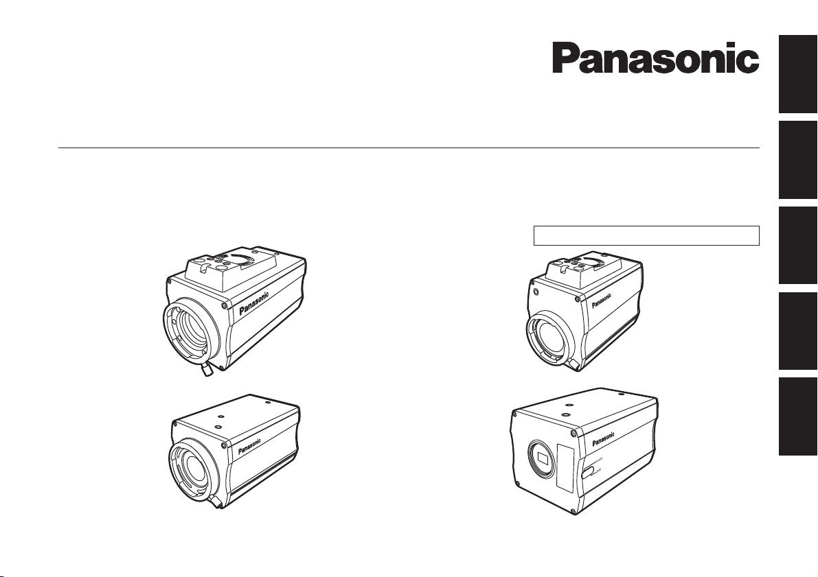
Convertible Camera
Model No. AW-E750E/E655E/E650E/E350E
Installation instructions provided
FRANÇAIS DEUTSCH ENGLISHITALIANOESPAÑOL
AW-E750E
AW-E650E
Before operating this product, please read the instructions carefully and save this manual for future use.
AW-E655E
AW-E350E
VQT0G72-6
ENGLISH VERSION
w DO NOT REMOVE PANEL COVERS BY
UNSCREWING.
To reduce the risk of electric shock, do not remove
the covers. No user serviceable parts inside.
Refer servicing to qualified service personnel.
WARNING:
TO REDUCE THE RISK OF FIRE OR SHOCK
HAZARD, KEEP THIS EQUIPMENT AWAY
FROM ALL LIQUIDS-USE AND STORE ONLY
IN LOCATIONS WHICH ARE NOT EXPOSED
TO THE RISK OF DRIPPING OR SPLASHING
LIQUIDS, AND DO NOT PLACE ANY LIQUID
CONTAINERS ON TOP OF THE EQUIPMENT.
indicates safety information.
- 1 (E) -
CAUTION:
TO REDUCE THE RISK OF FIRE OR SHOCK
HAZARD AND ANNOYING INTERFERENCE,
USE THE RECOMMENDED ACCESSORIES
ONLY.
Note:
The rating plate (serial number plate) is on the
bottom of the unit.

CONTENTS
Caution:
Before attempting to connect or operate this product,
please read these instructions completely.
The information marking of this product may be found on
the bottom of the product.
The serial number of this product may be found on the
bottom of the product.
You should note the serial number of this product in the
space provided and retain this book as a permanent
record of your purchase to aid identification in the event
of theft.
Model No.
Serial No.
PREFACE ..................................................................... 3
ENGLISH
STANDARD ACCESSORIES ....................................... 4
FEATURES ................................................................... 5
SPECIAL NOTES ON OPERATION ............................. 6
PRECAUTIONS ............................................................ 7
PRECAUTIONS FOR INSTALLATION ......................... 9
MAJOR OPERATING CONTROLS
AND THEIR FUNCTIONS ................................... 12
MOUNTING ................................................................ 17
FLANGE BACK
ADJUSTMENT (FOR ZOOM LENS) ................... 24
IRIS GAIN CONTROL IN A LENS .............................. 26
CONNECTIONS ......................................................... 27
ADJUSTMENT ........................................................... 32
USE MODE SETTING ................................................ 41
MENU ITEM SETTING ............................................... 43
SETTING AND CHANGING
THE OPTIONAL CARDS ..................................... 67
SETTING TO INITIAL SET ......................................... 69
APPEARANCE ........................................................... 73
SPECIFICATIONS ...................................................... 77
- 2 (E) -

PREFACE
• The Panasonic AW-E750, AW-E655, AW-E650 and
AW-E350 are digital signal processing colour video
cameras that incorporates three CCDs;
2/3˝ 3CCD (AW-E750)
1/2˝ 3CCD (AW-E655, AW-E650)
1/3˝ 3CCD (AW-E350)
A digital video signal processing system is packed in a
compact, lightweight body while assuring high picture
quality, high reliability and high performance.
• System setup and adjustments can be easily
performed by following the setup menu.
• Connection to peripheral devices, such as a RCU, a
ROP and a lens and the camera pan/tilt unit enables a
wide variation of system configurations.
• Option cards may also be installed.
K The following cards are not available for AW-E750,
AW-E655, AW-E650, AW-E350;
· AW-PB301 Component Studio Card:
Use AW-PB305A.
· AW-PB302 RGB Card: The camera unit
contains this function.
· AW-PB303 High-sensit ivity Card:
The camera unit
contains this function.
· AW-PB304 SDI Card: Use AW-PB504.
· AW-PB306 Studio SDI Card: Use AW-PB506 or
AW-PB506A.
· AW-PB307 SVGA card
· AW-PB309 WEB card
· AW-PB310 IEEE 1394 Card
Note
In order to protect the environment when the
convertible camera is to be discarded at the end
of its service life, ask a specialized contractor to
dispose of it properly.
- 3 (E) -

STANDARD ACCESSORIES
Operating Instructions ................................................. 1
Camera mounting adapter ........................................... 1
Mounting screws for adapter (M4) ............................... 2
<AW-E750/AW-E655>
Mounting screw for wire (Inch screw: 1/4-20UNC) ...... 1
Flat washer for wire (Inch screw) ................................. 1
Spring washer for wire (Inch screw) ............................ 1
<AW-E650/AW-E350>
Mo unting screw for wire (M4)
(with flat washer and spring washer) ...................... 1
Round Seal .................................................................. 2
ENGLISH
- 4 (E) -

FEATURES
1. Digital video signal processing for high quality, high
reliability, high performance, lightweight and compact
size.
2. Resolution: 850 lines (HIGH BAND DTL: ON)
S/N ratio:
65 dB (DNR ON) ( AW-E750, AW-E655,
AW-E650)
63 dB (DNR ON) (AW-E350)
3. Minimum illumination:
0.00005 lx ( AW-E750, AW-E655, AW-E650)
0.00015 lx (AW-E350)
4. The built-in CCD storage function and digital gain
up function provide an even higher degree of high
sensitivity.
5. RGB, Y/Pr/Pb and Y/C signal output circuits
provided.
6. Motorized filters containing IR through and ND filters
(1/16, 1/64) incorporated (model AW-E655 only).
7. Built-in automatic controls, including ATW, ELC, and
AGC.
8. CCD readout is switchable between field and frame
modes. Vertical resolution can be stepped up in
frame mode and it is effective for shooting still
objects.
9. The built-in synchronized scanning system reduces
noise in computer graphics.
10. Various correction circuits permit video reproduction
with high fidelity.
11. Chroma detail correction enables clear shots of dark
colour objects.
12. A dark detail circuit provides natural edge correction
to any object in a dark scene.
13. A digital colour matrix enables high fidelity colour
images.
14. The 12-axis digital colour matrix enables users’ to
create images of their choice.
15. Four use modes for each of your specific
applications can be selected.
16. Full colour bar is indicated on the monitor screen.
17. Remote control with a RCU, ROP or a multi hybrid
control panel.
- 5 (E) -

SPECIAL NOTES ON OPERATION
ENGLISH
• Turn power off before connecting or disconnecting
cables.
• Connection or disconnection of any studio cable,
RCU cable or other cable to any unit of equipment
must be performed while power is off.
• While the camera is in automatic mode;
Shooting of bright objects in ELC operation mode
may result in a smeared picture unique to the CCD.
The ATW function under fluorescent illumination can
adversely change the white balance.
• There is a cooling fan inside.
Do not cover the port or otherwise block ventilation
during operation. Internal heat buildup can cause a
fire.
It is an expendable part, and must be replaced about
every 30 000 hours. (Whenever fan replacement
is necessary, be sure to ask the store where you
purchased the set.) (AW-E750, AW-E655)
- 6 (E) -

PRECAUTIONS
DON’TS
• Do not attempt to disassemble the camera, Remote
Control Unit (RCU) or other units. In order to prevent
electric shock, do not remove screws or covers.
There are no user-serviceable parts inside.
• Do not abuse the camera. Avoid striking, shaking,
etc. The camera contains sensitive components
which could be damaged by improper handling or
storage.
• Do not let the lens remain uncapped when the
camera is not in use. If the lens is not installed,
do not leave the lens mount hole uncovered.
• Do not touch the surface of the lens or prism.
• Do not use strong of abrasive detergents when
cleaning the camera body.
• Do not aim the camera toward the sun, no matter
whether it is turned on or not.
• Do not expose the camera, Remote Control Unit
(RCU) or other units to rain or moisture, and do not
try to operate the equipment in wet conditions.
Do not operate the camera or RCU if it becomes wet.
• Do not operate the camera, Remote Control Unit
(RCU) or other units outdoors during a lightning
storm.
• Do not use the camera in an extreme environment
where high temperatures or high humidity exist.
• Do not leave the camera, Remote Control Unit
(RCU) or other units turned on when not in use.
Do not unnecessarily turn the camera power on and
off repeatedly. Do not block the ventilation slots.
• Do not cover the port otherwise block ventilation
during operation. Internal heat buildup can cause a
fire.
- 7 (E) -

DOS
• Refer any servicing to qualified service personnel.
• Handle the camera with care.
• Protect the precision made lens by placing the lens
cap over when the camera is not in use. If the lens
is not installed, protect the surface of the prism by
placing the body cap into the lens mount hole.
• Use a mild blower or lens cleaning tissue designed
for coated lenses, to clean the surface of the lens or
prism in the event that it should become dirty.
• Use a dry cloth to clean the camera if it is dirty. In
case the dirt is hard to remove, use mild detergent
and wipe gently.
• Use caution when operating the camera in the
vicinity of spot lights or bright lights, as well as light
reflecting objects and surfaces.
• Take immediate action if ever the camera or RCU
should become wet. Turn the power off and have the
unit checked by an authorized service facility.
• Follow normal safety precautions to avoid personal
injury.
• Use the camera in an environment where the
temperature is within –10 °C to +45 °C and the
relative humidity is within 30 % to 90 %.
• Always turn the power off when the camera is not
going to be used. Operate the camera and RCU only
when there is adequate ventilation.
ENGLISH
- 8 (E) -

PRECAUTIONS FOR INSTALLATION
Concerning the mounting screws and drop-prevention wire
The connection and installation should be done by
qualified service personnel or system installers.
Refer any servicing to qualified service personnel.
Attach the drop-prevention wire as a way to prevent
the camera from dropping.
p When the unit is to be mounted onto a Panasonic
pan-tilt head, use the mounting screws and dropprevention wire that are supplied with the pan-tilt head.
p When the unit is to be mounted onto a surface other
than a pan-tilt head, provide your own drop-prevention
wire and camera mounting bracket. For details of the
parts to be provided, refer to page 11.
p Attach the drop-prevention wire to the camera mounting
screw hole (Inch screw).
The camera cannot be installed or used in the
following locations.
p Outdoor locations and locations where the camera may
be exposed to dripping, splashing or sprayed water
p Locations such as swimming pools where chemicals are
used
p Locations such as a kitchen where the high levels of
steam and oily vapors are present and locations with
flammable atmospheres or other unusual conditions
p Locations where radioactive rays, X-rays or strong radio
waves or magnetic fields are generated
p Locations where the temperature may be outside the
camera’s operating ambient temperature (–10 °C to
45 °C) range
p Locations near the air outlet of an air conditioner or near
a door where the camera will be exposed to incoming
outside air or other locations where the temperature is
subject to sudden change (since these locations may
cause the lens area to cloud over and/or condensation
to form)
p Locations that are subject to significant vibration, such
as on top of a car
p Locations with high levels of humidity or dust
When the camera is not going to be used, do not leave
it in place but be absolutely sure to remove it from its
mounting, and put it away.
Do not run the camera cable near the wiring of electric
lights.
This may result in noise interference.
Concerning electromagnetic interference
The camera’s images may become distorted or noise
interference may result if the camera is used near a TV
or radio transmission antenna or in strong electrical or
magnetic fields (such as one generated by motors,
transformers, etc.).
Using outdoors
The camera is designed to be used indoors.
When using outdoors, be absolutely sure to use the
AW-PH650 outdoor pan-tilt head.
- 9 (E) -
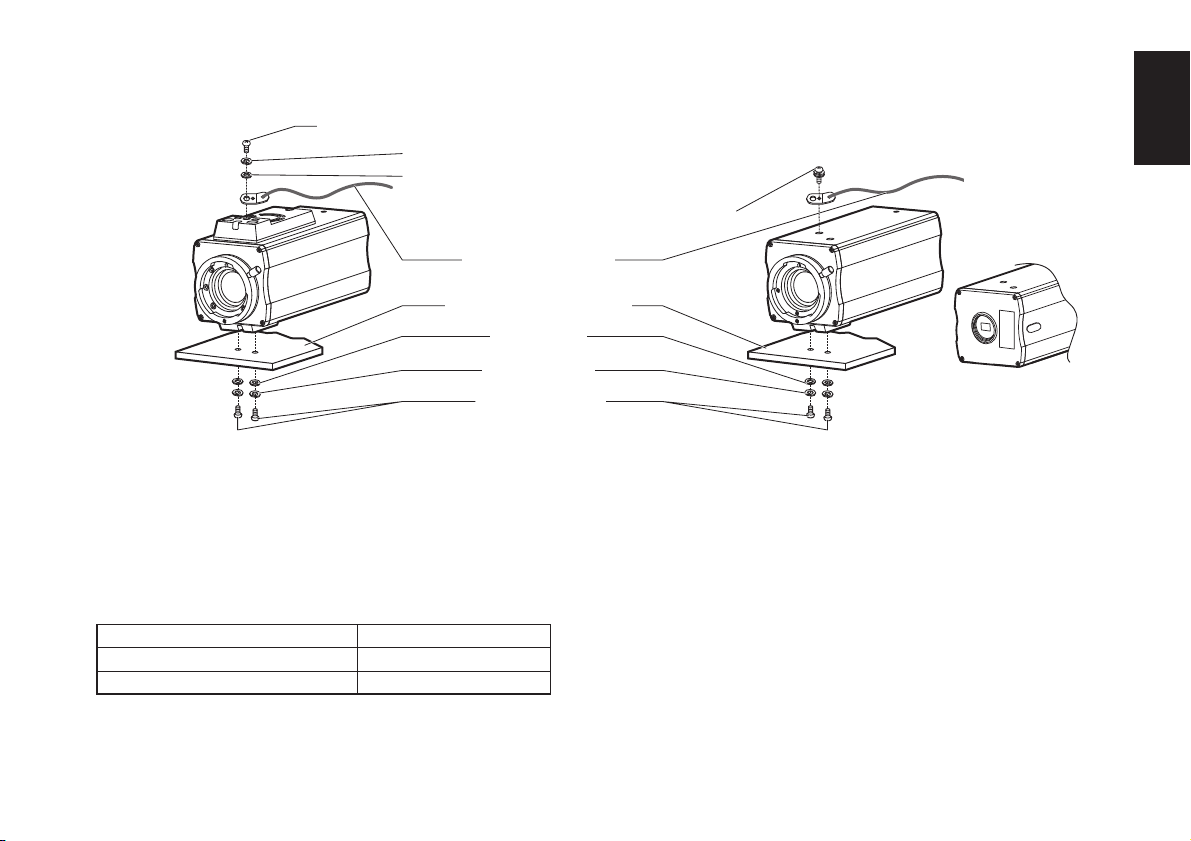
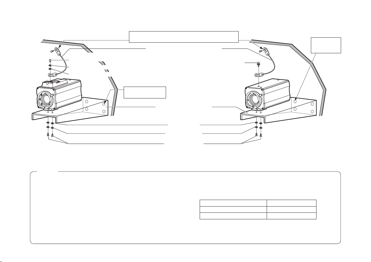
<AW-E750/AW-E655> <AW-E650/AW-E350>
Mounting screw for wire (supplied) (Inch screw: 1/4-20UNC)
Spring washer (supplied)
Flat washer (supplied)
Drop-prevention wire
Pan-tilt head or
camera mounting bracket
Flat washers
Spring washers
Mounting screws
(Inch screws: 1/4-20UNC)
Tightening the mounting screws
Tighten using the torque levels shown in the table below.
After tightening, check for play and unsteadiness.
Screws Clamping torque
Mounting screws (M4) 1.5 N • m (15 kgf • cm)
Mounting screws (Inch screws) 2.0 N • m (20 kgf • cm)
ENGLISH
(AW-E650)
Mounting screw for wire
(supplied) (M4)
(AW-E350)
- 10 (E) -
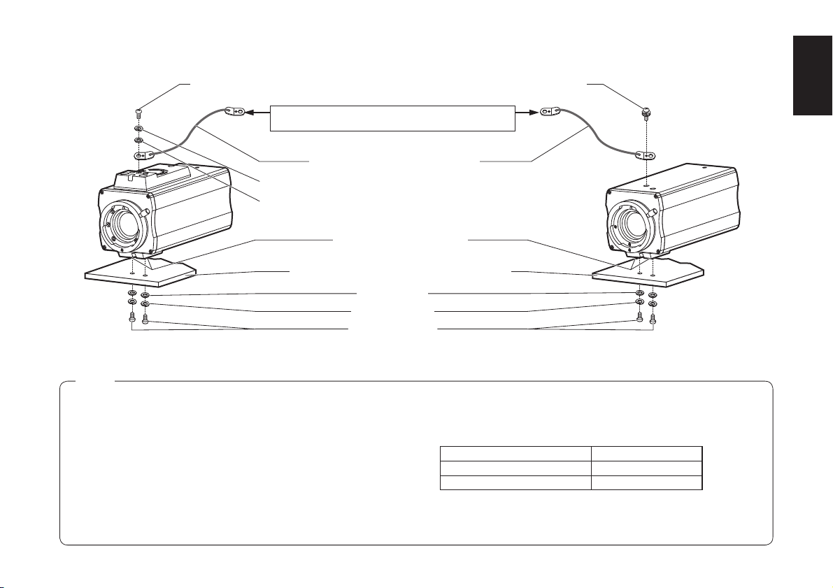
Parts to be provided by the customer for installation
When the unit is to be mounted onto a Panasonic pan-tilt
head, use the mounting screws and drop-prevention wire
that are supplied with the pan-tilt head.
Provide the following parts when the unit is to be mounted
onto a surface other than a pan-tilt head.
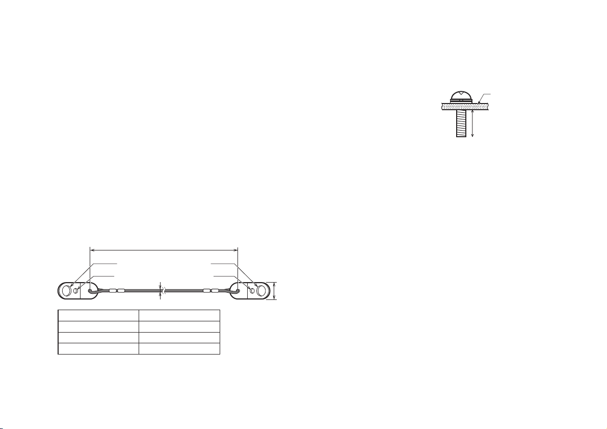
Drop-prevention wire* (sold separately): 1
(*Be absolutely sure to use the drop-prevention wire.)
Drop-prevention wires in three different lengths (300 mm,
450 mm and 600 mm) are available as optional
accessories.
Use a wire in the length that will have no slack to suit the
installation location and installation method.
Consult your dealer when you purchase one of these
drop-prevention wires.
Wire length (300, 450 or 600 mm)
( Camera
side)
Wire length (mm) Parts number
ø6.5
ø4.2
300 3CN001064BAA
450 3CN001064BAB
600 3CN001064BAC
ø1.2
ø6.5
ø4.2
( Installation
side)
11 mm
Mounting screws (Inch screws: 1/4-20UNC): 2
(For mounting the camera)
Determine the length
of these screws by
Camera
mounting bracket
factoring in the thickness
of the camera mounting
7 to 9 mm
bracket.
Mounting screws (M6) for installation end wire
At the installation location, be absolutely sure to use
the anchor bolts, and ensure that the strength of the
installation surface is at least ten times the total mass of
all units installed.
Flat washers for use with 1/4˝ screws: 2
(For mounting the camera)
Spring washers for use with 1/4˝ screws: 2
(For mounting the camera)
Camera mounting bracket: 1
Use a bracket made of a material and having a shape
that is strong enough to support the total mass of all units
installed, including the camera and lens.
To determine the position of the holes used for mounting
the camera, refer to <Bottom view> on page 12, and
make holes with a diameter of 7 mm (to support 1/420UNC mounting screws).
- 11 (E) -
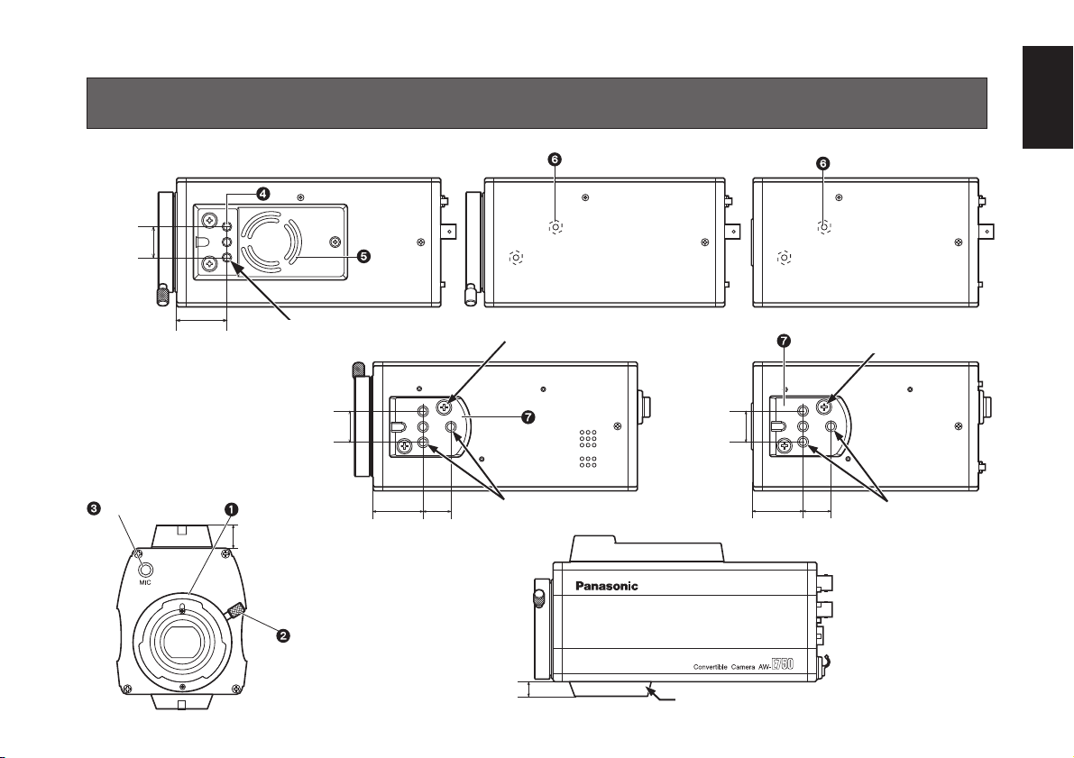
MAJOR OPERATING CONTROLS AND THEIR FUNCTIONS
<Top View>
20 mm
(AW-E650)(AW-E750/AW-E655)
(AW-E350)
ENGLISH
32.5 mm
<Bottom View>
<Front View>
(AW-E655 only)
Mounting screws (Inch screws)
1/4-20UNC, Depth: 10 mm
20 mm
32.5 mm
17.5 mm
Use the adapter mounting screws
(M4, supplied) for mounting.
18 mm
Mounting screws (Inch screws)
1/4-20UNC, Depth: 10 mm
<Side View>
10 mm
- 12 (E) -
Use the adapter mounting screws
(M4, supplied) for mounting.
(AW-E350)(AW-E750/AW-E655/AW-E650)
20 mm
32.5 mm
18 mm
Supplied part (installed on-site)
Mounting screws
(Inch screws)
1/4-20UNC,
Depth: 10 mm

Lens mount
2/3˝ Standard bayonet type (B4 mount) lens
(AW-E750)
1/2˝ Standard bayonet type (B4 mount) lens
(AW-E655, AW-E650)
1/3˝ C mount lens (AW-E350)
One of the lenses listed above or a microscope adapter
is installed on this mount.
Mounting hole (AW-E750, AW-E655 only)
To install the camera on a wall or ceiling or to use a
pan/tilt head or tripod, secure the unit using this screw
hole (1/4-20UNC) or using the accessory mounting
adapter.
Furthermore, attach the drop-prevention wire into these
screw holes, using the mounting screws for wire (Inch
screw: 1/4-20UNC).
Lens fixing ring knob
(AW-E750/AW-E655/AW-E650 only)
Rotate the lens fixing ring knob counterclockwise and
remove the lens mount cap. Mount the lens on the
camera and rotate the lens fixing ring knob clockwise in
order to fix the lens securely.
Mic jack (AW-E655 only)
This is a ø3.5 mm mic jack which supports PLUG IN
POWER. Use the microphone which has more than 1kj
of impedance, unbalanced.
Cooling fan (AW-E750, AW-E655 only)
The cooling fan can be set to “Auto” or “OFF” on the
menu.
Wire mounting hole (AW-E650/AW-E350 only)
When mounting the camera using the bottom panel,
attach the drop-prevention wire to this hole using the
mounting screw for wire (M4) that is supplied.
Camera mounting adapter
When mounting the camera onto an on-site mounting
bracket, pan-tilt head, or tripod, install this adapter onto
the bottom panel of the camera. This is a part that is
supplied so refer to page 19 for its installation.
- 13 (E) -
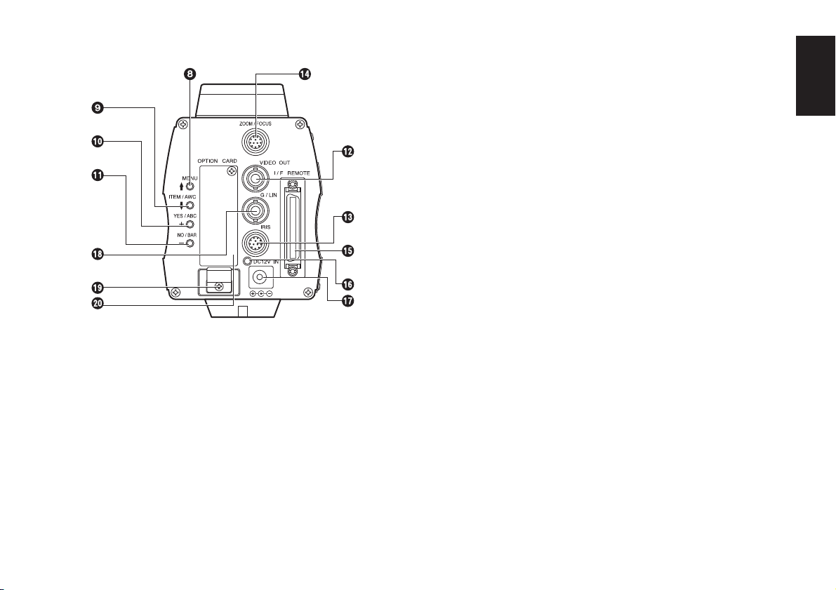
<Rear View>
MENU switch (MENU/©)
A menu will appear on the monitor screen when this
switch is pressed for about 5 seconds. This item can be
selected by pressing the switch while the menu is on the
screen.
ITEM/AWC switch (ITEM/AWC/ª)
The item just below can be selected by pressing this
switch while the menu is on the screen. When the menu
is not displayed or the camera is in shooting mode, the
automatic white balance control can be set with this
switch.
YES/ABC switch (YES/ABC/+)
The Sub Menu for each item of the Main Menu is
displayed when this switch is pressed while the Main
Menu is on the screen.
While the Sub Menu is displayed, any setting can be
brought up to a higher value with this switch.
When the menu is not displayed or the camera is in
shooting mode, the automatic black balance control can
be set with this switch.
NO/BAR Switch (NO/BAR/–)
The item just below can be selected by pressing this
switch while the Sub Menu is on the screen.
While the Sub Menu is displayed any setting can be
brought down to a lower value with this switch.
When the menu is not displayed or the camera is
in shooting mode, the colour bar and the shooting
conditions are indicated by pressing the switch.
Video output connector (VIDEO OUT)
A composite video signal is provided at this connector.
ENGLISH
- 14 (E) -
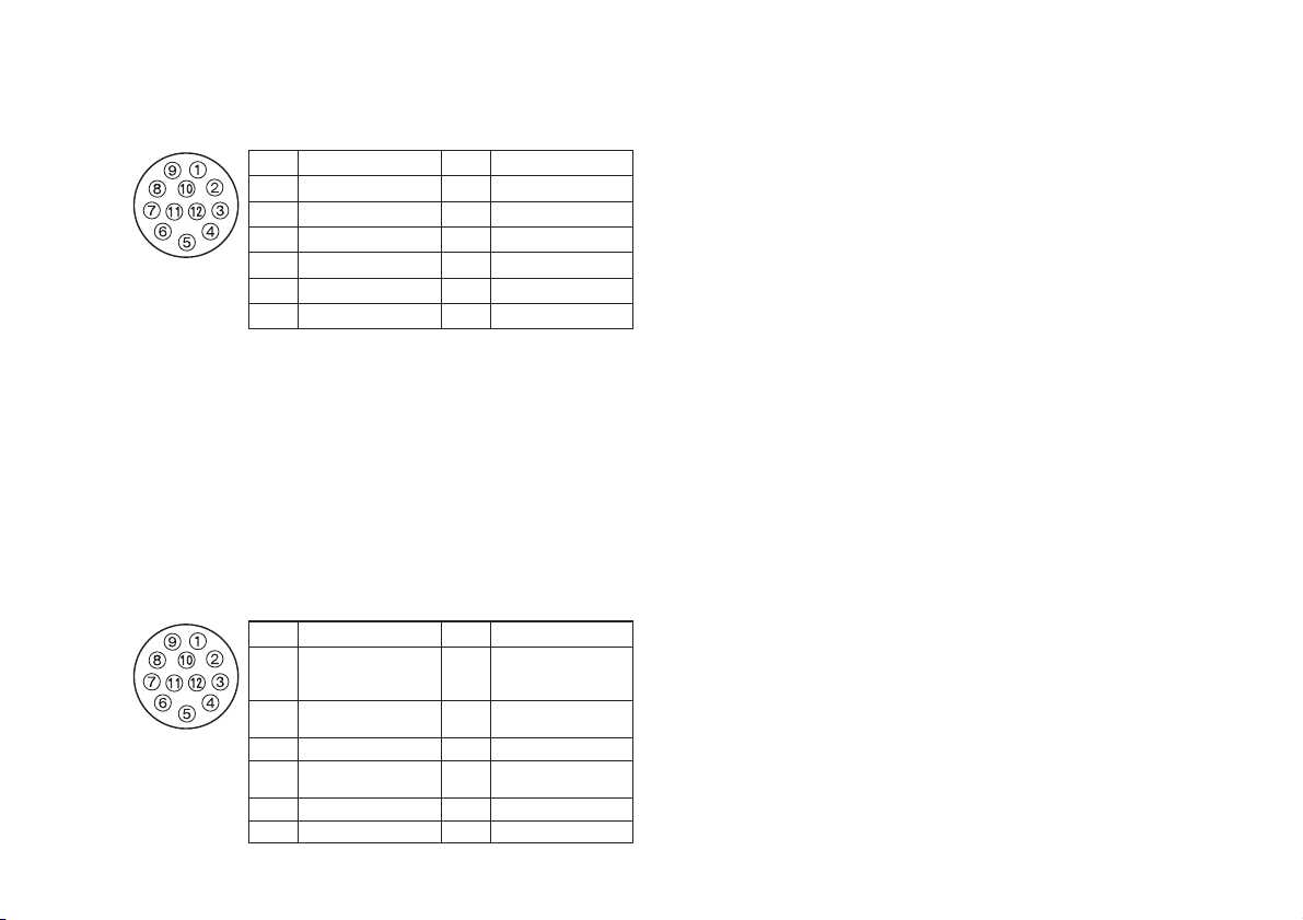
Iris connector (IRIS)
Input terminal for lens with an iris control function.
Pin No.
1 Return Control 7 Iris Follow
2 Not Used 8
3 GND 9 Not Used
4 Auto/Manual Control 10 Not Used
5 Iris Control 11 Not Used
6 Lens Power 12 Not Used
Signal
Pin No.
Auto/Remote Control
Signal
Zoom/Focus connector (ZOOM/FOCUS)
(AW-E655 only)
This connector is for the remote cable of the lens and
is a standard input connector for lenses with remote
functions for zooming and focusing.
When the camera is to be mounted on a Panasonic
pan/tilt head (such as the AW-PH360/AW-PH400/
AW-PH405/AW-PH650), do not use this connector —
connect the remote cable of the lens to the LENS I/F
connector on the pan/tilt head instead.
Pin No.
1
2
3 GND 9 Zoom Control
4
5 Iris Control 11 +V (+7.5 V)
6 Lens Power 12 –V (+2.5 V)
Signal
Focus Mode
Position/Speed/
Auto Focus
Zoom Mode
Position/Speed
Iris
Remote/Camera
Pin No.
7
8 Focus Control
10
Signal
Signal Control
(+5.0 V)
Iris Mode
Position/Speed
I/F remote connector (I/F REMOTE)
Input terminal dedicated to control signals from the
optional Remote Operation Panel (ROP) (such as the
AW-CB400) and the RCU (such as the
AW-RC600) and the camera pan/tilt unit (such as the
AW-PH360/AW-PH400/AW-PH405/AW-PH650).
• AW-CB400 is connected through the optional
connecting cable (AW-CA50T8).
• AW-RC600 is connected through the optional RCU
cable (AW-CA50A26).
• Use the cable supplied with the pan/tilt head to connect
the AW-PH360, AW-PH400, AW-PH405 or AW-PH650.
Power indicator
Red LED lamp lights to indicate that the specified DC
power is supplied to the camera.
- 15 (E) -
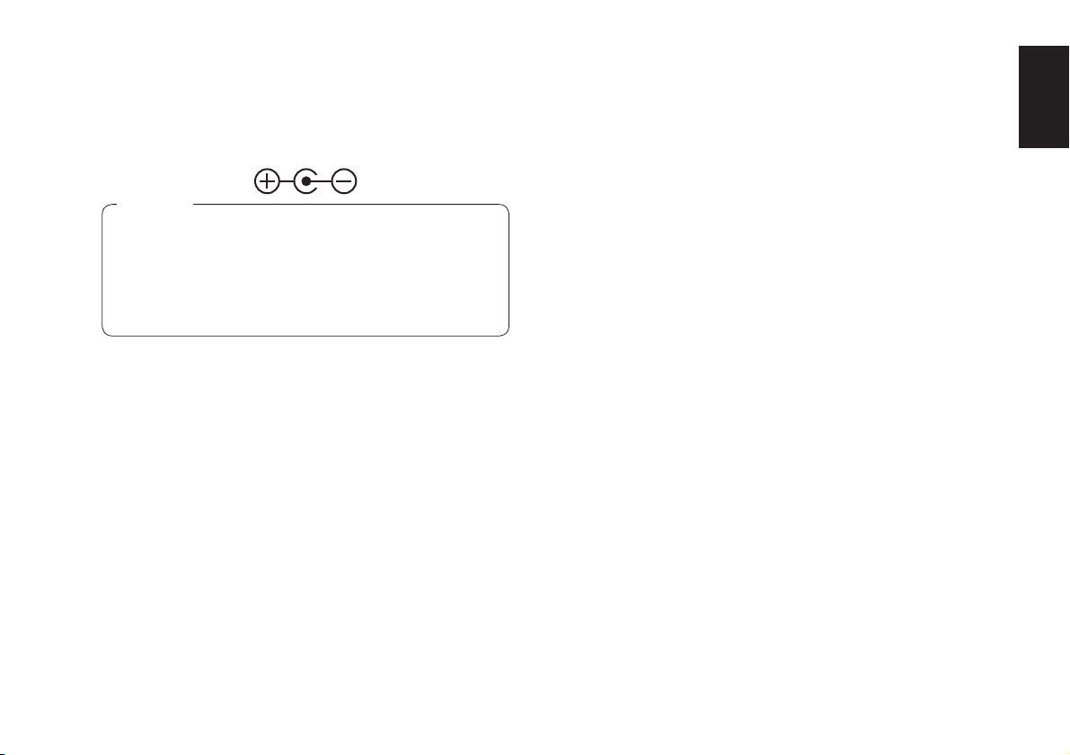
DC 12 V input connector (DC 12V IN)
12 V DC is supplied through the DC cable with ø6.5
plug. (Supplied with the recommended AC adapter:
AW-PS505A)
Cautions
1. Connect this to a DC 12 V class 2 power supply
only.
2. To prevent fire or shock, the UL listed wire
VW-1, style 1007 should be used as for the cable
for DC 12 V Input Connector.
G/L input connector (G/L IN)
Signals synchronized with the reference signal are to
be supplied to this connector when the camera is to be
synchronized with the reference signal BB.
Cable clamp
Clamp the DC cable with ø6.5 plug connected to the DC
12 V input connector to prevent it from slipping out.
Optional card slot
Slot for inserting an optional card. For details, refer to
the manual for optional cards.
ENGLISH
- 16 (E) -
MOUNTING
The connection and installation should be done by
qualified service personnel or system installers.
Refer any servicing to qualified service personnel.
w Lens mounting
AW-E750, AW-E655, AW-E650
(Bayonet mount type of lens)
• Use the lens extension cable AW-CA12T12A (6˝/15 cm)
if your lens cable is too short.
Rotate the lens fixing ring knob counterclockwise and
remove the lens mount cap.
Mount the lens on the camera and rotate the lens
fixing ring knob clockwise in order to fix the lens
securely.
Connect the camera cable to the IRIS connector on
the back panel of the camera.
Control Cable
Camera Cable
(AW-E750, AW-E650, AW-E350)
To Lens I/F Connector of
Camera Pan/tilt Unit
Lens fixing
ring knob
To Iris
Connector
(model AW-E655 only)
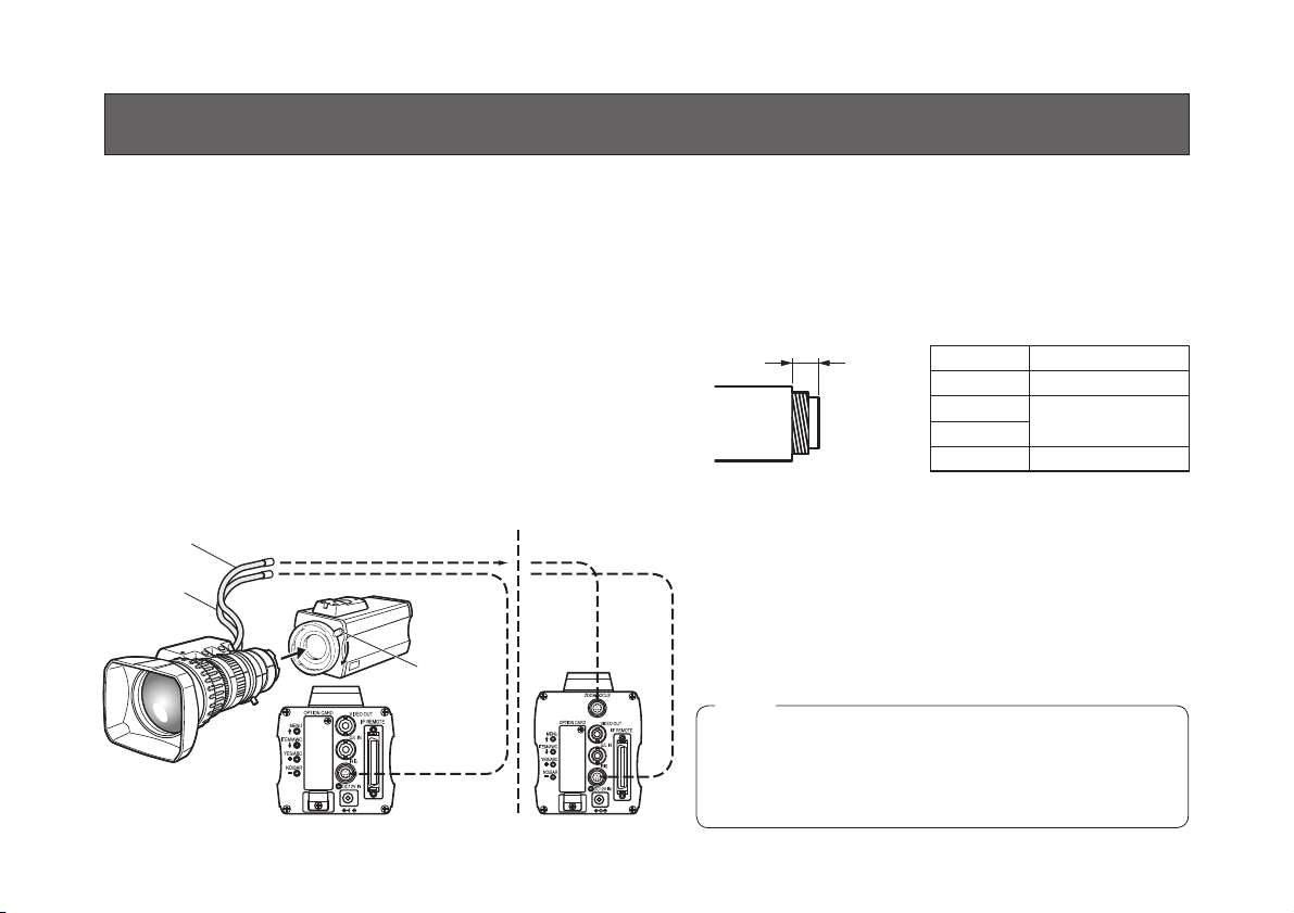
AW-E350 (C mount type of lens)
• A 1/3-inch C mount type of lens can be used.
Be absolutely sure that a lens whose mount threads
extend no more than 4.3 mm from the lens mount
surface is used. Use of any other kind of lens may
damage the camera unit.
Less than 4.3 mm
<Recommended lenses>
Camera Lens
AW-E350 AW-LZ16MD55P
AW-E650
AW-E655
AW-E750 AW-LZ17MD9AG
AW-LZ16MD73P
• Some lenses need to be attached in a different way.
Therefore, reference should also be made to the
operating instructions that accompany the lens.
Remove the lens mount cap, align the lens with
the thread ridges on the lens mount and screw it
securely into place.
Connect the lens cable to the IRIS connector.
Note
p Tighten the lens mount lock ring securely to secure
the lens, and check that there is no unsteadiness in
the lens. Also check that there is no unsteadiness
in the hood.
- 17 (E) -
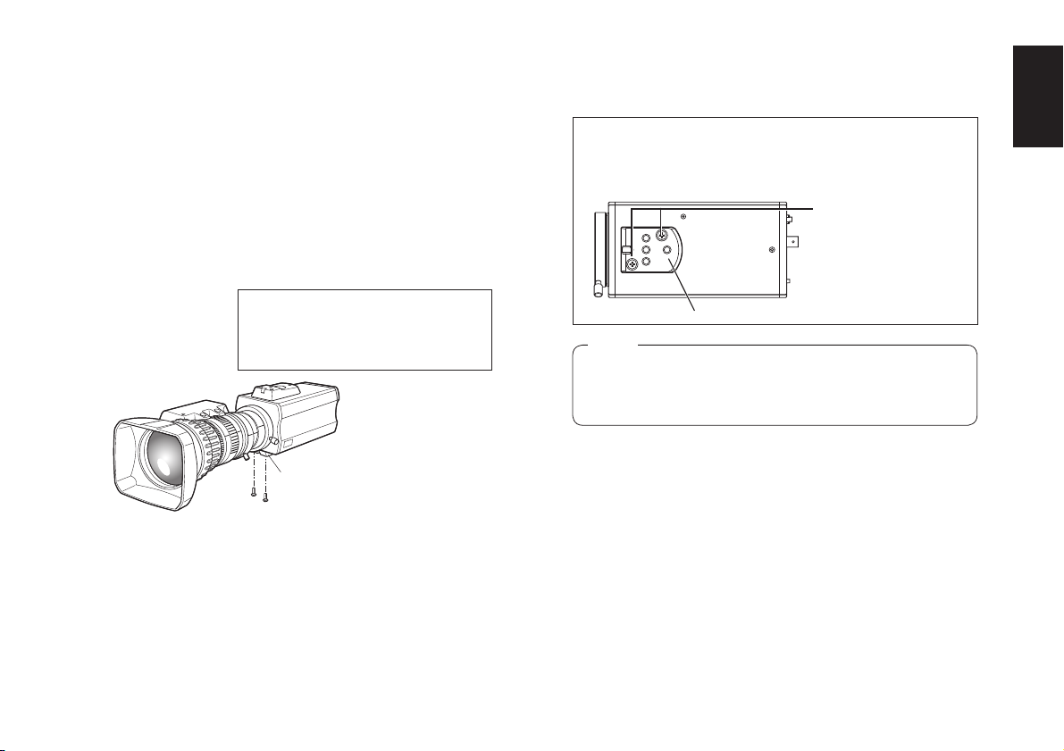
w Mounting the camera onto a camera mounting base (pan-tilt head or tripod)
AW-E750 or AW-E655 models:
Use the screws provided to attach the accessory
camera mounting adapter to the bottom panel of the
camera.
AW-E650 or AW-E350 models:
Use the screws provided to attach the accessory
camera mounting adapter to the top or bottom panel
of the camera.
For use in a very bright location, paste
the supplied round seal on the hole
not used by the camera mounting
adapter.
Camera mounting
adapter
Use a screwdriver or similar to tighten the screws to
secure the camera mounting adapter.
Make sure that the camera mounting adapter is attached
the right way round.
Mounting screws for
adapter (supplied)
Camer mounting adapter (supplied)
Note
p Install the camera mounting adapter by tightening
it securely with a torque of 1.5 N • m (15 kgf • cm),
and check that there is no unsteadiness.
Fix the camera mounting base, pan/tilt unit, and
tripod securely in the camera mounting screw hole
(Inch screw: 1/4-20UNC) of the attached camera
mounting adapter.
ENGLISH
- 18 (E) -
w Mounting the camera onto a pan-tilt head, tripod, camera mounting bracket, or other part
Use the camera mounting screw holes (Inch screw:
1/4-20UNC) to mount onto a pan-tilt head, tripod,
camera mounting bracket, or other part.
[AW-E750/AW-E655]
Attach the drop-prevention wire using the mounting
screw (Inch screw: 1/4-20UNC) into the camera
mounting screw holes on the camera’s top surface
when mounting the camera with its bottom surface,
or on the camera’s bottom surface when mounting
the camera with its top surface.
[AW-E650/AW-E350]
Attach the drop-prevention wire using the mounting
screw (M4) into the mounting screw hole for camera
mounting adapter on the camera’s top surface when
mounting the camera with its bottom surface, or on
the camera’s bottom surface when mounting the
camera with its top surface.
When the unit is to be mounted onto a Panasonic
pan-tilt head, use the mounting screws and dropprevention wire that are supplied with the pan-tilt
head.
When the unit is to be mounted onto a tripod,
camera mounting bracket, or other part, refer to
pages 9 to 11, and provide your own drop-prevention
wire, mounting screws, and washers.
Camera mounting screw holes
(Inch screws: 1/4-20UNC)
Depth: 10 mm
Camera mounting adapter
Notes
Preventing the camera from falling or coming off
p When attaching a camera to the pan/tilt head
(AW-PH360/AW-PH400/AW-PH405/AW-PH650),
follow the directions in the Operating Instructions to
fix the camera firmly in position.
In addition, link the camera to the pan/tilt head
using the drop-prevention wire and the mounting
screws to help ensure the camera does not fall.
p When attaching the camera on any mounting or
other pan/tilt head (AW-PH360/AW-PH400/
AW-PH405/AW-PH650), check that the mounting
can safely bear the total mass of the camera,
lens, connection cables, etc., fix the camera firmly
in position using the prescribed tool, and take
appropriate measures to prevent the camera from
falling.
- 19 (E) -
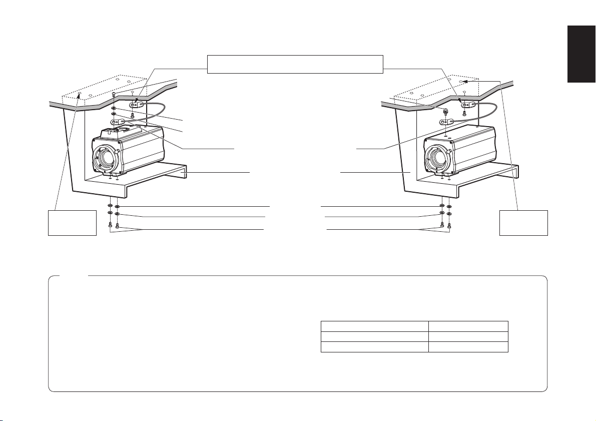
p Example where the camera is mounted on a ceiling or wall
Secure the end of the wire onto the M6 anchor bolts by
(Ceiling)
tightening nut or secure it by tightening the M6 bolts.
Mounting screw for wire (supplied)
(Inch screw: 1/4-20UNC)
Spring washer (supplied)
Flat washer (supplied)
Drop-prevention wire (sold separately)
Camera mounting bracket [*]
Mounting screw for wire (M4)
(supplied)
ENGLISH
Always mount
using the
anchor bolt.
AW-E750/AW-E655
Spring washers [*]
Mounting screws [*]
(Inch screws: 1/4-20UNC)
[*]: Procured locally
Notes
p When installing the mounting bracket or attaching one
end of the drop-prevention wire to the ceiling or a wall, be
absolutely sure to use the anchor bolts, and ensure that
the withdrawal strength of the installation surface is at least
ten times the total mass of all units installed, including the
mounting bracket, camera, lens, and cables.
p Ensure that the total mass, including the mounting bracket,
camera, lens and cables, does not exceed 8 kg.
p Ensure that a drop-prevention wire is installed in such a
way that the drop distance does not exceed 150 mm.
Flat washers [*]
- 20 (E) -
Always mount
using the
anchor bolt.
AW-E650/AW-E350
( The mounting method shown in the illustration
above is for the AW-E650 and AW-E350.
The same method is used for both models.)
p Tighten the mounting screws using the torque levels
shown in the table to the below, and then check for play
and unsteadiness.
Screws Clamping torque
Mounting screws (M4) 1.5 N • m (15 kgf • cm)
Mounting screws (Inch screws) 2.0 N • m (20 kgf • cm)
p Do not use an impact driver as doing so may cause
damage to the screws.
(Wall)
Mounting screw for wire (supplied)
(Inch screw: 1/4-20UNC)
Spring washer (supplied)
Flat washer (supplied)
AW-E750/AW-E655
Secure the end of the wire onto the M6 anchor bolts by
tightening nut or secure it by tightening the M6 bolts.
Drop-prevention wire (sold separately)
Always mount using
the anchor bolt.
Camera mounting bracket [*]
Flat washers [*]
Spring washers [*]
Mounting screws [*]
(Inch screws: 1/4-20UNC)
[*]: Procured locally
Notes
p When installing the mounting bracket or attaching one
end of the drop-prevention wire to the ceiling or a wall, be
absolutely sure to use the anchor bolts, and ensure that
the withdrawal strength of the installation surface is at least
ten times the total mass of all units installed, including the
mounting bracket, camera, lens, and cables.
p Ensure that the total mass, including the mounting bracket,
camera, lens and cables, does not exceed 8 kg.
p Ensure that a drop-prevention wire is installed in such a
way that the drop distance does not exceed 150 mm.
Mounting screw for wire (M4)
(supplied)
AW-E650/AW-E350
( The mounting method shown in the illustration
above is for the AW-E650 and AW-E350.
The same method is used for both models.)
p Tighten the mounting screws using the torque levels
shown in the table to the below, and then check for play
and unsteadiness.
Screws Clamping torque
Mounting screws (M4) 1.5 N • m (15 kgf • cm)
Mounting screws (Inch screws) 2.0 N • m (20 kgf • cm)
p Do not use an impact driver as doing so may cause
damage to the screws.
Always mount
using the
anchor bolt.
- 21 (E) -
p Example of mounting the camera onto a bracket or tripod made by another manufacturer
Mounting screw for wire (supplied)
(Inch screw: 1/4-20UNC)
Secure the end of the wire onto the M6 anchor bolts by
tightening nut or secure it by tightening the M6 bolts.
Drop-prevention wire (sold separately)
Spring washer (supplied)
Flat washer (supplied)
Camera mounting screw holes
Bracket or tripod made by another manufacturer [*]
Flat washers [*]
Spring washers [*]
Mounting screws [*]
AW-E750/AW-E655
(Inch screws: 1/4-20UNC)
[*]: Procured locally
Notes
p When installing the mounting bracket or attaching one end of the
drop-prevention wire to the ceiling or a wall, be absolutely sure to
use the anchor bolts, and ensure that the withdrawal strength of the
installation surface is at least ten times the total mass of all units
installed, including the mounting bracket, camera, lens, and cables.
p When the camera has been attached to a tripod as well, be absolutely
sure to prevent the camera from falling off by using the screw in the
tripod or other such means.
p When mounting the camera on a surface above the camera, do not
block the ventilation holes of the cooling fan.
p Ensure that the total mass, including the mounting bracket, camera,
lens and cables, does not exceed 8 kg.
Mounting screw for wire (M4) (supplied)
AW-E650/AW-E350
( The mounting method shown in the illustration
above is for the AW-E650 and AW-E350.
The same method is used for both models.)
p Ensure that a drop-prevention wire is installed in such a way that the
drop distance does not exceed 150 mm.
p Tighten the mounting screws using the torque levels shown in the
table to the below, and then check for play and unsteadiness.
Screws Clamping torque
Mounting screws (M4) 1.5 N • m (15 kgf • cm)
Mounting screws (Inch screws) 2.0 N • m (20 kgf • cm)
p Do not use an impact driver as doing so may cause damage to the
screws.
- 22 (E) -
ENGLISH
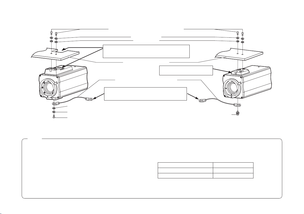
p Example of mounting on a surface above the camera
Mounting screws [*] (Inch screws: 1/4-20UNC)
Spring washers [*]
Flat washers [*]
Adjust the camera mounting bracket on the surface
above the camera so that the ventilation holes of the
cooling fan will not be blocked.
Camera mounting bracket [*]
Drop-prevention wire (sold separately)
Secure the end of the wire onto the M6 anchor
bolts by tightening nut or secure it by tightening the
M6 bolts.
Flat washer (supplied)
Spring washer (supplied)
Mounting screw for wire (Inch screw: 1/4-20UNC) (supplied)
AW-E750/AW-E655
[*]: Procured locally
Notes
p When installing the mounting bracket or attaching one end of the
drop-prevention wire to the ceiling or a wall, be absolutely sure to
use the anchor bolts, and ensure that the withdrawal strength of the
installation surface is at least ten times the total mass of all units
installed, including the mounting bracket, camera, lens, and cables.
p When the camera has been attached to a tripod as well, be absolutely
sure to prevent the camera from falling off by using the screw in the
tripod or other such means.
p When mounting the camera on a surface above the camera, do not
block the ventilation holes of the cooling fan.
p Ensure that the total mass, including the mounting bracket, camera,
lens and cables, does not exceed 8 kg.
- 23 (E) -
Attach the camera mounting
adapter to the unit’s top surface.
Mounting screw for wire (M4) (supplied)
AW-E650/AW-E350
( The mounting method shown in the illustration
above is for the AW-E650 and AW-E350.
The same method is used for both models.)
p Ensure that a drop-prevention wire is installed in such a way that the
drop distance does not exceed 150 mm.
p Tighten the mounting screws using the torque levels shown in the
table to the below, and then check for play and unsteadiness.
Screws Clamping torque
Mounting screws (M4) 1.5 N • m (15 kgf • cm)
Mounting screws (Inch screws) 2.0 N • m (20 kgf • cm)
p Do not use an impact driver as doing so may cause damage to the
screws.
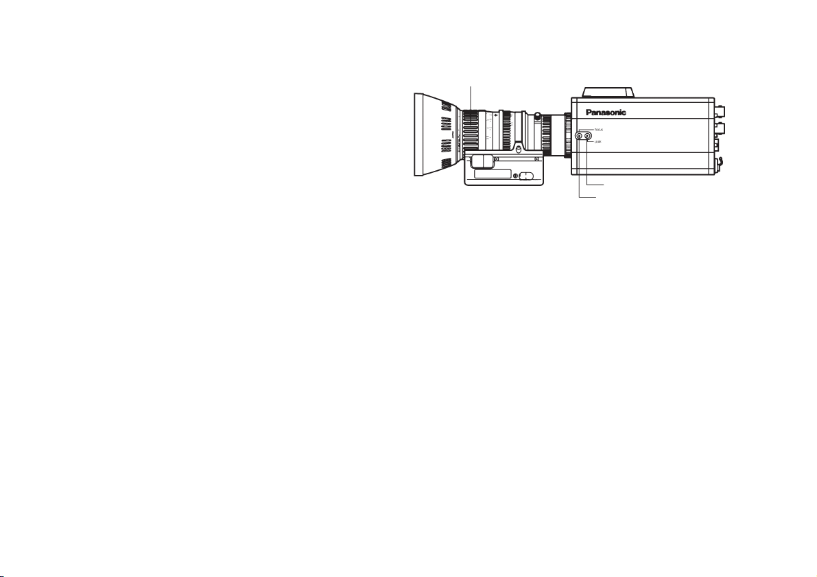
FLANGE BACK ADJUSTMENT (FOR ZOOM LENS)
ENGLISH
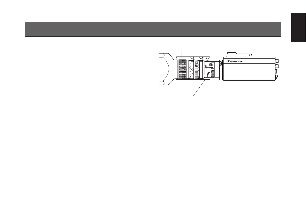
AW-E750, AW-E655, AW-E650
This adjustment will bring the subject into focus across
the whole range from the maximum telephoto position to
the widest angle position of the zoom lens.
1. Fully open the iris by shooting a dark object. (Iris
selection switch should be set to M.)
2. Loosen the flange back lock knob.
3. Aim the camera at any object over 2 meters away
from the camera.
4. Set the lens to its TELE end first and adjust its focus
with the focus ring.
5. Set the lens to its widest angle next and adjust its
focus with the flange back adjust ring.
6. Adjust the focus ring and the flange back adjust ring
alternately for the best focus within the zooming
range.
Tighten the flange back lock knob upon completion
of focusing.
7. Turn the iris selection switch to Position A.
FOCUS Ring Flange back adjust ring
Flange back lock knob
AW-E750, AW-E655, AW-E650
- 24 (E) -
AW-E350
This adjustment will bring the subject into focus across
the whole range from the maximum telephoto position to
the widest angle position of the zoom lens.
Perform this adjustment when back focusing is not
achieved with a fixed focus lens.
(Adjustment range: ±0.2 mm)
1. Fully open the iris by shooting a dark object.
2. Aim the camera at any object over 2 meters away
from the camera, remove the cap over the camera’s
flange back adjust screw, and loosen the LOCK
screw.
3. Set the lens to its TELE end first and adjust its focus
with the focus ring.
4. Set the lens to its widest angle next and turn the
FOCUS screw to adjust its focus.
5. Adjust the focus ring and FOCUS screw alternately
for the best focus within the the zooming range.
Tighten the LOCK screw upon completion of the
focusing.
FOCUS Ring
LOCK knob
FOCUS knob
AW-E350
- 25 (E) -
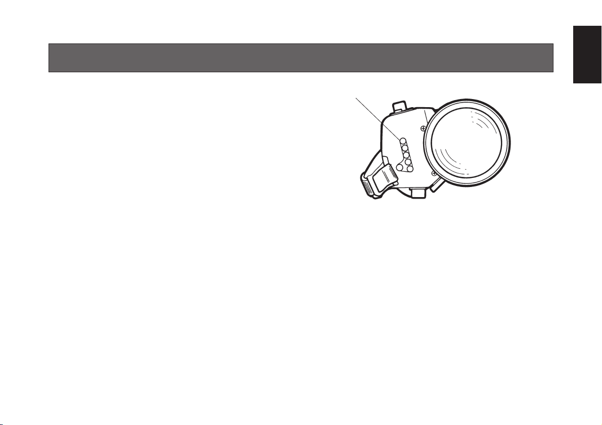
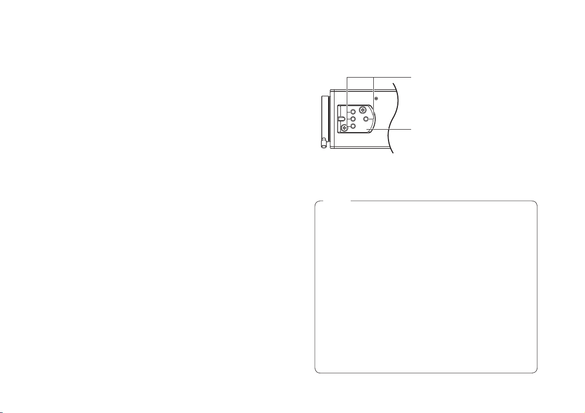
IRIS GAIN CONTROL IN A LENS
ENGLISH
An iris gain control hole is usually provided in the front of
the lens. Adjustment of the iris gain, with a screwdriver
through the hole may be done as follows. (Shape and
location of the hole may vary depending on the type of
lens.)
1. Turn the iris selection switch to Position A (AUTO).
2. Rotate the iris gain control to the maximum gain, but
in a range where no hunting or oscillating of the iris
ring develops.
Iris gain control (G, S)
Automatic iris power zoom lens
- 26 (E) -
CONNECTIONS
Caution:
The connection and installation should be done by qualified service personnel or system installers.
Refer any servicing to qualified service personnel.
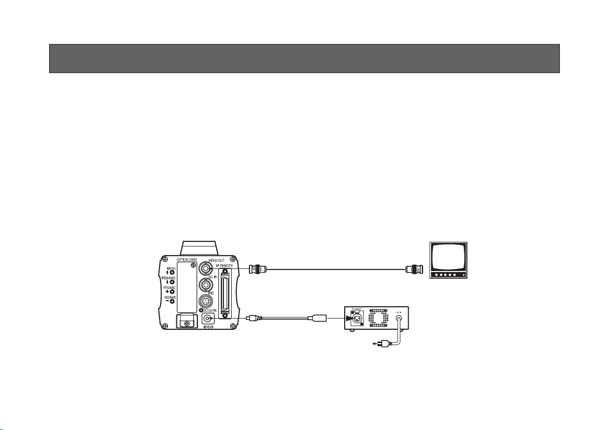
wCONNECTION OF DEVICE WITH A COMPOSITE INPUT CONNECTOR
• Connection to any device which has a composite input connector, such as a video monitor or a VTR, must be made
through the VIDEO OUT Connector.
• Power supply to the camera must be through the DC cable with ø6.5 plug supplied with AW-PS505A.
• For DC power supply, use the optional AC adapter AW-PS505A.
VIDEO OUT
connector
DC cable with
ø6.5 plug
(supplied with
AW-PS505A)
- 27 (E) -
75 j coaxial cable
VIDEO IN
Video monitor
AC Adapter
AW-PS505A
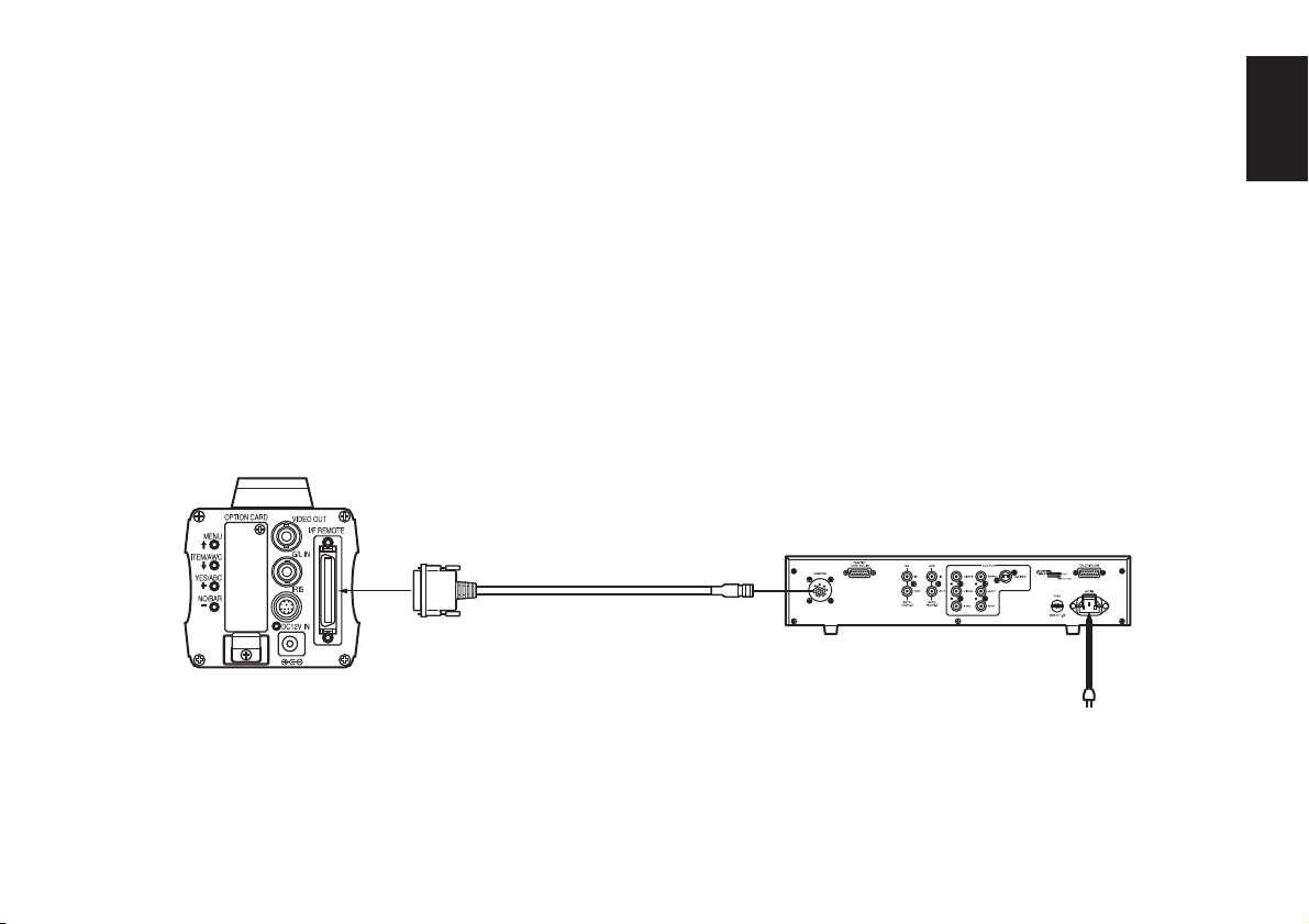
w CONNECTION OF A REMOTE CONTROL UNIT (RCU)
Connection to the RCU (AW-RC600) is made through
the optional RCU cable AW-CA50A26.
1. Turn RCU power off before connecting cables.
2. Connect the 50-pin connector of the RCU cable to
the I/F REMOTE Connector of the camera.
3. Turn RCU power on and the power indicator lamp
will light. The camera can now be remote controlled
by the RCU.
RCU Cable
AW-CA50A26 (15 m)
Notes:
• The maximum extension distance between the
camera and AW-RC600 is 100 m.
• Use the following options for cable extension.
Studio Cable WV-CA26U15 (15 m/50 ft)
WV-CA26U30 (30 m/100 ft)
WV-CA26U100 (100 m/330 ft)
Cable Joint Adapter
WV-CA26T26
AW-RC600
ENGLISH
- 28 (E) -
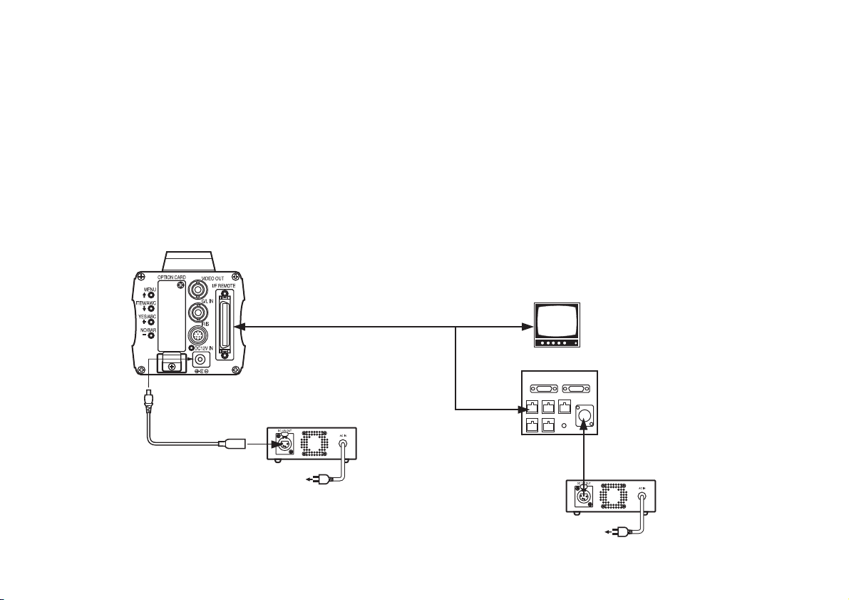
w CONNECTION OF A REMOTE OPERATION PANEL (ROP)
The ROP (AW-CB400) and the camera must be connected with the optional connecting cable AW-CA50T8.
1. Turn the OPERATE switch of ROP to OFF before connecting cables.
2. Connect the 50-pin connector of the connecting cable to I/F REMOTE connector of the camera.
The 10BASE-T cable must be connected to the ROP.
3. Turn the OPERATE switch of ROP to ON and the camera can be controlled remotely by the ROP.
MONITOR
Connecting cable AW-CA50T8 (10 m)
DC cable with ø6.5 plug
(supplied with AW-PS505A)
10BASE-T
cable
AC Adapter
AW-PS505A
- 29 (E) -
BNC
Remote Operation Panel AW-CB400
DC cable with 4-pin connector
(supplied with AW-PS505A)
AC Adapter
AW-PS505A
 Loading...