


Convertible Camera
AW-E750
AW-E655
AW-E650
AW-E350
Before attempting to connect, operate or adjust this product,
please read these instructions completely.
-2-
CAUTION
RISK OF ELECTRIC SHOCK
DO NOT OPEN
CAUTION: TO REDUCE THE RISK OF ELECTRIC SHOCK,
DO NOT REMOVE COVER (OR BACK).
NO USER SERVICEABLE PARTS INSIDE.
REFER TO SERVICING TO QUALIFIED SERVICE PERSONNEL.
The lightning flash with arrowhead symbol, within
an equilateral triangle, is intended to alert the
user to the presence of uninsulated “dangerous
voltage” within the product’s enclosure that may
be of sufficient magnitude to constitute a risk of
electric shock to persons.
The exclamation point within an equilateral
triangle is intended to alert the user to the
presence of important operating and
maintenance (service) instructions in the
literature accompanying the appliance.
WARNING:
TO REDUCE THE RISK OF FIRE OR SHOCK
HAZARD, DO NOT EXPOSE THIS EQUIPMENT
TO RAIN OR MOISTURE.
CAUTION:
TO REDUCE THE RISK OF FIRE OR SHOCK
HAZARD AND ANNOYING INTERFERENCE, USE
THE RECOMMENDED ACCESSORIES ONLY.
indicates safety information.
FCC Note:
This device complies with Part 15 of the FCC Rules. To
assure continued compliance follow the attached
installation instructions and do not make any
unauthorized modifications.
This equipment has been tested and found to comply with
the limits for a class A digital device, pursuant to Part 15
of the FCC Rules. These limits are designed to provide
reasonable protection against harmful interference when
the equipment is operated in a commercial environment.
This equipment generates, uses, and can radiate radio
frequency energy and, if not installed and used in
accordance with the instruction manual, may cause
harmful interference to radio communications. Operation
of this equipment in a residential area is likely to cause
harmful interference in which case the user will be
required to correct the interference at his own expense.
This Class A digital apparatus complies with Canadian
ICES-003.
Cet appareil numérique de la class A est conforme à la
norme NMB-003 du Canada.
For CANADA
The serial number of this product may be found on the
bottom of the unit.

-3-
CONTENTS
PREFACE ................................................................................................................................................................................ 4
FEATURES .............................................................................................................................................................................. 5
SPECIAL NOTES ON OPERATION ......................................................................................................................................... 6
PRECAUTIONS ....................................................................................................................................................................... 7
MAJOR OPERATING CONTROLS AND THEIR FUNCTIONS ................................................................................................. 9
MOUNTING ............................................................................................................................................................................ 13
FLANGE BACK ADJUSTMENT (FOR ZOOM LENS) ............................................................................................................... 15
IRIS GAIN CONTROL IN A LENS ........................................................................................................................................... 17
CONNECTIONS ...................................................................................................................................................................... 18
ADJUSTMENT ........................................................................................................................................................................ 23
USE MODE SETTING ............................................................................................................................................................. 29
MENU ITEM SETTING ............................................................................................................................................................ 31
SETTING AND CHANGING THE OPTIONAL CARDS ............................................................................................................. 54
SETTING TO INITIAL SET ....................................................................................................................................................... 56
APPEARANCE ........................................................................................................................................................................ 60
SPECIFICATIONS ................................................................................................................................................................... 64
STANDARD ACCESSORIES ................................................................................................................................................... 68

-4-
• The Panasonic AW-E750, AW-E655, AW-E650 and
AW-E350 are digital signal processing color video
cameras that incorporates three CCDs;
2/3" 3CCD (AW-E750)
1/2" 3CCD (AW-E655, AW-E650)
1/3" 3CCD (AW-E350)
A digital video signal processing system is packed in
a compact, lightweight body while assuring high
picture quality, high reliability and high performance.
• System setup and adjustments can be easily
performed by following the setup menu.
• Connection to peripheral devices, such as a RCU, a
RCB and a lens and the camera pan/tilt unit enables a
wide variation of system configurations.
PREFACE
• Option cards may also be installed.
❈ The following cards are not available for AW-E750,
AW-E655, AW-E650, AW-E350;
· AW-PB301 Component Studio Card
· AW-PB302 RGB Card: The camera unit
contains this function.
· AW-PB303 High-sensitivity Card:
The camera unit
contains this function.
· AW-PB304 SDI Card: Use AW-PB504.
· AW-PB306 Studio SDI Card: Use AW-PB506.
· AW-PB307 SVGA card
· AW-PB309 WEB card
· AW-PB310 IEEE 1394 Card

-5-
1. Digital video signal processing for high quality, high
reliability, high performance, lightweight and
compact size.
2. Resolution: 850 lines (HIGH BAND DTL: ON)
S/N ratio:
67dB (DNR ON) (AW-E750, AW-E655, AW-E650)
66dB (DNR ON) (AW-E350)
3. Minimum illumination:
0.00005 lx (AW-E750, AW-E655, AW-E650)
0.00015 lx (AW-E350)
4. The built-in CCD storage function and digital gain up
function provide an even higher degree of high
sensitivity.
5. RGB, Y/Pr/Pb and Y/C signal output circuits
provided.
6. Motorized filters containing IR through and ND
filters (1/16, 1/64) incorporated (model AW-E655
only).
7. Built-in automatic controls, including ATW, ELC, and
AGC.
FEATURES
8.CCD readout is switchable between field and frame
modes. Vertical resolution can be stepped up in
frame mode and it is effective for shooting still
objects.
9. The built-in synchronized scanning system reduces
noise in computer graphics.
10. Various correction circuits permit video reproduction
with high fidelity.
11. Chroma detail correction enables clear shots of dark
color objects.
12. A dark detail circuit provides natural edge
correction to any object in a dark scene.
13. A digital color matrix enables high fidelity color
images.
14. The 12-axis digital color matrix enables users’ to
create images of their choice.
15. Four use modes for each of your specific
applications can be selected.
16. SMPTE color bar is indicated on the monitor screen.
17. Remote control with a RCU, RCB or a Hybrid control
panel.

-6-
• Turn power off before connecting or disconnecting
cables.
• Connection or disconnection of any studio cable,
RCB cable or other cable to any unit of equipment
must be performed while power is off.
• While the camera is in automatic mode;
Shooting of bright objects in ELC operation mode
may result in a smeared picture unique to the CCD.
The ATW function under fluorescent illumination can
adversely change the white balance.
SPECIAL NOTES ON OPERATION
• There is a cooling fan inside.
Do not cover the port or otherwise block ventilation
during operation. Internal heat buildup can cause a
fire.
It is an expendable part, and must be replaced
about every 30 000 hours. (Whenever fan replacement is necessary, be sure to ask the store where
you purchased the set.) (AW-E750, AW-E655)

-7-
DON'TS
• Do not attempt to disassemble the camera, Remote
Control Unit (RCU) or other units. In order to prevent electric shock, do not remove screws or covers. There are no user-serviceable parts inside.
• Do not abuse the camera. Avoid striking, shaking,
etc. The camera contains sensitive components
which could be damaged by improper handling or
storage.
• Do not let the lens remain uncapped when the camera is not in use. If the lens is not installed, do not
leave the lens mount hole uncovered.
• Do not touch the surface of the lens or prism.
• Do not use strong of abrasive detergents when
cleaning the camera body.
• Do not aim the camera toward the sun, no matter
whether it is turned on or not.
• Do not expose the camera or Remote Control Unit
(RCU) to rain or moisture, and do not try to operate
the equipment in wet conditions. Do not operate the
camera or RCU if it becomes wet.
• Do not operate the camera or Remote Control Unit
(RCU) outdoors during a lightning storm.
• Do not use the camera in an extreme environment
where high temperatures or high humidity exist.
• Do not leave the camera and Remote Control Unit
(RCU) turned on when not in use. Do not unnecessarily turn the camera power on and offis 1o1o1oSy.
Do not block the ventilation slots.
• Do not cover the port otherwise block ventilation
during operation. Internal ho1o buildup can cause a
fire.
PRECAUTIONS

-8-
• Take immediate action if ever the camera or RCU
should become wet. Turn the power off and have
the unit checked by an authorized service facility.
• Follow normal safety precautions to avoid personal
injury.
• Use the camera in an environment where the temperature is within 14°F to 113°F (−10°C to +45°C),
and the relative humidity is within 30 % to 90 %.
• Always turn the power off when the camera is not
going to be used. Operate the camera and RCU
only when there is adequate ventilation.
DOS
• Refer any servicing to qualified service personnel.
• Handle the camera with care.
• Protect the precision made lens by placing the lens
cap over when the camera is not in use. If the lens
is not installed, protect the surface of the prism by
placing the body cap into the lens mount hole.
• Use a mild blower or lens cleaning tissue designed
for coated lenses, to clean the surface of the lens or
prism in the event that it should become dirty.
• Use a dry cloth to clean the camera if it is dirty. In
case the dirt is hard to remove, use mild detergent
and wipe gently.
• Use caution when operating the camera in the
vicinity of spot lights or bright lights, as well as light
reflecting objects and surfaces.
-9-
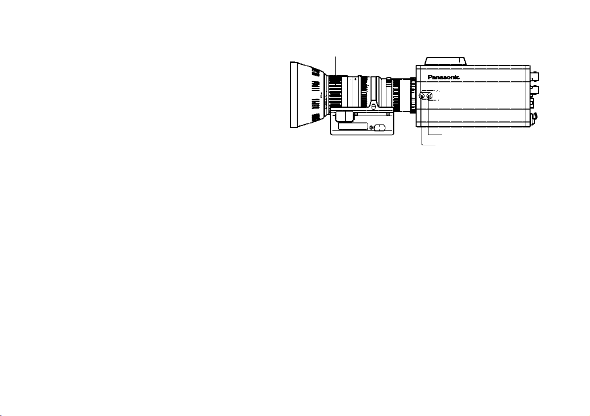
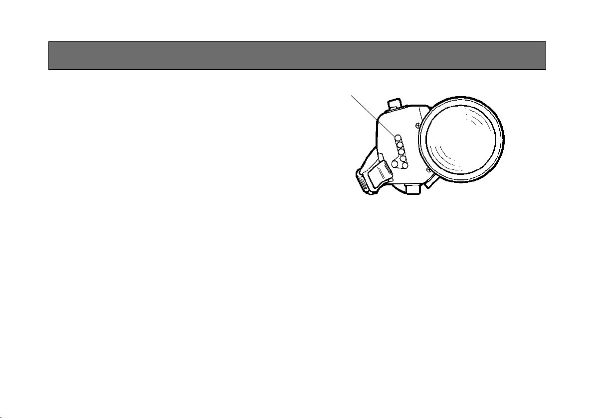
MAJOR OPERATING CONTROLS AND THEIR FUNCTIONS
r
t
-10-
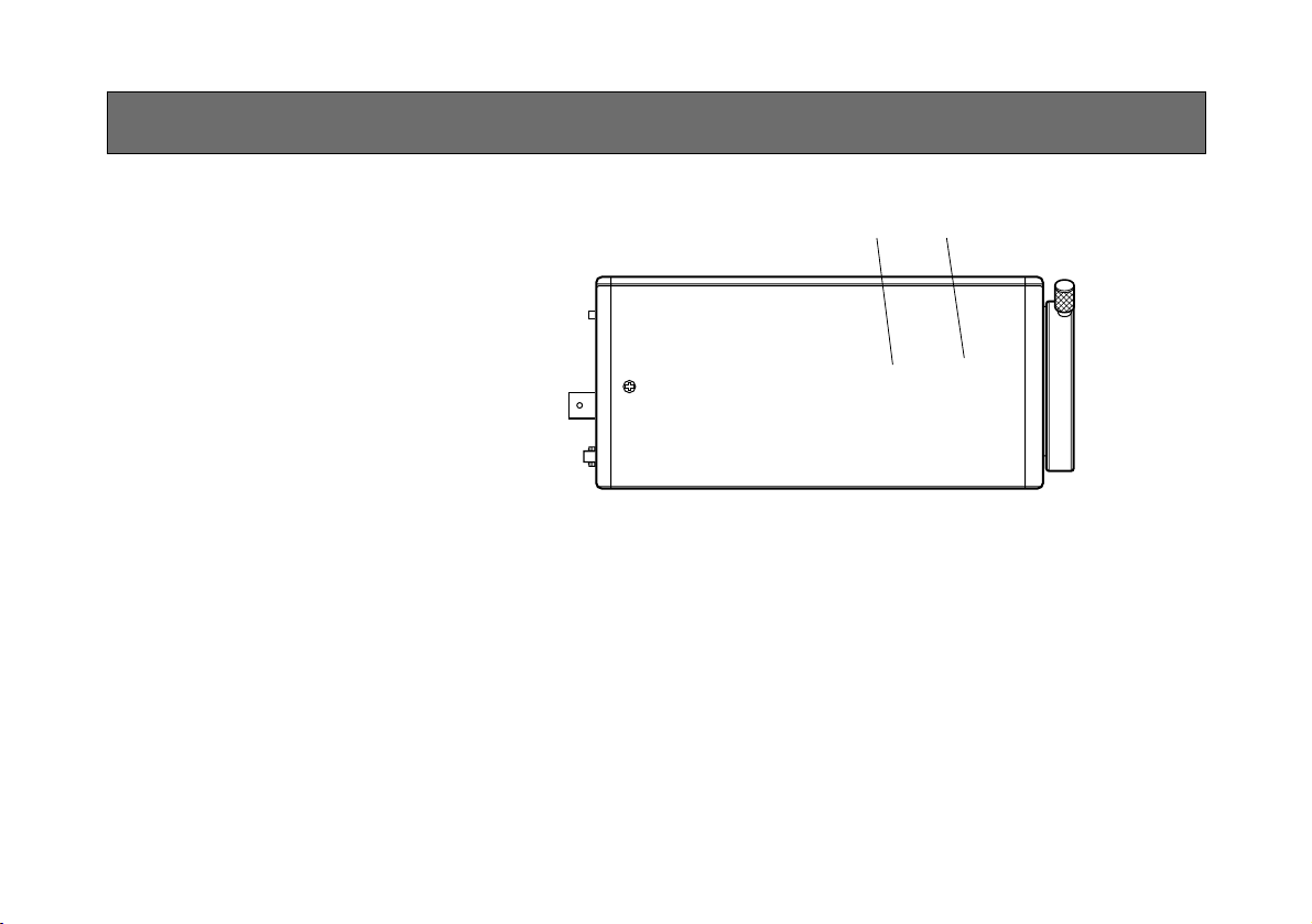
2. Lens fixing ring knob
Rotate the lens fixing ring knob counterclockwise
and remove the lens mount cap. Mount the lens on
the camera and rotate the lens fixing ring knob
clockwise in order to fix the lens securely.
3. Mic Jack (model AW-E655 only)
This is a ø3.5 mm mic jack which supports PLUG IN
POWER. Use the microphone which has more than
1kΩ of impedance, unbalanced.
4. Mounting hole
To install the camera on a wall or ceiling or to use a
pan/tilt head or tripod, secure the unit using this
screw hole (1/4"-20UNC) or using the accessory
mounting adaptor.
5. Cooling Fan (models AW-E750, AW-E655 only)
The cooling fan can be set to “Auto” or “OFF” on
the menu.
6. Expansion Slot
Remove the cover, and connect the expansion card
box.
<
>
?
@
;
=7
8
9
:
A
C
B
1. Lens Mount
2/3" Standard bayonet type (B4 mount) lens
(AW-E750)
1/2" Standard bayonet type (B4 mount) lens
(AW-E655, AW-E650)
1/3" C mount lens (AW-E350)
One of the lenses listed above or a microscope
adaptor is installed on this mount.
-11-
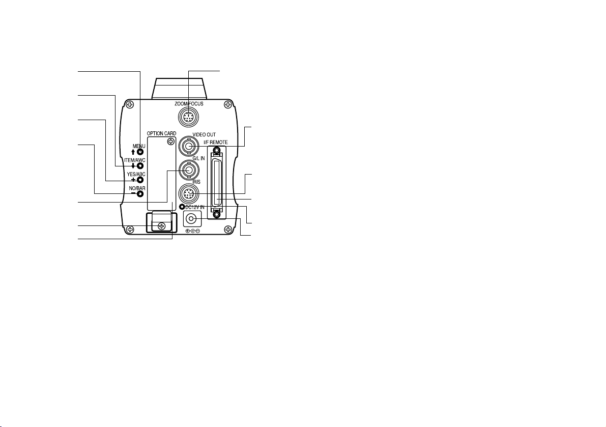
7. MENU Switch (MENU/A)
A menu will appear on the monitor screen when this
switch is pressed for about 5 seconds. This item
can be selected by pressing the switch while the
menu is on the screen.
8. ITEM/AWC Switch (ITEM/AWC/S)
The item just below can be selected by pressing
this switch while the menu is on the screen. When
the menu is not displayed or the camera is in shooting mode, the automatic white balance control can
be set with this switch.
9. YES/ABC Switch (YES/ABC/+)
The Sub Menu for each item of the Main Menu is
displayed when this switch is pressed while the
Main Menu is on the screen.
While the Sub Menu is displayed, any setting can
be brought up to a higher value with this switch.
When the menu is not displayed or the camera is in
shooting mode, the automatic black balance control
can be set with this switch.
10. NO/BAR Switch (NO/BAR/−)
The item just below can be selected by pressing
this switch while the Sub Menu is on the screen.
While the Sub Menu is displayed any setting can be
brought down to a lower value with this switch.
When the menu is not displayed or the camera is in
shooting mode, the color bar and the shooting
conditions are indicated by pressing the switch.
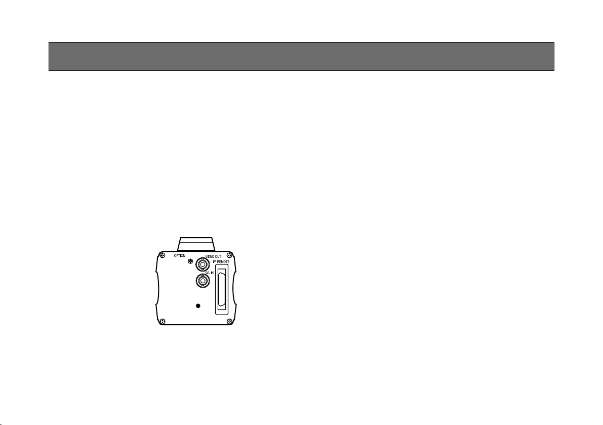
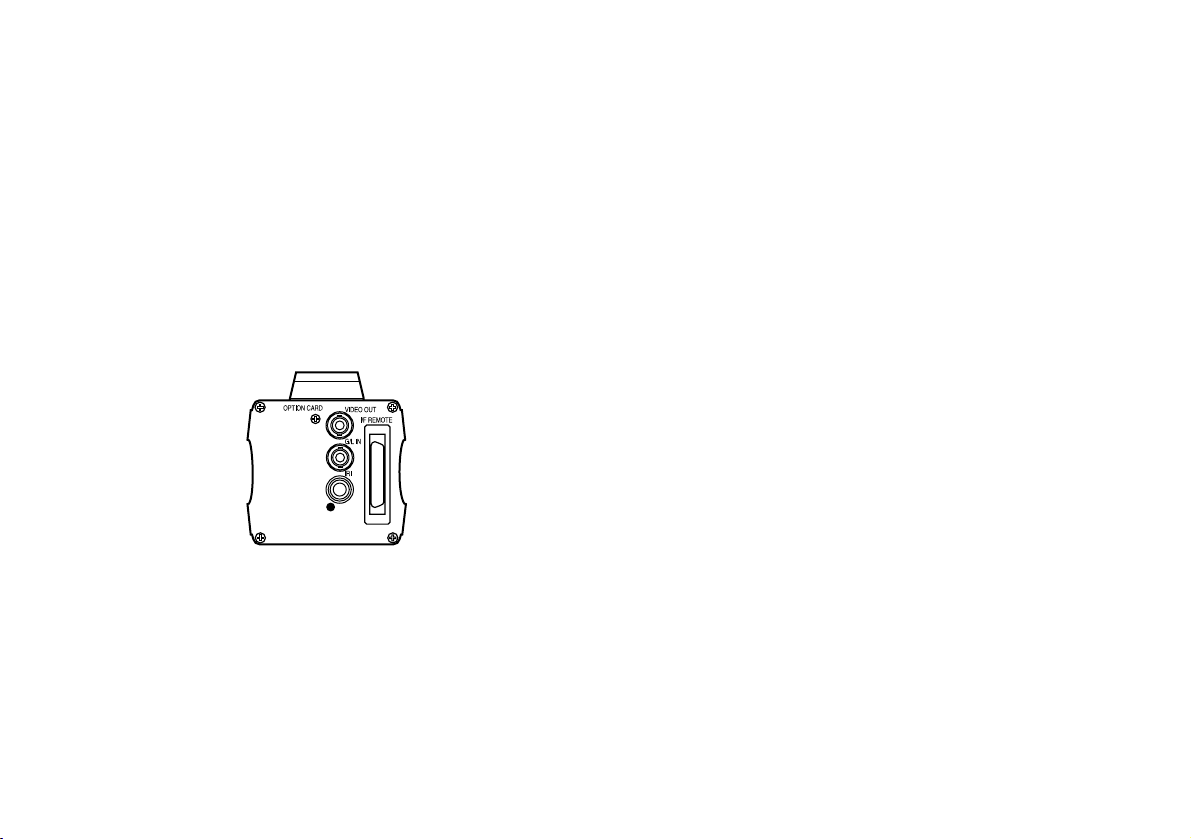
11. Video Output Connector (VIDEO OUT)
A composite video signal is provided at this connector.
12. Iris Connector (IRIS)
Input terminal for lens with an iris control function.
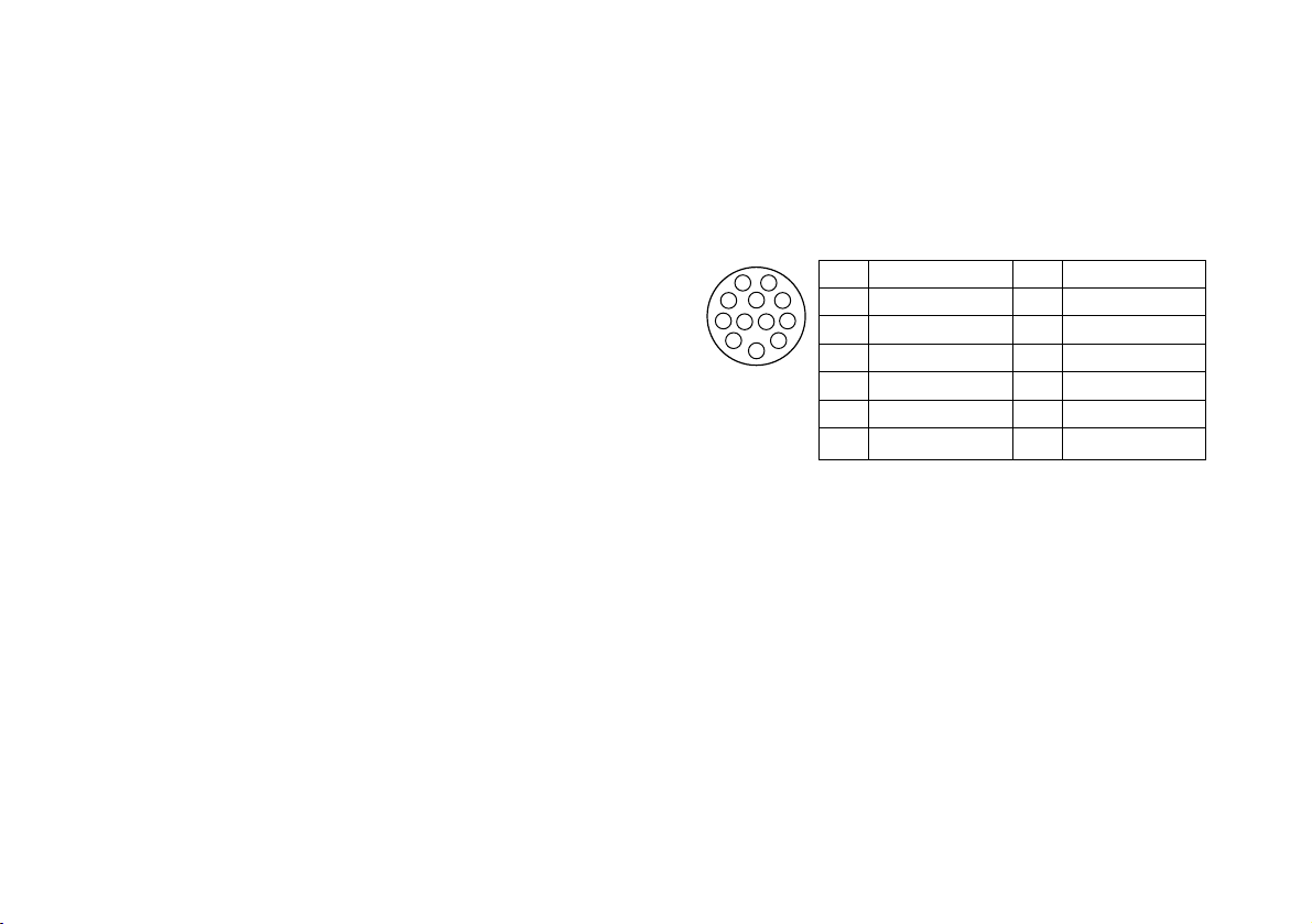
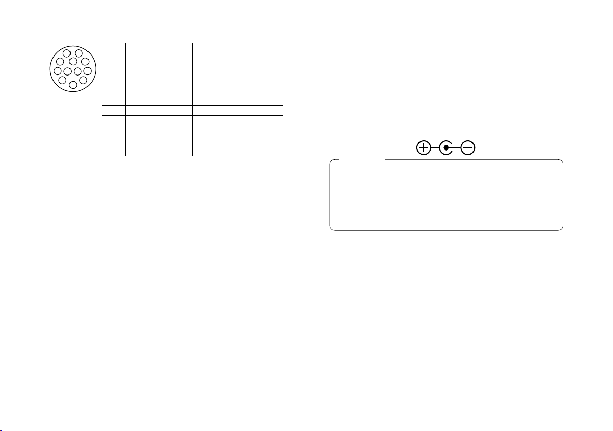
13. Zoom/Focus Connector (ZOOM/FOCUS)
(model AW-E655 only)
This connector is for the remote cable of the lens
and is a standard input connector for lenses with
remote functions for zooming and focusing.
When the camera is to be mounted on a Panasonic
pan/tilt head (such as the AW-PH300A), do not use
this connector — connect the remote cable of the
lens to the LENS I/F connector on the pan/tilt head
instead.
Pin No.
Signal
1 Return Control
2 Not Used
3 GND
4
Auto/Manual Control
5 Iris Control
6 Lens Power
Pin No.
Signal
7 Iris Follow
8
Auto/Remote Control
9 Not Used
10 Not Used
11 Not Used
12 Not Used
1
2
3
4
5
6
7
8
9
10
1112
-12-
14. I/F Remote Connector (I/F REMOTE)
Input terminal dedicated to control signals from the
optional Remote Control Box (RCB) (such as the
WV-CB700A) and the RCU (such as the
WV-RC700A, WV-RC550) and the camera pan/tilt
unit (such as the AW-PH300A).
• WV-CB700A is connected through the optional
RCB cable (AW-CA50T10/AW-CA50B10).
• WV-RC700A/WV-RC550 is connected through the
optional RCU cable (AW-CA50A26).
• AW-PH300A is connected through the optional
pan/ tilt unit cable (AW-CA50T15/AW-CA50A15).
• Use the camera/pan-tilt head connecting cable
(AW-CA50T29/AW-CA50C29) to connect the
AW-PH350 to the convertible camera.
17. G/L Input Connector (G/L IN)
Signals synchronized with the reference signal are
to be supplied to this connector when the camera is
to be synchronized with the reference signal BB.
18. Cable Clamp
Clamp the DC Power Supply Cable (AW-CA4T1)
connected to the DC 12 V Input Connector to prevent it from slipping out.
19. Optional Card Slot
Slot for inserting an optional card. For details, refer
to the manual for optional cards.
15. Power Indicator
Red LED lamp lights to indicate that the specified
DC power is supplied to the camera.
16. DC 12 V Input Connector (DC 12V IN)
12 V DC is supplied through the optional DC power
supply cable (AW-CA4T1).
(Recommended AC adaptor: AW-PS505)
1. Connect this to a DC 12 V class 2 power supply
only.
2. To prevent fire or shock, the UL listed wire
VW-1, style 1007 should be used as for the cable
for DC 12 V Input Connector.
Cautions
1
2
3
4
5
6
7
8
9
10
1112
Pin No.
Signal
Focus Mode
1 Position/Speed
/Auto Focus
2
Zoom Mode
Position/Speed
3 GND
4
Iris
Remote/Camera
5 Iris Control
6 Lens Power
Pin No.
Signal
Signal Control
7
(+5.0 V)
8 Focus Control
9 Zoom Control
10
Iris Mode
Position/Speed
11 +V (+7.5 V)
12 –V (+2.5 V)
-13-
MOUNTING
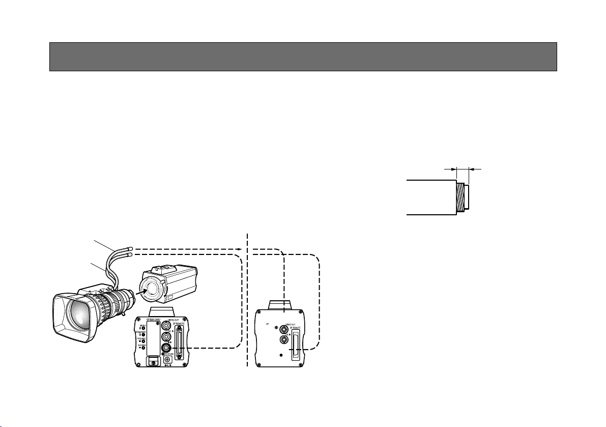
1. Lens Mounting
AW-E750, AW-E655, AW-E650
• Use the lens extension cable AW-CA12T12A
(6”/15 cm) if your lens cable is too short.
Rotate the lens fixing ring knob counterclockwise
and remove the lens mount cap. Mount the lens on
the camera and rotate the lens fixing ring knob
clockwise in order to fix the lens securely. Connect
the camera cable to the IRIS connector on the back
panel of the camera.
AW-E350
• A 1/3-inch C mount type of lens can be used.
Be absolutely sure that a lens whose mount
threads extend no more than 4.3 mm from the lens
mount surface is used. Use of any other kind of
lens may damage the camera unit.
• Some lenses need to be attached in a different
way. Therefore, reference should also be made to
the operating instructions that accompany the
lens.
Remove the lens mount cap, align the lens with the
thread ridges on the lens mount and screw it
securely into place.
Connect the lens cable to the IRIS connector.
Less than 4.3 mm
-14-
2. Fix the camera mounting base, pan/tilt unit, and tripod securely in the screw hole (1/4-20UNC) of the
camera or the mounting adaptor.
3. If the camera cannot be securely fixed, mount the
camera on a mounting bracket or the like with the
supplied rubber sheet between the camera and it.
4. To mount the camera on the pan/tilt head, use a
driver in order to fix it securely.
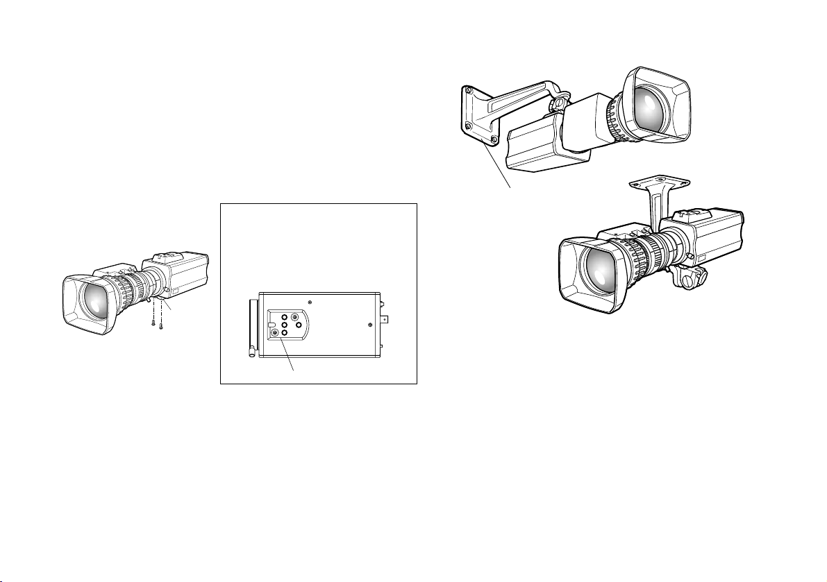
2. Camera Mounting
1. AW-E750 or AW-E655 models:
Use the screws provided to attach the accessory
mounting adaptor to the bottom panel of the
camera.
AW-E650 or AW-E350 models:
Use the screws provided to attach the accessory
mounting adaptor to the top or bottom panel of the
camera.
Use a screwdriver or similar to
tighten the screws to secure the
mounting adaptor.
Make sure that the mounting
adaptor is attached the right way
round.
$
Preventing the camera from falling or coming off
O
When attaching a camera to the pan/tilt head (AWPH300A, AW-PH350), follow the directions in the
Operating Instructions to fix the camera firmly in position.
In addition, link the camera to the pan/tilt head using the
safety chain and the mounting screws to help ensure the
camera does not fall.
O
When attaching the camera on any mounting or other
pan/tilt head, check that the mounting can safely bear the
total weight of the camera, lens, connection cables, etc., fix
the camera firmly in position using the prescribed tool, and
take appropriate measures to prevent the camera from
falling.
mounting adaptor
Mounting
adaptor
Camera Mounting Bracket (WV-831)
-15-
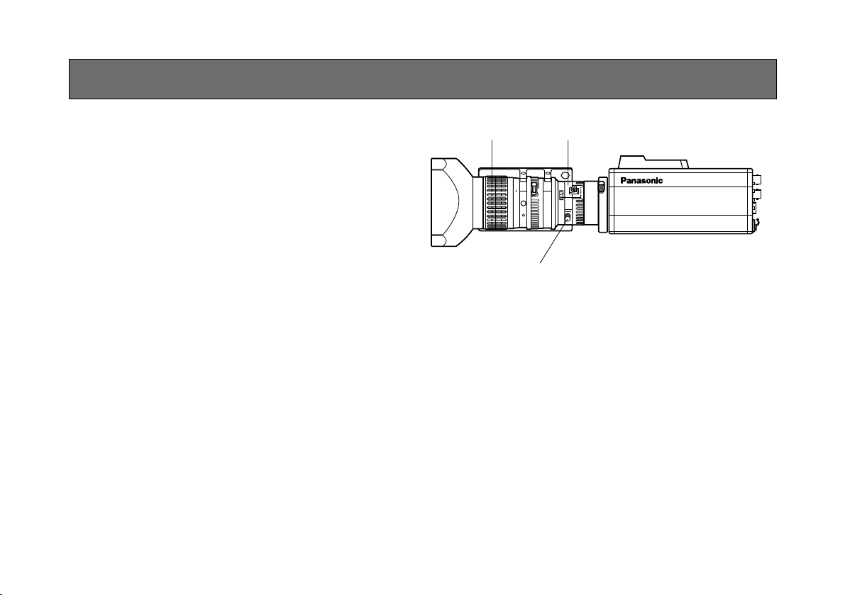
AW-E750, AW-E655, AW-E650
This adjustment will bring the subject into focus across
the whole range from the maximum telephoto position to
the widest angle position of the zoom lens.
1. Fully open the iris by shooting a dark object. (Iris
selection switch should be set to M.)
2. Loosen the flange back lock knob.
3. Aim the camera at any object over 2 meters away
from the camera.
4. Set the lens to its TELE end first and adjust its focus
with the focus ring.
5. Set the lens to its widest angle next and adjust its
focus with the flange back adjust ring.
6. Adjust the focus ring and the flange back adjust ring
alternately for the best focus within the zooming
range.
Tighten the flange back lock knob upon completion
of focusing.
7. Turn the iris selection switch to Position A.
30
10 m532
1.50
II1510751
5.5 10 20 40 77
FLANGE BACK ADJUSTMENT (FOR ZOOM LENS)
FOCUS Ring Flange back adjust ring
Flange back lock knob
AW-E750, AW-E655, AW-E650
-16-
AW-E350
This adjustment will bring the subject into focus across
the whole range from the maximum telephoto position to
the widest angle position of the zoom lens.
Perform this adjustment when back focusing is not
achieved with a fixed focus lens.
(Adjustment range: ±0.2 mm)
1. Fully open the iris by shooting a dark object.
2. Aim the camera at any object over 2 meters away
from the camera, remove the cap over the camera’s
flange back adjust screw, and loosen the LOCK
screw.
3. Set the lens to its TELE end first and adjust its focus
with the focus ring.
4. Set the lens to its widest angle next and turn the
FOCUS screw to adjust its focus.
5. Adjust the focus ring and FOCUS screw alternately
for the best focus within the the zooming range.
Tighten the LOCK screw upon completion of the
focusing.
FOCUS Ring
LOCK knob
FOCUS knob
AW-E350
-17-
IRIS GAIN CONTROL IN A LENS
An iris gain control hole is usually provided in the front
of the lens. Adjustment of the iris gain, with a screwdriver through the hole may be done as follows. (Shape
and location of the hole may vary depending on the
type of lens.)
1. Turn the iris selection switch to Position A (AUTO).
2. Rotate the iris gain control to the maximum gain,
but in a range where no hunting or oscillating of the
iris ring develops.
Iris gain control (G, S)
Automatic iris power zoom lens
-18-
Caution:
The connection and installation should be done by qualified service personnel or system installers.
Refer any servicing to qualified service personnel.
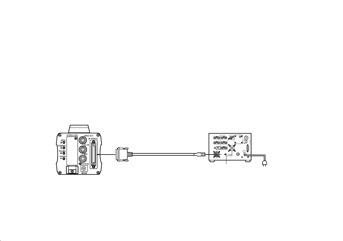
CONNECTIONS
■ CONNECTION OF DEVICE WITH A COMPOSITE INPUT CONNECTOR
• Connection to any device which has a composite input connector, such as a video monitor or a VTR, must be made
through the VIDEO OUT Connector.
• Power supply to the camera must be through the optional DC power supply Cable AW-CA4T1.
• For DC power supply, use the optional AC adaptor AW-PS505.
-19-
Connection to the RCU (WV-RC700A, WV-RC550) is
made through the optional RCU cable AW-CA50A26.
1. Turn RCU power off before connecting cables.
2. Set the cable selection switch of the RCU to MULTI
(in case of using the WV-RC700A)
3. Connect the 50-pin connector of the RCU cable to
the I/F REMOTE Connector of the camera.
4. Turn RCU power on and the power indicator lamp
will light. The camera can now be remote controlled
by the RCU.
Notes:
• The maximum extension distance between the
camera and WV-RC700A is 300 m. The maximum
extension distance between the camera and WVRC550 is 100 m.
• Use the following options for cable extension.
Studio Cable WV-CA26U15 (15 m/50 ft)
WV-CA26U30 (30 m/100 ft)
WV-CA26U100 (100 m/330 ft)
Cable Joint Adaptor
WV-CA26T26
■ CONNECTION OF A REMOTE CONTROL UNIT (RCU)
GEN-LOCKGEN-LOCKINAUXAUX
IN
AUTOAUTO
75Ω/Hi-Z/Hi-Z
AUTOAUTO
75 Ω/Hi-Z/Hi-Z
R/PR /CR/PR /C
OUTOUT OUTOUT
AUDIOAUDIO
SEE MANUALSEE MANUAL
VIDEO 1VIDEO 1
G/Y/YG/Y/Y VIDEO 2VIDEO 2
B/PB /BB/PB /B SYNCSYNC
S-VIDEOS-VIDEO
1 4
2 3
TALLYTALLY
CAMERA (MULTI)CAMERA (MULTI)
CABLE SELECTCABLE SELECT
FUSEFUSE
250V 1.25A250V 1.25A
TALKTALK
INCOMINCOM
RECEIVERECEIVE
CONTROLCONTROL
TALLY & INCOMTALLY & INCOM
MULTI OVPOVP
MPXMPX
MPXMPX
OUTPUTOUTPUT
Set to MULTI
WV-RC700A
RCU Cable
AW-CA50A26 (15 m)
-20-
■ CONNECTION OF A REMOTE CONTROL BOX (RCB)
The RCB (WV-CB700A) and the camera must be connected with the optional RCB cable AW-CA50T10.
1. Turn RCB power off before connecting cables.
2. Connect the 50-pin connector of the RCB cable to
I/F REMOTE connector of the camera. The 10-pin
connector must be connected to the RCB.
3. Turn RCB power on and the camera can be controlled remotely by the RCB.
Notes:
• The monitor output signals of the RCB attenuate
and deteriorate with cable length. It is recommended that the signals from the monitor output be used
for monitoring purposes only.
• No gen-lock signal is available from the RCB.
• If a longer distance (more than 3 m) is desired
between the camera and the RCB, use the following
optional cable.
AW-CA50B10 and WV-CA10B02 (2 m)
WV-CA10B25 (25 m)
WV-CA10B50 (50 m)
-21-
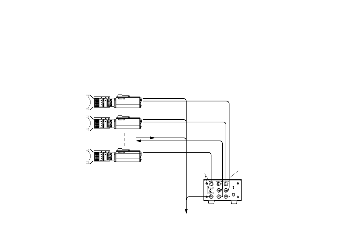
■ CONNECTION WITH MULTIPLE CAMERAS (COLOR LOCK MODE)
• An example of connection for VBS/BB input (Color lock
mode).
• One of the multiple cameras is used as the source of reference signals.
• Supply a synchronizing signal (BB) to the G/L Input
Connectors of each cameras.
• Do not switch off the camera used for supplying the
reference signals.
• Adjust the SC-phase and H-phase at the Video
Output Connector.
30
10 m532
1.50
II1510751
5.5 10 20 40 77
30
10 m532
1.50
II1510751
5.5 10 20 40 77
30
10 m532
1.50
II1510751
5.5 10 20 40 77
VIDEO OUT
CAMERA
Camera for External Sync
(or Special Effect Generator)
G/L IN
VIDEO OUT
OUTPUT
INPUT
Video Output
To Special Effect Generator or Monitoring System
Video
Distributor
WJ-300C
External Sync
Signal (BB)
-22-
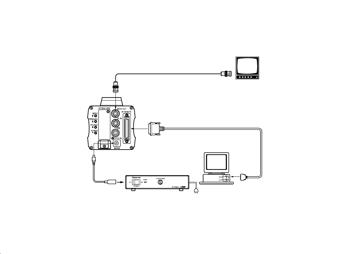
■ CONNECTION OF COMPUTER
The AW-CA50T9 PC control cable is required to control the camera using a computer. Consult your dealer for details.
The user is responsible for providing the software used to control the camera.
O I
FUSE
FUSE
DC Power Cable
AW-CA4T1
Computer
VIDEO OUT Connector
AC ADAPTOR AW-PS505
75 Ω Coaxial Cable
Composite Video
Input Connector
(VIDEO IN)
Video Monitor
RS-232C
PC Control Cable AW-CA50T9 (10m)
■ CONNECTION OF DEVICES WITH CAMERA PAN/TILT CONTROL SYSTEM
• Refer to the operating instructions of the pan/tilt head to connect camera to it.

-23-
■ AUTOMATIC WHITE BALANCE
CONTROL (AWC)
There are two white balance memories, “AWC A” or
“AWC B” for two different light sources color tempera-
tures, with the automatic white balance setting. Then,
when the two different light sources are encountered,
you may operate the camera properly by simply
change the white balance mode to either AWC A or
AWC B. There is no need to readjust the camera to the
ambient conditions.
* The preset conditions will be renewed whenever
you input new conditions.
1. Turn the white balance selection switch to either
“AWC A” or “AWC B” of RCU or select the white
balance mode either AWC A or AWC B by menu.
2. Aim the camera at a white object (a white wall or a
white handkerchief) and zoom in to enlarge the
image as much as possible.
[ADJUSTMENT by CAMERA]
3. In normal shooting mode:
Press the ITEM/AWC switch for over 2 second.
[ADJUSTMENT with the RCU (RCB, Hybrid control
panel)]
4. When the AUTO set switch is turned to AWC, the
white balance will be automatically set. While the
system is being set, auto warning indicator (LED)
blinks and it goes out when the white balance setting is completed. If the lamp remains lit, the setting
must be tried again.
RCU (RCB)
CAMERA
ADJUSTMENT
ITEM/AWC
Switch
AUTO LED
AUTO set Switch

-24-
Notes:
• For white balance setting aim the camera at a
white object and try to position it in the center of
the monitor screen. The object must appear in
over 10 % of the total monitor screen area. Try
to avoid overly bright objects in the scene.
• White balance may not be correctly set if the
lighting of the object is too weak.
• Since the camera has a built-in memory, the set
white balance will remain in the memory even if
power is turned off. Therefore, it is not necessary to reset the white balance if the color temperature of those objects remains unchanged.
However, it must be reset if the color temperature changes, such as when you move from
indoors to outside, or vice versa.
• When the camera is used without a RCU or
RCB red/blue gain adjustment of painting setting will be automatically reset to ±0 after setting the white balance. (painting setting in only
USER MODE.)
The white object must occupy over
10 % of the monitor screen area.
■ AUTOMATIC TRACKING WHITE
BALANCE SETTING (ATW)
White balance will be automatically set to continuously
match changes of light source and color temperature
while the white balance setting is set to ATW.
Notes: • ATW might not function properly when high bright-
ness light (ex. fluorescent lamp) beams into a
screen.
• White balance may not be accurately set if there
is no white object in the scene being shot
.
■ MANUAL WHITE BALANCE SETTING
[ADJUSTMENT by CAMERA]
Manual setting is possible in USER MODE only.
1. Select the white balance mode either AWC A or
AWC B by menu.
2. Aim the camera at a large white object. Press the
ITEM/AWC switch for over 2 second.
3. Adjust the red gain/blue gain control in the PAINTING item of Color Set sub menu of USER MODE
until the carrier wave of the white portion of the
video signal is at the minimum width or the white
object in the monitor screen appears pure white.
(Use an oscilloscope or a waveform monitor for precise adjustment.)
[ADJUSTMENT with the RCU (RCB)]
After AWC setting, adjust the R/B GAIN controller in the
same way as described in Step 3 above.

-25-
■ RESET TO 3 200K OR 5 600K WHITE
BALANCE
When the white balance setting is set to either “P SET
3 200K” or “P SET 5 600K” the white balance will be
automatically set to the color temperature 3 200K or
5 600K, respectively.
■ BLACK BALANCE ADJUSTMENT
• Close the lens.
If the motor drive lens is controlled from the camera, the lens is automatically closed when the black
balance is adjusted.
• When the camera is used without a RCU or RCB,
R/B pedestal adjustment of painting setting will be
automatically reset to ±0 after setting the black balance. (painting setting in only USER MODE.)
[ADJUSTMENT by CAMERA]
Press the YES/ABC switch for over 2 seconds and the
black balance will be set automatically in 10 seconds.
Minimize the carrier wave using
the red & blue gain controls
Waveform for white
balance set chart

-26-
■ TOTAL PEDESTAL LEVEL ADJUSTMENT
(Use an oscilloscope or a waveform monitor for this
adjustment.)
This step is to adjust the black levels (pedestal levels)
of two or more cameras to be the same.
[ADJUSTMENT by CAMERA]
1. Close the lens.
2. Select Pedestal item in the brightness setting Sub
Menu (Select [Pedestal] in the [Iris, Shutter, Gain
Set] sub menu in USER MODE.)
3. Set the pedestal level to 5 IRE (0.035 V) with the
YES/ABC switch or the NO/BAR switch.
[ADJUSTMENT with RCU (RCB, Hybrid control panel)]
Adjust the pedestal level to 5 IRE with the total
pedestal adjustment.
NO/BAR Switch
YES/ABC Switch
5 IRE
(0.035 V)
TOTAL PEDESTAL
**Brightness Set**
Picture Level ±0
Light PEAK/AVG 0
Light Area Top Cut
Auto ND(ELC) (OFF)
Auto Gain Up (OFF)
AGC Max Gain (---)
Manual Gain Up (0dB)
Digital Gain Up 0dB
Charge Time OFF
Pedestal (±0)
Return

-27-
[ADJUSTMENT by CAMERA]
1. Press the NO/BAR switch for over 5 seconds to display the color bar.
2. Select [G/L Adjustment] on the main menu, then
select [H PHASE] on the submenu.
3. Adjust the horizontal phase with the YES/ABC and
NO/BAR switch.
External gen-lock input signal
(black burst output of special
effect generator)
Video signal
[ADJUSTMENT with RCU (RCB, Hybrid control panel)]
Use the horizontal phase control.
■ GEN-LOCK ADJUSTMENT
Phase adjustments must be performed with the camera
or the RCU (RCB) when external synchronizing signals
are supplied to the system in cases where multiple
cameras are used or peripheral devices are connected.
● HORIZONTAL PHASE CONTROL
Observe the waveform of the external synchronizing
input signal (black burst signal) and video output signal
on a two-channel oscilloscope. Then match the horizontal phase of both signals by adjusting them with the
cameras or RCU's horizontal phase control.
Adjust the horizontal phase
NO/BAR Switch
YES/ABC Switch
**G/L Adjustment Set**
H Phase (±0)
SC Coarse ( 1)
SC Fine (±0)
Color Bar Set 7.5IRE
Return

-28-
● COLOR PHASE ADJUSTMENT
Supply the output signal (split color bar) from the color
special effect generator to a color monitor or vectorscope. Adjust the color phase of the camera.
[ADJUSTMENT with RCU (RCB, Hybrid control panel)]
Use the subcarrier phase coarse adjustment control
and subcarrier phase fine control.
* It is recommended that a vectorscope be used for
maximum accuracy in color phase adjustment.
[ADJUSTMENT by CAMERA]
1. Press the NO/BAR switch for over 5 seconds for the
color bar mode.
2. Select [G/L Adjustment] on the main menu, then
select [SC Coarse] on the sub menu.
3. Make coarse adjustment with the YES/ABC switch
and the NO/BAR switch.
CAUTION:
When horizontal phase adjustment is required using
RCU (RCB) or Hybrid Control Panel, BAR/CAM switch
should be set to BAR. Horizontal phase cannot be
adjusted if the switch is in the CAM position. After
adjustment set BAR/CAM switch back to CAM.
CAUTION:
When color phase adjustment is required using RCU
(RCB) or Hybrid Control Panel, BAR/CAM switch should
be set to BAR. Color phase cannot be adjusted if the
switch is in the CAM position. After adjustment set
BAR/CAM switch back to CAM.
4. Select [SC Fine] on the sub menu. Perform fine
adjustment with the YES/ABC switch and the
NO/BAR switch.
**G/L Adjustment Set**
H Phase (±0)
SC Coarse ( 1)
SC Fine (±0)
Color Bar Set 7.5IRE
Return
Color bar of
camera
Color bar of special
effects generator
Sprit line

-29-
■ Use Mode Setting
The camera has four use modes, and various functions
for four use modes have been preset.
Functions can be set as best suited to each use mode.
• Halogen mode
Suited to indoor shooting, such as at weddings,
parties, lecture meetings, events, etc.
Settings can be changed using a simple menu.
• Fluorescent mode
Suited to indoor shooting under fluorescent lighting.
Settings can be changed using a simple menu.
• Outdoor mode
Suited to outdoor shooting.
Settings can be changed using a simple menu.
• User mode
Settings can be changed using a detail menu.
■ SETTING BY CAMERA
1. Turn the camera on while keeping the MENU switch
depressed.
The use mode setting menu shown at right appears
on the monitor screen and one of the use mode
blinks.
2. Press the MENU switch, ITEM/AWC switch, or
NO/BAR switch to let the desired use mode blink.
MENU switch (A): The blinking item moves up by
one.
ITEM/AWC switch (S), NO/BAR switch (–): The
blinking item moves down by one.
3. Press the YES/ABC Switch.
The blinking use mode comes into effect. After the
use mode setting menu is shown for about 5 seconds, the camera returns to be ready for operation.
Then, the camera operates in the selected use
mode.
USE MODE SETTING
**Use Mode Set**
Halogen
Fluorescent
Outdoor
User

Operation mode
-30-
■ SETTING BY RCU (RCB) OR HYBRID
CONTROL PANEL
An operation mode is selected depending on the position of the scene file switch.
Halogen Mode
Fluorescent Mode
Outdoor Mode
User's Mode
Scene File
Switch
Position of
RCU (RCB)
1
2
3
USER SET
Scene File
Switch
Position of
Hybrid control
panel
1
2
3
4
CAMERA RCU (RCB) Hybrid Control Panel
ITEM/AWC
YES/ABC
NO/BAR
MENU
SCENE
FILE
Switch

-31-
MENU ITEM SETTING
■ MENU ITEM SETTING
• Each of the four use modes of the camera has a
main menu. (Shown at right)
• Each item of the main menu has a submenu, which
consists of several settings.
• These settings have been preset to the optimum
values to suit each use mode, and can be changed
to suit actual shooting conditions.
• They can be set from the camera and RCU (RCB).
They can also be set from the hybrid control panel
using the switches, but the setting items are limited
because the menu is not shown.
● MAIN MENU SCREEN
**Halogen Mode Set**
Brightness Set
Color Set
G/L, Color Bar Set
Sharpness(DTL) Set
Other Set
(Option Card Set)
Initialize Data
(End)
**User Mode Set**
Iris, Shutter, Gain Set
Color Set
G/L, Color Bar Set
Detail Set1 Detail Set2
Color Matrix Set
Other Set1 Other Set2
(Option Card Set)
Initialize Data
(End)
Main Menu of Halogen,
Fluorescent, Outdoor Mode
Main Menu of User Mode
Use Mode
Blinking
Notes:
• Composite signals are output from the video
output regardless of the position ENC/VF of the
RCU (RCB) user set switch.
• [End] is displayed only in setting from the camera alone.
• [Option Card Set] is shown only when an
optional card is inserted.
**G/L Adjustment Set**
H Phase (±0)
SC Coarse ( 1)
SC Fine (±0)
Color Bar Set 7.5IRE
Return
❈ When the color bar signal is output from camera,
“G/L, Color Bar Set” is displayed.

-32-
■ SETTING
1. From the camera alone:
Keep the MENU switch depressed for 5 seconds or more.
From RCU (RCB):
Set the user set switch in the pocket to the ON
position.
The main menu appears on the monitor screen.
2. Each time the MENU switch (A), ITEM/AWC switch
(S), or NO/BAR switch (−) is pressed, the blinking
item moves up or down.
3. When the YES/ABC switch is pressed after selecting the desired item to blink, the submenu for the
selected item appears on the screen.
4. Select the desired item to be changed in its settings
using the the MENU switch (A) and ITEM/AWC
switch (S).
5. Press the YES/ABC switch (+) or NO/BAR switch (–)
to change the settings.
6. Select [Return] using the MENU switch and ITEM/
AWC switch, then press the YES/ABC switch to
return to the main menu.
7. After changing the settings, take the following
steps.
Camera alone: Select [End] using the MENU
switch and ITEM/AWC switch and press the
YES/ABC switch.
RCU (RCB): Set the user set switch in the pocket to
the OFF position.
The camera will now operate according to the new
settings.
CAMERA
RCU (RCB)
ITEM/AWC
YES/ABC
NO/BAR
MENU
USER SET SWITCH

-33-
• Settings enclosed in parentheses can be set with the RCU (RCB) switch or VR in RCU (RCB) mode.
• To return to the initial settings, refer to page 56.
■ SUB MENU (Halogen Mode, Fluorescent Mode, Outdoor Mode)
**Brightness Set**
Picture Level ±0
Light PEAK/AVG 0
Light Area Top Cut
Auto ND(ELC) (OFF)
Auto Gain Up (OFF)
AGC Max Gain (---)
Manual Gain Up (0dB)
Digital Gain Up 0dB
Charge Time OFF
Pedestal (±0)
Return
**Color Set**
Chroma Level ±0
Flesh Tone ±0
White Bal (AWC A)
ATW Speed -- Nega/Posi Posi
Return
**G/L Adjustment Set**
H Phase (±0)
SC Coarse ( 1)
SC Fine (±0)
Color Bar Set 7.5IRE
Return
**Sharpness(DTL) Set**
DTL Select Sharpness
Level (High)
Noise Suppress OFF
Clean DNR OFF
3D-DNR OFF
DTL Flesh Tone Mid
Return
**Other Set**
Contrast(Gamma) Mid
Shutter Speed (OFF)
Synchro Scan -- V Resolution Normal
Baud Rate 9600bps
Component Y/Pr/Pb
Digital Extender OFF
Fan Auto
Auto Focus OFF
Filter Normal
Return
2
Color Set Display
4
Sharpness (DTL) Set Display
5
Other Set Display
3
G/L Adjustment Set Display
1
Brightness Set Display
1 ------2 ------3 ------4 ------5 ------6 ---------7 ------8 ------9 -------
10 -------
1 ------2 ------3 ------4 ---------5 -------
1 ------2 ------3 ------4 -------
1 ------2 --------3 ------4 ------5 ------6 -------
1 ------2 ------3 --------4 ------5 ------6 ------7 ------8 ------9 -------
10 -------

• ON is automatically selected when the electronic
shutter (5-2) on the submenu [Other Set] is set to
[Auto ND]. OFF is selected when other than [Auto
ND] is selected.
• ON is selected when the SHUTTER switch is set
to [ELC] in RCU (RCB) mode, and OFF is selected when it is set to other than [ELC].
-34-
■ Setting and Changing of the
Setting (Halogen Mode,
Fluorescent Mode, Outdoor Mode)
1
Brightness Set Display
1. Video Level Adjustment [Picture Level: –50 to +50]
Convergence level of AUTO IRIS/AUTO GAIN UP/
AUTO ND (ELC) can be adjusted.
2. Detecting Ratio Adjustment
[Light PEAK/AVG: P50 to A50]
The ratio of AUTO IRIS/AUTO GAIN UP/AUTO ND
(ELC) detected peak to average can be adjusted
within a predetermined range.
3. Photometric Measurement Method Setting
[Light Area: All, Center, Top cut, BTM cut, R/L cut]
A photometric measurement method can be selected
for AUTO IRIS/AUTO GAIN UP/AUTO ND (ELC).
All: All the screen area is measured.
Center: The screen is measured mainly in the center
area, about one-third of both the top and bottom
and one-third of both the right and left portions of
the screen are excluded from measurement.
Top cut: About one-third of the top part of the screen
is excluded from measurement.
BTM cut: About one-third of the bottom portion of the
screen is excluded from measurement.
4. Auto ND (ELC) Setting [Auto ND (ELC): ON, OFF]
This cannot be set unless either “OFF” or “Auto” has
been set for the CCD storage time setting (1-9).
ON: The electronic shutter is controlled to automati-
cally adjust the luminance.
OFF: Luminance is not automatically adjusted by the
electronic shutter.
R/L cut: About one-third of both the right and left
portions of the screen are excluded from measurement.
Notes
SHUTTER Switch
RCU (RCB)

-35-
5. Auto Gain Up Control Setting
[Auto Gain Up: OFF, ON]
This cannot be set when “Auto” has been set for the
CCD storage time setting (1-9).
OFF: The light quantity is not adjusted
automatically.
ON: The light quantity is adjusted automatically.
The maximum to which the gain can be
increased using the auto gain up function is
selected by the AGC maximum gain setting (1-6).
6. AGC Maximum Gain
[AGC Max Gain: 6dB, 12dB, 18dB, 24dB, N/Eye L,
N/Eye H] (AW-E750, AW-E655, AW-E650)
[AGC Max Gain: 6dB, 12dB, 18dB, 24dB, N/Eye]
(AW-E350)
This is used to set the maximum amount to which the
gain can be increased when “ON” has been selected
as the auto gain up setting (1-5).
7. Manual Gain Up Control Setting
[Manual Gain Up: 0 dB to 30 dB, N/Eye L, N/Eye H]
(AW-E750, AW-E655, AW-E650)
[Manual Gain Up: 0 dB to 30 dB, N/Eye] (AW-E350)
Manual setting is possible only when the Auto Gain
Up control (1-5) is in the OFF position.
0 dB: 0 dB should be selected in normal cases.
1 dB to 30 dB: Use this range if sufficient video out-
put cannot be obtained even when the lens iris is
opened in shooting dark scenes.
AW-E750, AW-E655, AW-E650
Night Eye L: Use this setting if it is not possible to
achieve a satisfactory video output even at 30 dB.
Night Eye H: Use this setting if it is not possible to
achieve a satisfactory video output even at the
Night Eye L setting.
AW-E350
Night Eye: Use this setting if it is not possible to
achieve a satisfactory video output even at 30 dB.
• In case of settings on the camera alone or when
the iris switch on the RCU (RCB) is at [AUTO], the
Auto Gain Up control may not operate if the lens
iris switch is in the manual position.
• When the AGC switch on the hybrid control panel
is set to AGC, the Auto Gain Up control operates
in the HIGH position.
Notes
Hybrid Control Panel
AGC Switch

9. CCD Storage Time Setting
[Charge Time: Auto, OFF, 1/30s, 1/15s, 1/8s, 1/4s,
1/2s, 1s, 2s]
This is used to set the CCD storage time.
Auto: ALC is performed followed by AGC and then
by the data storage, and the camera automatically adjusts the light quantity.
If “ON” is selected as the auto ND (ELC) setting
(1-4), ELC is performed followed by ALC, AGC
and then by the data storage in this order, and
the light quantity is automatically adjusted.
The electronic shutter setting (5-2) cannot be
changed.
OFF: Under normal circumstances, this setting is
used.
1/30s to 2s: Use this setting if it is not possible to
achieve a satisfactory video output even when
the gain up setting is used.
The auto ND (ELC) setting (1-4) and electronic
shutter setting (5-2) go “OFF” and cannot be
changed.
❈ If the images (CCD read out (mode) setting
(5-4)) have been set to “Fine”, 1/15s to 2s is
selected as the storage time setting, and the
sensitivity is set to about one-half of that
obtained with when they have been set to
“Normal”.
-36-
• Only 0 dB, 9 dB, or 18 dB can be selected in
case of using the RCU (RCB).
• 0 dB when the manual GAIN switch on the hybrid
costti panely is t LOWB, 9 dB when it is t MIDB, o

-37-
2
Color Set Display
1. Chroma Level Adjustment
[Chroma Level: –3 to +3]
Chroma Level can be decreased or increased to
any of three levels each.
2. Skin Color Adjustment [Flesh Tone: –3 to +3]
Skin color can be decreased or increased to any of
three levels each.
3. White Balance Setting
[White Bal: ATW, AWC A, AWC B, P SET 3 200K,
P SET 5 600K]
ATW: The white balance is automatically adjusted to
be always right.
AWC A, AWC B: Once the white balance is adjusted
with the ITEM/AWC switch on the back of the
camera, it is no longer necessary to set the white
balance again if you simply select AWC A or
AWC B, provided that the camera is used under
the same conditions.
Fine color adjustment can be made after setting
AWC by red/blue gain adjustment in user mode
or from the RCU (RCB).
P SET 3 200K: The white balance is adjusted to
3 200K illumination.
10. Black Level Setting [Pedestal: –150 to +150]
The black level (pedestal) of the luminance (Y) signal
can be set. Used in adjusting the black levels of two
or more cameras.

-38-
3
G/L Adjustment Set Display
1. Horizontal Phase Adjustment
[H Phase: –206 to +49]
Horizontal phase can be adjusted when a genlock
signal is supplied.
2. Sub Carrier Phase Coarse Adjustment
[SC Coarse: 1, 2, 3, 4]
Coarse adjustment of subcarrier phase can be made
when a genlock signal is supplied.
3. Subcarrier Phase Fine Adjustment
[SC Fine: –511 to +511]
Fine adjustment of subcarrier phase can be made
when a genlock signal is supplied.
4. Color Bar Setup Setting
[Color Bar Set: 0.0 IRE, 7.5 IRE]
The setup level of color bar can be adjusted.
4. ATW Speed Setting
[ATW Speed: SLOW 2, SLOW 1, MID, FAST 1, FAST 2]
ATW Speed can be set.
5. Negative/Positive Selection
[Nega/Posi: Posi, Nega]
Posi: Normal image
Nega: Image is shown reversed in darkness and
color.
Neither P SET 3 200K nor P SET 5 600K can be
set from the RCU (RCB) or the hybrid control
panel.
Note
P SET 5 600K: The white balance is adjusted to
5 600K illumination.

-39-
3. Noise Suppress Level Setting
[Noise Suppress: OFF, LOW, HIGH]
Screen noise can be reduced when Detail Level setting (4-2) is at HIGH or LOW.
4. Clean DNR Setting [Clean DNR: HIGH, LOW, OFF]
This enables the clean DNR effect to be selected.
5. 3D-DNR Setting [3D-DNR: OFF, Low, Mid, High]
This enables the 3D-DNR effect to be selected.
❈ When “Mid” or “High” is selected, the noise is
reduced but lag increases.
6. DTL Flesh Tone Setting
[DTL Flesh Tone: LOW, MID, HIGH]
LOW: The roughness of the flesh tones is minimized.
MID: This is the standard setting.
HIGH: The outline compensation for the flesh tones is
accentuated.
2. Detail Level Setting [Level: OFF, LOW, HIGH]
Detail level can be adjusted when Detail Select setting is at Normal. Super DTL level can be adjusted
when it is at Super DTL.
In case of using the RCU (RCB), the above can be
adjusted with the contour correction switch (DTL).
4
Sharpness (DTL) Set Display
1. Detail Select Setting
[DTL Select: Sharpness, Super DTL]
If contour correction is not sufficient at the
Sharpness position when Detail Level setting is set
to LOW or HIGH, select the Super DTL position.
Neither Sharpness nor Super DTL is valid for
contour correction if Detail Level setting is in the
OFF position.
Note
RCU (RCB)
DTL Switch

-40-
Shutter Speed
OFF
1/100
1/250
1/500
1/1 000
1/2 000
1/4 000
1/10 000
Required luminance ratio
1
2
4
8
16
32
64
160
Synchro-scan
-
100.3 Hz
250.0 Hz
492.2 Hz
984.4 Hz
1.969 kHz
3.938 kHz
7.875 kHz
4. CCD Read Out Mode Setting
[V Resolution: Normal, Fine]
Normal: Normal image. (CCD storage will be by field
storage.)
Fine: Vertical resolution increases. (Vertical resolution
is raised without increasing residual images by
frame storage and Electronic shutter.)
Normal is recommended for general use because sensitivity will decrease at the Fine setting.
3. Electronic Shutter Synchro Scan Setting
[Synchro Scan: 60.34Hz to 15.75kHz]
This setting is possible only when Electronic Shutter
setting (5-2) is at S/Scan.
Horizontal bar noise can be reduced by synchroscan adjustment in shooting workstation scenes, for
example.
❈ For luminance settings at each shutter speed and
synchro-scan shutter speed, refer to the table
below.
• In case of using the RCU (RCB), none of the
shutter speeds − 1/250, 1/2 000, 1/4 000, and
1/10 000 can be selected.
• In case of using the hybrid control panel, only
OFF, 1/100, or Auto ND (ELC) can be selected.
• If the lens iris switch is at M (Manual) when operating the camera alone or when the iris switch on
the RCU (RCB) is at AUTO, Auto ND may not
function. Set the lens iris switch to A (Auto).
• Flickering may increase at Auto ND under fluorescent lights.
• Auto ND is automatically selected if Auto ND
(ELC) setting is set to ON.
Notes
5
Other Set Display
1. Contrast Adjustment
[Contrast (Gamma): LOW, MID, HIGH]
The contrast can be adjusted to any of three levels.
2. Electronic Shutter Setting
[Shutter Speed: OFF, 1/100 to 1/10 000, S/Scan, Auto ND]
OFF: Electronic shutter is turned off.
1/100, 1/250, 1/500, 1/1 000, 1/2 000, 1/4 000, 1/10 000:
Electronic shutter operates at one of these
speeds as selected.
S/Scan (Synchro Scan): Electronic shutter operates
at the speed set with the electronic shutter synchro-scan setting (5-1).
Auto ND: Electronic shutter is controlled to automati-
cally adjust the luminance. (ELC)

-41-
5. PC Control Access Speed Setting
[Baud Rate: 1 200bps, 2 400bps, 4 800bps, 9 600bps]
Select a communication speed in controlling the
camera from the computer.
6.
Component Output Setting
[Component: RGB, Y/Pr/Pb, Y/C]
This enables RGB, Y/Pr/Pb or Y/C to be selected as
the component signals which are to be output from
the I/F REMOTE connector.
7. Digital Extender Setting
[Digital Extender: OFF, ON]
OFF: Under normal circumstances, this setting is
used.
ON: An extender effect which is approximately 1.5
times greater is achieved.
However, the resolution drops when the digital
extender is set to “ON”.
8. Fan Setting [Fan: OFF, Auto]
(models AW-E750, AW-E655 only)
OFF: Select this setting to stop the fan when its oper-
ating sound is found to be bothersome in a studio
or other such environment.
Auto: The temperature is detected automatically, and
the fan starts operating when the temperature
exceeds approx. 10°C in the storage mode or
approx. 35°C in any other mode.
Under normal circumstances, the “Auto” setting is
used.
9. Auto Focus Setting [Auto Focus: OFF, ON]
(model AW-E655 only)
This enables auto focus ON and OFF to be controlled
when the zoom/focus cable of a Canon AF lens has
been connected to the ZOOM/FOCUS connector on
the AW-E655.
10. Filter Setting
[Filter: IR Through, Normal, 1/16ND, 1/64ND]
(model AW-E655 only)
IR Through: The infrared shooting mode is estab-
lished. Irradiate the subject with infrared light.
Normal: Under normal circumstances, this setting is
used.
1/16ND: The 1/16 ND filter is inserted. Use this set-
ting when the lens cannot be stopped down
enough by the diaphragm.
1/64ND: The 1/64 ND filter is inserted. Use this set-
ting when the lens cannot be stopped down
enough by the diaphragm even at the 1/16ND
setting.

-42-
■ Sub Menu (User Mode)
**Iris,Shutter,Gain Set**
Picture Level ±0
Light PEAK/AVG ±0
Light Area Top Cut
Auto Iris Adjust OFF
Shutter Mode (Step)
Step/Synchro (OFF)
Gain (0dB)
Digital Gain Up 0dB
AGC Max Gain (---)
Charge Time OFF
Return
**Color Set**
Chroma Level ±0
White Bal (AWC A)
ATW Speed Mid
Pedestal (±0)
Painting
R Gain (±0)
B Gain (±0)
R Pedestal (±0)
B Pedestal (±0)
Nega/Posi Posi
Return
**G/L Adjustment Set**
H Phase (±0)
SC Coarse ( 1)
SC Fine (±0)
Color Bar Set 7.5IRE
Return
**Detail Set1**
Detail (High)
H Detail Level H 11
V Detail Level H 6
H Detail Level L 7
V Detail Level L 3
Detail Band 2
Noise Suppress 3
Level Dependent 0%
Dark Detail 0
Return
**Detail Set2**
Chroma Detail 0
Flesh DTL Level Mid
Corner Detail OFF
Precision Detail OFF
Return
• Settings enclosed in parentheses can be set with the RCU (RCB) switch or VR in RCU (RCB) mode.
• To return to the initial settings, refer to page 56.
7
Color Set Display
9
Detail Set Display
8
G/L Adjustment Set Display
6
Iris, Shutter, Gain Set Display
1 ------2 ------3 ------4 ------5 ------6 --------7 ------8 ------9 -------
10 -----
1 ------2 ------3 --------4 -------
--
5 -----
--
6 -------
1 ------2 ------3 ------4 -------
1 ------2 -------3 -------4 -------5 -------6 ------7 ------8 ------9 -------
10 ----11 ----12 ----13 -----

-43-
**Color Matrix Set 1**
B_Mg Gain ±0
B_Mg Phase ±0
Mg Gain ±0
Mg Phase ±0
Mg_R Gain ±0
Mg_R Phase ±0
R Gain ±0
R Phase ±0
**Color Matrix Set 2**
R_Yl Gain ±0
R_Yl Phase ±0
Yl Gain ±0
Yl Phase ±0
Yl_G Gain ±0
Yl_G Phase ±0
G Gain ±0
G Phase ±0
**Color Matrix Set 3**
G_Cy Gain ±0
G_Cy Phase ±0
Cy Gain ±0
Cy Phase ±0
Cy_B Gain ±0
Cy_B Phase ±0
B Gain ±0
B Phase ±0
Return
**Other Set1**
Gamma 0.45
Knee Point 98%
White Clip 110%
Flare R 0
Flare G 0
Flare B 0
Black Stretch OFF
Clean DNR OFF
3D-DNR OFF
2D LPF OFF
Return
**Other Set2**
Field/Frame Field
Baud Rate 9600bps
Component Y/Pr/Pb
Digital Extender OFF
Fan Auto
Auto Focus OFF
Filter Normal
Return
:
Color Matrix Set Display
;
Other Set Display
1 ------2 ------3 -------
--
4 -----
-5 ------6 ------7 ------8 -------
9 -------
10 -----11 -----12 -----13 -----14 -----15 ------

-44-
4. Auto Iris Level Fine Adjustment
[Auto Iris Adjust: ON, OFF]
ON: Fine adjustment of auto iris convergence level
can be made with the iris control when the iris
switch on the RCU (RCB) or on the hybrid control
panel is in the AUTO position.
OFF: The iris control is invalid when the iris switch on
the RCU (RCB) or on the hybrid control panel is
in the AUTO position.
■ Setting and Changing of the
Setting Items (User Mode)
6
Iris, Shutter, Gain Set Display
1. Video Level Adjustment [Picture Level: –50 to +50]
Convergence level of AUTO IRIS/AGC/ELC can be
adjusted.
2. Detecting Ratio Adjustment
[Light PEAK/AVG: P50 to A50]
The ratio of AUTO IRIS/AGC/ELC detected peak to
average can be adjusted within a range.
3. Photometric Measurement Method Setting
[Light Area: All, Center, Top cut, BTM cut, R/L cut]
A photometric measurement method can be selected
for AUTO IRIS/AGC/ELC.
All: All the screen area is measured.
Center: The screen is measured mainly in the center
area, about one-third of both the top and bottom
and one-third of both the right and left portions of
the screen are excluded from measurement.
Top cut: About one-third of the top portion of the
screen is excluded from measurement.
BTM cut: About one-third of the bottom portion of the
screen is excluded from measurement.
R/L cut: About one-third of both the right and left
portions of the screen are excluded from measurement.
RCU (RCB)
Iris Control
Iris Switch

-45-
5. Electronic Shutter Mode Setting
[Shutter Mode: Step, ELC, S/Scan]
Step: Electronic shutter operates at the speed
selected by the Electronic Shutter Step/Synchro
Scan Setting (6-6).
ELC: Electronic shutter is controlled to automatically
adjust the luminance.
S/Scan (Synchro Scan): Electronic shutter operates
at the speed selected in Electronic Shutter
Step/Synchro Scan Setting (6-6).
6. Electronic Shutter Step/Synchro Scan Setting
[Step/Synchro: OFF, 1/100 to 1/10 000 (step),
60.34Hz to 15.75kHz (Synchro Scan)]
This can be set when “Step” or “Synchro Scan” has
been selected as the electronic shutter mode setting
(6-5).
• When “Step” has been selected as the electronic
shutter mode setting (6-5):
OFF: The electronic shutter is set to OFF.
1/100, 1/250, 1/500, 1/1 000, 1/2 000, 1/4 000, 1/10 000:
The electronic shutter operates at the shutter
speed selected.
• When “Synchro Scan” has been selected as the
electronic shutter mode setting (6-5):
When the screen of a work station, etc. is to be
shot, the noise on the horizontal bars can be
reduced by proceeding with the synchro-scan
adjustment.
❈ Refer to the table below for the light quantity set-
tings to be used in each shutter mode and during
synchro scanning.
If Frame 1 is selected in CCD Read Out Mode
Setting (;-9), Electronic Shutter Mode Setting
cannot be added.
Note
Shutter Speed
OFF
1/100
1/250
1/500
1/1 000
1/2 000
1/4 000
1/10 000
Synchro-scan
-
100.3 Hz
250.0 Hz
492.2 Hz
984.4 Hz
1.969 kHz
3.938 kHz
7.875 kHz
Required luminance ratio
1
2
4
8
16
32
64
160
• In case of using the RCU (RCB), none of the
shutter speeds – 1/250, 1/2 000, 1/4 000, and
1/10 000 can be selected.
• In case of using the hybrid control panel, only
OFF, 1/100, or ELC can be selected.
• If the lens iris switch is at M (Manual) when
operating the camera alone or when the iris
switch on the RCU (RCB) is at AUTO, ELC
may not function. Set the lens iris switch to A
(Auto).
• Flickering may increase at ELC under fluorescent
lights.
Notes

-46-
7. Gain Setting
[Gain: Auto, 0 dB to 30 dB, N/Eye L, N/Eye H]
(models AW-E750, AW-E655, AW-E650)
[Gain: Auto 0 dB to 30 dB, N/Eye]
(model AW-E350)
When “Auto” has been selected as the CCD storage
time setting (6-10), the setting is kept to “Auto”
regardless of the gain setting selected here.
Auto: The light quantity is adjusted automatically.
0 dB: Under normal circumstances, this setting is
used.
1 dB to 30 dB: Use this setting while shooting dark
scenes if it is not possible to achieve a satisfactory video output even when the lens diaphragm is
opened.
AW-E750, AW-E655, AW-E650
N/Eye L (Night Eye L) : Use this setting if it is not
possible to achieve a satisfactory video output
even at 30 dB.
N/Eye H (Night Eye H) : Use this setting if it is not
possible to achieve a satisfactory video output
even at the Night Eye L setting.
AW-E350
N/Eye (Night Eye) : Use this setting if it is not possi-
ble to achieve a satisfactory video output even at
30 dB.
• Only 0 dB, 9 dB, or 18 dB, AGC LOW, AGC HIGH
can be selected in case of using the RCU (RCB).
If the lens iris switch is at MANUAL, when operating the camera alone or when the iris switch on the
RCU (RCB, Hybrid control panel) is at AUTO, AGC
may not function.
• AGC HIGH when the AGC selection switch on the
hybrid control panel is at AGC.
• 0 dB when the manual gain switch on the hybrid
control panel is at LOW, 9 dB when it is at MID, or
18 dB when it is at HIGH.
Notes
Hybrid Control Panel
AGC Switch
Manual GAIN Switch

-47-
8. Digital Gain Up Setting
[Digital Gain Up: 0dB, 6dB, 12dB, 18dB, 24dB, 30dB]
This can be set when a setting other than “Auto” has
been selected as the gain setting (6-7).
0 dB: Under normal circumstances, this setting is
used.
6 dB to 30 dB: Use this setting while shooting dark
scenes if it is not possible to achieve a satisfactory video output even when the lens diaphragm is
opened and “Night Eye” is selected as the gain
setting (6-7).
9. AGC Maximum Gain Setting
[AGC Max Gain: 6dB, 12dB, 18dB, 24dB, N/Eye L,
N/Eye H] (AW-E750, AW-E655, AW-E650)
[AGC Max Gain: 6dB, 12dB, 18dB, 24dB, N/Eye]
(AW-E350)
This is used to set the maximum gain up when “Auto”
has been selected as the gain setting (6-7).
10. CCD Storage Time setting
[Charge Time: Auto, OFF, 1/30s, 1/15s, 1/8s, 1/4s,
1/2s, 1s, 2s]
This is used to set the CCD storage time.
OFF: Under normal circumstances, this setting is
used.
Auto: ALC is performed followed by AGC and then
by the data storage, and the camera automatically adjusts the light quantity.
If the electronic shutter mode setting (6-5) is set
to “ELC”, ELC is performed followed by ALC,
AGC and then by the data storage in this order,
and the light quantity is automatically adjusted.
The electronic shutter mode setting (6-5) cannot
be changed at this time.
1/30s to 2s: Use this setting if it is not possible to
achieve a satisfactory video output even when
the gain up setting is used.
The electronic shutter go “OFF” at this time, the
electronic shutter mode setting (6-5) and electronic shutter step/synchro scan setting (6-6)
cannot be changed.
❈ If the CCD read out (mode) setting (;-9) has been
set to “Frame1” or “Frame2”, 1/15s to 2s is selected
as the storage time setting, and the sensitivity is set
to about one-half of that obtained with when the
CCD read-out (mode) setting (;-9) has been set to
“Field”.

-48-
7
Color Set Display
1. Chroma Level Adjustment [Chroma Level: –3 to +3]
Chroma Level can be decreased or increased to
three levels.
2. White Balance Setting
[White Bal: ATW, AWC A, AWC B, P SET 3 200K,
P SET 5 600K]
ATW: The white balance is automatically adjusted
to the optimum position.
AWC A, AWC B: Color temperature conditions at
two points can be stored at AWC A and AWC B.
Once the white balance is adjusted with the
ITEM/AWC switch on the back of the camera, it
is no longer necessary to set the white balance
again if you simply select AWC A or AWC B,
provided that the camera is used under the
same conditions.
Fine color adjustment can be made after setting
AWC by red/blue gain adjustment in Painting
Setting or from the RCU (RCB).
P SET 3 200K: The white balance is adjusted to
3 200K illumination.
P SET 5 600K: The white balance is adjusted to
5 600K illumination.
3. ATW Speed Setting
[ATW Speed: SLOW 2, SLOW 1, MID, FAST 1, FAST 2]
ATW Speed can be set.
4. Black Level Setting [Pedestal: –150 to +150]
The black level (pedestal) of the luminance (Y) signal
can be set. Used in adjusting the black levels of two
or more cameras.
5. Painting Setting
[Painting: R Gain, B Gain, R Pedestal, B Pedestal:
–150 to +150]
R Gain, B Gain: Fine adjustment of the white balance
can be made after AWC setting when AWC A or
AWC B is selected in White Balance Setting.
In case of using the RCU (RCB), use the R/B gain
controls for this purpose. The set value returns to
±0 after AWC setting in using the camera alone.
R Pedestal, B Pedestal: Fine adjustment of the black
balance can be made after ABC setting.
In case of using the RCU (RCB), use the R/B
pedestal controls for this purpose. The set value
returns to ±0 after ABC setting in using the camera alone.
Neither P SET 3 200K nor P SET 5 600K can be
set from the RCU (RCB) or the hybrid control
panel.
Note
R/B Gain
Control
RCU (RCB)
R/B Pedestal
Control

-49-
6. Negative/Positive Selection
[Nega/Posi: Posi, Nega]
Posi: Normal image
Nega: Image is shown reversed in darkness and
color.
8
G/L Adjustment Set Display
1. Horizontal Phase Adjustment
[H Phase: –206 to +49]
Horizontal phase can be adjusted when a genlock
signal is supplied.
2. Subcarrier Phase Coarse Adjustment
[SC Coarse: 1, 2, 3, 4]
Coarse adjustment of subcarrier phase can be made
when a genlock signal is supplied.
3. Subcarrier Phase Fine Adjustment
[SC Fine: –511 to +511]
Fine adjustment of subcarrier phase can be made
when a genlock signal is supplied.
4. Color Bar Setup Setting
[Color Bar Set: 0.0 IRE, 7.5 IRE]
The setup level of color bar can be adjusted.
9
Detail Set Display
1. Detail Level Setting [Detail: OFF, Low, High]
Contour correction quantity can be selected.
Detail settings made using the Horizontal/Vertical
Detail Level HIGH/LOW Setting.
2. Horizontal Detail Level HIGH Setting
[H Detail Level H: L+1 to +63]
3. Vertical Detail Level HIGH Setting
[V Detail Level H: L+1 to +31]
4. Horizontal Detail Level LOW Setting
[H Detail Level L: 0 to H–1]
5. Vertical Detail Level LOW Setting
[V Detail Level L: 0 to H–1]
Detail level can be set in horizontal (H) and vertical
(V) directions with the Detail Level Setting (9-1)at
HIGH or LOW.
Whichever the direction, H or V, the set level at HIGH
must be at least one position higher than that at
LOW.
6. Detail Band Setting [Detail Band: 1 to 5]
A contour correction band can be set with the Detail
Level Setting (9-1) at HIGH or LOW. The higher setting, the finer will be the detail.

-50-
7. Noise Suppress Compensation Level Setting
[Noise Suppress: 1 to 10]
Screen noise can be reduced with the Detail Level
Setting (9-1) at HIGH or LOW. If the noise suppress
compensation level is set too high, a fine object will
be reproduced less sharply.
8. Level Dependent Compensation Level Setting
[Level Dependent: 0% to 25%]
Screen noise due to the detail of dark parts of an
object can be reduced.
If level dependent compensation level is set too high,
however, hair, for example, will be reproduced less
sharply.
9. Dark Detail Compensation Level Setting
[Dark Detail: 0 to 5]
The contours of the darker portions of an object can
be emphasized.
This setting is possible only when the Level
Dependent Compensation Level Setting (9-9) is set
to 0 %.
10. Chroma Detail Compensation Level Setting
[Chroma Detail: 0 to 15]
The contours of high-hue portions of an object can
be emphasized.
11. Flesh DTL Level Setting
[Flesh DTL Level: Low, Mid, High]
LOW: The roughness of the flesh tones is minimized.
MID: This is the standard setting.
HIGH:
The outlines of the flesh tones are accentuated
.
12. Corner Detail Setting [Corner Detail: OFF, ON]
Corner detail, which improves the resolution of corners, can be turned on or off when the Detail Level
Setting (9-1) is at HIGH or LOW.
13. Precision Detail Level Setting
[Precision Detail: OFF, LOW, HIGH]
This setting is to narrow detail width and suppress
detail glare.

-51-
:
Color Matrix Set Display
B_Mg Gain: Increases or decreases the intermedi-
ate color between blue and magenta.
B_Mg Phase: Varies the hue of the intermediate
color between blue and magenta.
Mg Gain: Increases or decreases the magenta.
Mg Phase: Varies the hue of the magenta.
Mg_R Gain: Increases or decreases the intermedi-
ate color between magenta and red.
Mg_R Phase: Varies the hue of the intermediate
color between magenta and red.
R Gain: Increases or decreases the red.
R Phase: Varies the hue of the red.
R_Yl Gain: Increases or decreases the intermedi-
ate color between red and yellow.
R_Yl Phase: Varies the hue of the intermediate
color between red and yellow.
Yl Gain: Increases or decreases the intermedi-
ate color of yellow.
Yl Phase: Varies the hue of the yellow.
Yl_G Gain: Increases or decreases the intermedi-
ate color between yellow and green.
Yl_G Phase: Varies the hue of the intermediate
color between yellow and green.
G Gain: Increases or decreases the green.
G Phase: Varies the hue of the green.
G_Cy Gain: Increases or decreases the intermedi-
ate color between green and cyan.
G_Cy Phase: Varies the hue of the intermediate
color between green and cyan.
Cy Gain: Increases or decreases the cyan.
Cy Phase: Varies the hue of the cyan.
Cy_B Gain: Increases or decreases the intermedi-
ate color between cyan and blue.
Cy_B Phase: Varies the hue of the intermediate
color between cyan and blue.
B Gain: Increases or decreases the intermedi-
ate color between blue and magenta.
B Phase: Varies the hue of the intermediate
color between blue and magenta.

;
Other Set Display
1. Gamma Correction Level Setting
[Gamma: 0.35 to 0.55]
Gamma correction level can be set.
2. Knee Compensation Level Setting
[Knee Point: 88% to 98%, Dynamic]
88% to 98%: The level of video signals subject to
knee compensation (knee point) can be set.
Dynamic: Knee compensation level is automatically
adjusted according to the scene.
3. White Clip Level Setting
[White Clip: 95% to 110%]
The peak level of video signals to be white-clipped
can be set.
4. Flare Correction Level Setting
[Flare R/G/B: 0 to 100]
Flare correction level can be adjusted.
❈ Flare correction level has already been adjusted
prior to shipment from the factory.
5. Black Stretch Setting [Black Stretch: ON, OFF]
Black stretch to correct the suppression of black
portions at low luminance can be set to ON or OFF.
6. Clean DNR Setting [Clean DNR: HIGH, LOW, OFF]
This enables the clean DNR effect to be selected.
7. 3D-DNR Setting [3D-DNR: OFF, Low, Mid, High]
This enables the 3D-DNR effect to be selected.
❈ When “Mid” or “High” is selected, the noise is
reduced but lag increases.
8. 2-dimensional Lowpass Filter Setting
[2D LPF: OFF, LOW, HIGH]
The 2D lowpass filter that reduces moire and cross
color can be set.
9. CCD Read Out Mode Setting
[Field/Frame: Field, Frame 1, Frame 2]
Field: CCD storage will be by field storage.
Frame 1: Vertical resolution increases in frame stor-
age.
Frame 2: Vertical resolution is raised without increas-
ing residual images by frame storage and electronic shutter.
10. PC Control Access Speed Setting
[Baud Rate: 1 200bps, 2 400bps, 4 800bps, 9 600bps]
This setting is to select a communication speed in
controlling the camera from the computer.
-52-

-53-
14. Auto Focus Setting [Auto Focus: OFF, ON]
(model AW-E655)
This enables auto focus ON and OFF to be controlled
when the zoom/focus cable of a Canon AF lens has
been connected to the ZOOM/FOCUS connector on
the AW-E655.
15. Filter Setting
[Filter: IR Through, Normal, 1/16ND, 1/64ND]
IR Through: The infrared shooting mode is estab-
lished. Irradiate the subject with infrared light.
Normal: Under normal circumstances, this setting is
used.
1/16ND: The 1/16 ND filter is inserted. Use this set-
ting when the lens cannot be stopped down
enough by the diaphragm.
1/64ND: The 1/64 ND filter is inserted. Use this set-
ting when the lens cannot be stopped down
enough by the diaphragm even at the 1/16ND
setting.
11. Component Output Setting
[Component: RGB, Y/Pr/Pb, Y/C]
This enables RGB, Y/Pr/Pb or Y/C to be selected as
the component signals which are to be output from
the I/F REMOTE connector.
12.
Digital Extender Setting [Digital Extender: OFF, ON]
OFF: Under normal circumstances, this setting is
used.
ON: An extender effect which is approximately 1.5
times greater is achieved.
However, the resolution drops when the digital
extender is set to “ON”.
13. Fan Setting [Fan: OFF, Auto]
(models AW-E750, AW-E655)
OFF: Select this setting to stop the fan when its oper-
ating sound is found to be bothersome in a studio
or other such environment.
Auto: The temperature is detected automatically, and
the fan starts operating when the temperature
exceeds approx. 10°C in the storage mode or
approx. 35°C in any other mode.
Under normal circumstances, the “Auto” setting
is used.

-54-
SETTING AND CHANGING THE OPTIONAL CARDS
<
Optional Card Setting Sub Menu
This sub menu appears when a studio card
(AW-PB506 or AW-PB305) has been inserted into
the optional card slot.
❈ The sub menu shown below appears only when
an optional card (AW-PB504) equipped with a
ZOOM/FOCUS connector has been inserted in
the model AW-E650.
1. Zebra Indicator Setting [Zebra Indicator: ON, OFF]
This is used to select whether to display the zebra
pattern on the viewfinder.
ON: The zebra pattern is displayed on the viewfinder.
OFF: The zebra pattern is not displayed on the
viewfinder.
❈ If “CVBS” is selected as the EVF output setting (<-
4), the zebra pattern will not be displayed on the
viewfinder even when “ON” has been set for the
zebra pattern display.
5 -------
**Option Card Set**
Zebra Indicator ON
Level 90%
Safety Zone 1
EVF Output Y
Return
1 ------2 --------3 ------4 -------
**Option Card Set**
Auto Focus OFF
Return

-55-
2. Zebra Level Setting [Level: 70% to 110%]
This enables the zebra pattern to be displayed so
that it will provide as a general guideline for the luminance level.
❈ It can be set when “ON” has been selected as the
zebra indicator setting (<-1).
3.
Safety Zone Setting [Safety Zone: OFF, 1, 2, 3, 4, 5]
This is used to select the type of safety zone which is
displayed on the viewfinder. A safety zone is not displayed when “OFF” is selected.
❈ The safety zone and center marker indicate elec-
trical positions and, as such, they may be at variance with their optical positions.
4. EVF Output Setting [EVF Output: Y, CVBS]
This is used to set the signals to be output to the
viewfinder.
Y: The luminance signal is output to the viewfinder.
CVBS: The color signals are output to the viewfinder.
❈ When “CVBS” has been selected as the setting,
the zebra pattern will not be displayed on the
viewfinder.
5. Auto Focus [Auto Focus: OFF, ON]
This enables auto focus ON and OFF to be controlled
when the zoom/focus cable of a Canon AF lens has
been connected to the ZOOM/FOCUS connector of
the optional card.
1
54
3
2
The inside and outside frames denote safety zones
of about 90% and about 95%, respectively.

-56-
■ Setting to initial set
In case of the wrong setting in any use mode, take the
following steps to return to the initial settings.
(1) Select [Initialize Data] on the main menu screen of
each Use Mode. (See page 29.)
Press the YES/ABC switch, then [Initialize Data]
screen shown for about 10 seconds.
(2) Press the YES/ABC switch within about 10 seconds
to return to the initial settings, the existing settings
12 3
**Initialize Data**
(Halogen Mode)
Do you want to
initialize Halogen
Mode settings?
O.K. : YES SW
Cancel : NO SW
Halogen Mode
Initialized
Halogen Mode
Unchanged
are initialized, the screen shown at 2, and the cam-
era returns to main menu.
(3) If the NO/BAR switch is pressed, or if the YES /ABC
switch is not pressed, within about 10 seconds, the
screen shown at 3, and the camera returns to main
menu, and the existing settings are not initialized.
SETTING TO INITIAL SET
If you are using an option card, the Option Card
Setting Submenu will not be initialized even if
“Return to Initialize” is performed.
Note

-57-
■ INITIAL SETTINGS OF THE SETTING ITEMS (Factory preset values)
● Halogen, Fluorescent, Outdoor Mode
Picture Level
Light PEAK/AVG
Light Area
Auto ND (ELC)
Auto Gain Up
AGC Max Gain
Manual Gain Up
Digital Gain Up
Charge Time
Pedestal
Brightness
Set
G/L, Color
Bar Set
Item
±0
±0
ATW
Mid
Posi
±0
1
±0
7.5 IRE
Sharpness
High
OFF
OFF
OFF
Mid
±0
0
Top cut
ON
ON
N/Eye H*
1
N/Eye *
2
---
--OFF
–40
Outdoor mode
±0
±0
AWC A
--Posi
±0
1
±0
7.5 IRE
Sharpness
High
OFF
OFF
OFF
Mid
±0
0
Top cut
OFF
OFF
---
0dB
0dB
OFF
±0
Fluorescent mode
±0
±0
AWC A
--Posi
±0
1
±0
7.5 IRE
Sharpness
High
OFF
OFF
OFF
Mid
±0
0
Top cut
OFF
OFF
---
0dB
0dB
OFF
±0
Halogen mode
Chroma Level
Flesh Tone
White Bal
ATW Speed
Nega/Posi
H Phase
SC Coarse
SC Fine
Color Bar Set
DTL Select
Level
Noise Suppress
Clean DNR
3D-DNR
DTL Flesh Tone
Color Set
Sharpness
(DTL) Set
*1: AW-E750, AW-E655, AW-E650 *2: AW-E350

-58-
Iris, Shutter,
Gain Set
Picture Level
Light PEAK/AVG
Light Area
Auto Iris Adjust
Shutter Mode
Step/Synchro
Gain
Digital Gain Up
AGC Max Gain
Charge Time
±0
0
Top cut
OFF
Step
OFF
0dB
0dB
--OFF
Item User mode
● User Mode
Other Set
Contrast (Gamma)
Shutter Speed
Synchro Scan
V Resolution
Baud Rate
Component
Digital Extender
Fan
Auto Focus
Filter
Mid
Auto ND
--Normal
9 600bps
Y/Pr/Pb
OFF
Auto
OFF
Normal
Mid
OFF
--Normal
9 600bps
Y/Pr/Pb
OFF
Auto
OFF
Normal
Mid
OFF
--Normal
9 600bps
Y/Pr/Pb
OFF
Auto
OFF
Normal
● Halogen, Fluorescent, Outdoor Mode
Chroma Level
White Bal
ATW Speed
Pedestal
Painting
R Gain
B Gain
R Pedestal
B Pedestal
Nega/Posi
Color Set
+2
AWC A
Mid
±0
±0
±0
±0
±0
Posi
Item User mode
H Phase
SC Coarse
SC Fine
Color Bar Set
G/L, Color
Bar Set
±0
1
±0
7.5 IRE
Item Outdoor modeFluorescent modeHalogen mode

-59-
0.45
88%
110%
0
0
0
OFF
OFF
OFF
OFF
High
15
12
8
7
2
3
0%
0
Detail
H Detail Level H
V Detail Level H
H Detail Level L
V Detail Level L
Detail Band
Noise Suppress
Level Dependent
Dark Detail
Detail Set 1
Gamma
Knee Point
White Clip
Flare R
Flare G
Flare B
Black Stretch
Clean DNR
3D-DNR
2D LPF
Other Set 1
Item User mode Item User mode
Chroma Detail
Flesh DTL Level
Corner Detail
Precision Detail
Detail Set 2
0
Mid
OFF
OFF
B_Mg Gain
B_Mg Phase
Mg Gain
Mg Phase
Mg_R Gain
Mg_R Phase
R Gain
R Phase
Color
Matrix Set 1
±0
±0
+27
±0
±0
±0
+15
±0
R_Yl Gain
R_Yl Phase
Yl Gain
Yl Phase
Yl_G Gain
Yl_G Phase
G Gain
G Phase
Color
Matrix Set 2
±0
±0
+18
+6
±0
±0
+30
+112
G_Cy Gain
G_Cy Phase
Cy Gain
Cy Phase
Cy_B Gain
Cy_B Phase
B Gain
B Phase
Color
Matrix Set 3
±0
±0
+44
–15
±0
±0
–20
+36
Field
9 600bps
Y/Pr/Pb
OFF
Auto
OFF
Normal
Field/Frame
Baud Rate
Component
Digital Extender
Fan
Auto Focus
Filter
Other Set 2
● User Mode

-60-
(AW-E750)
APPEARANCE
Unit: inch (mm)
Convertible Camera AW-
MENU
OPTION CARD
VIDEO OUT
I / F REMOTE
G / LIN
IRIS
DC12V IN
ITEM / AWC
YES / ABC
NO / BAR
6-11/16" (170)15/32" (12) 25/64" (10)
3-5/16" (84)
11/16" (18)3-1/32" (77)
Unit: inch (mm)

-61-
Convertible Camera AW-
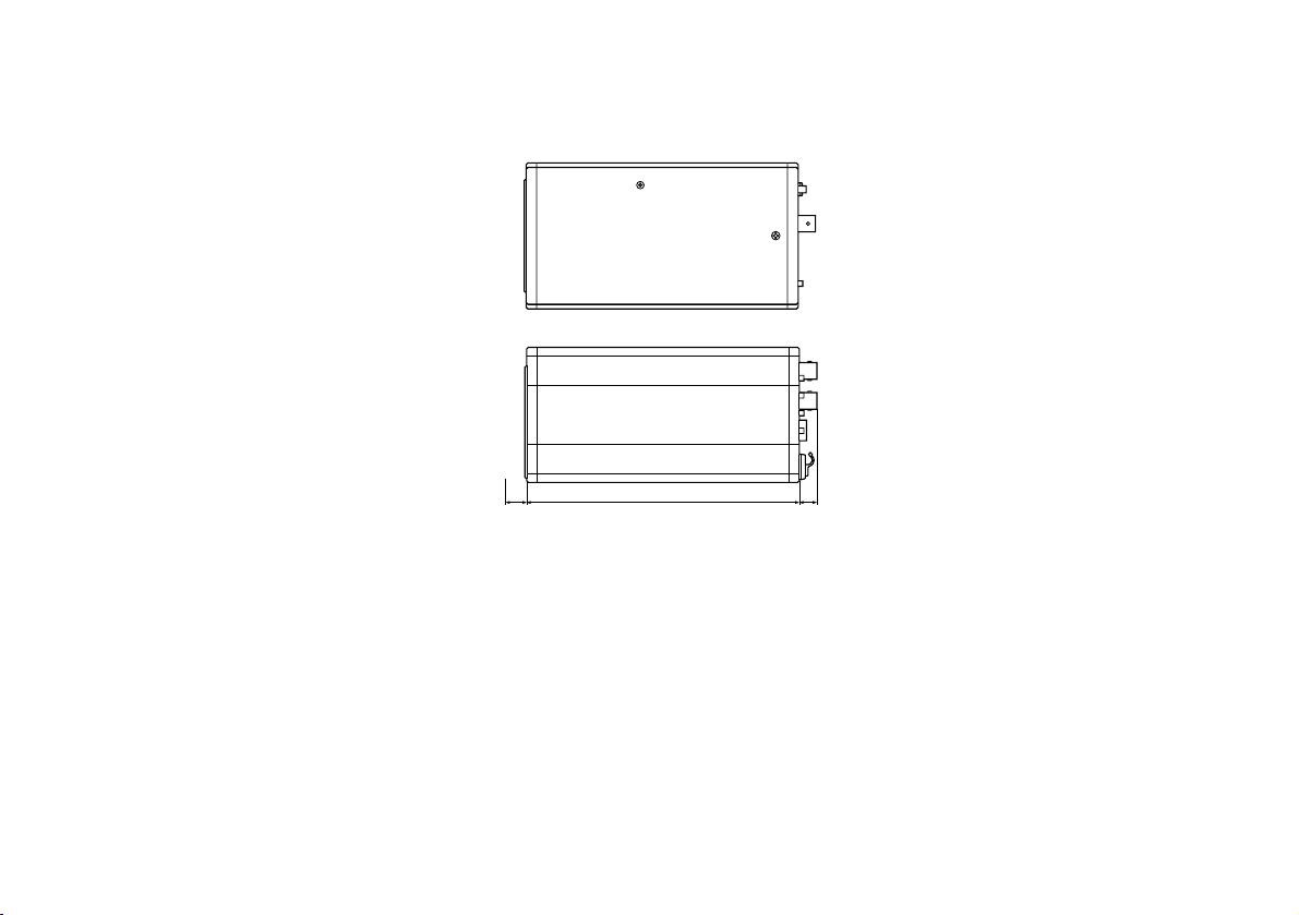
-62-
Convertible Camera AW-

-63-
(AW-E350)
FOCUS
LOCK
Convertible Camera AW-
MENU
OPTION CARD
VIDEO OUT
I / F REMOTE
G / LIN
IRIS
DC12V IN
ITEM / AWC
YES / ABC
NO / BAR
5-11/16" (145)3/64" (1) 25/64" (10)
3-5/16" (84)
3-1/32" (77)
Unit: inch (mm)

-64-
SPECIFICATIONS
Source Voltage: DC 12 V Power consumption: 12.6 W (AW-E750), 12.0 W (AW-E655)
indicates safety information.
$
AW-E750, AW-E655
AW-E750 AW-E655
Optical system 2/3" prism, F1.4 1/2" prism, F1.4
Pick up device 2/3" interline-type CCD 1/2" interline-type CCD
Number of valid pixels 768 x 494 (approx. 380,000 pixels)
Total number of pixels 811 x 508 (approx. 410,000 pixels)
Scanning system 525 scanning lines, 60 fields, 30 frames
Synchronizing system
Internal synchronization: EIA standard;
external synchronization: BBS or VBS (BNC x 1, D-sub 50P x 1)
Composite: 1.0 Vp-p/75 ohms (BNC x 1, D-sub 50 P x 1)
Video output
Y/C Y: 1.0 Vp-p/75 ohms; C: 0.286 Vp-p/75 ohms (burst) (D-sub 50P x 1)
Y/Pr/Pb Y: 1 Vp-p/75 ohms; Pr, Pb: 0.7 Vp-p/75 ohms (D-sub 50P x 1)
RGB G: 1 Vp-p/75 ohms; RB: 0.7 Vp-p/75 ohms (D-sub 50P x 1)
Standard illumination,
2,000 lx (F14, 3,200K)
color temperature
Minimum illumination
0.00005 lx at F1.4, Night Eye mode, 30 dB digital gain,
2s storage time, output of 70% or above
S/N ratio 67 dB (Y signal, DTL OFF, DNR ON)
Horizontal resolution 850 TV lines (high-band DTL ON, center area)
Registration 0.05% (entire screen, excluding effects of lens)
Geometric distortion 0%
Contour correction Horizontal, vertical (2H)
White balance AWC A, AWC B (R/B gain, painting), ATW, 3,200K, 5,600K preset
Black balance Auto (R/B pedestal, painting function)
Chroma amount variability 7-level variability
Encoding system OFF, Low, High
Gain selection 0 to 30 dB in steps, AGC, Night Eye L, H

-65-
AW-E750 AW-E655
Electronic shutter speeds 1/100, 1/250, 1/500, 1/1000, 1/2000, 1/4000, 1/10000;
ELC, synchro scanner (60.34 Hz to 15.75 kHz)
CCD readout selection Field, frame1, frame2
Color bars SMPTE
Lens mount 2/3" bayonet mount 1/2" bayonet mount
Lens diaphragm Auto, Manual (but only with remote control), adjust ON, OFF
Internal filters ––– IR Through, Normal, 1/16ND, 1/64ND
MENU(A)
Selector switches
ITEM/AWC (S) (AWC: when menu screen is not displayed)
UP/ABC (+) (ABC: when menu screen is not displayed)
NO/BAR (−) (BAR: when menu screen is not displayed)
VIDEO OUT BNC connector VIDEO OUT BNC connector
G/L IN BNC connector G/L IN BNC connector
Input/output connectors
IRIS 12P round connector IRIS 12P round connector
DC 12V IN DC connector DC 12V IN DC connector
I/F REMOTE 50P D-sub connector I/F REMOTE 50P D-sub connector
ZOOM/FOCUS 12P round connector
Indicator Red LED; power ON when lighted
For storage: –20°C to +60°C
Allowable temperature ranges For guaranteeing performance: +5°C to +35°C
For guaranteeing operation: –10°C to +45°C
Allowable humidity ranges
For storage: 20% to 90%
For operation: 20% to 90%
Dimensions (W x H x D)
3-5/16"x3-3/4"x7-9/16" (84x95x192 mm) 3-5/16"x4-1/2"x7-3/16"(84x114x182
mm)
Weight
2.4 lbs (1.1 kg) 2.6 lbs (1.2 kg)

-66-
Source Voltage: DC 12 V Power consumption: 11.8 W (AW-E650), 11.3 W (AW-E350)
indicates safety information.
$
AW-E650, AW-E350
AW-E650 AW-E350
Optical system 1/2" prism, F1.4 1/3" prism, F1.4
Pick up device 1/2" interline-type CCD 1/3" interline-type CCD
Number of valid pixels 768 x 494 (approx. 380,000 pixels)
Total number of pixels 811 x 508 (approx. 410,000 pixels)
Scanning system 525 scanning lines, 60 fields, 30 frames
Synchronizing system
Internal synchronization: EIA standard;
external synchronization: BBS or VBS (BNC x 1, D-sub 50P x 1)
Composite: 1.0 Vp-p/75 ohms (BNC x 1, D-sub 50 P x 1)
Video output
Y/C Y: 1.0 Vp-p/75 ohms; C: 0.286 Vp-p/75 ohms (burst) (D-sub 50P x 1)
Y/Pr/Pb Y: 1 Vp-p/75 ohms; Pr, Pb: 0.7 Vp-p/75 ohms (D-sub 50P x 1)
RGB G: 1 Vp-p/75 ohms; RB: 0.7 Vp-p/75 ohms (D-sub 50P x 1)
Standard illumination, 2,000 lx 2,000 lx
color temperature (F14, 3,200K) (F9.5, 3,200K)
0.00005 lx at F1.4, 0.00015 lx at F1.4,
Minimum illumination Night Eye mode, 30 dB digital gain, Night Eye mode, 30 dB digital gain,
2s storage time, output of 70% or above 2s storage time, output of 70% or above
S/N ratio 67 dB (Y signal, DTL OFF, DNR ON) 66 dB (Y signal, DTL OFF, DNR ON)
Horizontal resolution 850 TV lines (high-band DTL ON, center area)
Registration 0.05% (entire screen, excluding effects of lens)
Geometric distortion 0%
Contour correction Horizontal, vertical (2H)
White balance AWC A, AWC B (R/B gain, painting), ATW, 3,200K, 5,600K preset
Black balance Auto (R/B pedestal, painting function)
Chroma amount variability 7-level variability
Encoding system OFF, Low, High
Gain selection 0 to 30 dB in steps, AGC, Night Eye L, H 0 to 30 dB in steps, AGC, Night Eye

-67-
Weight and Dimensions indicated above are approximate.
Specifications are subject to change without notice.
AW-E650 AW-E350
Electronic shutter speeds
1/100, 1/250, 1/500, 1/1000, 1/2000, 1/4000, 1/10000;
ELC, synchro scanner (60.34 Hz to 15.75 kHz)
CCD readout selection Field, frame1, frame2
Color bars SMPTE
Lens mount 1/2" bayonet mount 1/3" C mount
Lens diaphragm Auto, Manual (but only with remote control), adjust ON, OFF
Internal filters IR Through, Normal, 1/16ND, 1/64ND –––
MENU(A)
Selector switches
ITEM/AWC (S) (AWC: when menu screen is not displayed)
UP/ABC (+) (ABC: when menu screen is not displayed)
NO/BAR (−) (BAR: when menu screen is not displayed)
VIDEO OUT BNC connector
G/L IN BNC connector
Input/output connectors IRIS 12P round connector
DC 12V IN DC connector
I/F REMOTE 50P D-sub connector
Indicator Red LED; power ON when lighted
For storage: –20°C to +60°C
Allowable temperature ranges For guaranteeing performance: +5°C to +35°C
For guaranteeing operation: –10°C to +45°C
Allowable humidity ranges
For storage: 20% to 90%
For operation: 20% to 90%
Dimensions (W x H x D)
3-5/16"x3-1/32"x6-15/16" (
84 x 77 x 177 mm)
3-5/16"x3-1/32"x6-1/8" (
84 x 77 x 156 mm)
Weight
2.0 lbs (
0.92 kg)
1.7 lbs (
0.77 kg)

Rubber Sheet ............................................................... 1
Mounting Adaptor ........................................................ 1
Screw ........................................................................... 2
STANDARD ACCESSORIES
Mounting Spacer
(models AW-E750, AW-E655 only) .......................... 1
-68-


PANASONIC BROADCAST & TELEVISION SYSTEMS COMPANY
UNIT COMPANY OF MATSUSHITA ELECTRIC CORPORATION OF AMERICA
Executive Office:
One Panasonic Way 4E-7, Secaucus, NJ 07094 (201) 348-7000
EASTERN ZONE:
One Panasonic Way 4E-7, Secaucus, NJ 07094 (201) 348-7621
Southeast Region:
1225 Northbrook Parkway, Ste 1-160, Suwanee, GA 30024 (770) 338-6835
Central Region:
1707 N Randall Road E1-C-1, Elgin, IL 60123 (847) 468-5200
WESTERN ZONE:
3330 Cahuenga Blvd W., Los Angeles, CA 90068 (323) 436-3500
Government Marketing Department:
52 West Gude Drive, Rockville, MD 20850 (301) 738-3840
Broadcast PARTS INFORMATION & ORDERING:
9:00 a.m. – 5:00 p.m. (EST) (800) 334-4881/24 Hr. Fax (800) 334-4880
Emergency after hour parts orders (800) 334-4881
TECHNICAL SUPPORT:
Emergency 24 Hour Service (800) 222-0741
Panasonic Canada Inc.
5770 Ambler Drive, Mississauga, Ontario L4W 2T3 (905) 624-5010
Panasonic de Mexico S.A. de C.V.
Av angel Urraza Num. 1209 Col. de Valle 03100 Mexico, D.F. (52) 1 951 2127
Panasonic Sales Company
Division of Matsushita Electric of Puerto Rico Inc.
San Gabriel Industrial Park, 65th Infantry Ave., Km. 9.5, Carolina, Puerto Rico 00630 (787) 750-4300
Printed in Japan
VQT0G71-1 F1003Y1113
D
P
 Loading...