

Panasonic AW-E300SP, AW-E300S User Manual

OPERATING INSTRUCTIONS
Before attempting to connect, operate or adjust this product, please
read these instructions completely.
1/3-inch Camera With Separate Head
Model AW- P
F
OC
U
S
L
O
C
K
2
indicates safety information.
CAUTION
RISK OF ELECTRIC SHOCK
DO NOT OPEN
CAUTION: TO REDUCE THE RISK OF ELECTRIC SHOCK,
DO NOT REMOVE COVER (OR BACK).
NO USER SERVICEABLE PARTS INSIDE.
REFER TO SERVICING TO QUALIFIED SERVICE PERSONNEL.
The lightning flash with arrowhead symbol, within an equilateral triangle,
is intended to alert the user to the presence of uninsulated “dangerous
voltage” within the product’s enclosure that may be of sufficient
magnitude to constitute a risk of electric shock to persons.
The exclamation point within an equilateral triangle is intended to alert the
user to the presence of important operating and maintenance (service)
instructions in the literature accompanying the appliance.
WARNING:
TO REDUCE THE RISK OF FIRE OR SHOCK HAZARD, DO NOT
EXPOSE THIS EQUIPMENT TO RAIN OR MOISTURE.
CAUTION:
TO REDUCE THE RISK OF FIRE OR SHOCK HAZARD AND ANNOYING
INTERFERENCE, USE THE RECOMMENDED ACCESSORIES ONLY.
FCC Note:
This device complies with Part 15 of the FCC Rules. To assure continued
compliance follow the attached installation instructions and do not make any
unauthorized modifications.
This equipment has been tested and found to comply with the limits for a class A
digital device, pursuant to Part 15 of the FCC Rules. These limits are designed to
provide reasonable protection against harmful interference when the equipment is
operated in a commercial environment. This equipment generates, uses, and can
radiate radio frequency energy and, if not installed and used in accordance with the
instruction manual, may cause harmful interference to radio communications.
Operation of this equipment in a residential area is likely to cause harmful
interference in which case the user will be required to correct the interference at his
own expense.

3
Contents
Introduction. . . . . . . . . . . . . . . . . . . . . . . 4
Features. . . . . . . . . . . . . . . . . . . . . . . . . . 4
Special Notes on Operation. . . . . . . . . . 5
Precautions . . . . . . . . . . . . . . . . . . . . . . . 6
Parts and Their Functions . . . . . . . . . . . 7
$ Main unit . . . . . . . . . . . . . . . . . . . . . . 7
$ Camera head unit . . . . . . . . . . . . . . . 9
Installation. . . . . . . . . . . . . . . . . . . . . . . 10
$ Attaching the lens . . . . . . . . . . . . . . 10
$ Installation on a camera stand
(tripod, etc.) . . . . . . . . . . . . . . . . . . . 10
System Configuration (Connections)
. . . 11
$ Connecting equipment with a
composite video input connector. . . 11
$ Connecting a remote control unit
(RCU) . . . . . . . . . . . . . . . . . . . . . . . 12
$ Connecting a remote control box
(RCB) . . . . . . . . . . . . . . . . . . . . . . . 13
$ Connecting multiple cameras
(achieving genlock) . . . . . . . . . . . . . 14
$ Connections for exercising control
from a computer . . . . . . . . . . . . . . . 15
$ Reference: Model numbers of related
equipment . . . . . . . . . . . . . . . . . . . . 16
Operating Mode Selection . . . . . . . . . . 17
$
How to select the operating mode
. . 18
Operating Procedures . . . . . . . . . . . . . 19
Adjustments . . . . . . . . . . . . . . . . . . . . . 20
$ Flange back adjustment . . . . . . . . . 20
$ White balance adjustment . . . . . . . . 21
$ Black balance adjustment . . . . . . . . 23
$ Black level (total pedestal)
adjustment. . . . . . . . . . . . . . . . . . . . 24
$ Genlock adjustment. . . . . . . . . . . . . 25
Menu Item Settings and Changes . . . . 27
$ Setting the menu items . . . . . . . . . . 27
$
Halogen light, fluorescent light and
outdoor mode sub-menu screens
. . . 29
$ User mode sub-menu screens . . . . 35
Returning to Initial Settings. . . . . . . . . 42
$ Initial settings (factory settings) . . . . 43
Outline Drawings . . . . . . . . . . . . . . . . . 45
$ Main unit . . . . . . . . . . . . . . . . . . . . . 45
$ Camera head unit . . . . . . . . . . . . . . 45
Specifications . . . . . . . . . . . . . . . . . . . . 46
$ Accessories . . . . . . . . . . . . . . . . . . . 47

4
Introduction
O Featuring digital video signal processing, this 1/3-inch 3-CCD system color camera with
its separate head achieves a high picture quality and high reliability as well as many and
varied functions despite its compact size and light weight.
O The head is separate which means that it can easily be mounted on a microscope (C
mount), for instance.
O Using a menu screen format, the camera’s shooting conditions and functions can easily
be set and changed.
O The camera can be connected to a peripheral unit such as an RCB or RCU for
expanding the capabilities of the system to suit the intended applications.
O A wide range of applications can be supported by installing optional cards.
Features
High picture quality, high reliability, many and varied functions, a compact size and
light weight achieved by incorporating digital video signal processing
O Resolution: 800 lines (high band DTL ON), S/N ratio: 62 dB (DNR ON)
O Minimum illumination: 1.5 lux (f/1.4 ‘night eye’ mode)
Many and varied functions despite compact size
O Setting of camera parameters using menu screens enabled
O Auto functions such as ATW, ELC and AGC incorporated
O CCD readout (field, frame) switching supported
The vertical resolution can be improved by switching to the frame mode, and this is
useful for capturing still images and other kinds of image processing.
O Synchro scan function provided to reduce horizontal line noise when computer screens
are shot
O Functions for controlling camera by computer incorporated
O Extension of cable (standard length of 3 meters) between head unit and main unit up to
10 meters possible
Faithful image reproduction assured by many compensation circuits
O Even areas with dark colors reproduced clearly by chroma detail enhancement
O Natural detail enhancement enabled even for dark areas by dark detail circuit
O Natural dynamic range reproduced by digital highlight chroma
O Faithful reproduction of colors enabled by digital color matrix
Full spectrum of video productions supported
O Conditions optimally suited to each application selectable from 4 operation modes
(halogen light mode, fluorescent light mode, outdoor mode and user mode)
O SMPTE color bar display provided
O Remote control enabled by RCU or RCB

5
Special Notes on Operation
O Turn the power off before connecting or disconnecting cables.
O Connection or disconnection of any studio cable, RCB cable or other cable to any unit of
equipment must be performed while power is off.
While the camera is in automatic mode:
O Shooting of bright objects in ELC operation mode may result in a smeared picture
unique to the CCD.
O The ATW function under fluorescent illumination can adversely change the white
balance.

6
Precautions
O Do not attempt to disassemble the camera, Remote Control Unit (RCU) or other units.
In order to prevent electric shock, do not remove screws or covers. There are no userserviceable parts inside.
O Do not mishandle the camera. Avoid striking, shaking, etc. The camera contains
precision components which could be damaged by improper handling or storage.
O Do not let the lens remain uncovered when the camera is not in use. If the lens is not
installed, do not leave the lens mount hole uncovered.
O Do not touch the surface of the lens or prism.
O Do not use strong or abrasive detergents when cleaning the camera body.
O Do not aim the camera toward the sun, irrespective of whether it is turned on or not.
O Do not expose the camera or Remote Control Unit (RCU) to rain or moisture, and do not
try to operate the equipment in wet conditions. Do not operate the camera or RCU if it is
wet.
O Do not operate the camera or Remote Control Unit (RCU) outdoors during a thunder
storm.
O Do not use the camera where it will be subject to high temperatures or high humidity.
O Do not leave the camera and Remote Control Unit (RCU) turned on when not in use. Do
not unnecessarily turn the camera power on and off repeatedly. Do not block the
ventilation slots.
O Refer any servicing to qualified service personnel.
O Handle the camera with care.
O Place the lens cap on the lens when the camera is not in use. If the lens is not installed,
protect the surface of the prism by placing the body cap over the lens mount hole.
O Use a mild blower or lens cleaning tissue designed for coated lenses to clean the
surface of the lens or prism if it requires cleaning.
O Use a dry cloth to clean the camera if it is dirty. If the dirt is hard to remove, use mild
detergent and wipe gently.
O Use caution when operating the camera near spot lights or bright lights, as well as any
objects and surfaces which may reflect light.
O If the camera or RCU gets wet, turn the power off immediately and have the unit
checked by an authorized service facility.
O Follow normal safety precautions to avoid personal injury.
O Use the camera in an environment where the temperature is within 14°F to 113°F
(–10°C to +45°C), and the relative humidity is within 30 % to 90 %.
O Always turn the power off when the camera is not going to be used. Operate the
camera and RCU only when there is adequate ventilation.
O Operating a wireless device that generates powerful radio waves near the camera may
adversely affect the output images.
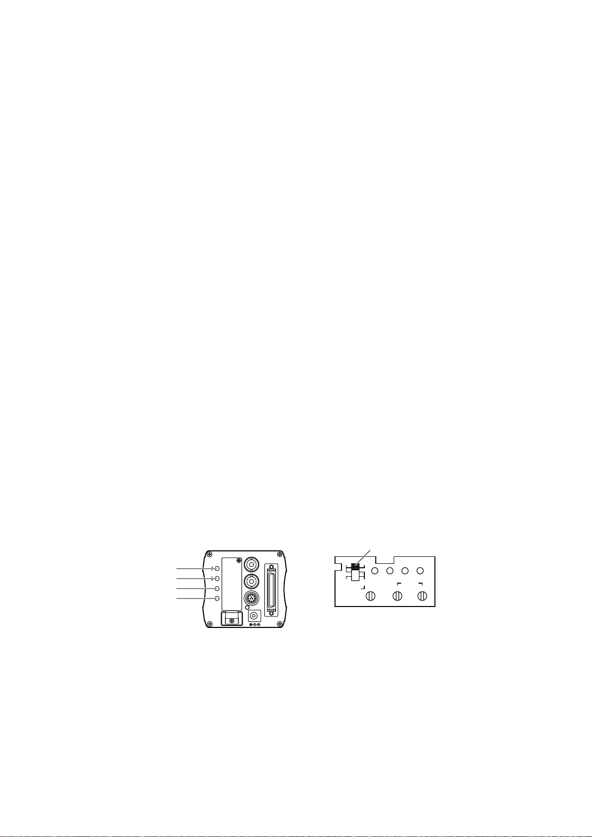
7
$ Main unit
1
OPTION CARD
MENU
ITEM / AWC
YES / ASC
+
-
NO / BAR
VIDEO OUT
G / L IN
I / F REMOTE
IRIS
DC12V IN
6=
;
2
<
8
7
9
:
3
4
5
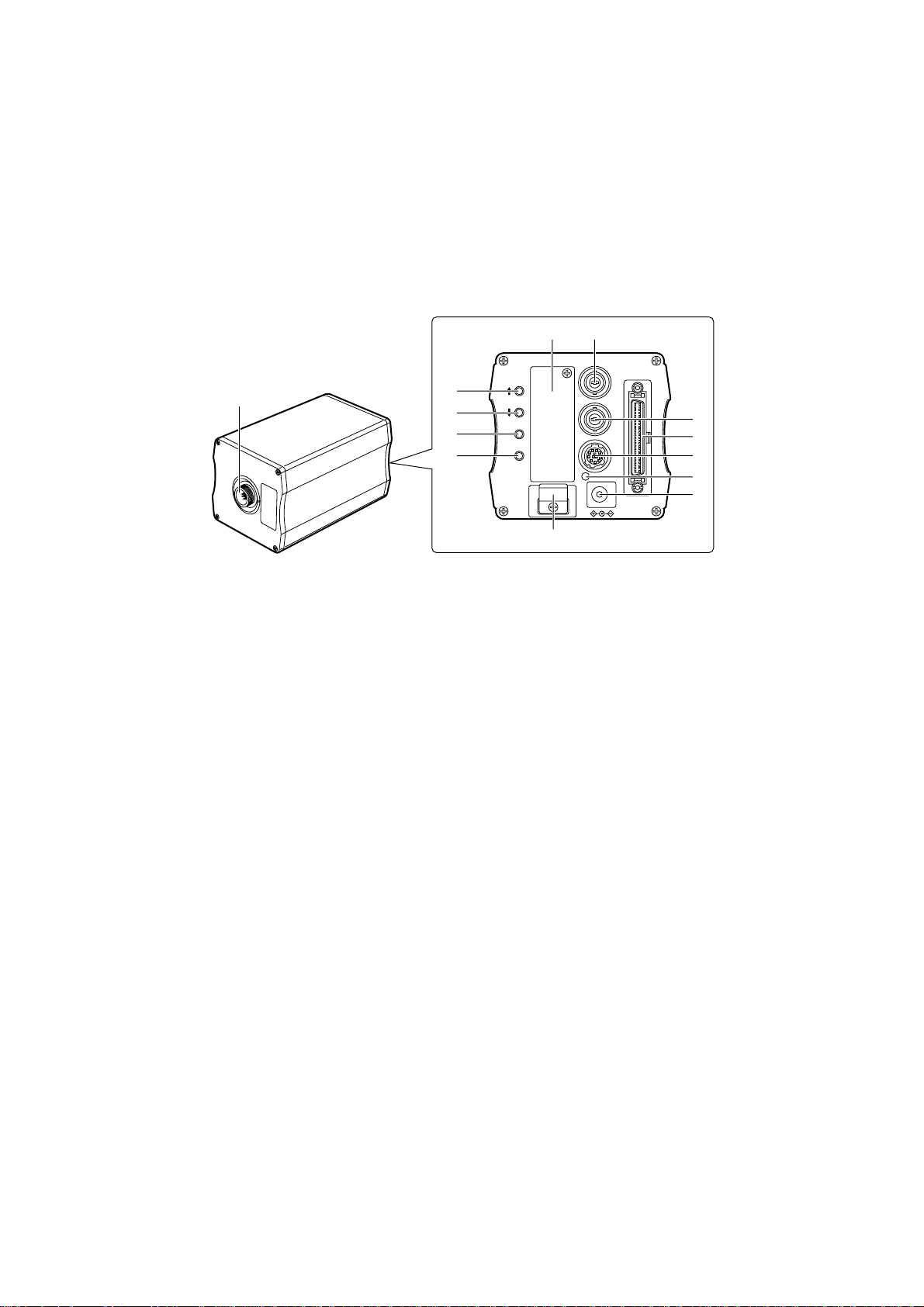
Parts and Their Functions
1Cable connector
This is used to connect the camera to the camera head unit using a cable.
2MENU switch [MENU (t)]
The menu will appear on the screen when this switch is pressed for about 5 seconds.
When it is pressed while a menu is displayed, the menu item immediately above is
selected.
3ITEM/AWC switch [ITEM/AWC (y)]
When this switch is pressed while a menu is displayed, the menu item immediately
below is selected. While a menu is not displayed (when the camera is in the shooting
mode), it serves as the automatic white balance control (AWC) switch.
4YES/ABC switch [YES/ABC (+)]
When this switch is pressed while a menu is displayed, the sub-menu of a menu item
appears on the screen. When it is pressed while a sub-menu is displayed, the higher of
the two settings shown is selected. While a menu is not displayed, it serves as the
automatic black balance control (ABC) switch.
5NO/BAR switch [NO/BAR (–)]
When this switch is pressed while the main menu is displayed, the next item down can
be selected. When it is pressed while a sub-menu is displayed, the lower of the two
settings shown is selected. When it is pressed for about 5 seconds while a menu is not
displayed, the color bar signals and camera (shooting mode) are switched.

8
Parts and Their Functions
6Video output connector [VIDEO OUT]
The composite video signals are output from this connector.
(1 V [p-p], 75 Ω, BNC connector)
7Iris connector [IRIS]
This is the standard input connector of the lens which comes with an auto iris function.
8Interface/remote connector [I/F REMOTE]
This is used to connect the remote control unit (RCU: WV-RC700A or WV-RC550),
remote control box (RCB: WV-CB700A), etc.
The AW-CA50A26 RCU cable is required to connect the WV-RC700A or WV-RC550.
The AW-CA50T10 RCB cable is required to connect the WV-CB700A.
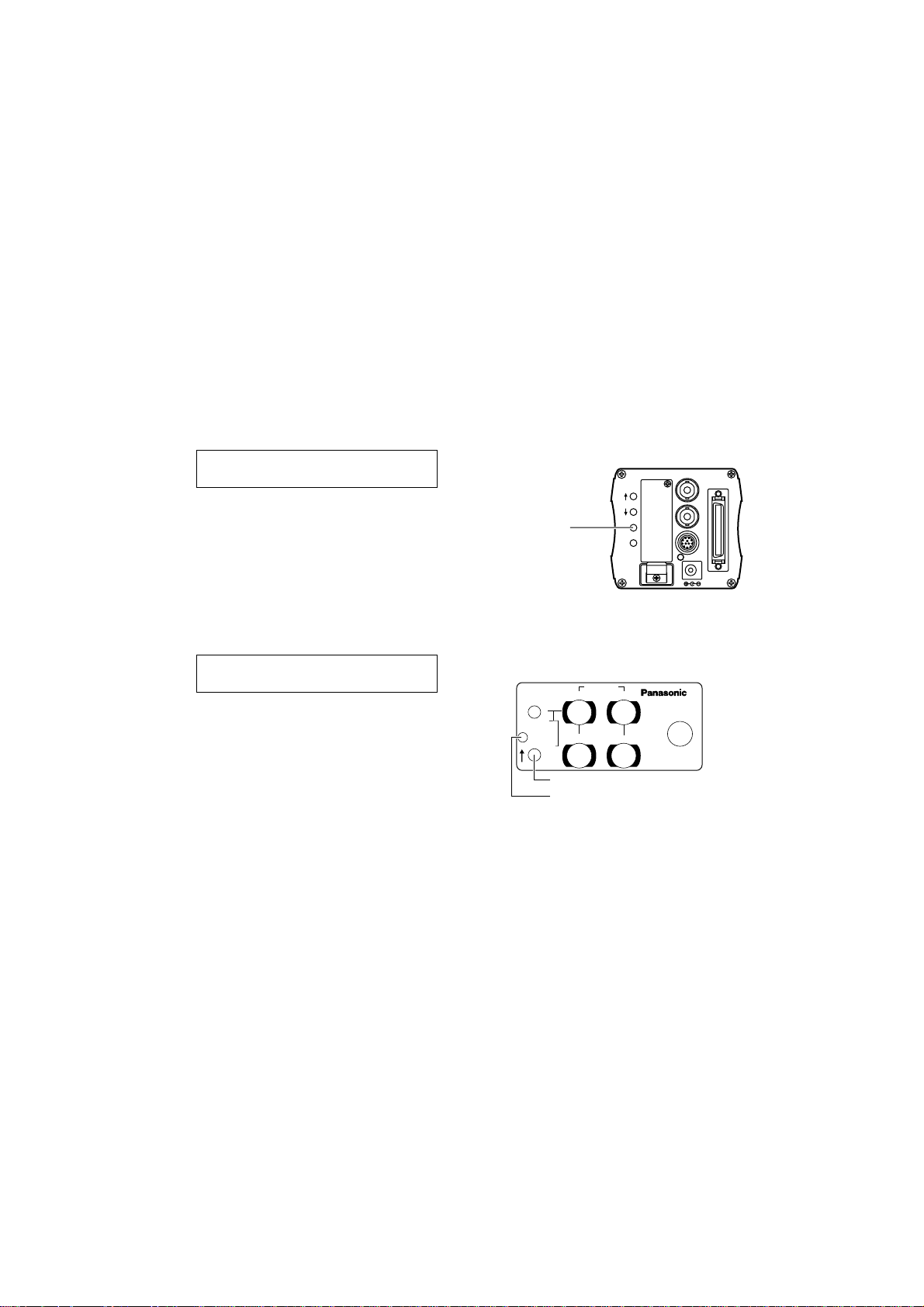
9Power LED
This lights up red when DC power is supplied to the DC 12V input socket :.
:DC 12V input socket [DC 12V IN]
The DC 12 V power supply (2 A or above) is connected here using the AW-CA4T1 DC
power cable.
;Cable clamp
This clamps the AW-CA4T1 DC power cable which has been connected to the DC 12V
input socket : to prevent the cable from becoming disconnected.
<Genlock input connector [G/L IN]
The external sync (black burst) signals are supplied to this connector to achieve genlock
with the camera.
=Option card slot
This slot is used by the option cards.
For further details, refer to the operating instructions of the option card concerned.
9
?> @
AA
FOCUS
LOCK
FO
CUS
LOCK
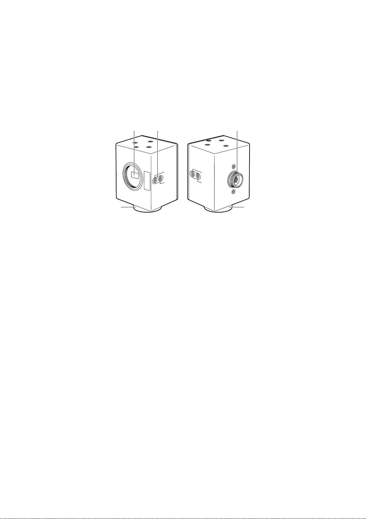
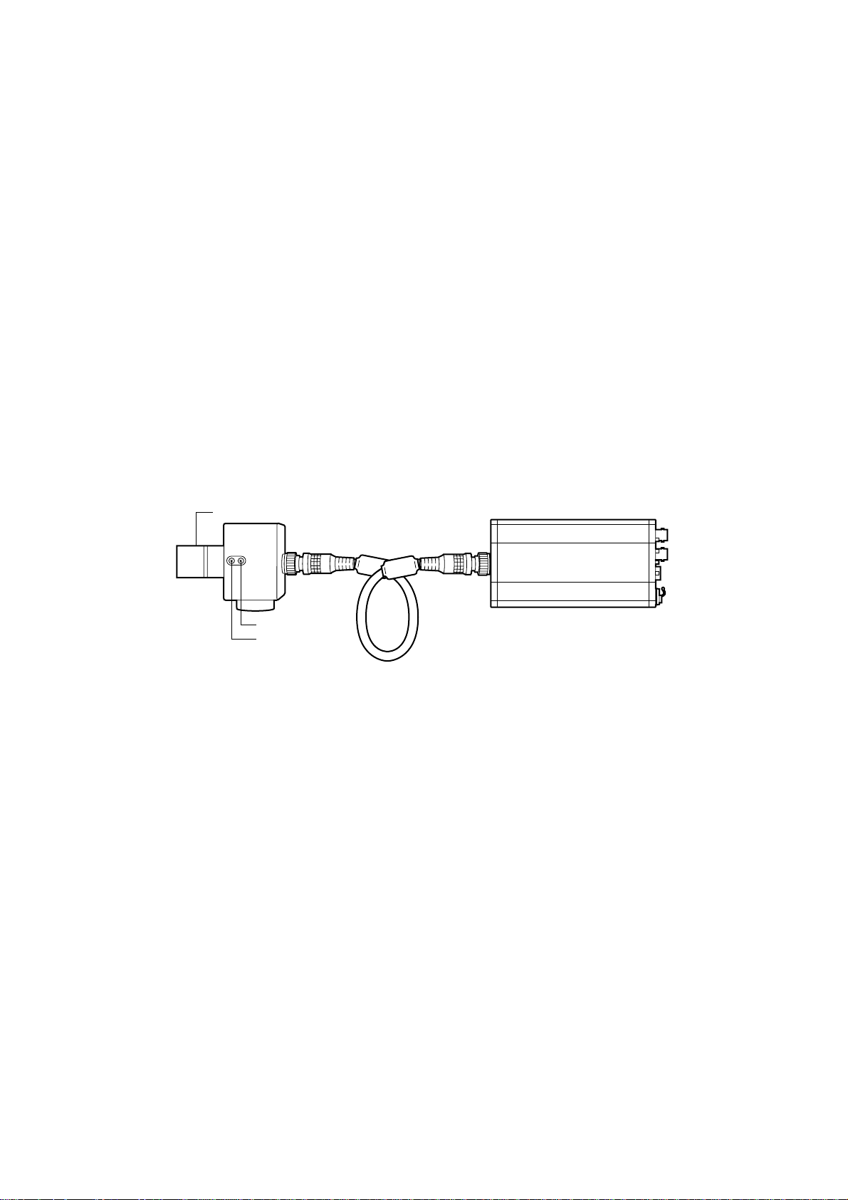
$ Camera head unit
Parts and Their Functions
>Lens mount
A 1/3-inch C mount lens or microscope adapter, etc. is attached here.
?Flange back adjust screw [FOCUS/LOCK]
When the flange back needs to be adjusted, remove the cap, loosen the LOCK screw,
and adjust by turning the FOCUS screw. (Adjustment range: ±0.2 mm)
Upon completion of the adjustment, re-tighten the LOCK screw.
@Cable connector
This is used to connect the head unit to the main unit using a cable.
ACamera mounting adapter
(mounting screw holes: M2.6a10, spring washers provided)
This is used to secure the head unit when it is to be installed on a wall or ceiling or a
tripod is to be used. The head unit can be mounted on the top or bottom surface.
10
FO
C
U
S
L
O
C
K
Less than 4.3 mm
Lens
Camera head unit
Connecting cable
Main unit
FO
C
U
S
LO
C
K
Installation
You must ask your dealer to take charge of installing, adjusting and connecting this
unit.
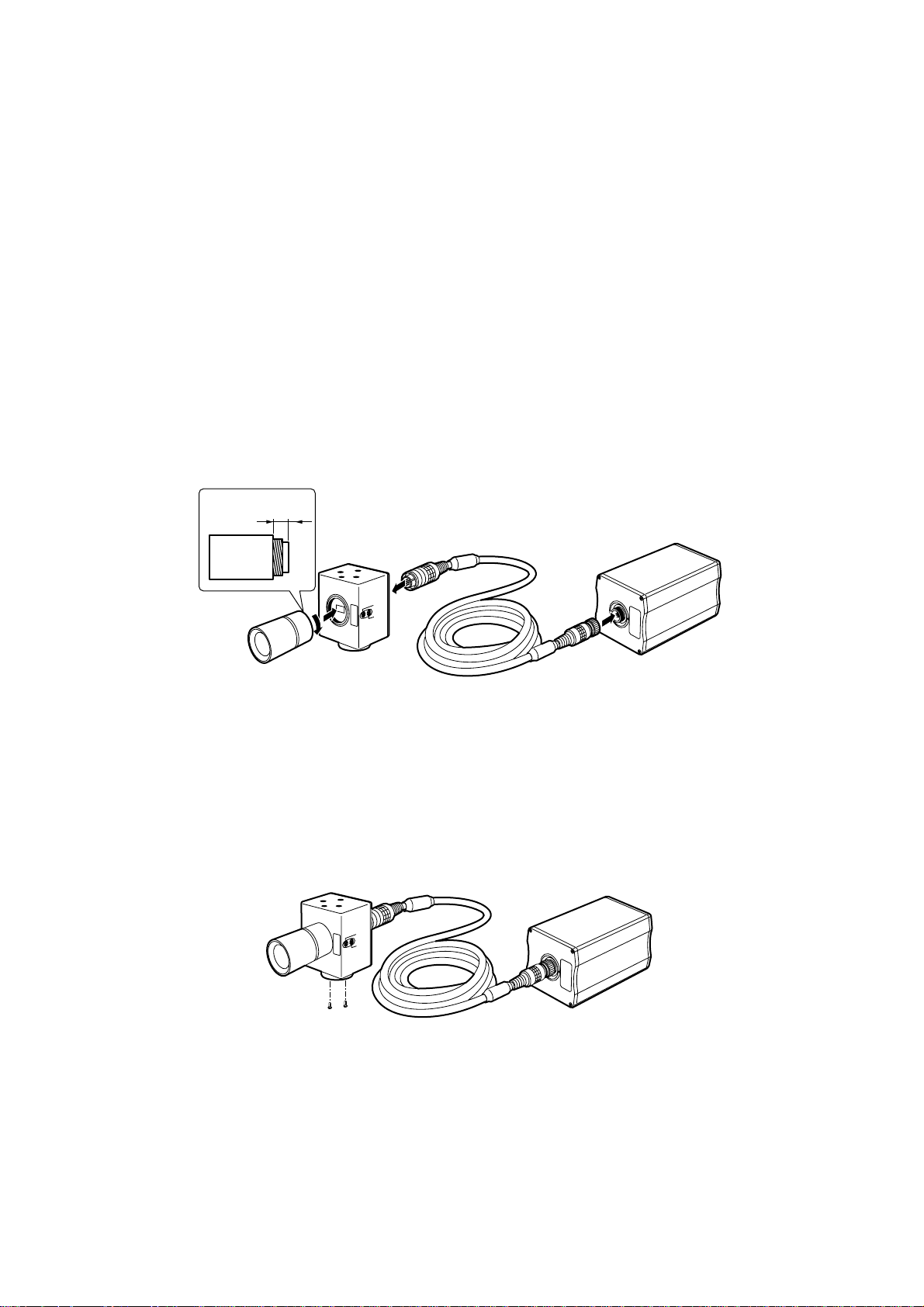
$ Attaching the lens
Remove the lens mount cap, align the lens with the thread ridges on the lens mount and
screw it firmly into place.
O A 1/3-inch C mount type of lens can be used.
Be absolutely sure that a lens whose mount threads extend no more than 4.3 mm
from the lens mount surface is used. Use of any other kind of lens may damage the
camera unit.
O Some lenses need to be attached in a different way. Therefore, reference should also
be made to the operating instructions that accompany the lens.
$ Installation on a camera stand (tripod, etc.)
1Mount the camera mounting adapter onto the top or bottom surface of the camera
head unit.
2Use the screw holes (1/4-20UNC) in the camera mounting adapter to secure the
camera stand (tripod, etc.) firmly.
Preventing the head unit from falling off or dropping
Check that the stand can adequately withstand the total weight including the weight of
the connecting cable and other parts. Use the prescribed tool to mount the head unit
securely, and be absolutely sure to take steps to prevent the camera from dropping.
11
–
+
MENU
ITEM/AWC
YES/ABC
NO/BAR
OPTION CARD
VIDEO OUT
I/F REMOTE
G/L IN
IRIS
DC12V IN
ON
POWER
OFF
POWER
O I
FUSE(POWER)
FUSE
FUSE
AC Adaptor
AW-
PS505
System Configuration (Connections)
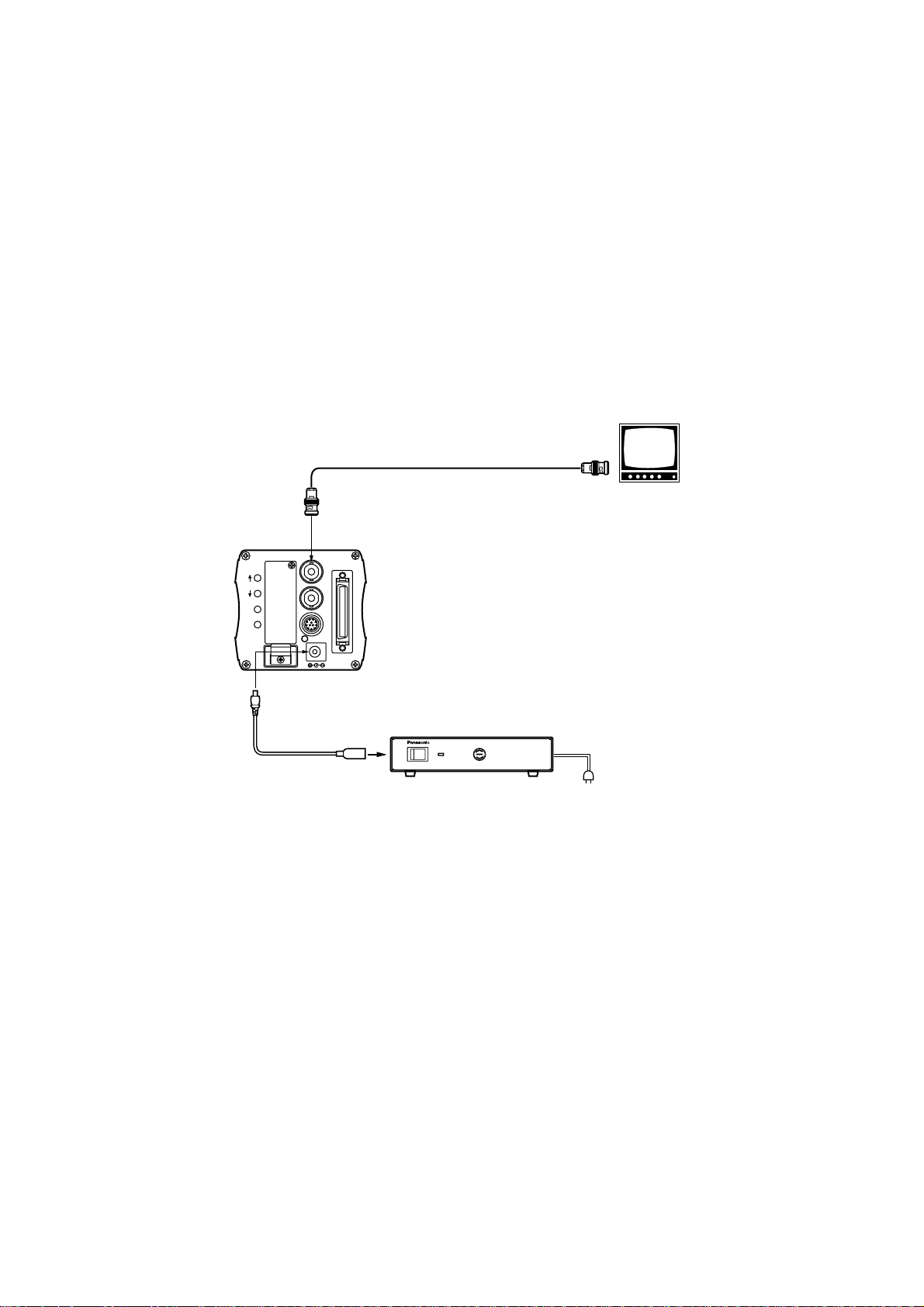
$ Connecting equipment with a composite video input
connector
O Connect the output from the camera’s video output connector to the video monitor,
VTR or other such unit which is provided with a composite video input connector.
O Use the AW-PS505 AC adapter for the power supply.
Use the AW-CA4T1 as the DC power cable.
VIDEO OUT
AW-CA4T1 DC power cable
75 Ω coaxial cable
Composite video input
connector (VIDEO IN)
Video monitor
AW-PS505 AC adapter
12
GEN-LOCKINAUX
IN
AUTO
75 Ω/Hi-Z
AUTO
75 Ω/Hi-Z
R/PR /C
OUT OUT
AUDIO
SEE MANUAL
VIDEO 1
G/Y/Y VIDEO 2
B/PB /B SYNC
S-VIDEO
14
23
TALLY
CAMERA (MULTI)
CABLE SELECT
FUSE
250V 1.25A
TALK
INCOM
RECEIVE
CONTROL
TALLY & INCOM
MULTI OVP
MPX
MPX
OUTPUT
–
+
MENU
ITEM/AWC
YES/ABC
NO/BAR
OPTION CARD
VIDEO OUT
I/F REMOTE
G/L IN
IRIS
DC12V IN
System Configuration (Connections)
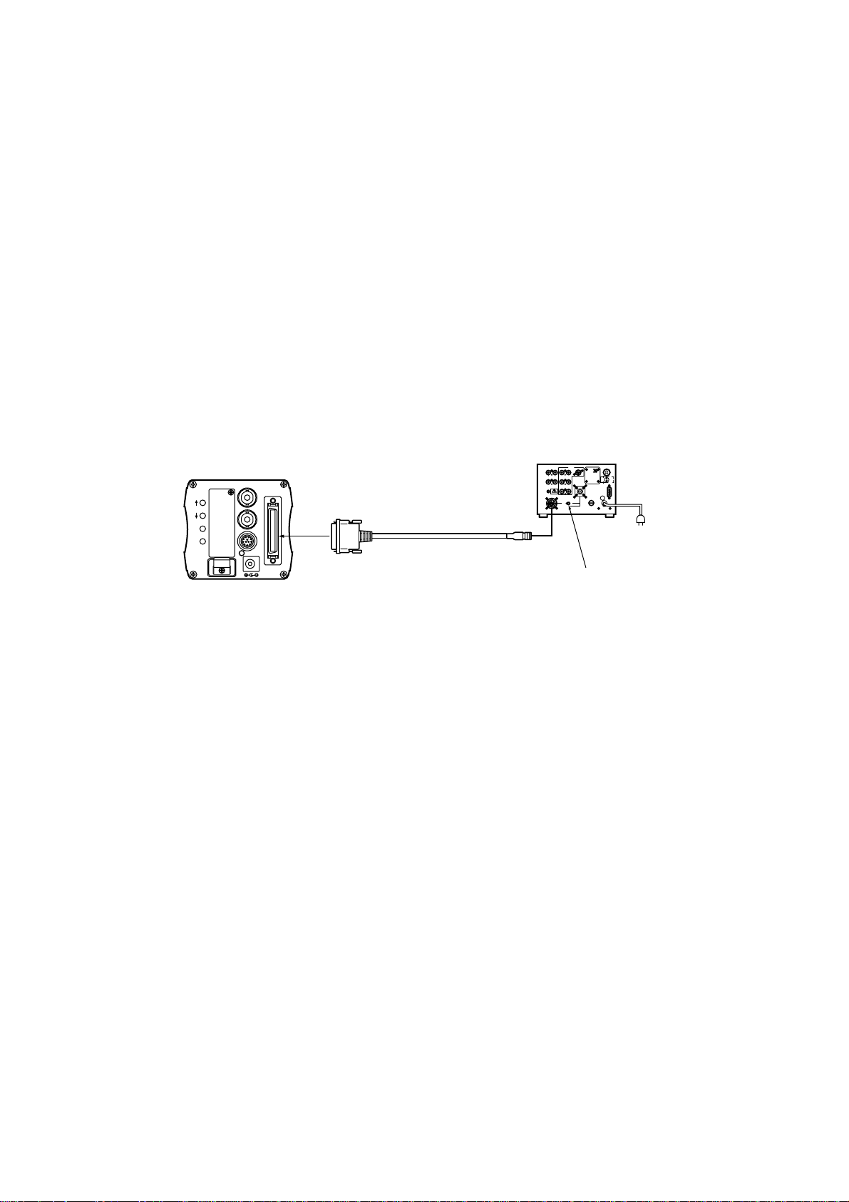
$ Connecting a remote control unit (RCU)
O Use the AW-CA50A26 RCU cable to connect the RCU (WV-RC700A or WV-RC550)
and the camera.
O The distance between the WV-RC700A and the camera can be extended up to a
maximum of 300 meters.
The distance between the WV-RC550 and the camera can be extended up to a
maximum of 100 meters.
Use the WV-CA26U15 (15 meters), WV-CA26U30 (30 meters) and WV-CA26U100
(100 meters) studio cables and the WV-CA26T26 cable joint adapter for extension.
O The power for the camera is supplied from the RCU.
1Before proceeding to connect the RCU to the camera, set the RCU’s power switch to
OFF.
2If the WV-RC700A is to be used, set the cable selector switch on the RCU to MULTI.
3Connect the 50-pin end of the RCU cable to the interface/remote connector on the
camera, and connect the 26-pin end to the RCU.
4When the RCU’s power is set to ON, the camera’s power LED lights up, and the
camera is controlled from the RCU.
Set the cable selector
switch to MULTI.
AW-CA50A26 RCU cable
(15 meters)
RCU WV-RC700A
13
–
+
MENU
ITEM/AWC
YES/ABC
NO/BAR
OPTION CARD
VIDEO OUT
I/F REMOTE
G/L IN
IRIS
DC12V IN
ALL 1
2
USER SET
ON
POWER
OFF
POWER
O I
FUSE(POWER)
FUSE
FUSE
AC Adaptor
AW-
PS505
System Configuration (Connections)
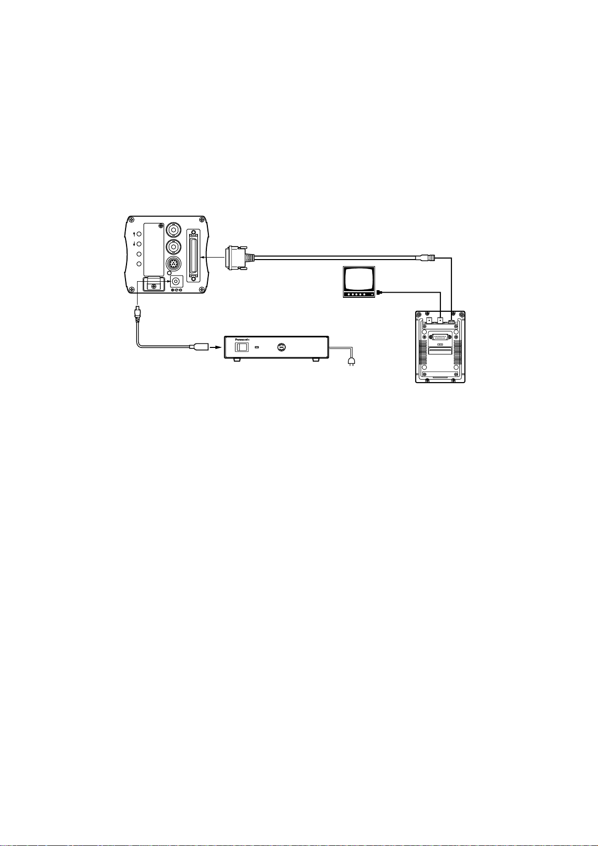
$ Connecting a remote control box (RCB)
O Use the AW-CA50T10 RCB cable to connect the RCB (WV-CB700A) and the camera.
1Before proceeding with the connections, set the AC adapter’s power switch to OFF
and the RCB ON/OFF switch on the RCB panel to OFF.
2Connect the 50-pin end of the RCB cable to the interface/remote connector on the
camera, and connect the 10-pin end to the RCB.
3Once the AC adapter’s power switch is set to ON and the RCB ON/OFF switch is set
to ON, the camera can be controlled from the RCB.
4Upon completion of shooting, first set the RCB ON/OFF switch to OFF and then set
the AC adapter’s power switch to OFF.
<Notes>
O The camera’s setting will not be stored in the memory if the AC adapter’s power switch
is set to OFF before the RCB ON/OFF switch is set to OFF.
O Since use of a cable which is too long causes a deterioration in the RCB’s monitor
output due to attenuation, this output should be used only for monitoring (verification)
purposes.
O Genlock input signals cannot be supplied from the RCB.
AW-CA50T10 RCB cable
(3 meters)
AW-CA4T1
DC power cable
Video monitor
RCB WV-CB700A
Video signal IN
connector
RCB
AW-PS505 AC adapter
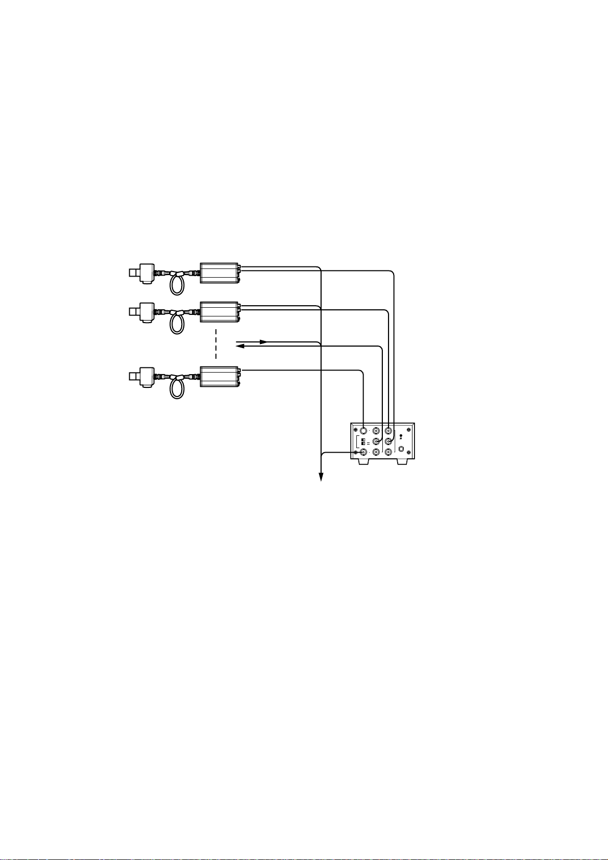
14
Camera
Camera (or special effects
unit) used to achieve genlock
VIDEO OUT
G/L IN
VIDEO OUT
INPUT
Video output
To special effects unit or monitoring
system
Genlock signal (BB)
OUTPUT
WJ-300C video
divider
System Configuration (Connections)
$ Connecting multiple cameras (achieving genlock)
O Input the sync signal (BB) to the genlock input connector.
O Do not turn off the power of the camera which is used to achieve genlock.
O The genlock adjustment must be performed when genlock is to be achieved. (See
page 25)
15
–
+
MENU
ITEM/AWC
YES/ABC
NO/BAR
OPTION CARD
VIDEO OUT
I/F REMOTE
G/L IN
IRIS
DC12V IN
ON
POWER
OFF
POWER
O I
FUSE(POWER)
FUSE
FUSE
AC Adaptor
AW-
PS505
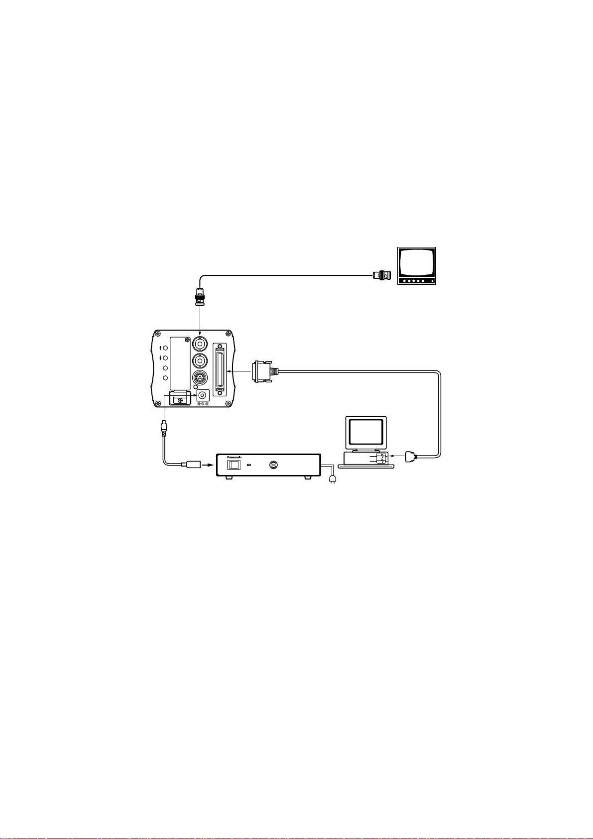
System Configuration (Connections)
$ Connections for exercising control from a computer
The AW-CA50T9 PC control cable and the dedicated software program are required for
the camera to be controlled from the computer. Ask your dealer for details.
VIDEO OUT
AW-CA4T1
DC power cable
75 Ω coaxial cable
AW-CA50T9 (10 meters) PC control cable
RS-232C
Composite video input
connector (VIDEO IN)
Video monitor
Computer
AW-PS505
AC adapter

16
System Configuration (Connections)
$ Reference: Model numbers of related equipment
Read the operating instructions of the equipment concerned along with these
instructions.
Remote control unit:
WV-RC700A
Remote control unit:
WV-RC550
Remote control box:
WV-CB700A
RCU rack-mounting chassis:
WV-Q70
Connecting cable:
WV-CA9T5 (D-sub 9-pin—BNC, approx. 5 meters)
Studio cable:
WV-CA26U15, WV-CA26U30, WV-CA26U100
Cable joint adapter:
WV-CA26T26
RCB cable:
AW-CA50T10
RCU able:
AW-CA50A26
PC control cable:
AW-CA50T9
DC power cable:
AW-CA4T1
RGB cable:
AW-CA50T6
Studio card 1 (with RGB/YPrPb output):
AW-PB301
Studio card 2 (with no RGB/YPrPb output):
AW-PB305
RGB card:
AW-PB302
AC adapter:
AW-PS505

17
Operating Mode Selection
The user can select the camera’s functions to match the operating conditions from the four
modes which have been preset. Select the mode that suits the shooting conditions and the
user’s preferences.
Halogen light mode
This mode is suited to shooting indoors at wedding receptions, parties, seminars and other
indoor events. Its settings can be changed using a simple menu.
Fluorescent light mode
This mode is suited to shooting indoors under fluorescent lighting. Its settings can be
changed using a simple menu.
Outdoor mode
This mode is suited to shooting outdoors. Its settings can be changed using a simple
menu.
User mode
This mode’s settings can be changed using a detailed menu.
18
¢¢
Use Mode Set¢
¢¢
Halogen
Fluorescent
Outdoor
User
R B
R B
PED
TOTAL
PED
A
B
ATW
AWC
AUTO
HOLD
ABC
IRIS
MAN
AUTO
1000
S/S
ELC
500
100
OFF
SHUTTER SCENE
21
3
USER
SET
AUTO/ATW
PAINTING
GAIN
Operating Mode Selection
$ How to select the operating
mode
O Operations using the camera by itself
1When the camera’s power is turned
on while the MENU switch is held
down, the Use Mode Set screen
appears on the monitor.
2Each time the MENU switch,
ITEM/AWC switch or NO/BAR switch
is pressed, the flashing operating
mode changes. Make the desired
operating mode flash by pressing of
these switches.
3When the YES/ABC switch is
pressed, the flashing item is set, and
the setting screen appears for about 5
seconds, after which the shooting
mode is restored. After this, the
camera will operate the mode which
has been set.
O Operations using the RCU or RCB
The operating mode can be selected using the scene file switch on the RCU or RCB.
Operating mode
RCU (RCB)
scene file switch
Camera
–
+
MENU
ITEM/AWC
YES/ABC
NO/BAR
OPTION CARD
VIDEO OUT
I/F REMOTE
G/L IN
IRIS
DC12V IN
MENU switch
ITEM/AWC switch
YES/ABC switch
NO/BAR switch
RCU (RCB)
Scene file switch
Halogen light mode 1
Fluorescent light mode 2
Outdoor mode 3
User mode USER SET

19
Operating Procedures
1. Turn on the power to the units concerned.
2. Adjust the subject brightness to the appropriate level.
3. Select the operating mode.
Once this mode is selected, it need not be changed so long as the camera is to be
used under the same conditions.
4. Adjust the flange back of the lens, and adjust the iris and focus.
O This adjustment must be performed when using the camera for the first time or
when the lens has been changed.
5. Adjust the white balance.
O This adjustment must be performed when using the camera for the first time or
when the camera has not been used for a prolonged period.
O It must be performed when the lighting conditions or brightness has changed.
O Once this adjustment has been performed, it need not be repeated so long as the
camera is to be used under the same conditions.
6. Adjust the black balance.
O This adjustment must be performed when using the camera for the first time or
when the camera has not been used for a prolonged period.
O It must be performed when the ambient temperature has changed significantly or at
the turning of the seasons.
O Once this adjustment has been performed, it need not be repeated so long as the
camera is to be used under the same conditions.
7. Start shooting.
Upon completion of shooting, turn off the power to the units concerned.
8. To change the camera’s settings to match other applications or conditions, refer
to page 27 and following.
The settings performed when the camera was shipped are appropriate for most
situations.
20
Focus ring
LOCK screw
FOCUS screw
Adjustments
$ Flange back adjustment
This adjustment will bring the subject into focus across the whole range from the
maximum telephoto position to the widest angle position of the zoom lens.
Perform this adjustment when back focusing is not achieved with a fixed focus lens.
(Adjustment range: ±0.2 mm)
1Shoot a dark subject to open the iris.
2Reduce the distance between the camera and subject to less than 2 meters, remove
the cap over the camera’s flange back adjust screw, and loosen the LOCK screw.
3Set the lens to the maximum telephoto position, and bring the subject into focus using
the focus ring.
4Set the lens to the widest angle position, and turn the FOCUS screw to bring the
subject into focus.
5Repeatedly adjust the focus ring and FOCUS screw until the subject is focused within
the the zoom range. Upon completion of the adjustment, tighten up the LOCK screw.

21
R B
R B
PED
TOTAL
PED
A
B
ATW
AWC
AUTO
HOLD
ABC
AUTO/ATW
PAINTING
GAIN
Adjustments
$ White balance adjustment
Automatic adjustment (AWC: AWC A/AWC B)
O Use the camera in the AWC mode if the lighting conditions at the shooting site will
remain unchanged.
O When “AWC A” or “AWC B” has been selected for the white balance on the Color Set
sub-menu (pages 32, 38), the color temperature conditions of two locations can be
preset (stored in the memory) using A/B.
O When the camera is to be used under the same conditions as those of the settings,
simply perform the adjustment once, and set the menu or RCU (RCB) switch to A or
B. After this, there is no need to perform the adjustment again.
O When new settings are established, the previous settings will be erased from the
memory.
1Select “AWC A” or “AWC B” for the
white balance.
2Shoot a white subject (such as a white
wall or white handkerchief) to fill the
screen.
The size of the white subject must be
at least 10% of the screen, and it must
appear in the middle. Keep shiny
objects or very bright objects off the
screen.
3
The white balance can be set by
pressing the ITEM/AWC switch for at
least 2 seconds in the shooting
mode.
4The white balance can be set when
the auto set switch is set to “AWC.”
The AUTO LED flashes while the
white balance is being set.
The AUTO LED goes off to indicate
the successful completion of the
setting, and it lights to indicate a failed
setting procedure. Repeat the setting
procedure in the latter case.
When performing the adjustment
using the RCU (RCB)
When performing the adjustment
using the camera
The white area size must fill at least
10% of the screen.
Camera
–
+
MENU
ITEM/AWC
YES/ABC
NO/BAR
OPTION CARD
VIDEO OUT
I/F REMOTE
G/L IN
IRIS
DC12V IN
ITEM/AWC switch
RCU (RCB)
Auto set switch
AUTO LED
22
Adjustments
Manual adjustment
Manual adjustment can be performed only in the user
mode.
1Select “AWC A” or “AWC B” for the white balance.
2Shoot a white subject to fill the screen, and attain the
automatic white balance.
3Vary the R (red) and B (blue) gain using Painting on
the color set sub-menu, and adjust it so that the
carrier in the white area of the video signals is
minimized (or so that the white area of the image
turns white). (Perform this adjustment using an
oscilloscope or waveform monitor.)
When performing the adjustment using the
camera
After having attained the automatic white balance, adjust the R (red) and B (blue) gain
using the R and B gain controls of the RCU (RCB).
<Notes>
O The white balance may not be attained properly if the subject brightness is insufficient.
O After setting the white balance, the level is stored for a prolonged period in the
memory inside the camera even when the camera’s power is turned off. There is no
need to set it again provided that the status of the subject’s color temperature remains
unchanged. However, if the setting conditions change (if the shooting location
changes from outdoors to indoors or vice versa, for example), set the white balance
again.
O If the white balance is set when using the camera by itself, the setting for the R (red)
and B (blue) gain adjustment using Painting will return to ±0. (The Painting settings
are valid only in the user mode.)
Automatic color temperature tracking (ATW)
It is a good idea to use the camera in the ATW mode if the lighting conditions at the
shooting site are likely to change (prolonged shooting outdoors, etc.).
When “ATW” is selected as the white balance setting, compensation is provided
automatically so that the white balance is attained automatically even when the light
source or color temperature changes to ensure that the images look natural.
<Note>
The white balance may shift if there is no white on the screen.
3200 K, 5600 K presettings
When “P SET 3200K” or “P SET 5600K” is selected as the white balance setting, the
status is established in which the white balance is set at a color temperature of 3200 K
or 5600 K, respectively.
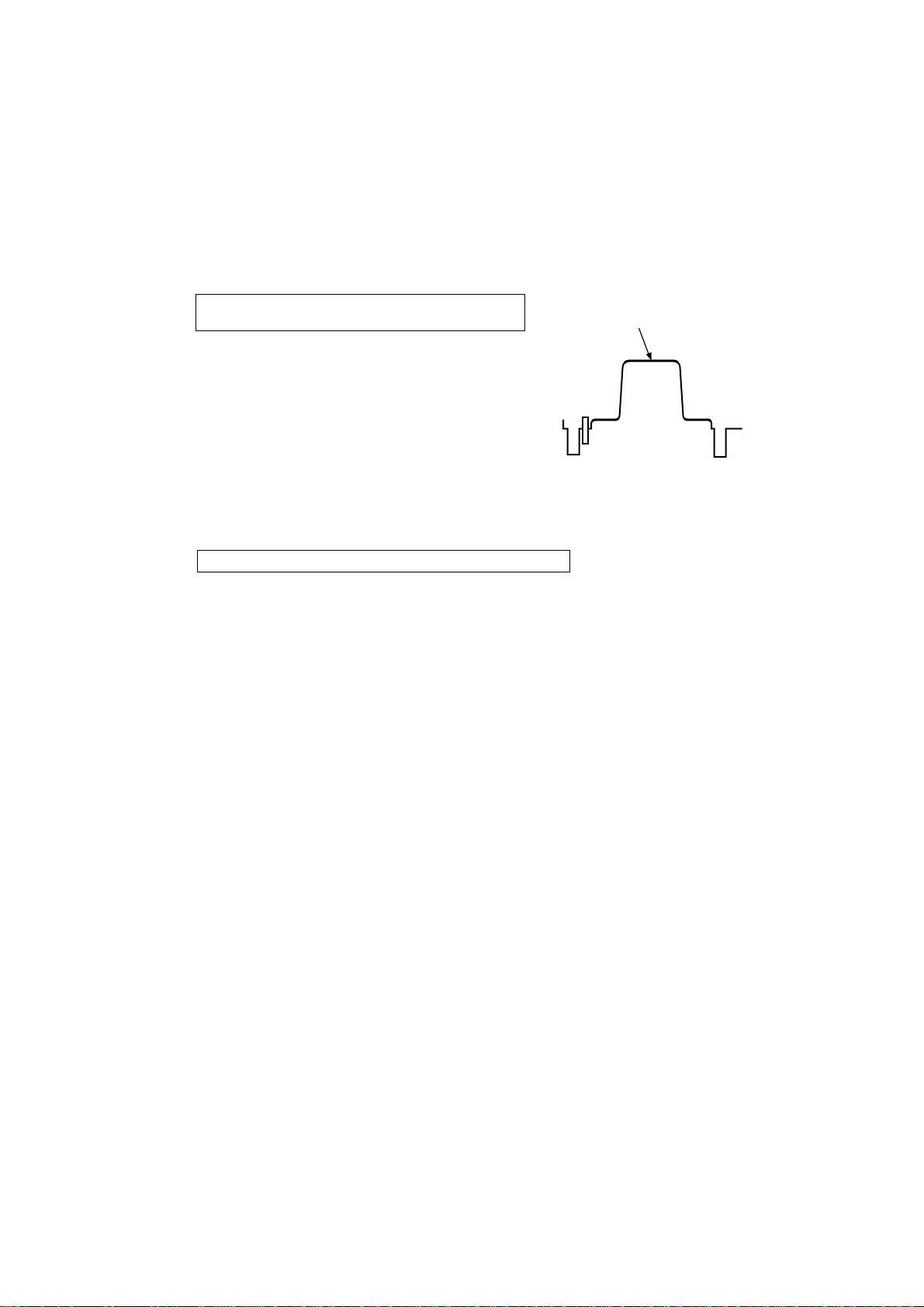
When performing the adjustment using the RCU (RCB)
Minimize the carrier.
Waveform from white
balance setting chart
23
Adjustments
$ Black balance adjustment
This adjustment is performed when using the camera for the first time, when the camera
has not been used for a prolonged period or when the lighting conditions have changed,
causing the white balance to change significantly which in turn has caused the black
balance to alter.
O Close the lens before proceeding.
O If the black balance is set when using the camera by itself, the setting for the R (red)
and B (blue) gain adjustment using Painting will return to ±0. (The Painting settings
are valid only in the user mode.)
The black balance is set in about 10
seconds when the YES/ABC switch is
held down for two or more seconds.
After the black balance has been set,
the black balance can be finely adjusted
by varying the R pedestal and B
pedestal using Painting on the color set
sub-menu in the user mode.
The black balance is set when the auto
set switch is set to “ABC.” The AUTO
LED flashes while the black balance is
being set.
The AUTO LED goes off to indicate a
successful completion of the setting, and
it lights to indicate a failed setting
procedure. Repeat the setting
procedure in the latter case.
When performing the adjustment
using the RCU (RCB)
When performing the adjustment
using the camera
R B
R B
PED
TOTAL
PED
A
B
ATW
AWC
AUTO
HOLD
ABC
AUTO/ATW
PAINTING
GAIN
RCU (RCB)
Auto set switch
AUTO LED
Camera
–
+
MENU
ITEM/AWC
YES/ABC
NO/BAR
OPTION CARD
VIDEO OUT
I/F REMOTE
G/L IN
IRIS
DC12V IN
YES/ABC switch
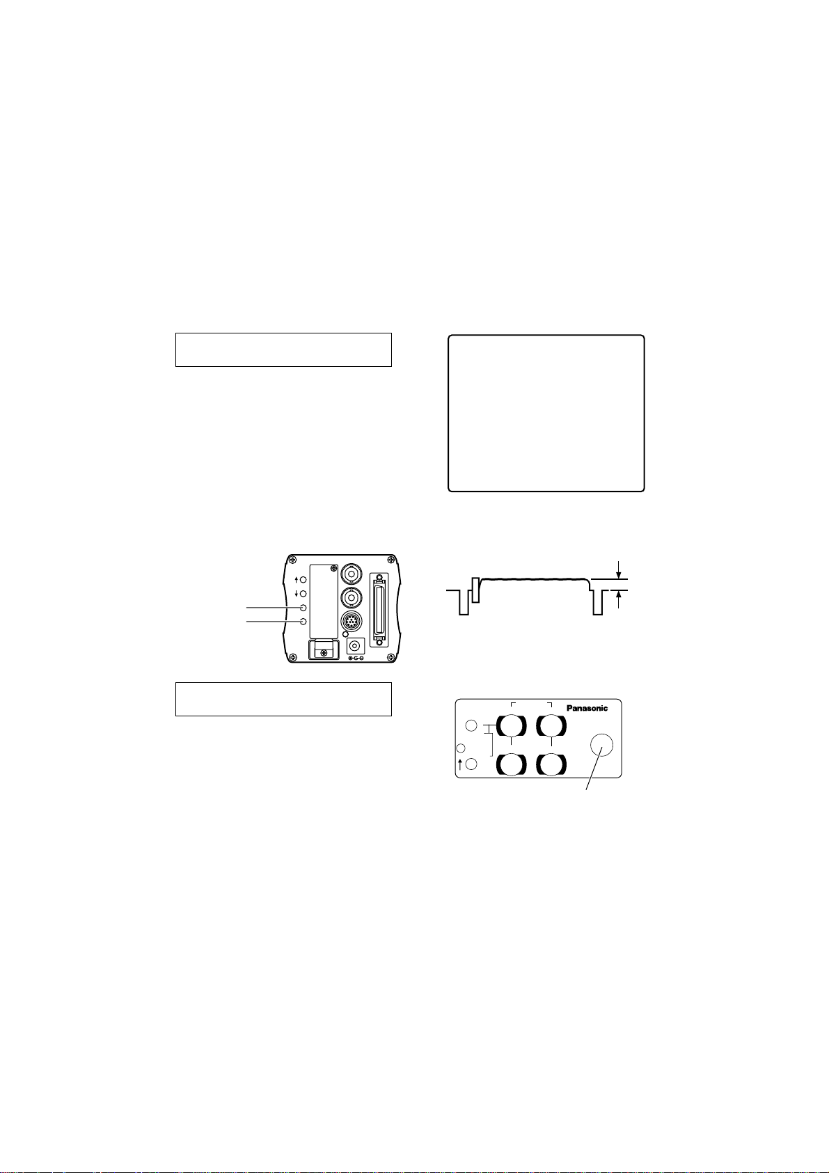
24
¢¢
Brightness Set
¢¢
Picture Level ±0
Light PEAK/AVG 0
Light Area Top cut
Auto ND (ELC) OFF
Auto Gain Up OFF
Manu Gain Up 0dB
Pedestal ±0
Contrast(Gamma) MID
Return
Adjustments
$ Black level (total pedestal) adjustment
This adjustment is performed to align the black level (pedestal level) of multiple
cameras. Ask your dealer to perform it.
(This adjustment is performed using an oscilloscope or waveform monitor.)
1Close the lens.
2Select the black level using the
brightness setting on the sub-menu
(or iris/shutter/gain settings in the user
mode).
3Adjust the black level to 5 IRE (0.035
V) using the YES/ABC switch or
NO/BAR switch.
When performing the adjustment
using the camera
Adjust the black level to 5 IRE (0.035 V)
using the total pedestal control.
When performing the adjustment
using the RCU (RCB)
Camera
–
+
MENU
ITEM/AWC
YES/ABC
NO/BAR
OPTION CARD
VIDEO OUT
I/F REMOTE
G/L IN
IRIS
DC12V IN
YES/ABC switch
NO/BAR switch
5 IRE
(0.035V)
R B
R B
PED
TOTAL
PED
A
B
ATW
AWC
AUTO
HOLD
ABC
AUTO/ATW
PAINTING
GAIN
RCU (RCB)
Total pedestal
25
¢¢
G/L. Color Bar Set
¢¢
H Phase ±0
SC Coarse 1
SC Fine ±0
Color Bar Set 7.5IRE
Return
PAGE ITEM UP DOWN
COARSE FINE
SC PHASE
270°
180°90°
0°
H.PHASE
USER SET
OFFENC
VF ON
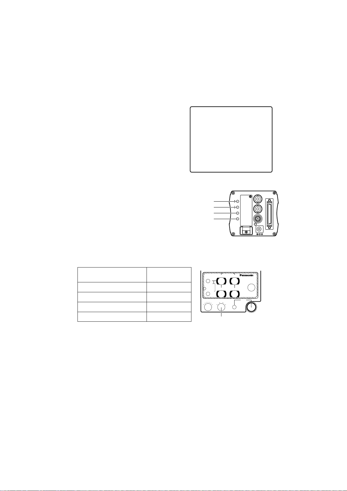
Adjustments
$ Genlock adjustment
When multiple cameras are to be used or the camera is to be used in combination with
other equipment, the phase adjustments must be performed using the camera or RCU
(RCB) in order to achieve genlock and bring the phases into alignment. Ask your dealer
to perform it.
Horizontal phase adjustment
Monitor the genlock signal input (black burst signal) and video signal output waveforms
on a dual-trace oscilloscope, and bring the horizontal phase into alignment using the
camera or RCU (RCB).
1Hold down the NO/BAR switch for at
least 5 seconds or so, and set to color
bar signals.
2Select “H phase” as the genlock/color
bar setting on the sub-menu.
3Bring the horizontal phase into
alignment using the YES/ABC switch
or NO/BAR switch.
When performing the adjustment
using the camera
Use the horizontal phase control to
perform the adjustment.
<Note>
When adjusting the horizontal phase from
the RCU (RCB), set the BAR/CAM switch
to BAR before performing the adjustment.
The horizontal phase cannot be adjusted if
this switch is set to CAM. Upon completion
of the adjustment, be absolutely sure to
return the BAR/CAM switch to CAM.
When performing the adjustment
using the RCU (RCB)
Camera
–
+
MENU
ITEM/AWC
YES/ABC
NO/BAR
OPTION CARD
VIDEO OUT
I/F REMOTE
G/L IN
IRIS
DC12V IN
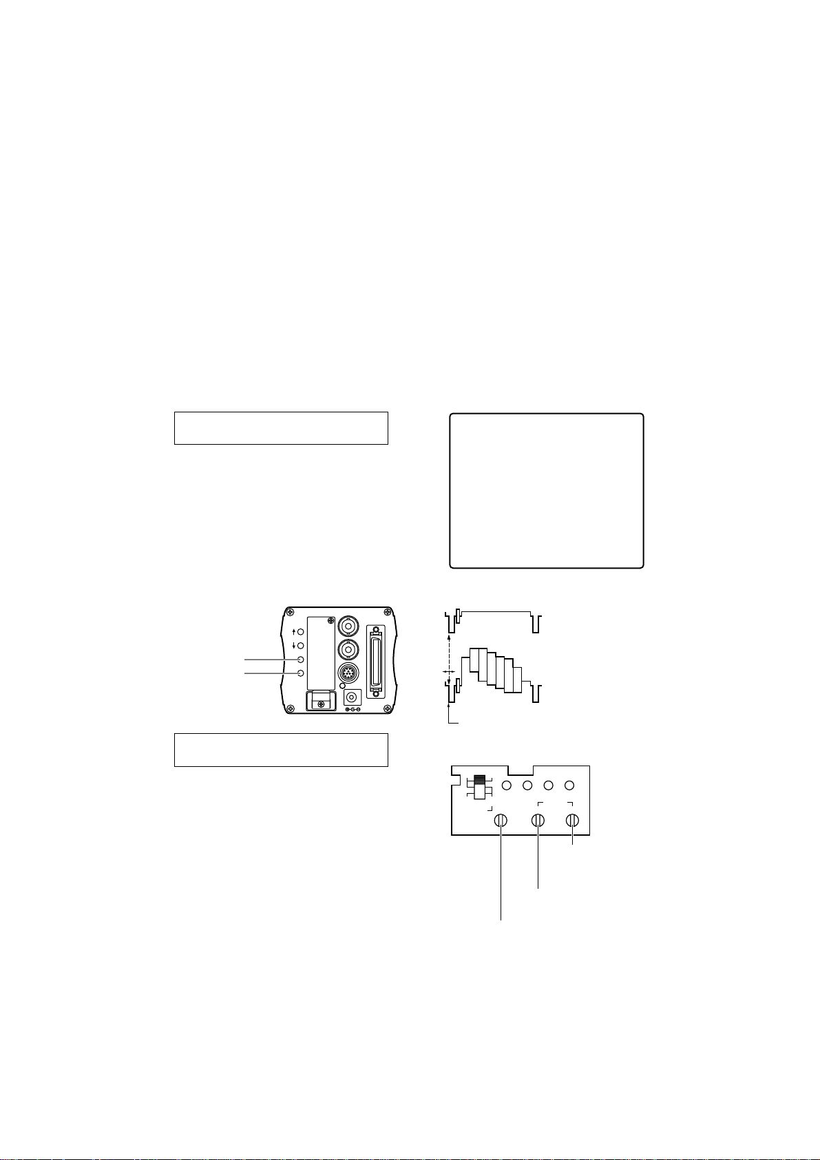
YES/ABC switch
NO/BAR switch
RCU (RCB)
Horizontal phase control
Subcarrier phase coarse
adjustment switch
Subcarrier phase fine
adjustment control
Genlock signal input
(black burst)
Video signal
Adjusting the horizontal phase
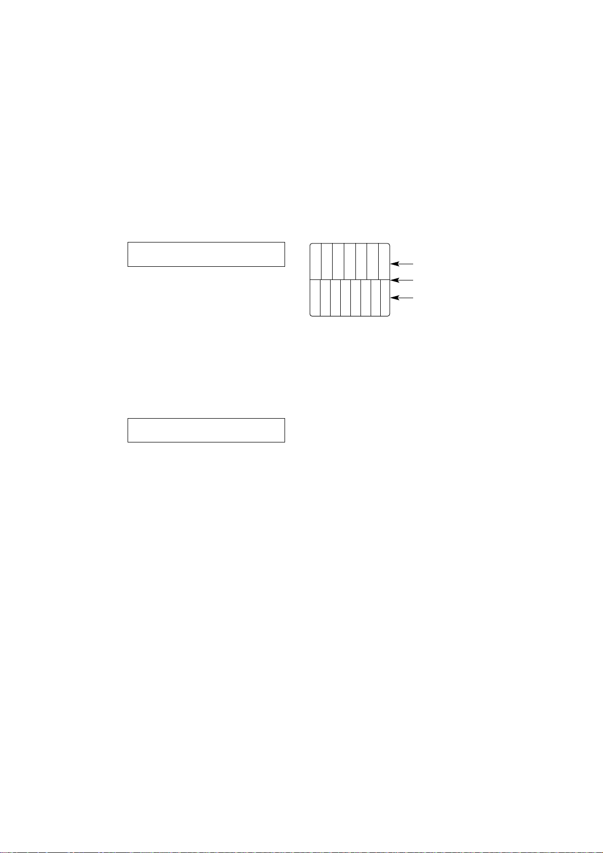
26
White
Yellow
Cyan
Green
Magenta
Red
Blue
White
Yellow
Cyan
Green
Magenta
Red
Red
Blue
Camera’s color bars
Split line
Color bars of special
effects unit
Adjustments
Color phase adjustment
Align the camera’s color phase to the reference color tones such as the program output
(color bar output which has been split) of a color special effects unit.
Adjusting the color phase with the vectorscope makes it possible to obtain an even finer
adjustment.
1Hold down the NO/BAR switch for at
least 5 seconds or so, and set to color
bar signals.
2Select “SC coarse” for the genlock
color bar setting on the sub-menu,
and use the YES/ABC switch or
NO/BAR switch to perform the coarse
adjustment.
3Select “SC fine,” and use the
YES/ABC switch or NO/BAR switch to
adjust finely so that the color phase is
brought into alignment.
When performing the adjustment
using the camera
Use the “subcarrier phase coarse adjustment switch” and “subcarrier phase fine
adjustment control” to perform the adjustment.
<Note>
When adjusting the color phase from the RCU (RCB), set the BAR/CAM switch to BAR
before performing the adjustment.
The color phase cannot be adjusted if this switch is set to CAM.
Upon completion of the adjustment, be absolutely sure to return the BAR/CAM switch to
CAM.
When performing the adjustment
using the RCU (RCB)
27
Menu Item Settings and Changes
$ Setting the menu items
O The unit’s 4 operation modes (halogen light mode, fluorescent light mode, outdoor
mode and user mode) each have a main menu.
O Each item on the main menu has a sub-menu, and each sub-menu has several
setting items.
O Although the setting items were preset to the optimum values or levels for each
operation mode before the unit was shipped, they can be changed to suit the actual
shooting conditions.
O The settings can be performed from the camera or RCU (RCB).
Setting procedure
1Settings using the camera itself
Hold down the MENU switch for at least 5 seconds.
Settings using RCU (RCB)
Set the user set switch inside the pocket to ON.
The main menu screen for the operation mode selected now appears. Refer to
page 18 for details on selecting the operation mode.
2Each time the MENU switch, ITEM/AWC switch or NO/BAR switch is pressed, the
flashing item changes.
3When the YES/ABC switch is pressed, the sub-menu screen for the flashing item
appears.
4Select the item to be set or changed using the menu screen or ITEM/AWC switch.
5Change the setting using the YES/ABC switch or NO/BAR switch.
6Select “Return” using the MENU switch or ITEM/AWC switch, and press the YES/ABC
switch. Operation now returns to the main menu.
7When the settings are completed
Settings using the camera itself
Select “End,” and press the YES/ABC switch.
Settings using RCU (RCB)
Set the user set switch inside the pocket to OFF.
The camera will now operate under these setting conditions.
Camera
–
+
MENU
ITEM/AWC
YES/ABC
NO/BAR
OPTION CARD
VIDEO OUT
I/F REMOTE
G/L IN
IRIS
DC12V IN
MENU switch
ITEM/AWC switch
YES/ABC switch
NO/BAR switch
PAGE ITEM UP DOWN
COARSE FINE
SC PHASE
270°
180°90°
0°
H.PHASE
USER SET
OFFENC
VF ON
RCU (RCB)
User set switch
28
¢¢
Halogen Mode Set
¢¢
Brightness Set
Color Set
G/L. Color Bar Set
Sharpness (DTL) Set
Other Set
Initialize Data
End
¢¢
User Mode Set
¢¢
Iris, Shutter, Gain Set
Color Set
G/L. Color Bar Set
Detail Set1 Detail Set2
Color Matrix Set
Other Set
Initialize Data
End
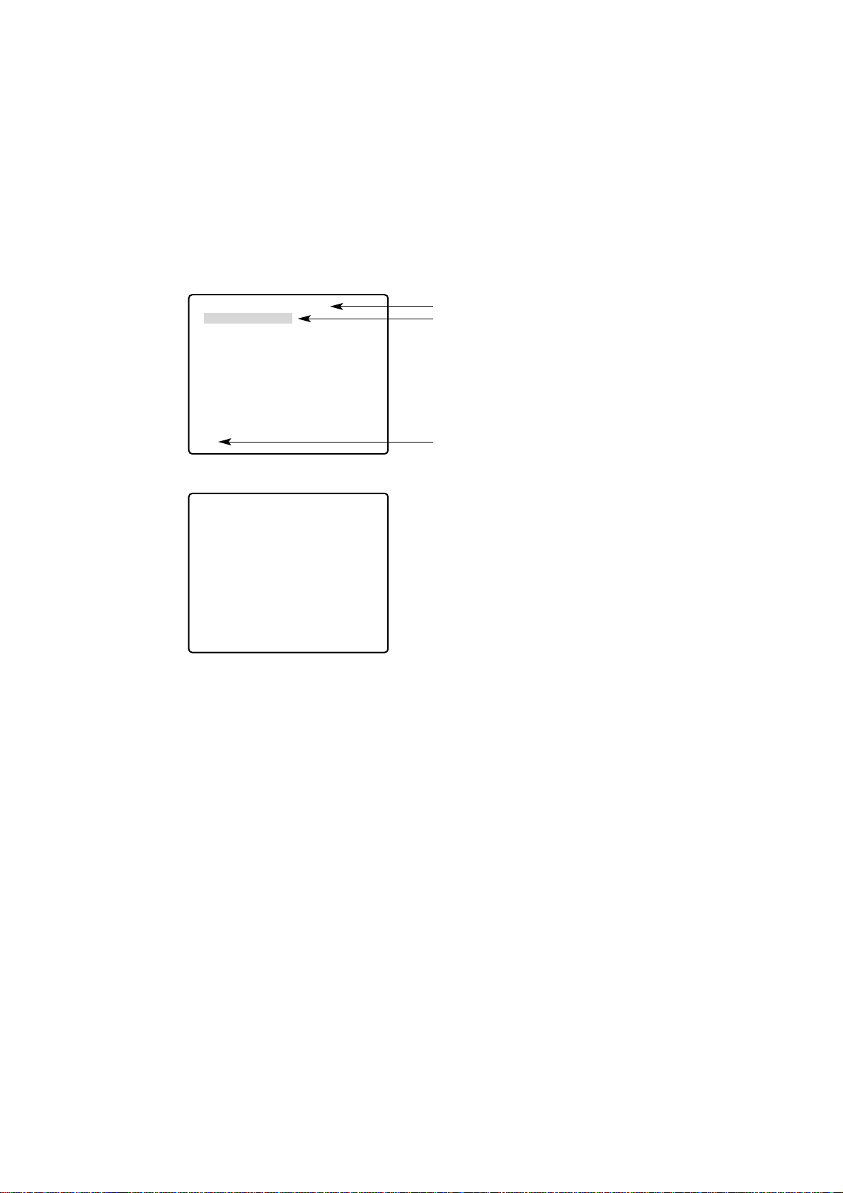
Main menu screen
Main menu for user mode
Main menus for halogen light mode, fluorescent light mode and outdoor mode
Menu Item Settings and Changes
The mode selected is displayed here.
Displayed by flashing cursor
To return to the shooting conditions (displayed when
the camera is used to perform the settings)
<Notes>
O Composite signals are supplied to the video output whether the RCU (RCB) user set
switch is at the ENC or VF position.
O “End” appears when the camera is used to perform the settings.
29
1
2
3
4
5
6
7
8
¢¢
Brightness Set
¢¢
Picture Level ±0
Light PEAK/AVG 0
Light Area Top cut
Auto ND (ELC) (OFF)
Auto Gain Up (OFF)
Manu Gain Up (0dB)
Pedestal (±0)
Contrast(Gamma) MID
Return
9
:
;
<
¢¢
Color Set
¢¢
Chroma Level ±0
Flesh Tone ±0
White Bal (AWC A)
Highlight Chroma OFF
Return
A
B
C
D
E
¢¢
Sharpness (DTL) Set
¢¢
DTL Select Sharpness
Level (HIGH)
Noise Suppress OFF
Clean DNR OFF
DTL Flesh Tone MID
Return
F
G
H
I
J
¢¢
Other Set
¢¢
Shutter Speed (OFF)
Syncro Scan --V Resolution Normal
Baud Rate 9600bps
Nega/Posi Posi
Return
=
>
?
@
¢¢
G/L. Color Bar Set
¢¢
H Phase ±0
SC Coarse (1)
SC Fine (±0)
Color Bar Set (7.5IRE)
Return
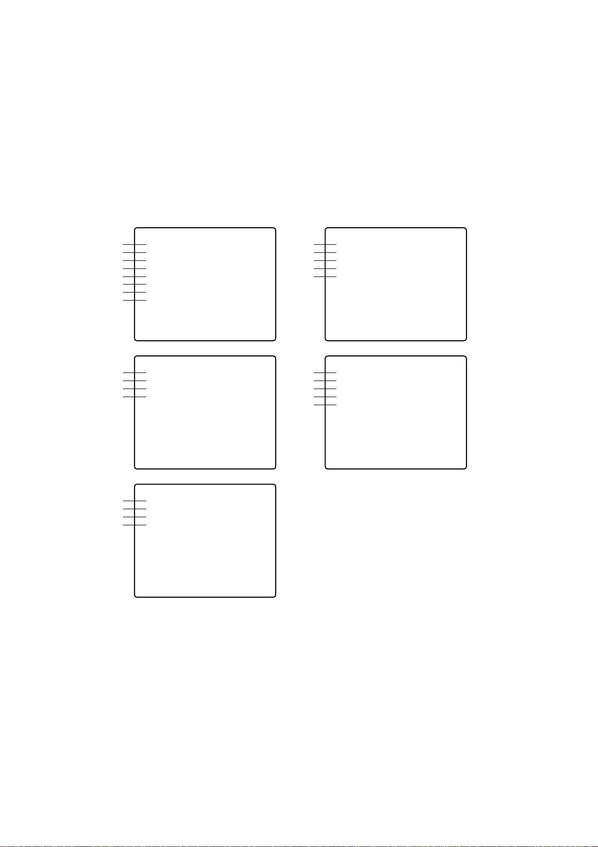
$
Halogen light, fluorescent light and outdoor mode sub-menu
screens
Menu Item Settings and Changes
(in halogen light mode, fluorescent light mode or outdoor mode)
<Notes>
O When the RCU (RCB) is used, items whose settings are enclosed in the parentheses
are set using the switches or controls on the RCU (RCB).
O To return to the initial (factory) settings, refer to page 42.
 Loading...