

Page 1
Operating Instructions
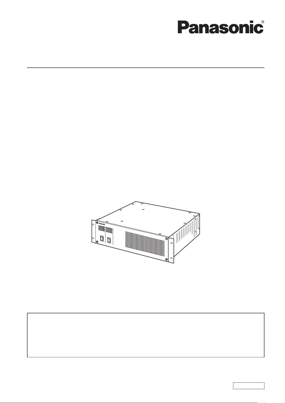
Main Frame
Model No. AV-HS60U1P
Model No. AV-HS60U2P
Model No. AV-HS60U1E
Model No. AV-HS60U2E
This manual is an excerpted version of the Operating Guide. For more information, please visit the
Panasonic website (http://pro-av.panasonic.net/en/manual/index.html), and refer to the Operating Guide
(PDF).
This manual is common to all the models.
fAV-HS60U1P/AV-HS60U2P: Single Power Supply model
fAV-HS60U1E/AV-HS60U2E: Redundant Power Supply model
Before operating this product, please read the instructions carefully and save this manual for future use.
FJ0214NN0 -YI
Printed in Japan
ENGLISH
VQT5J54
Page 2
Read this rst! (For AV-HS60U1P/AV-HS60U2P)
Read this rst!
(For AV-HS60U1P/AV-HS60U2P)
WARNING:
Installation should only be performed by qualified
installation personnel.
Improper installation may result in the entire
apparatus falling down and causing injury.
CAUTION
RISK OF ELECTRIC SHOCK
DO NOT OPEN
CAUTION: TO REDUCE THE RISK OF ELECTRIC SHOCK,
REFER TO SERVICING TO QUALIFIED SERVICE PERSONNEL.
DO NOT REMOVE COVER (OR BACK).
NO USER SERVICEABLE PARTS INSIDE.
The lightning flash with arrowhead symbol,
within an equilateral triangle, is intended to
alert the user to the presence of uninsulated
“dangerous voltage” within the product’s
enclosure that may be of sufficient magnitude
to constitute a risk of electric shock to
persons.
The exclamation point within an equilateral
triangle is intended to alert the user to
the presence of important operating and
maintenance (servicing) instructions in the
literature accompanying the appliance.
WARNING:
This equipment must be grounded.
To ensure safe operation, the three-pin plug must
be inserted only into a standard three-pin power
outlet which is effectively grounded through
normal household wiring.
Extension cords used with the equipment must
have three cores and be correctly wired to provide
connection to the ground. Wrongly wired extension
cords are a major cause of fatalities.
The fact that the equipment operates satisfactorily
does not imply that the power outlet is grounded
or that the installation is completely safe. For your
safety, if you are in any doubt about the effective
grounding of the power outlet, please consult a
qualified electrician.
WARNING:
• To reduce the risk of fire or electric shock, do not
expose this equipment to rain or moisture.
• To reduce the risk of fire or electric shock, keep
this equipment away from all liquids. Use and
store only in locations which are not exposed
to the risk of dripping or splashing liquids, and
do not place any liquid containers on top of the
equipment.
indicates safety information.
WARNING:
Always keep screws out of the reach of babies
and small children.
WARNING:
Fuse replacement should only be performed by
qualified personnel.
For continued protection against risk of fire,
replace only with the same type; 3.15 AH - 250 V
fuse for F1/F2.
CAUTION:
To reduce the risk of fire or electric shock, refer
mounting of the optional interface boards to qualified
service personnel.
CAUTION:
To reduce the risk of fire or electric shock and
annoying interference, use the recommended
accessories only.
CAUTION:
In order to maintain adequate ventilation, do
not install or place this unit in a bookcase, builtin cabinet or any other confined space. To
prevent risk of electric shock or fire hazard due to
overheating, ensure that curtains and any other
materials do not obstruct the ventilation.
CAUTION:
The mains plug of the power supply cord shall
remain readily operable.
The AC receptacle (mains socket outlet) shall
be installed near the equipment and shall be
easily accessible. To completely disconnect this
equipment from the AC mains, disconnect the
power cord plug from the AC receptacle.
CAUTION:
A coin type battery is installed inside of the unit.
Do not expose the unit to excessive heat such as
sunshine, fire or the like.
2
Page 3
Read this rst! (For AV-HS60U1P/AV-HS60U2P)
indicates safety information.
CAUTION:
This apparatus can be operated at a voltage in the
range of 100 – 240 V AC.
Voltages other than 120 V are not intended for
U.S.A. and Canada.
Operation at a voltage other than 120 V AC may
require the use of a different AC plug. Please
contact either a local or foreign Panasonic
authorized service center for assistance in
selecting an alternate AC plug.
CAUTION:
• Keep the temperature inside the rack to between
5 °C to 40 °C.
• Bolt the rack securely to the floor so that it will
not topple over when Main Frame is drawn out.
FCC NOTICE (USA)
This device complies with part 15 of the FCC Rules.
Operation is subject to the following two conditions:
(1) This device may not cause harmful interference, and (2) this device must accept any interference
received, including interference that may cause undesired operation.
FCC Note:
This equipment has been tested and found to comply with the limits for a class A digital device, pursuant
to Part 15 of the FCC Rules. These limits are designed to provide reasonable protection against harmful
interference when the equipment is operated in a commercial environment. This equipment generates,
uses, and can radiate radio frequency energy, and if not installed and used in accordance with the
instruction manual, may cause harmful interference to radio communications. Operation of this equipment
in a residential area is likely to cause harmful interference in which case the user will be required to correct
the interference at his own expense.
Warning:
To assure continued FCC emission limit compliance, the user must use only shielded interface cables
when connecting to external units. If DVI-D port is to be used it must be connected to PC by compatible
interface cable with two ferrite cores. Also, any unauthorized changes or modifications to this equipment
could void the user’s authority to operate it.
NOTIFICATION (Canada)
CAN ICES-3 (A)/NMB-3(A)
<For USA-California Only>
This product contains a CR Coin Cell Lithium Battery which contains Perchlorate Material – special handling may
apply.
See www.dtsc.ca.gov/hazardouswaste/perchlorate
3
Page 4

Read this rst! (For AV-HS60U1P/AV-HS60U2P)
IMPORTANT SAFETY INSTRUCTIONS
1) Read these instructions.
2) Keep these instructions.
3) Heed all warnings.
4) Follow all instructions.
5) Do not use this apparatus near water.
6) Clean only with dry cloth.
7) Do not block any ventilation openings. Install in accordance with the manufacturer’s instructions.
8) Do not install near any heat sources such as radiators, heat registers, stoves, or other apparatus (including amplifiers) that
produce heat.
9) Do not defeat the safety purpose of the polarized or grounding-type plug. A polarized plug has two blades with one wider
than the other. A grounding-type plug has two blades and a third grounding prong. The wide blade or the third prong are
provided for your safety. If the provided plug does not fit into your outlet, consult an electrician for replacement of the
obsolete outlet.
10) Protect the power cord form being walked on or pinched particularly at plugs, convenience receptacles, and the point
where they exit from the apparatus.
11) Only use attachments/accessories specified by the manufacturer.
12) Use only with the cart, stand, tripod, bracket, or table specified by the manufacturer, or sold with the apparatus.
When a cart is used, use caution when moving the cart/apparatus combination to avoid injury from tip-over.
13) Unplug this apparatus during lightning storms or when unused for long periods of time.
14) Refer all servicing to qualified service personnel. Servicing is required when the apparatus has been damaged
in any way, such as power-supply cord or plug is damaged, liquid has been spilled or objects have fallen into the
apparatus, the apparatus has been exposed to rain or moisture, does not operate normally, or has been dropped.
4
Page 5
Read this rst! (For AV-HS60U1E/AV-HS60U2E)
Read this rst!
(For AV-HS60U1E/AV-HS60U2E)
WARNING:
Installation should only be performed by qualified
installation personnel.
Improper installation may result in the entire
apparatus falling down and causing injury.
WARNING:
This equipment must be earthed.
To ensure safe operation, the three-pin plug must
be inserted only into a standard three-pin power
point which is effectively earthed through the
normal household wiring.
Extension cords used with the equipment must
have three cores and be correctly wired to provide
connection to the earth. Wrongly wired extension
cords are a major cause of fatalities.
The fact that the equipment operates satisfactorily
does not imply that the power point is earthed or
that the installation is completely safe. For your
safety, if you are in any doubt about the effective
earthing of the power point, please consult a
qualified electrician.
WARNING:
• To reduce the risk of fire or electric shock, do
not expose this equipment to rain or moisture.
• To reduce the risk of fire or electric shock, keep
this equipment away from all liquids. Use and
store only in locations which are not exposed
to the risk of dripping or splashing liquids, and
do not place any liquid containers on top of the
equipment.
indicates safety information.
CAUTION:
To reduce the risk of fire or electric shock, refer
mounting of the optional interface boards to
qualified service personnel.
CAUTION:
To reduce the risk of fire or electric shock and
annoying interference, use the recommended
accessories only.
CAUTION:
In order to maintain adequate ventilation, do
not install or place this unit in a bookcase, builtin cabinet or any other confined space. To
prevent risk of electric shock or fire hazard due to
overheating, ensure that curtains and any other
materials do not obstruct the ventilation.
CAUTION:
The mains plug of the power supply cord shall
remain readily operable.
The AC receptacle (mains socket outlet) shall
be installed near the equipment and shall be
easily accessible. To completely disconnect this
equipment from the AC mains, disconnect the
power cord plug from the AC receptacle.
WARNING:
Always keep screws out of the reach of babies
and small children.
WARNING:
Fuse replacement should only be performed by
qualified personnel.
For continued protection against risk of fire,
replace only with the same type; 3.15 AH - 250 V
fuse for F1/F2.
CAUTION:
Do not remove panel covers by unscrewing.
To reduce the risk of electric shock, do not remove
the covers. No user serviceable parts inside.
Refer servicing to qualified service personnel.
EEE Yönetmeliğine Uygundur.
EEE Complies with Directive of Turkey.
CAUTION:
A coin type battery is installed inside of the unit.
Do not expose the unit to excessive heat such as
sunshine, fire or the like.
CAUTION:
• Keep the temperature inside the rack to between
5 °C to 40 °C.
• Bolt the rack securely to the floor so that it will
not topple over when Main Frame is drawn out.
5
Page 6

Read this rst! (For AV-HS60U1E/AV-HS60U2E)
EU
EMC NOTICE FOR THE PURCHASER/USER OF THE APPARATUS
1. Applicable standards and operating environment
The apparatus is compliant with:
• standards EN55103-1 and EN55103-2, and
• electromagnetic environments E4.
In a residential, commercial, light industrial and urban outdoors environment, this product may cause radio
interference.
2. Pre-requisite conditions to achieving compliance with the above standards
<1> Peripheral equipment to be connected to the apparatus and special connecting cables
• The purchaser/user is urged to use only equipment which has been recommended by us as peripheral equipment
to be connected to the apparatus.
• The purchaser/user is urged to use only the connecting cables described below.
<2> For the connecting cables, use shielded cables which suit the intended purpose of the apparatus.
• Video signal connecting cables
Use double shielded coaxial cables, which are designed for 75-ohm type high-frequency applications, for SDI
(Serial Digital Interface).
Coaxial cables, which are designed for 75-ohm type high-frequency applications, are recommended for analog
video signals.
• Audio signal connecting cables
If your apparatus supports AES/EBU serial digital audio signals, use cables designed for AES/EBU.
Use shielded cables, which provide quality performance for high-frequency transmission applications, for analog
audio signals.
• Other connecting cables (IEEE1394, USB)
Use double shielded cables, which provide quality performance for high-frequency applications, as connecting
cables.
• When connecting to the DVI signal terminal, use a cable with a ferrite core.
• If your apparatus is supplied with ferrite core(s), they must be attached on cable(s) following instructions in this
manual.
3. Performance level
The performance level of the apparatus is equivalent to or better than the performance level required by these
standards.
However, the apparatus may be adversely affected by interference if it is being used in an EMC environment, such as an
area where strong electromagnetic fields are generated (by the presence of signal transmission towers, cellular phones,
etc.). In order to minimize the adverse effects of the interference on the apparatus in cases like this, it is recommended
that the following steps be taken with the apparatus being affected and with its operating environment:
1. Place the apparatus at a distance from the source of the interference.
2. Change the direction of the apparatus.
3. Change the connection method used for the apparatus.
4. Connect the apparatus to another power outlet where the power is not shared by any other appliances.
To remove the battery
Back-up Battery (Lithium Battery)
• For the removal of the battery for disposal at the end of its service life, please consult your dealer.
6
Page 7

Read this rst! (For AV-HS60U1E/AV-HS60U2E)
indicates safety information.
Caution for AC Mains Lead
FOR YOUR SAFETY PLEASE READ THE FOLLOWING TEXT CAREFULLY.
This product is equipped with 2 types of AC mains cable. One is for continental Europe, etc. and the other one
is only for U.K.
Appropriate mains cable must be used in each local area, since the other type of mains cable is not suitable.
FOR CONTINENTAL EUROPE, ETC.
Not to be used in the U.K.
FOR U.K. ONLY
This appliance is supplied with a moulded three pin mains
plug for your safety and convenience.
A 13 amp fuse is fitted in this plug.
Should the fuse need to be replaced please ensure that
the replacement fuse has a rating of 13 amps and that it
is approved by ASTA or BSI to BS1362.
Check for the ASTA mark
body of the fuse.
If the plug contains a removable fuse cover you must
ensure that it is refitted when the fuse is replaced.
If you lose the fuse cover the plug must not be used
until a replacement cover is obtained.
A replacement fuse cover can be purchased from your
local Panasonic Dealer.
or the BSI mark on the
FOR U.K. ONLY
If the plug supplied is not suitable for your socket outlet,
it should be cut off and appropriate one fitted.
How to replace the fuse
1. Open the fuse compartment with a screwdriver.
2. Replace the fuse.
Fuse
Manufactured by: Panasonic Corporation, Osaka, Japan
Importer’s name and address of pursuant to EU rules:
Panasonic Testing Centre
Panasonic Marketing Europe GmbH
Winsbergring 15, 22525 Hamburg, Germany
7
Page 8

Read this rst! (For AV-HS60U1E/AV-HS60U2E)
Declaration of Conformity
with the requirements of Technical Regulation on the Restriction Of the use of certain Hazardous
Substances in Electrical and Electronic Equipment
(adopted by Order №1057 of Cabinet of Ministers of Ukraine)
The Product is in conformity with the requirements of Technical Regulation on the Restriction Of the use of certain Hazardous
Substances in electrical and electronic equipment (TR on RoHS).
The content of hazardous substance with the exemption of the applications listed in the Annex №2 of TR on RoHS:
1. Lead (Pb) – not over 0,1 % or 1000wt ppm;
2. Cadmium (Cd) – not over 0,01 % or 100wt ppm;
3. Mercury (Hg) – not over 0,1 % or 1000wt ppm;
4. Hexavalent chromium (Cr6+) – not over 0,1 % or 1000wt ppm;
5. Polybrominated biphenyls (PBBs) – not over 0,1 % or 1000wt ppm;
6. Polybrominated diphenyl ethers (PBDEs) – not over 0,1 % or 1000wt ppm.
Декларация о Соответствии
Требованиям Технического Регламента об Ограничении Использования некоторых Вредных
Веществ в электрическом и электронном оборудовании
(утверждённого Постановлением №1057 Кабинета Министров Украины)
Изделие соответствует требованиям Технического Регламента об Ограничении Использования некоторых Вредных
Веществ в электрическом и электронном оборудовании (ТР ОИВВ).
Содержание вредных веществ в случаях, не предусмотренных Дополнением №2 ТР ОИВВ:
1. свинец (Pb) – не превышает 0,1 % веса вещества или в концентрации до 1000 миллионных частей;
2. кадмий (Cd) – не превышает 0,01 % веса вещества или в концентрации до 100 миллионных частей;
3. ртуть (Hg) – не превышает 0,1 % веса вещества или в концентрации до 1000 миллионных частей;
4. шестивалентный хром (Cr6+)– не превышает 0,1 % веса вещества или в концентрации до 1000 миллионных
частей;
5. полибромбифенолы (PBB) – не превышает 0,1 % веса вещества или в концентрации до 1000 миллионных частей;
6. полибромдифеноловые эфиры (PBDE) – не превышает 0,1 % веса вещества или в концентрации до 1000
миллионных частей.
Декларація про Відповідність
Вимогам Технічного Регламенту Обмеження Використання деяких Небезпечних Речовин в
електричному та електронному обладнанні
(затвердженого Постановою №1057 Кабінету Міністрів України)
Виріб відповідає вимогам Технічного Регламенту Обмеження Використання деяких Небезпечних Речовин в
електричному та електронному обладнанні (ТР ОВНР).
Вміст небезпечних речовин у випадках, не обумовлених в Додатку №2 ТР ОВНР, :
1. свинець(Pb) – не перевищує 0,1 % ваги речовини або в концентрації до 1000 частин на мільйон;
2. кадмій (Cd)– не перевищує 0,01 % ваги речовини або в концентрації до 100 частин на мільйон;
3. ртуть(Hg) – не перевищує 0,1 % ваги речовини або в концентрації до 1000 частин на мільйон;
4. шестивалентний хром (Cr6+ ) – не перевищує 0,1 % ваги речовини або в концентрації до 1000 частин на мільйон;
5. полібромбіфеноли (PBB) – не перевищує 0,1% ваги речовини або в концентрації до 1000 частин на мільйон;
6. полібромдефенілові ефіри (PBDE) – не перевищує 0,1 % ваги речовини або в концентрації до 1000 частин на
мільйон.
8
Page 9

Contents
Contents
Read this rst! (For AV-HS60U1P/AV-HS60U2P) 2
Read this rst! (For AV-HS60U1E/AV-HS60U2E) 5
Overview 1 0
Overview 1 0
Ratings display 1 0
Installation 1 0
Accessories 1 0
Part Names and Functions 11
Front panel 11
Rear panel 11
Specications 1 3
How to read this document
r Abbreviations
The following abbreviations are used in this document.
f The model numbers of the Main Frames AV-HS60U1P/AV-HS60U2P, AV-HS60U1E/AV-HS60U2E are described as “AV-HS60U1”/“AV-HS60U2”.
f The model numbers of the Control Panels AV-HS60C1P/AV-HS60C2P, AV-HS60C1E/AV-HS60C2E are described as “AV-HS60C1”/“AV-HS60C2”.
f The model number of the Menu Panel AV-HS60C3G is described as “AV-HS60C3”.
9
Page 10

Overview
Overview
Overview
AV-HS60U1/AV-HS60U2 is the Main Frame AV-HS60U1/AV-HS60U2 which congures the switcher system of AV-HS6000.
AV-HS60U1 is the single power supply model, and AV-HS60U2 is the redundant power supply model.
For detailed operations, refer to the Operating Guide of the AV-HS6000 series.
Ratings display
The name, model number, and electrical ratings of the unit are indicated on its side panel.
Installation
Refer to the Operating Guide of the AV-HS6000 series.
Accessories
f AC cable
- AV-HS60U1P: 1 cable, AV-HS60U2P: 2 cables
- AV-HS60U1E: 2 cables, AV-HS60U2E: 4 cables
f Rack-mounted rear panel support bracket
f Screws for the rack-mounted rear panel support bracket: 8 screws
f Operating Guide of the AV-HS6000 series (Excerpted Version)
NOTE
@@
t After removing the product from its container, dispose of the AC cable cap and packing materials in an appropriate manner.
10
Page 11

Part Names and Functions
Part Names and Functions
Front panel
1
2
3
Power supply 2
Power supply 1
1 Alarm indicator <ALARM>
Lights up when the cooling fan of the Main Frame AV-HS60U1/AV-HS60U2 has stopped or when there are problems (voltage declines) with the
power supply. In such cases, an alarm message is displayed on the Menu Panel AV-HS60C3. For the redundant power supply model (AV-HS60U2),
an alarm will be displayed if both <POWER> switches of the power supply 1 and the power supply 2 have not turned on.
When an alarm has occurred, details of the problem can be checked from the <SYS> button on the top menu → [MAINTENANCE] → [Alarm] tab.
Alarm status can be output from the alarm output port of the <GPI IN> terminal on the Main Frame AV-HS60U1/AV-HS60U2 to external devices.
f AV-HS60U1 does not have the alarm indicator for the power supply 2.
2 Power indicator <POWER>
Lights up when power is input into the <AC IN 1>/<AC IN 2> terminal and also when the <POWER> switches of the power supply 1 and the power
supply 2 are set to <ON>.
f AV-HS60U1 does not have the power indicator for the power supply 2.
3 <POWER> switch
Turns power on/off.
f The single power supply model (AV-HS60U1) does not have the <POWER> switch for the power supply 2.
f When turning off the power of the redundant power supply model (AV-HS60U2), set both <POWER> switches for the power supply 1 and the
power supply 2 to <OFF>.
NOTE
@@
t When an alarm has occurred, stop using the unit immediately, and be sure to contact your dealer.
Rear panel
1
3 4 5 6 7 8 9 10 11 12 14
1 <SDI IN 1> to <SDI IN 32> terminals (connector: BNC×32/signal: SDI IN)
<SDI IN 25> to <SDI IN 32> terminals are equipped with color correctors.
The <SDI IN 27>/<SDI IN 28>/<SDI IN 31>/<SDI IN 32> terminals are equipped with up-converters.
2 <DVI-D IN1>/<DVI-D IN2> terminals (connector: DVI-D×2/signal: DVI-D IN)
Connects DVI-D output devices such as a computer using DVI-D cables.
f The DVI-I connector cable cannot be used.
3 <SDI OUT 1> to <SDI OUT 16> terminals (connector: BNC×32/signal: SDI OUT)
Assigns to SDI OUT signals from the <IN OUT> button on the top menu → [SDI OUT] → [Assign] tab. (2 distributions each)
<SDI OUT 13> to <SDI OUT 16> terminals are equipped with color correctors.
<SDI OUT 14>/<SDI OUT 16> terminals are equipped with down-converters.
4 <LAN> terminal (connector: RJ-45/signal: 100Base-TX)
Connects second and further Control Panels AV-HS60C1/AV-HS60C2, menu operation computers, and external devices.
f Images from the Control Panel AV-HS60C1/AV-HS60C2 connected to this terminal cannot be displayed on the Menu Panel AV-HS60C3.
5 <PANEL> terminal (connector: RJ-45/signal: 100Base-TX)
Connects the Control Panel AV-HS60C1/AV-HS60C2.
2
13
11
Page 12

Part Names and Functions
6 <REF> terminal (connector: BNC×2/signal: Genlock)
Loop-through output in the external sync mode. If the loop-through output is not going to be used, provide a 75 Ω termination.
Black burst signals are output from both terminals in the internal sync mode.
7 <LTC IN> terminal (connector: BNC/signal:LTC)
This is the LTC (linear time code) input terminal.
8 <COM1 (M)>/<COM2 (M)>/<COM3 (M)> terminals (connector: D-sub 9-pin (female) ×3, inch screw/signal: RS-422)
Used for master connection of external devices.
9 <COM4 (M/S)> terminal (connector: D-sub 9-pin (female), inch screw/signal: RS-422)
Used for master connection/slave connection of external devices.
f Master connection and the slave connection can be switched from the <SYS> button on the top menu → [PERIPHERAL] → [General] tab → [MF
COM4] column → [Master/Slave].
10 <GPI IN> terminal (connector: D-sub 25-pin (female), inch screw/signal: GPI IN)
Equipped with 18 contact input ports (GPI IN) that control the unit externally, and an alarm output port (ALARM OUT).
11 <GPI OUT1>/<GPI OUT2> terminals (connector: D-sub 25-pin (female) ×2, inch screw/signal: GPI OUT)
Equipped with 48 output ports (GPI OUT) that output tallies and status information from the unit.
12 <SIGNAL GND> terminal (signal: SG)
Connects to the ground of the system.
13 <F1>/<F2> terminals
(Fuse)
14 <AC IN 1>/<AC IN 2> terminals (signal: AC)
Connects one end of the supplied AC cable to this terminal and the other end to the AC outlet. (AC 100 V to 240 V, 50 Hz/60 Hz)
f The supplied AC cable has a 3-pin plug with a grounding terminal. Connect to a 3-pin power outlet which is equipped with a grounding terminal.
f If a 3-point power outlet is not available, be sure to consult your dealer.
NOTE
@@
t For the cable connecting to the <SDI IN 1> to <SDI IN 32> terminals, <SDI OUT 1> to <SDI OUT 16> terminals, <REF> terminal, or <LTC IN>
terminal, use a 5C-FB compliant double-shielded cable.
t For the cable connecting to the <DVI-D IN1>/<DVI-D IN2> terminals, use a double-shielded cable.
t For the cable connecting to the <LAN> terminal, <PANEL> terminal, <COM1 (M)>/<COM2 (M)>/<COM3 (M)>/<COM4 (M/S)> terminals, <GPI IN>
terminal, or <GPI OUT1>/<GPI OUT2> terminals, use a shielded cable.
12
Page 13

Specications
Power supply
AC 100 V to 240 V, 50 Hz/60 Hz
Power consumption
110 W
AV-HS60U2 supports redundant power supply.
indicates safety information.
Video terminal
Specications
<SDI IN 1> to <SDI IN 32> terminals 32 lines
<DVI-D IN1>/<DVI-D IN2> terminals 2 lines
<SDI OUT 1> to <SDI OUT 16>
terminals
Signal formats SD 480/59.94i, 576/50i
Signal processing Y:P
ME number 2ME
* 720/59.94p, 720/50p, 1080/24PsF, and 1080/23.98PsF will be available in V2.00.00 or higher.
f Connectors: BNC×32
f <SDI IN 27>, <SDI IN 28>, <SDI IN 31>, and <SDI IN 32> terminals are equipped with up-converters.
f <SDI IN 25> to <SDI IN 32> terminals are equipped with color correctors.
HD-SDI HD serial digital, SMPTE292M (BTA S-004) standard compliant
SD-SDI SD serial digital, SMPTE259M standard compliant
Digital RGB: XGA (1024×768), WXGA (1280×768), SXGA (1280×1024), WSXGA+ (1680×1050), UXGA (1600×1200),
WUXGA (1920×1200)
Vertical frequency: 60 Hz
Video format inputs: 1080/50p, 1080/59.94p, 1080/50i, 1080/59.94i, 720/50p, 720/59.94p
f Connectors: DVI-D×2
f The terminals do not support HDCP.
f The DVI-I connector cable cannot be used.
f For the DVI-D connector cable, use a cable with a length of up to 5 m (16.4 ft).
16 lines (2 distribute outputs per line)
f Connectors: BNC×32
f ME1PGM, ME1PVW, ME1CLN, ME1KEYPVW, ME2PGM, ME2PVW, ME2CLN, ME2KEYPVW, DSKPGM1, DSKPGM2,
DSKPVW1, DSKPVW2, DSK1CLN, DSK2CLN, DSK3CLN, DSK4CLN, SEL KEYPVW, MV1 to MV4, and AUX1 to
AUX16 can be assigned.
HD-SDI HD serial digital, SMPTE292M (BTA S-004) standard compliant
SD-SDI SD serial digital, SMPTE259M standard compliant
HD 1080/59.94i, 1080/50i, 720/59.94p*, 720/50p*, 1080/24PsF*, 1080/23.98PsF*
B:PR
R:G:B 4:4:4 8 bits
f 0.8 V [p-p] ±10% (75 Ω)
f Automatic equalizer 100 m (328 ft) (when 1.5 Gbps/5C-FB cable is used)
f 0.8 V [p-p] ±10% (75 Ω)
f Automatic equalizer 200 m (656 ft) (when 5C-2V cable is used)
f Output level: 0.8 V [p-p] ±10%
f Rise time: Less than 270 ps (HD)
f Fall time: Less than 270 ps (HD)
f Difference between rise time and fall time: 100 ps or less (HD)
f Alignment jitter: 0.2 UI (130 ps) or less (HD)
f Timing jitter: 1.0 UI or less (HD)
f Eye aperture ratio: 90% or more
f DC offset: 0±0.5 V
f Output level: 0.8 V [p-p] ±10%
f Rise time: 1.5 ns or less
f Fall time: 1.5 ns or less
f Difference between rise time and fall time: 0.5 ns or less
f Jitter: 0.2 UI or less
4:2:2 10 bits
Synchronous terminal
<REF> terminal In Genlock mode: Black burst or Tri-level Sync input signals (with loop-through)
f If the loop-through output is not used, provide a 75 Ω termination.
In internal sync mode: Black burst output signal ×2
f Connector: BNC
f Same eld frequencies as those of the system formats supported
f In the 1080/24PsF and 1080/23.98PsF formats, only Genlock mode supported
f In the 1080/23.98PsF format, black burst signals with 10 Field ID (SMPTE318M standard compliant) or Tri-level Sync
signals supported
<LTC IN> terminal This is the LTC (linear time code) input terminal
f Connector: BNC
f Impedance: 1 kΩ
f Level: 1 to 2 V [p-p]
13
Page 14

Specications
Video delay time 1 line (H) When the frame synchronizer is set to [Off], and the up-converter is set to [Off]
1 frame (F) When the frame synchronizer is set to on, or the up-converter is set to [On]
f When the signals have passed through PinP, DVE, MultiView, down-converter, or DVI-IN, a maximum delay of 1 frame is
applied in each case.
Control terminal
<LAN> terminal Compatible with 100Base-TX and AUTO-MDIX (For IP control)
<PANEL> terminal Compatible with 100Base-TX and AUTO-MDIX (For Control Panel AV-HS60C1/AV-HS60C2 connection)
<COM1 (M)>/<COM2 (M)>/<COM3
(M)> terminals
<COM4 (M/S)> terminal RS-422 control terminal
<GPI IN> terminal GPI IN: 18 inputs, general-purpose, photocoupler sensing
<GPI OUT1>/<GPI OUT2>
terminals
NOTE
@@
f Connection cable: LAN cable (CAT5E), max. 100 m (328 ft), STP (Shielded Twisted Pair) cable recommended
f Connector: RJ-45
f Connection cable (supplied with AV-HS60C1/AV-HS60C2): LAN cable (CAT5E), straight cable, STP (Shielded Twisted
Pair), 10 m (32.8 ft)
f Connector: RJ-45
RS-422 control terminal
For master connection for controlling external devices
f Connector: D-sub 9-pin (female) ×3, inch screw
For master/slave connection for controlling external devices
f Connector: D-sub 9-pin (female), inch screw
f Switchable between master connection and slave connection by the menu
ALARM OUT: 1 output, open collector output (negative logic)
f Connector: D-sub 25-pin (female), inch screw
GPI OUT: 48 outputs, selected from general purpose, tally
Open collector output
f Connector: D-sub 25-pin (female) ×2, inch screw
t Use with the same segment is recommended for the devices which are connected to the unit. If the unit is connected to the devices whose segments
are different, events dependent upon the settings inherent to the network equipment, for instance, may occur. Thoroughly check the connections with
the devices to which the unit will be connected prior to the start of operation.
Other
Ambient operating temperature
Humidity 10% to 90% (no condensation)
Dimensions (W×H×D) 482 mm×132 mm×418 mm (18-31/32 inches×5-3/16 inches×16-15/32 inches) (excluding protrusions)
Mass
0°C to 40°C (32°F to 104°F)
3RU
AV-HS60U1: Approx. 12.6 k] (27.8 lbs.) (excluding accessories)
AV-HS60U2: Approx. 13.5 k] (29.7 lbs.) (excluding accessories)
r For AV-HS60U1E/AV-HS60U2E
Inrush current, measured according to European standard EN55103-1, on initial switch-on: 3 A, after a supply interruption of 5 s: 35 A (Each mains
input)
14
Page 15

Memo
15
Page 16

Information for Users on Collection and Disposal of Old Equipment and used Batteries
EU
Cd
EU
These symbols on the products, packaging, and/or accompanying documents mean that used electrical and electronic
products and batteries should not be mixed with general household waste.
For proper treatment, recovery and recycling of old products and used batteries, please take them to applicable collection
points, in accordance with your national legislation and the Directives 2002/96/EC and 2006/66/EC.
By disposing of these products and batteries correctly, you will help to save valuable resources and prevent any potential
negative effects on human health and the environment which could otherwise arise from inappropriate waste handling.
For more information about collection and recycling of old products and batteries, please contact your local municipality,
your waste disposal service or the point of sale where you purchased the items.
Penalties may be applicable for incorrect disposal of this waste, in accordance with national legislation.
For business users in the European Union
If you wish to discard electrical and electronic equipment, please contact your dealer or supplier for further information.
Information on Disposal in other Countries outside the European Union
These symbols are only valid in the European Union. If you wish to discard these items, please contact your local
authorities or dealer and ask for the correct method of disposal.
Note for the battery symbol (bottom two symbol examples):
This symbol might be used in combination with a chemical symbol. In this case it complies with the requirement set by the
Directive for the chemical involved.
Web Site: http://panasonic.net
©Panasonic Corporation 2014
 Loading...