

Page 1
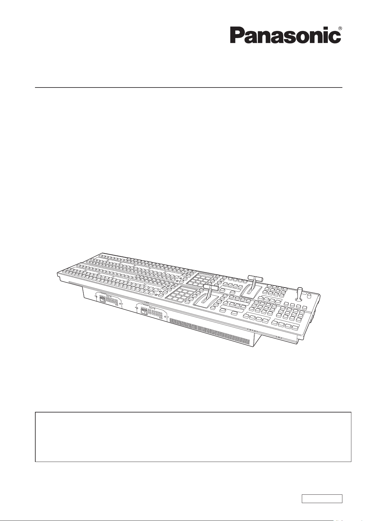
Operating Instructions
Control Panel
Model No. AV-HS60C1P
Model No. AV-HS60C2P
Model No. AV-HS60C1E
Model No. AV-HS60C2E
This manual is an excerpted version of the Operating Guide. For more information, please visit the Panasonic
website (http://pro-av.panasonic.net/en/manual/index.html), and refer to the Operating Guide (PDF).
This manual is common to all the models.
fAV-HS60C1P/AV-HS60C2P: Single Power Supply model
fAV-HS60C1E/AV-HS60C2E: Redundant Power Supply model
Before operating this product, please read the instructions carefully and save this manual for future use.
FJ0214NN0 -YI
Printed in Japan
ENGLISH
VQT5J58
Page 2
Read this rst! (For AV-HS60C1P/AV-HS60C2P)
Read this rst!
(For AV-HS60C1P/AV-HS60C2P)
WARNING:
Installation should only be performed by qualified
installation personnel.
Improper installation may result in the entire
apparatus falling down and causing injury.
CAUTION
RISK OF ELECTRIC SHOCK
DO NOT OPEN
CAUTION: TO REDUCE THE RISK OF ELECTRIC SHOCK,
REFER TO SERVICING TO QUALIFIED SERVICE PERSONNEL.
DO NOT REMOVE COVER (OR BACK).
NO USER SERVICEABLE PARTS INSIDE.
The lightning flash with arrowhead symbol,
within an equilateral triangle, is intended to
alert the user to the presence of uninsulated
“dangerous voltage” within the product’s
enclosure that may be of sufficient magnitude
to constitute a risk of electric shock to
persons.
The exclamation point within an equilateral
triangle is intended to alert the user to
the presence of important operating and
maintenance (servicing) instructions in the
literature accompanying the appliance.
WARNING:
This equipment must be grounded.
To ensure safe operation, the three-pin plug must
be inserted only into a standard three-pin power
outlet which is effectively grounded through
normal household wiring.
Extension cords used with the equipment must
have three cores and be correctly wired to provide
connection to the ground. Wrongly wired extension
cords are a major cause of fatalities.
The fact that the equipment operates satisfactorily
does not imply that the power outlet is grounded
or that the installation is completely safe. For your
safety, if you are in any doubt about the effective
grounding of the power outlet, please consult a
qualified electrician.
WARNING:
• To reduce the risk of fire or electric shock, do not
expose this equipment to rain or moisture.
• To reduce the risk of fire or electric shock, keep
this equipment away from all liquids. Use and
store only in locations which are not exposed
to the risk of dripping or splashing liquids, and
do not place any liquid containers on top of the
equipment.
indicates safety information.
WARNING:
Always keep switch blank caps (large)/(small) and
memory cards (optional accessories) out of the
reach of babies and small children.
WARNING:
Fuse replacement should only be performed by
qualified personnel.
For continued protection against risk of fire,
replace only with the same type; 3.15 AH - 250 V
fuse for F1/F2.
CAUTION:
To reduce the risk of fire or electric shock and
annoying interference, use the recommended
accessories only.
CAUTION:
In order to maintain adequate ventilation, do
not install or place this unit in a bookcase, builtin cabinet or any other confined space. To
prevent risk of electric shock or fire hazard due to
overheating, ensure that curtains and any other
materials do not obstruct the ventilation.
CAUTION:
The mains plug of the power supply cord shall
remain readily operable.
The AC receptacle (mains socket outlet) shall
be installed near the equipment and shall be
easily accessible. To completely disconnect this
equipment from the AC mains, disconnect the
power cord plug from the AC receptacle.
CAUTION:
This apparatus can be operated at a voltage in the
range of 100 – 240 V AC.
Voltages other than 120 V are not intended for
U.S.A. and Canada.
Operation at a voltage other than 120 V AC may
require the use of a different AC plug. Please
contact either a local or foreign Panasonic
authorized service center for assistance in
selecting an alternate AC plug.
2
Page 3
Read this rst! (For AV-HS60C1P/AV-HS60C2P)
indicates safety information.
FCC NOTICE (USA)
This device complies with part 15 of the FCC Rules.
Operation is subject to the following two conditions:
(1) This device may not cause harmful interference, and (2) this device must accept any interference
received, including interference that may cause undesired operation.
FCC Note:
This equipment has been tested and found to comply with the limits for a class A digital device, pursuant
to Part 15 of the FCC Rules. These limits are designed to provide reasonable protection against harmful
interference when the equipment is operated in a commercial environment. This equipment generates,
uses, and can radiate radio frequency energy, and if not installed and used in accordance with the
instruction manual, may cause harmful interference to radio communications. Operation of this equipment
in a residential area is likely to cause harmful interference in which case the user will be required to correct
the interference at his own expense.
Warning:
To assure continued FCC emission limit compliance, the user must use only shielded interface cables
when connecting to external units. If DVI-D port is to be used it must be connected to PC by compatible
interface cable with two ferrite cores. Also, any unauthorized changes or modifications to this equipment
could void the user’s authority to operate it.
NOTIFICATION (Canada)
CAN ICES-3 (A)/NMB-3(A)
IMPORTANT SAFETY INSTRUCTIONS
1) Read these instructions.
2) Keep these instructions.
3) Heed all warnings.
4) Follow all instructions.
5) Do not use this apparatus near water.
6) Clean only with dry cloth.
7) Do not block any ventilation openings. Install in accordance with the manufacturer’s instructions.
8) Do not install near any heat sources such as radiators, heat registers, stoves, or other apparatus (including amplifiers) that
produce heat.
9) Do not defeat the safety purpose of the polarized or grounding-type plug. A polarized plug has two blades with one wider
than the other. A grounding-type plug has two blades and a third grounding prong. The wide blade or the third prong are
provided for your safety. If the provided plug does not fit into your outlet, consult an electrician for replacement of the
obsolete outlet.
10) Protect the power cord form being walked on or pinched particularly at plugs, convenience receptacles, and the point
where they exit from the apparatus.
11) Only use attachments/accessories specified by the manufacturer.
12) Use only with the cart, stand, tripod, bracket, or table specified by the manufacturer, or sold with the apparatus.
When a cart is used, use caution when moving the cart/apparatus combination to avoid injury from tip-over.
13) Unplug this apparatus during lightning storms or when unused for long periods of time.
14) Refer all servicing to qualified service personnel. Servicing is required when the apparatus has been damaged
in any way, such as power-supply cord or plug is damaged, liquid has been spilled or objects have fallen into the
apparatus, the apparatus has been exposed to rain or moisture, does not operate normally, or has been dropped.
3
Page 4

Read this rst! (For AV-HS60C1E/AV-HS60C2E)
Read this rst!
(For AV-HS60C1E/AV-HS60C2E)
WARNING:
Installation should only be performed by qualified
installation personnel.
Improper installation may result in the entire
apparatus falling down and causing injury.
WARNING:
This equipment must be earthed.
To ensure safe operation, the three-pin plug must
be inserted only into a standard three-pin power
point which is effectively earthed through the
normal household wiring.
Extension cords used with the equipment must
have three cores and be correctly wired to provide
connection to the earth. Wrongly wired extension
cords are a major cause of fatalities.
The fact that the equipment operates satisfactorily
does not imply that the power point is earthed or
that the installation is completely safe. For your
safety, if you are in any doubt about the effective
earthing of the power point, please consult a
qualified electrician.
WARNING:
• To reduce the risk of fire or electric shock, do
not expose this equipment to rain or moisture.
• To reduce the risk of fire or electric shock, keep
this equipment away from all liquids. Use and
store only in locations which are not exposed
to the risk of dripping or splashing liquids, and
do not place any liquid containers on top of the
equipment.
WARNING:
Always keep switch blank caps (large)/(small) and
memory cards (optional accessories) out of the
reach of babies and small children.
indicates safety information.
WARNING:
Fuse replacement should only be performed by
qualified personnel.
For continued protection against risk of fire,
replace only with the same type; 3.15 AH - 250 V
fuse for F1/F2.
CAUTION:
Do not remove panel covers by unscrewing.
To reduce the risk of electric shock, do not remove
the covers. No user serviceable parts inside.
Refer servicing to qualified service personnel.
CAUTION:
To reduce the risk of fire or electric shock and
annoying interference, use the recommended
accessories only.
CAUTION:
In order to maintain adequate ventilation, do
not install or place this unit in a bookcase, builtin cabinet or any other confined space. To
prevent risk of electric shock or fire hazard due to
overheating, ensure that curtains and any other
materials do not obstruct the ventilation.
CAUTION:
The mains plug of the power supply cord shall
remain readily operable.
The AC receptacle (mains socket outlet) shall
be installed near the equipment and shall be
easily accessible. To completely disconnect this
equipment from the AC mains, disconnect the
power cord plug from the AC receptacle.
EEE Yönetmeliğine Uygundur.
EEE Complies with Directive of Turkey.
4
Page 5

Read this rst! (For AV-HS60C1E/AV-HS60C2E)
EMC NOTICE FOR THE PURCHASER/USER OF THE APPARATUS
1. Applicable standards and operating environment
The apparatus is compliant with:
• standards EN55103-1 and EN55103-2, and
• electromagnetic environments E4.
In a residential, commercial, light industrial and urban outdoors environment, this product may cause radio
interference.
2. Pre-requisite conditions to achieving compliance with the above standards
<1> Peripheral equipment to be connected to the apparatus and special connecting cables
• The purchaser/user is urged to use only equipment which has been recommended by us as peripheral equipment
to be connected to the apparatus.
• The purchaser/user is urged to use only the connecting cables described below.
<2> For the connecting cables, use shielded cables which suit the intended purpose of the apparatus.
• Video signal connecting cables
Use double shielded coaxial cables, which are designed for 75-ohm type high-frequency applications, for SDI
(Serial Digital Interface).
Coaxial cables, which are designed for 75-ohm type high-frequency applications, are recommended for analog
video signals.
• Audio signal connecting cables
If your apparatus supports AES/EBU serial digital audio signals, use cables designed for AES/EBU.
Use shielded cables, which provide quality performance for high-frequency transmission applications, for analog
audio signals.
• Other connecting cables (IEEE1394, USB)
Use double shielded cables, which provide quality performance for high-frequency applications, as connecting
cables.
• When connecting to the DVI signal terminal, use a cable with a ferrite core.
• If your apparatus is supplied with ferrite core(s), they must be attached on cable(s) following instructions in this
manual.
3. Performance level
The performance level of the apparatus is equivalent to or better than the performance level required by these
standards.
However, the apparatus may be adversely affected by interference if it is being used in an EMC environment, such as an
area where strong electromagnetic fields are generated (by the presence of signal transmission towers, cellular phones,
etc.). In order to minimize the adverse effects of the interference on the apparatus in cases like this, it is recommended
that the following steps be taken with the apparatus being affected and with its operating environment:
1. Place the apparatus at a distance from the source of the interference.
2. Change the direction of the apparatus.
3. Change the connection method used for the apparatus.
4. Connect the apparatus to another power outlet where the power is not shared by any other appliances.
5
Page 6

Read this rst! (For AV-HS60C1E/AV-HS60C2E)
indicates safety information.
Caution for AC Mains Lead
FOR YOUR SAFETY PLEASE READ THE FOLLOWING TEXT CAREFULLY.
This product is equipped with 2 types of AC mains cable. One is for continental Europe, etc. and the other one
is only for U.K.
Appropriate mains cable must be used in each local area, since the other type of mains cable is not suitable.
FOR CONTINENTAL EUROPE, ETC.
Not to be used in the U.K.
FOR U.K. ONLY
This appliance is supplied with a moulded three pin mains
plug for your safety and convenience.
A 13 amp fuse is fitted in this plug.
Should the fuse need to be replaced please ensure that
the replacement fuse has a rating of 13 amps and that it
is approved by ASTA or BSI to BS1362.
Check for the ASTA mark
body of the fuse.
If the plug contains a removable fuse cover you must
ensure that it is refitted when the fuse is replaced.
If you lose the fuse cover the plug must not be used
until a replacement cover is obtained.
A replacement fuse cover can be purchased from your
local Panasonic Dealer.
or the BSI mark on the
FOR U.K. ONLY
If the plug supplied is not suitable for your socket outlet,
it should be cut off and appropriate one fitted.
How to replace the fuse
1. Open the fuse compartment with a screwdriver.
2. Replace the fuse.
Fuse
Manufactured by: Panasonic Corporation, Osaka, Japan
Importer’s name and address of pursuant to EU rules:
Panasonic Testing Centre
Panasonic Marketing Europe GmbH
Winsbergring 15, 22525 Hamburg, Germany
6
Page 7

Read this rst! (For AV-HS60C1E/AV-HS60C2E)
Declaration of Conformity
with the requirements of Technical Regulation on the Restriction Of the use of certain Hazardous
Substances in Electrical and Electronic Equipment
(adopted by Order №1057 of Cabinet of Ministers of Ukraine)
The Product is in conformity with the requirements of Technical Regulation on the Restriction Of the use of certain Hazardous
Substances in electrical and electronic equipment (TR on RoHS).
The content of hazardous substance with the exemption of the applications listed in the Annex №2 of TR on RoHS:
1. Lead (Pb) – not over 0,1 % or 1000wt ppm;
2. Cadmium (Cd) – not over 0,01 % or 100wt ppm;
3. Mercury (Hg) – not over 0,1 % or 1000wt ppm;
4. Hexavalent chromium (Cr6+) – not over 0,1 % or 1000wt ppm;
5. Polybrominated biphenyls (PBBs) – not over 0,1 % or 1000wt ppm;
6. Polybrominated diphenyl ethers (PBDEs) – not over 0,1 % or 1000wt ppm.
Декларация о Соответствии
Требованиям Технического Регламента об Ограничении Использования некоторых Вредных
Веществ в электрическом и электронном оборудовании
(утверждённого Постановлением №1057 Кабинета Министров Украины)
Изделие соответствует требованиям Технического Регламента об Ограничении Использования некоторых Вредных
Веществ в электрическом и электронном оборудовании (ТР ОИВВ).
Содержание вредных веществ в случаях, не предусмотренных Дополнением №2 ТР ОИВВ:
1. свинец (Pb) – не превышает 0,1 % веса вещества или в концентрации до 1000 миллионных частей;
2. кадмий (Cd) – не превышает 0,01 % веса вещества или в концентрации до 100 миллионных частей;
3. ртуть (Hg) – не превышает 0,1 % веса вещества или в концентрации до 1000 миллионных частей;
4. шестивалентный хром (Cr6+)– не превышает 0,1 % веса вещества или в концентрации до 1000 миллионных
частей;
5. полибромбифенолы (PBB) – не превышает 0,1 % веса вещества или в концентрации до 1000 миллионных частей;
6. полибромдифеноловые эфиры (PBDE) – не превышает 0,1 % веса вещества или в концентрации до 1000
миллионных частей.
Декларація про Відповідність
Вимогам Технічного Регламенту Обмеження Використання деяких Небезпечних Речовин в
електричному та електронному обладнанні
(затвердженого Постановою №1057 Кабінету Міністрів України)
Виріб відповідає вимогам Технічного Регламенту Обмеження Використання деяких Небезпечних Речовин в
електричному та електронному обладнанні (ТР ОВНР).
Вміст небезпечних речовин у випадках, не обумовлених в Додатку №2 ТР ОВНР, :
1. свинець(Pb) – не перевищує 0,1 % ваги речовини або в концентрації до 1000 частин на мільйон;
2. кадмій (Cd)– не перевищує 0,01 % ваги речовини або в концентрації до 100 частин на мільйон;
3. ртуть(Hg) – не перевищує 0,1 % ваги речовини або в концентрації до 1000 частин на мільйон;
4. шестивалентний хром (Cr6+ ) – не перевищує 0,1 % ваги речовини або в концентрації до 1000 частин на мільйон;
5. полібромбіфеноли (PBB) – не перевищує 0,1% ваги речовини або в концентрації до 1000 частин на мільйон;
6. полібромдефенілові ефіри (PBDE) – не перевищує 0,1 % ваги речовини або в концентрації до 1000 частин на
мільйон.
7
Page 8

Contents
Contents
Read this rst! (For AV-HS60C1P/AV-HS60C2P) 2
Read this rst! (For AV-HS60C1E/AV-HS60C2E) 4
Overview 9
Overview 9
Ratings display 9
Installation 9
Accessories 9
Part Names and Functions 1 0
Operation panel 1 0
Front panel 1 4
Rear panel 15
Specications 1 6
How to read this document
r Abbreviations
The following abbreviations are used in this document.
f The model numbers of the Main Frames AV-HS60U1P/AV-HS60U2P, AV-HS60U1E/AV-HS60U2E are described as “AV-HS60U1”/“AV-HS60U2”.
f The model numbers of the Control Panels AV-HS60C1P/AV-HS60C2P, AV-HS60C1E/AV-HS60C2E are described as “AV-HS60C1”/“AV-HS60C2”.
f The model number of the Menu Panel AV-HS60C3G is described as “AV-HS60C3”.
8
Page 9

Overview
Overview
Overview
AV-HS60C1/AV-HS60C2 is the Control Panel AV-HS60C1/AV-HS60C2 with 2ME and 24 crosspoint buttons, which congures the switcher system of
AV-HS6000.
AV-HS60C1 is the single power supply model, and AV-HS60C2 is the redundant power supply model.
For detailed operations, refer to the Operating Guide of the AV-HS6000 series.
Ratings display
The name, model number, and electrical ratings of the unit are indicated on its rear panel.
Installation
Refer to the Operating Guide of the AV-HS6000 series.
Accessories
f AC cable
- AV-HS60C1P: 1 cable, AV-HS60C2P: 2 cables
- AV-HS60C1E: 2 cables, AV-HS60C2E: 4 cables
f LAN cable: 1 cable (used to connect with the Main Frame AV-HS60U1/AV-HS60U2)
f Switch blank cap (large): 24 caps
f Switch blank cap (small): 12 caps
NOTE
@@
t After removing the product from its container, dispose of the AC cable cap and packing materials in an appropriate manner.
9
Page 10

Part Names and Functions
Part Names and Functions
Operation panel
1 2 3 4 5
4
2
1
3
CAMERA
CAMERA
CAMERA
CAMERA
3
2
1
4
4
2
1
3
CAMERA
CAMERA
CAMERA
CAMERA
4
1
3
2
8
7
6
5
CAMERA
CAMERA
CAMERA
CAMERA
6
8
5
7
8
7
6
5
CAMERA
CAMERA
CAMERA
CAMERA
5
8
7
6
1 Crosspoint area
2 Multi-selection panel area
3 Transition area
4 KEY/DSK operation area
5 Positioner area
10
9
CAMERA
CAMERA
10
9
10
9
CAMERA
CAMERA
9
10
15
CG1V14VTR413VTR312VTR211VTR1
15
CG1V14VTR413VTR312VTR211VTR1
SHOT MEMORY
XPT
CB AUX
ME1 ME1 ME1
ME1
ME1
BUS
SHFT
23
21
20
17
STILL1V16CG2V
CLIP1V19CLIP1V18STILL2V
20
17
STILL1V16CG2V
CLIP1V19CLIP1V18STILL2V
24
22
BAR
CB1
ME1
CB2
RECALL
STORE
DEL
CLIP1
REGISTER
BUS
SHFT
23
21
24
22
BAR
CB1
ME1
CB2
RECALL
STORE
DEL
CHR
MIX
0s15f
MIX
2s00f
LIN PinP PinP
WIPE
WIPE
1s00f
1s00f
ME1
WIPE
1s00f
CG5V CG6V CAM1 CAM2
LIN
PinP PinP
LIN
WIPE
WIPE
WIPE
WIPE
1s15f
1s15f
2s00f
2s00f
MIX
ME2
2s00f
CG5V CG6V CAM1 CAM2
CG1V CG2V CG3V CG4V
Crosspoint area
2
3
3
2
1
1
3
CAMERA
CAMERA
CAMERA
CAMERA
6
5
CAMERA
CAMERA
CAMERA
4
5
6
9
8
7
CAMERA
CAMERA
9
8
7
CAMERA
12
10
VTR211VTR1
10
4
2
4
4
3
2
CAMERA
1
CAMERA
CAMERA
CAMERA
1
3
2
6
5
CAMERA
CAMERA
CAMERA
4
5
6
9
8
7
CAMERA
CAMERA
9
8
7
1 KEY bus selector buttons (KEY BUS DELEGATION)
Switches functions that can be operated using the KEY bus crosspoint buttons.
<AUX 1/2> to <AUX 15/16>
buttons
<KEY1 F/S> to <KEY4 F/S>
buttons
<VMEM F/S> button
Switches to the source selector buttons for the AUX buses.
f The <AUX 1/2> to <AUX 3/4> buttons have the MIX transition function.
f The <AUX 1/2> to <AUX 15/16> buttons have the crosspoint link coupling function.
Switches to the source selector buttons for the key ll buses or key source buses.
f Can be congured so that the key ll and key source are linked. The link setting can be made from the <CONF> button
on the top menu → [SOURCE LINK] → [Key Assign] tab → [Master/Slave].
Switches the source selector buttons for the ll buses or source buses of [CLIP1] through [CLIP4] (video memory) and
[STILL1] through [STILL4] (still image memory) input buses.
<DISP> button* Switches to the source selector buttons for the DISP buses to be displayed on the Menu Panel AV-HS60C3.
<UTIL 1/2> button*
<MCRO> button*
<DSK1 F/S> to <DSK4 F/S>
buttons
Switches to the source selector buttons for the utility 1 bus/utility 2 bus that can be inserted to background wipe borders
and backgrounds, and key edges.
Switches to the start button to play back the macro memory assigned to the KEY bus crosspoint buttons. The
assignment can be made from the <MEM> button on the top menu → [MACRO] → [XPT Assign] tab.
Switches to the source selector buttons for the DSK ll buses or DSK source buses.
f Can be congured so that the key ll and key source are linked. The link setting can be made from the <CONF> button
on the top menu → [SOURCE LINK] → [Key Assign] tab → [Master/Slave].
* This function will be available in V2.00.00 or higher.
2 KEY bus crosspoint buttons (1 to 24)
Selects the source of the bus which was selected by the KEY bus selector buttons.
Use the <2nd PAGE>/<3rd PAGE> button to select 1 to 96. (page 11)
CAMERA
12
10
VTR211VTR1
10
1
BUS
SHFT
17
16
15
STILL1V
CG2V
CG1V14VTR413VTR3
20
CB1
CLIP1V19CLIP1V18STILL2V
24
22
BAR
ME1
CB2
23
21
5
6
7
1
BUS
SHFT
24
23
22
21
17
16
15
CG2V
STILL1V
CG1V14VTR413VTR3
20
CB1
BAR
ME1
CB2
CLIP1V19CLIP1V18STILL2V
8
10
Page 11

Part Names and Functions
3 Source name display panels
(This function will be available in V2.00.00 or higher.)
Displays applications of the crosspoint buttons. The display settings of the source name display panels can be made from the <CONF> button on the
top menu → [SOURCE NAME] → [Panel Name] tab.
When operating other than macro bus: “crosspoint number” on the upper line, “input source name” on the lower line
When operating macro bus: “macro name” on the upper line, “input source name” on the lower line
4 PGM/A bus crosspoint buttons (1 to 24), PST/B bus crosspoint buttons (1 to 24)
Selects the video signals of the PGM/A bus and PST/B bus.
Use the <2nd PAGE>/<3rd PAGE> button to select 1 to 96. (page 11)
f Bus mode can be selected from the <CONF> button on the top menu → [OPERATE] → [Transition] tab → [Bus Mode] column → [Bus Mode].
5 <BUS SHFT> button
Press the <AUX 1/2> to <AUX 15/16>/<KEY1 F/S> to <KEY4 F/S>/<VMEM F/S>/<UTIL 1/2>/<DSK1 F/S> to <DSK4 F/S> buttons while holding
down the <BUS SHFT> button to switch the bus selection applications.
Example) <AUX 1/2> button
When only the <AUX 1/2> button is pressed, the KEY bus crosspoint buttons are switched to the source selector buttons of the AUX1 bus. When
the <AUX 1/2> button is pressed while the <BUS SHFT> button is held down, the KEY bus crosspoint buttons are switched to the source selector
buttons of the AUX2 bus.
6 <2nd PAGE>/<3rd PAGE> buttons
Enables the KEY bus crosspoint buttons, PGM/A bus crosspoint buttons, and PST/B bus crosspoint buttons to be used from 1 through 96.
f The pages of the buses included in the corresponding ME can be switched at once. To switch pages at individual buses, assign the <2nd
PAGE>/<3rd PAGE> button to the KEY bus crosspoint buttons, PGM/A bus crosspoint buttons, and the PST/B bus crosspoint buttons.
Button status
<2nd PAGE> button <3rd PAGE> button
Displayed page
Off Off First page (1-24)
Lit Off Second page (25-48)
Off Lit Third page (49-72)
Lit Lit Fourth page (73-96)
7 <IMAG> button
(This function will be available in V2.00.00 or higher.)
Enables/disables image effects (paint, mono colors, mosaics, defocusing, etc.) to be added to images selected at the PGM/A bus and PST/B bus.
f The setting to enable/disable image effects to be added to images selected at the KEY bus can be made from the <ME1>/<ME2> button on the top
menu → [IMAGE] → [Key1]/[Key2]/[BKGD] tab → [Paint]/[Mono]/[Mozaic/Defocus] column.
8 Bus tally
Indicates the output status of the buses. The buses that comprise the on-air tallies will light up.
Multi-selection panel area
1
CLIP1
REGISTER
2
RECALL
STORE
DEL
1 Mode selection button
Switches functions that can be operated on the multi-selection panel.
<BKGD WIPE> button*
<SHOT MEM> button Registers/recalls/deletes register memories of the shot memory.
<EVNT MEM> button*
<VMEM> button
<PLUG IN> button*
*1 Operations are limited in the version below V2.00.00.
*2 This function will be available in V2.00.00 or higher.
2 Multi-selection menu panel
When the mode selection button is pressed, the menu to be displayed is switched.
For details, refer to “Basic operations for the multi-selection panel area” in Operating Guide (PDF).
1
Selects background wipe preset.
Recalls register memories of the event memory. This button is also used to select register memories during EMEM-LINK
2
transition.
f Registration/editing are performed using the menu.
Records [CLIP1] through [CLIP4] (video memory) and [STILL1] through [STILL4] (still image memory) to the current
frame memories and plays them back.
f When using the Storage Module AV-HS60D1 (optional), register memories can be registered/recalled/deleted on SSD
installed in the Main Frame AV-HS60U1/AV-HS60U2.
2
Used as a plug-in software menu.
11
Page 12

Part Names and Functions
Transition area
1
7
2
3
4
5
1
6
CHR
MIX
0s15f
MIX
2s00f
LIN PinP PinP
WIPE
WIPE
1s00f
1s00f
ME1
WIPE
1s00f
8
3
9
10
1 Transition target selection buttons (<BKGD>/<KEY1>/<KEY2>/<KEY3>/<KEY4>)
Sets the operation target for the next transition to be executed when the fader lever or <AUTO>/<CUT> button is operated.
2 <MCRO ATCH> button
(This function will be available in V2.00.00 or higher.)
Switches between enabling/disabling macro attach functions assigned to the button of the corresponding ME.
f When set to on, the macro attach function is enabled.
f When pressed and held, the button to which the macro attach function is applied will blink.
3 Status display
Displays the key type (KEY only)/transition type/transition time.
4 <PATT LIMIT> button
Restricts the amount of the background wipe transition for the corresponding ME.
f When set to on, the pattern limit function is enabled.
f Set pattern limit details from the <ME1>/<ME2> button on the top menu → [BKGD] → [Position] tab → [Pattern Limit] column.
5 Transition type selection buttons (<NAM>/<MIX>/<WIPE>/<EMEM LINK>)
Switches images while overlapping. During the transition, the output total of the A bus and B bus is kept at 100%.
<MIX> button
<WIPE> button
<EMEM LINK> button Performs transition according to the patterns registered in the event memory.
In background transition, the above operation is applied when the <NAM> button is off. If the <NAM> button is on,
images are switched between the A bus and the B bus with non-additive mixing. High luminance images with the A bus
100% and the B bus 100% are output when the fader lever is positioned midway.
Performs transition according to the patterns set in the menu or selected at the wipe preset on the multi-selection panel
area.
6 <ME CHG> button
(This function will be available in V2.00.00 or higher.)
Switches ME of the operation target.
When pressed and held, switchable ME is displayed on the ME status display area. When the <MIX> button is pressed while the <ME CHG> is held
down, the operation target will be switched.
7 Wipe direction selection buttons
Selects the wipe direction when executing the background transition. The operation is not performed when the transition is a key.
<N> button Wiping proceeds in the normal direction.
<R> button Wiping proceeds in the reverse direction.
<N/R> button
The normal direction is replaced with the reverse direction (or vice versa) when the transition is completed.
f On/off of the <N>/<R> button is also switched according to the wipe direction.
8 Fader lever/transition status
Used to execute background or key transitions. When the lever is moved as far as it will go, the transition is completed. If the fader lever has been
operated during auto transition, auto transition will be switched to manual operation as soon as the fader lever position overtakes the amount of the
transition being executed.
For details on the transition status display, refer to “Transition status display” (page 13).
9 ME status area
Displays the ME of the operations target. Use the <ME CHG> button to switch the ME of the operation target.
10 transition execution button
<AUTO> button
<CUT> button Executes transition instantly.
Automatically executes transition. (Auto transition)
f To set the transition time, select the <ME1>/<ME2> button on the top menu → [BKGD] → [Transition] tab →
[Transition] column → [Time].
12
Page 13

Part Names and Functions
r Transition status display
Fig. 1 Fig. 2 Fig. 3 Fig. 4
The transition status display at the left side of the fader lever indicates not the lever position but the amount of transition, and also works during auto
transition.
During pattern limitation, the amount of limitation will also be displayed. (Fig. 1)
If the fader lever position and the amount of images do not match after memory playback or auto transition execution, every other display will be
displayed. When displayed at one side (Fig. 2, Fig. 3), push the lever towards the displayed side to make the lever position recognize.
If multiple operations of BKGD and KEY1 to KEY4 are performed in the next transition, both sides may become unmatched. In such a case, the display
will be like Fig. 4, so move the fader lever back and forth to make the lever position recognize.
KEY/DSK operation areas
1
2
3
4
CG5V CG6V CAM1 CAM2
CG1V CG2V CG3V CG4V
5
KEY operation area DSK operation area
1 Operation target selection buttons (<KEY1>/<KEY2>/<KEY3>/<KEY4>/<DSK1>/<DSK2>/<DSK3>/<DSK4>)
Selects the operation target for key/DSK preset memory.
Switches target to be displayed in the SEL KEYPVW output.
2 Key/DSK preset memory buttons (<1>/<2>/<3>/<4>)
(This function will be available in V2.00.00 or higher.)
Recalls/registers the key preset memory.
f Short press: Recalls data saved to the corresponding button. (Recall)
f Long press: Stores the current key settings to the corresponding button. (Store)
3 <KEY1 ON>/<KEY2 ON>/<KEY3 ON>/<KEY4 ON>/<DSK1 ON>/<DSK2 ON>/<DSK3 ON>/<DSK4 ON> buttons
Executes/cancels each key with a cut transition.
4 Source name display panels
Displays the source name selected for each key.
5 <KEY1 TRNS>/<KEY2 TRNS>/<KEY3 TRNS>/<KEY4 TRNS>/<DSK1 TRNS>/<DSK2 TRNS>/<DSK3 TRNS>/<DSK4 TRNS> buttons
Executes transition with the transition type and transition time for each key set in the menu.
1
2
3
4
5
Positioner area
1
2
4
5
6
3
1 Memory card access LED
Lights up while accessing the memory card.
Do not turn off the power of the unit or eject the memory card while lit. The memory card or data in the memory card may be damaged.
2 Memory card slot
Insert an SD memory card (optional) or an SDHC memory card (optional).
3 Positioner buttons (<X>/<Y>)
<X> button Enables the X-axis operation of the positioner (horizontal direction).
<Y> button Enables the Y-axis operation of the positioner (vertical direction).
7
13
Page 14

Part Names and Functions
4 Z-axis dial
Used to set the numeric values at the numeric entry items on the Menu Panel AV-HS60C3.
It corresponds to the third from the left of the rotary encoders on the Menu Panel AV-HS60C3.
5 Positioner
Used to set the numeric values at the numeric entry items on the Menu Panel AV-HS60C3.
f X axis (horizontal direction): Corresponds to the leftmost of the rotary encoders on the Menu Panel AV-HS60C3.
f Y axis (vertical direction): Corresponds to the second from the left of the rotary encoders on the Menu Panel AV-HS60C3.
6 <FINE> button
Changes the amount of change in parameter for the positioner operation.
When set to on, ner adjustments can be made.
7 <ENBL> button
Lit: Enables operations of the positioner and Z-axis dial.
Off: Disables operations of the positioner and Z-axis dial.
NOTE
@@
t This unit detects the position of the positioner and sets the position to the center by the time when the startup is completed after power is turned on.
Do not touch the positioner until the startup of the unit is completed.
r Memory cards
Memory cards used with the unit should conform to SD or SDHC standards.
Be sure to format memory cards using the unit.
Memory cards with the following capacity can be used for the unit. The unit does not support SDXC memory cards.
SD memory card: 8 MB to 2 GB
SDHC memory card: 4 GB to 32 GB
For the latest information not available in the Operating Guide, visit the following website.
http://pro-av.panasonic.net/ (English only)
f Keep the following points in mind when using or storing memory cards.
- Avoid high temperatures/humidities.
- Do not expose to water droplets.
- Avoid electrical charges.
Front panel
Power supply 1
Power supply 2
2 3 2 31 1
1 <POWER> switch (with safety guard)
Turns power on/off.
f The single power supply model (AV-HS60C1) does not have the <POWER> switch for the power supply 2.
f When turning off the power of the redundant power supply model (AV-HS60C2), set both <POWER> switches for the power supply 1 and the
power supply 2 to <OFF>.
2 Power indicator
When power is input into the <AC IN 1>/<AC IN 2> terminal, both <POWER> switches of the power supply 1 and the power supply 2 will light up
when they are set to <ON>.
f AV-HS60C1 does not have the power indicator for the power supply 2.
3 Alarm indicator <ALARM>
Lights up when the cooling fan of the Control Panel AV-HS60C1/AV-HS60C2 has stopped or when there are problems (voltage declines) with the
power supply. In such cases, an alarm message is displayed on the Menu Panel AV-HS60C3. For the redundant power supply model (AV-HS60C2),
an alarm will be displayed if both <POWER> switches of the power supply 1 and the power supply 2 have not turned on.
When an alarm has occurred, details of the problem can be checked from the <SYS> button on the top menu → [MAINTENANCE] → [Alarm] tab.
The alarm status can be output from the <GPI I/O> terminal of the Control Panel AV-HS60C1/AV-HS60C2 to external devices.
f AV-HS60C1 does not have the alarm indicator for the power supply 2.
NOTE
@@
t When an alarm has occurred, stop using the unit immediately, and be sure to contact your dealer. Continuous use of the unit even after an alarm has
occurred could damage the unit.
14
Page 15

Part Names and Functions
Rear panel
1
MAIN FRAME GPI I/O COM1 (M) COM2 (RS-232)
MENU PANEL
2 3 54 6 7 8 9
1 <AC IN 1>/<AC IN 2> terminals (signal: AC)
Connects one end of the supplied AC cable to this terminal and the other end to the AC outlet. (AC 100 V to 240 V, 50 Hz/60 Hz)
f The supplied AC cable has a 3-pin plug with a grounding terminal. Connect to a 3-pin power outlet which is equipped with a grounding terminal.
f If a 3-point power outlet is not available, be sure to consult your dealer.
2 <MAIN FRAME> terminal (connector: RJ-45/signal: 100Base-TX)
Connects to the <PANEL> terminal or <LAN> terminal of the Main Frame AV-HS60U1/AV-HS60U2.
f When connected to the <LAN> terminal, no video will be displayed on the Menu Panel AV-HS60C3.
3 <MENU PANEL> terminal (connector: DVI-D/signal: independent signal)
Connects the Menu Panel AV-HS60C3.
f Cannot be used concurrently with a DVI monitor (computer) connected to the <DVI-D> terminal. Select with the display selector switch.
f This is the dedicated interface for the Menu Panel AV-HS60C3. Do not connect with DVI output devices.
4 Display selector switch
Switches the terminal to be used to the <MENU PANEL> terminal or <DVI-D> terminal depending on the connected device.
Switch this when the power is off. Output will not be performed properly if switched with the power turned on. Restarting of the unit will be necessary.
Set the power to <OFF>, and then set it back to <ON>.
5 <DVI-D> terminal (connector: DVI-D/signal:DVI OUT)
Connects the DVI monitor (computer) used for the menu display.
f Monitor resolution: 1366×768 compatible monitor
f Cannot be used concurrently with the <MENU PANEL> terminal. Select with the display selector switch.
6 <USB> terminal (connector: USB (type A, female)/signal: USB)
Used for the menu operation of the DVI monitor (computer).
f Cannot be used for the Menu Panel AV-HS60C3.
7 <COM1 (M)> terminal (connector: D-sub 9-pin (female), inch screw/signal: RS-422)
Used for master connection of external devices.
8 <COM2 (RS-232)> terminal (connector: D-sub 9-pin (male), inch screw/signal: RS-232)
Used to control external device.
9 <GPI I/O> terminal (connector: D-sub 25-pin (female), inch screw/signal: GPI)
Equipped with 8 contact input ports (GPI IN) that control the unit externally, 10 output ports (GPI OUT) that output tallies or status information from
the unit, and an alarm output port (ALARM OUT).
10 <F1>/<F2> terminals
(Fuse)
11 <SIGNAL GND> terminal (signal: SG)
Connects to the ground of the system.
NOTE
@@
t For the cable connecting to the <DVI-D> terminal, use a double-shielded cable.
t For the cable connecting to the <MAIN FRAME> terminal, <COM1 (M)>/<COM2 (RS-232)> terminal, and <GPI I/O> terminal, use a shielded cable.
DVI-D USB
10 11
15
Page 16

Specications
Specications
Power supply
AC 100 V to 240 V, 50 Hz/60 Hz
Power consumption
40 W
AV-HS60C2 supports redundant power supply.
indicates safety information.
Control terminal
<MAIN FRAME> terminal Compatible with 100Base-TX and AUTO-MDIX (For Control Panel AV-HS60C1/AV-HS60C2 connection)
<MENU PANEL> terminal Used only for the Menu Panel AV-HS60C3
<DVI-D> terminal Used for displaying menus to the DVI monitor (computer)
<USB> terminal For DVI monitor (computer) menu operation
Display selector switch Switch for selecting <MENU PANEL> terminal or <DVI-D> terminal
<COM1 (M)> terminal RS-422 control terminal
<COM2 (RS-232)> terminal RS-232 control terminal
<GPI I/O> terminal GPI IN: 8 inputs, general-purpose, photocoupler sensing
ME number 2ME
f Connection cable (supplied with AV-HS60C1/AV-HS60C2): LAN cable (CAT5E), straight cable, STP (Shielded Twisted
Pair), 10 m (32.8 ft)
f Connector: RJ-45
* When connected to the <LAN> terminal, no video will be displayed on the Menu Panel AV-HS60C3.
f Connector: DVI-D
f Because an independent signal format is used, cannot be displayed on a DVI-D monitor.
f Cannot be used concurrently with a DVI-D monitor (computer) connected to the <DVI-D> terminal. Select with the
display selector switch.
f Connector: DVI-D
f Monitor resolution: 1366×768 compatible monitor
f Cannot be used concurrently with the <MENU PANEL> terminal. Select with the display selector switch.
f Connector: USB (Type A, female)
f Cannot be used for the Menu Panel AV-HS60C3.
For master connection for controlling external devices
f Connector: D-sub 9-pin (female), inch screw
For master/slave connection for controlling external devices
f Connector: D-sub 9-pin (female), inch screw
f Switchable by menu
ALARM OUT: 1 output, open collector output (negative logic)
GPI OUT: 10 outputs, selected from general purpose, tally
Open collector output
f Connector: D-sub 25-pin (female), inch screw
f Logic is switchable by menu.
NOTE
@@
t Use with the same segment is recommended for the devices which are connected to the unit. If the unit is connected to the devices whose segments
are different, events dependent upon the settings inherent to the network equipment, for instance, may occur. Thoroughly check the connections with
the devices to which the unit will be connected prior to the start of operation.
Other
Ambient operating temperature
Humidity 10% to 90% (no condensation)
Dimensions (W×H×D) 980 mm×153.4 mm×267 mm (38-19/32 inches×6-1/32 inches×10-1/2 inches) (excluding protrusions)
Mass
r For AV-HS60C1E/AV-HS60C2E
Inrush current, measured according to European standard EN55103-1, on initial switch-on: 3 A, after a supply interruption of 5 s: 25 A (Each mains
input)
0°C to 40°C (32°F to 104°F)
AV-HS60C1: Approx. 13.0 k] (28.6 lbs.) (excluding accessories)
AV-HS60C2: Approx. 13.9 k] (30.6 lbs.) (excluding accessories)
16
Page 17

Memo
17
Page 18

Memo
18
Page 19

Memo
19
Page 20

Information on Disposal for Users of Waste Electrical & Electronic Equipment (private households)
This symbol on the products and/or accompanying documents means that used electrical and electronic products should
not be mixed with general household waste.
For proper treatment, recovery and recycling, please take these products to designated collection points, where they will be
accepted on a free of charge basis. Alternatively, in some countries you may be able to return your products to your local
retailer upon the purchase of an equivalent new product.
Disposing of this product correctly will help to save valuable resources and prevent any potential negative effects on human
health and the environment which could otherwise arise from inappropriate waste handling.
Please contact your local authority for further details of your nearest designated collection point.
Penalties may be applicable for incorrect disposal of this waste, in accordance with national legislation.
For business users in the European Union
If you wish to discard electrical and electronic equipment, please contact your dealer or supplier for further information.
Information on Disposal in other Countries outside the European Union
This symbol is only valid in the European Union.
If you wish to discard this product, please contact your local authorities or dealer and ask for the correct method of disposal.
Web Site: http://panasonic.net
©Panasonic Corporation 2014
 Loading...