

Panasonic AV-HS60U2P, AV-HS60U2E, AV-HS60U1P, AV-HS60U1E, AV-HS60C3G User Manual
...
Operating Guide
(Included Installation Instructions)
2ME Live Switcher
AV-HS6000 Series
Main Frame
Model No. AV-HS60U1P/AV-HS60U2P
Model No. AV-HS60U1E/AV-HS60U2E
Menu Panel
Model No. AV-HS60C3G
Control Panel
Model No. AV-HS60C1P/AV-HS60C2P
Model No. AV-HS60C1E/AV-HS60C2E
Before operating this product, please read the instructions carefully and save this manual for future use.
W0214NN0 -YI
ENGLISH
VQT5J51A(E)

Information on software for this product
Included with this product is software licensed under the GNU General Public License (GPL) and GNU Lesser General Public License (LGPL), and
users are hereby informed that they have the right to obtain, change, and redistribute the source codes of this software.
Included with this product is software which is licensed under MIT-License.
To obtain the source codes, visit the following website.
http://pro-av.panasonic.net/
The manufacturer asks users to refrain from directing inquiries concerning the source codes they have obtained and other details to its representatives.
Trademarks and registered trademarks
f Microsoft®, Windows® 7, Windows® 8, and Internet Explorer® are either registered trademarks or trademarks of Microsoft Corporation in the United
States and/or other countries.
®
f Intel
and Intel® CoreTM are trademarks or registered trademarks of Intel Corporation or its subsidiaries in the United States and/or other countries.
®
f Adobe
and Reader® are either registered trademarks or trademarks of Adobe Systems Incorporated in the United States and/or other countries.
f SDHC Logo is a trademark of SD-3C, LLC.
®
f Primatte
f The copyrights of Primatte
f The patents for Primatte
is a registered trademark of IMAGICA DIGIX Inc.
®
belong to IMAGICA DIGIX Inc.
®
belong to IMAGICA DIGIX Inc.
f Other names of companies and products contained in this document may be trademarks or registered trademarks of their respective owners.
Copyright and license
Distributing, copying, disassembling, reverse compiling, reverse engineering, and also exporting in violation of export laws of the software provided with
this unit are expressly prohibited.
How to read this document
r Abbreviations
The following abbreviations are used in this document.
f Microsoft
f Windows
f The model numbers of the Main Frames AV-HS60U1P/AV-HS60U2P, AV-HS60U1E/AV-HS60U2E are described as “AV-HS60U1”/“AV-HS60U2”.
f The model numbers of the Control Panels AV-HS60C1P/AV-HS60C2P, AV-HS60C1E/AV-HS60C2E are described as “AV-HS60C1”/“AV-HS60C2”.
f The model number of the Menu Panel AV-HS60C3G is described as “AV-HS60C3”.
f The model number of the optional Storage Module AV-HS60D1G is described as “AV-HS60D1”.
f The model number of the optional Chromakey Software AV-SFU60G is described as “AV-SFU60”.
f Both SD memory cards and SDHC memory cards are described as “memory cards”.
When individual descriptions are provided, they are featured individually.
f Personal computers are described as “computers”.
®
Windows® 7 Professional SP1 32/64-bit is abbreviated to Windows 7. Microsoft® Windows® 8 Pro 32/64-bit is abbreviated to Windows 8.
®
Internet Explorer® 8.0, Windows® Internet Explorer® 9.0, and Windows® Internet Explorer® 10.0 are abbreviated to Internet Explorer.
r Illustrations and screen displays featured in this document
f What is shown in this document’s illustrations and screen displays may differ from how it is actually appears.
r Conventions used in this document
f Words and phrases in [ ] brackets indicate descriptions displayed in the Menu Panel AV-HS60C3 or the multi-selection menu panel, source name
display panel, status display area of the Control Panel AV-HS60C1/AV-HS60C2.
f Words and phrases in < > brackets indicate design text used on this unit, such as button names.
r Reference pages
f In this document, reference pages are described as (page 00).
– 2 –

Contents
Contents
Chapter 1 Overview 5
Before use 6
Features 7
Conguration of the AV‑HS6000 series 8
Conguration list of the AV‑HS6000 series 8
Accessories of the AV-HS6000 series 8
Required computer environment 9
Precautions for use 1 0
Chapter 2 Installation and Connection (To
installation personnel) 11
Installation (To installation personnel) 12
Installing the Main Frame AV-HS60U1/AV-HS60U2 12
Installing the Control Panel AV-HS60C1/AV-HS60C2 13
Installing the Menu Panel AV-HS60C3 13
Attaching the Storage Module AV-HS60D1 (SSD) 13
Installing the Chromakey Software AV-SFU60 14
Connection (To installation personnel) 15
Connecting the imaging systems 15
Connecting the control systems 16
Chapter 3 Part Names and Functions 18
Main Frame AV‑HS60U1/AV‑HS60U2 19
Front panel 19
Rear panel 19
Control Panel AV‑HS60C1/AV‑HS60C2 21
Operation panel 21
Front panel 25
Rear panel 26
Menu Panel AV‑HS60C3 27
Operation panel 27
Rear panel 28
Chapter 4 Preparations 29
Turning power on/off 3 0
Turning power on 30
Turning power off 30
Basic menu operations 31
Menu conguration and operations 31
Numeric entry item operations 32
Text entry item operations 33
Color settings menu operations 34
Other buttons 35
Basic operations for the multi‑selection panel area 36
Background wipe preset menu 36
Shot memory menu 37
Event memory menu 38
Video memory menu 39
Plug-in menu 40
Menu delegation function 41
Enabling/disabling the menu delegation function 41
Menu delegation function list 41
Various settings 42
Network settings 42
Setting signal formats 42
Setting sync signals 42
Setting input signals 42
Button settings 43
Setting output signals 43
Setting MultiView displays 44
Setting a tally 44
Setting the state replicated when power is on 44
Setting date and time 44
Chapter 5 Basic Operations 45
Background transition 46
Selecting a bus 46
Selecting a bus using the SHIFT function 46
Selecting the bus mode 46
Transition operations 46
Wipe 48
Selecting the wipe pattern for background transition 48
Selecting the wipe direction 48
Wipe decorations (border, soft effect) 48
Modifying wipe 49
KEY 51
Selecting the key type 51
Selecting the key source 52
Key transitions 52
Key wipe transition 53
Key output 55
Adjusting the luminance key/linear key 55
Adjusting the chroma key 55
Key decorations 60
Masking the key signals 61
Flying key 61
PinP (Picture in Picture) 62
DSK (Downstream key) 65
Selecting the DSK type 65
Selecting the source type 65
Selecting the ll type 65
Selecting the DSK source 65
DSK transition 66
DSK output 66
Adjusting the luminance key/linear key 66
DSK decorations 66
Masking the DSK 68
Setting the priority 68
Setting [DSK On Link] 69
USK (Upstream key) 7 0
Selecting the USK type 70
Selecting the source type 71
Selecting the ll type
Selecting the USK source 71
Setting the USK insert 71
Adjusting the luminance key/linear key 72
Masking the USK 72
71
IMAGE 73
Setting image effects 73
Executing image effects 73
Color corrector 74
Setting the color corrector 74
Initializing the color corrector 74
Copying the setting 74
Process control 74
Tone curve 75
Adjusting the gain of color matrix 75
Internal color signals 77
Setting the color background 77
Setting the gradation 77
Switching the AUX output 78
Selecting the AUX output sources 78
Transitions of AUX1 to AUX4 buses 78
Linking AUX buses 78
Memory 79
Shot memory 79
Event memory 81
Macro memory
Key preset 90
87
Video memory 91
Recording still images (Still) 91
Recording moving images (Clip) 92
Operating the register memory 93
Using image les created on a computer 94
Playing back moving images (Clip) 95
Layout of display icons 97
Operating in the multi-selection panel area 99
Project management 100
Saving data on a memory card or storage module 100
Loading data from a memory card or the storage module 100
Editing data in a memory card or the storage module 101
Saving and loading data in/from the local computer 101
Storage 102
Memory card 102
Storage Module 104
Saving and loading data in/from the local computer 104
Chapter 6 Input/Output Signal Settings 105
Setting input signals 106
Setting the frame synchronizer 106
Setting the input mode 106
Setting the delay amount 107
– 3 –

Contents
Freezing input signals 107
Setting the source name 107
Setting the up-converter 107
Setting DVI input signals 108
Displaying video input signal information 111
Setting output signals 112
Assigning output signals 11 2
Setting the down-converter 112
Setting MultiView displays 11 4
Setting the screen layout 114
Setting the split frame and characters 114
Setting the tally display 114
Other display settings 11 5
Chapter 11 Appendix 157
Setting menu table 158
<ME1>/<ME2> button (top menu) 158
<DSK MISC> button (top menu) 161
<MEM> button (top menu) 162
<SYS> button (top menu) 163
<IN OUT> button (top menu) 165
<MV> button (top menu) 166
<PLUG IN> button (top menu) 166
<PRJ> button (top menu) 167
<CONF> button (top menu) 167
Glossary 169
Index 171
Chapter 7 CONFIG Menu 116
Disabling button operations 117
Assigning signals to buttons 118
Setting the source name 119
Setting the source name display panel 119
Setting the MultiView display 119
Setting the source link 120
Setting the key coupling 120
Linking the AUX bus 120
Setting the operation mode 121
Setting the operation mode for the crosspoint buttons 121
Setting the transition operation mode 121
Switching the ME area in the Control Panel AV-HS60C1/
AV-HS60C2
Setting the key operation mode 123
Locking the menu operation 124
122
Chapter 8 System Menu 125
System settings 126
Setting the video format function 126
Setting the output phase 126
Setting the sync signal 129
Other video signal settings 129
Network settings 130
Setting the WFM/VECT of Menu Panel AV-HS60C3 131
Setting the Main Frame AV‑HS60U1/AV‑HS60U2 132
Setting the ME output and DSK output 132
Setting the Control Panel AV‑HS60C1/AV‑HS60C2 134
Settings for the main control panel and sub control panel 134
Setting the button color 134
Setting the external connection 136
Setting a serial port 136
Setting a tally 136
Setting the GPI input/output 136
Maintenance settings 139
Software and hardware version 139
Alarm 139
Startup settings/initialization 140
Option status display and activation 141
Maintenance 141
Setting the date and time 142
Locking the menu operation 143
Chapter 9 External Interfaces 144
GPI input/output settings and alarm output 145
GPI input/output ports of the Main Frame AV-HS60U1/
AV-HS60U2 145
GPI input/output ports of the Control Panel AV-HS60C1/
AV-HS60C2 146
Serial ports 147
Serial ports of the Main Frame AV-HS60U1/AV-HS60U2 147
Serial ports of the Control Panel AV-HS60C1/AV-HS60C2 147
Plug‑in software 148
Chapter 10 Specications 149
Dimensions 150
Dimensions of the Main Frame AV-HS60U1/AV-HS60U2 150
Dimensions of the Control Panel AV-HS60C1/AV-HS60C2 151
Dimensions of the Menu Panel AV-HS60C3 152
Specications 153
Main Frame AV-HS60U1/AV-HS60U2 153
Control Panel AV-HS60C1/AV-HS60C2 155
Menu Panel AV-HS60C3 156
Storage Module 156
– 4 –

Chapter 1 Overview
Please read this chapter, and check the accessories before use.

Chapter 1 Overview — Before use
Before use
r Overview
The AV-HS6000, a new model in the HS series, employs a newly designed, easy-to-use UI graphical Control Panel AV-HS60C1/AV-HS60C2 to support
accurate switching.
And even with a 3U size compact design, it is equipped with abundant inputs and outputs for great system integration as seen by its 32 SDI and 2 DVI
inputs plus 16 SDI outputs.
To top it all off, situations where creative video production is demanded alongside fast response are handled by providing 4 DVEs per ME to enable
diverse transitions.
r Precautions
f Be sure to perform validation of the unit before use.
f Should displaying or recording of the video fail due to a malfunction of the unit or memory cards used, we will not assume liability for such failure.
r Network security
The unit also has functions which are used when it is connected to a network. Using the unit when it has been connected to a network may possibly give
rise to the following issues.
f Leakage or theft of information through this unit
f Use of this unit for illegal operations by persons with malicious intent
f Interference with or stoppage of this unit by persons with malicious intent
It is your responsibility to take precautions such as those described below to protect yourself against the above network security risks.
f Use this unit in a network secured by a rewall, etc.
f If this unit is connected to a network that includes computers, make sure that the system is not infected by computer viruses or other malicious entities
(using a regularly updated antivirus program, anti-spyware program, etc.).
The following points should be borne in mind as well.
f Use with the same segment is recommended for the devices which are connected to the unit. If the unit is connected to the devices whose segments
are different, events dependent upon the settings inherent to the network equipment, for instance, may occur. Thoroughly check the connections with
the devices to which the unit will be connected prior to the start of operation.
f Do not choose an installation location where the unit, cables and other parts will be easily damaged.
r Concerning differences in the system versions
This document describes the functions which can be actuated in any model whose system version is V2.00.00 or higher.
The applicable functions are referred to as “This function will be available in V2.00.00 or higher”.
If the model has a system version below V2.00.00, the functions concerned cannot be used.
Neither will the menus nor items concerned be displayed.
To check the system version of this unit, select the <SYS> button on the top menu → [MAINTENANCE] → [Status] tab → [System Version] in the
[System Version] column. (page 139)
For the latest information, visit the following website.
http://pro-av.panasonic.net/ (English only)
– 6 –

Chapter 1 Overview — Features
Features
r Graphical Control Panel AV‑HS60C1/AV‑HS60C2
f The multi-selection panel is set up for each ME for quick access to various functions such as wipe patterns, shot memory, and event memory.
f Tactile color LCD switch: The multi-selection panel employs switch so that you can make sure keys being pressed, supporting reliable operation.
f Crosspoint buttons: Crosspoint buttons can be grouped by buttons lights with multiple color.
f Source name display panel: The monochrome source name display panel is set up for each ME so that graphics can be displayed on the crosspoint
buttons.
r Rich array of inputs/outputs with standard 34 inputs
f The unit is equipped with SDI×32 inputs/DVI×2 inputs and SDI×16 outputs.
f All inputs have built-in frame synchronizers.
f Color correctors are installed in 8 inputs and 4 outputs. (This function will be available in V2.00.00 or higher.)
f Up-converters are installed in 4 inputs and down-converters are installed in 2 outputs.
r Diverse transitions and a full array of keyers
f The unit is equipped with 4 DVE and 2 DVE (2D) per ME to handle backgrounds and keys.
f AUX1 to AUX4 buses are equipped with MIX transitions.
f The unit is equipped with real-time high-quality chroma keying that employs Primatte
channels per ME. (This function will be available in V2.00.00 or higher.)
f The unit is equipped with 4 channels per ME (total 8 channels) of keyer which is capable of PinP.
f The unit is equipped with 4 channels of downstream keyers.
f The unit is equipped with 4 channels of upstream keyers. (This function will be available in V2.00.00 or higher.)
* Primatte® is a registered trademark of IMAGICA DIGIX Inc. The copyrights of Primatte® belong to IMAGICA DIGIX Inc. The patents for Primatte® belong to
IMAGICA DIGIX Inc.
r MultiViewer output
f The unit is equipped with 4 independent MultiViewer displays.
f Single MultiViewer can display a maximum of 16 video sources.
f Source names, tallies, audio level meters, and safety markers are displayable.
®
* algorithms. Standard 1 channel per ME is expandable up to 4
r Network function
(This function will be available in V2.00.00 or higher.)
f Web server function: The switcher can be set and operated via LAN connection.
r Redundant operation system for peace of mind
f The Main Frame AV-HS60U2 and the Control Panel AV-HS60C2 have separate power sources. (The single power supply model is also available.)
f Operation with two additional panels is possible by IP connection. (This function will be available in V2.00.00 or higher.)
r Wide range of functions to increase operability
f Shot memory, event memory, and macros memory allow you to preset and recall frequently used effects easily. (Event memory and macro memory
will be available in V2.00.00 or higher.)
f Video clips and still images can be registered up to 4ch each, allowing them to be easily used for CG wipes.
f The switcher can be set by the 10.1-inch touch-operated Menu Panel AV-HS60C3 (optional) or by a PC monitor and USB mouse.
f With plug‑in software, external device control capability can be added in accordance with the operation workow. (This function will be available in
V2.00.00 or higher.)
– 7 –

Chapter 1 Overview — Conguration of the AV‑HS6000 series
Conguration of the AV‑HS6000 series
Conguration list of the AV‑HS6000 series
Series product name AV-HS6000 series
Main Frame
Control Panel
Menu Panel AV-HS60C3
Storage Module AV-HS60D1
Chromakey Software AV-SFU60
Accessories of the AV‑HS6000 series
r Main Frame AV‑HS60U1/AV‑HS60U2
f AC cable
- AV-HS60U1P: 1 cable, AV-HS60U2P: 2 cables
- AV-HS60U1E: 2 cables, AV-HS60U2E: 4 cables
f Rack-mounted rear panel support bracket
f Screws for the rack-mounted rear panel support bracket: 8 screws
f Operating Guide of the AV-HS6000 series (Excerpted Version)
f AV-HS60U1/AV-HS60U2 Operating Instructions
Single Power Supply model AV-HS60U1
Redundant Power Supply model AV-HS60U2
Single Power Supply model AV-HS60C1
Redundant Power Supply model AV-HS60C2
r Control Panel AV‑HS60C1/AV‑HS60C2
f AC cable
- AV-HS60C1P: 1 cable, AV-HS60C2P: 2 cables
- AV-HS60C1E: 2 cables, AV-HS60C2E: 4 cables
f LAN cable: 1 cable (used to connect with the Main Frame AV-HS60U1/AV-HS60U2)
f Switch blank cap (large): 24 caps
f Switch blank cap (small): 12 caps
f AV-HS60C1/AV-HS60C2 Operating Instructions
r Menu Panel AV‑HS60C3
f Connection cable (with ferrite core) for the Control Panel AV-HS60C1/AV-HS60C2: 1 cable
f Bracket for mounting the Control Panel AV-HS60C1/AV-HS60C2
f Screws for the bracket for mounting the Control Panel AV-HS60C1/AV-HS60C2: 6 screws
f AV-HS60C3 Operating Instructions
r Storage Module (AV‑HS60D1)
f AV-HS60D1 Installation Guide
r Chromakey Software (AV‑SFU60)
(This function will be available in V2.00.00 or higher.)
f Read before use
f Software Licensing Agreement
f Pouch containing the key code
NOTE
@@
t After removing the product from its container, dispose of the AC cable cap and packing materials in an appropriate manner.
– 8 –

Chapter 1 Overview — Required computer environment
Required computer environment
NOTE
@@
t Connection with a computer connected to the <LAN> terminal of the Main Frame AV-HS60U1/AV-HS60U2 will be available in V2.00.00 or higher.
Use a host computer that satises the following conditions.
CPU Intel® CoreTM 2 DUO 2.4 GHz or more recommended
Memory 2 GB or more recommended
Network function 100Base-TX
Resolution:
Image display function
Compatible OS Microsoft
Hard disk drive 50 MB or more free memory
Other
1024×768 pixels or more
Color generation:
True Color (24 bits or more)
Windows 7:
Internet Explorer 9.0, Internet Explorer 10.0
f Internet Explorer 8.0 cannot be used.
Windows 8:
Internet Explorer 10.0
®
®
Reader
Adobe
(For viewing the Operating Guide)
– 9 –

Chapter 1 Overview — Precautions for use
Precautions for use
r Handle carefully.
Do not drop the product, or subject it to strong impact or vibration. Do not carry or move the product by the fader lever. This is important to prevent
malfunction or accidents.
r Use the product at a temperature of 0°C to 40°C (32°F to 104°F).
Avoid using the product at a cold place below 0°C (32°F) or at a hot place above 40°C (104°F), because extremely low or high temperature may
adversely affect the parts inside.
r Turn off the power before connecting or disconnecting cables.
Before connecting or disconnecting the cables, be sure to turn off the power.
r Avoid humidity and dust.
Avoid using the product at a humid, dusty place because much humidity and dust will cause damage to the parts inside.
r Maintenance
Turn off the power and wipe the product using a dry cloth. To remove stubborn dirt, dip a cloth into a diluted solution of kitchen detergent (neutral), wring
it out well, and wipe the product gently. Then, after wiping the product with a moist cloth, wipe it again with a dry cloth.
NOTE
@@
t Avoid using benzine, paint thinners and other volatile uids.
t If a chemical cleaning cloth is to be used, carefully read through the precautions for its use.
r Precaution to be observed during production
Video switching and video effect functions of this unit can be used to produce videos which icker rapidly or videos which change rapidly.
However, bear in mind when using these functions in production that the kinds of videos produced may have an adverse effect on the viewer’s physical
well-being.
r Built‑in display
Leaving the organic EL panel of the source display panel, multi-selection menu panel, and LCD panel of the Menu Panel AV-HS60C3 on with the same
image over a long period of time may result in afterimage (burn‑in). Use after conguring the screensaver settings.
The liquid crystal parts are highly precise with more than 99.99% of the pixels effective. This leaves less than 0.01% of pixels that may not light or may
remain on all the time.
These phenomena are normal and will have no effect on the images you shoot.
Condensation may form on the LCD panel if you use the unit where temperatures uctuate. Wipe it with a soft, dry cloth.
When the unit has completely cooled down, the display on the LCD monitor appears slightly darker than usual immediately after the power has been
turned on. Once the internal temperature of the unit rises, the display returns to the normal brightness.
r Touch screen
Operate with your ngers on the touch screen of the Menu Panel AV‑HS60C3. Do not touch the panel with sharp‑pointed, hard object such as a ballpoint
pen.
r When the product is to be discarded
When the product is to be discarded at the end of its service life, ask a specialized contractor to dispose of it properly in order to protect the
environment.
r Consumable parts
f Cooling fan:
This is a consumable part.
As a general rule, replace it every 5 years or so (when the unit has been operated for 15 hours a day).
f Power supply unit:
This is a consumable part.
As a general rule, replace it every 5 years or so (when the unit has been operated for 15 hours a day).
The period when the consumable parts need to be replaced will differ depending on the operating conditions.
When the time comes to replace one of these parts, be sure to ask your dealer to do the job.
– 10 –

Chapter 2 Installation and Connection (To
installation personnel)
This chapter describes installation and connection.
Chapter 2 Installation and Connection (To installation personnel) — Installation (To installation personnel)
Installation (To installation personnel)
CAUTION:
These servicing instructions are for use by qualied service personnel only. To reduce the risk of electric shock, do not perform any servicing other than that
contained in the operating instructions unless you are qualied to do so.
indicates safety information.
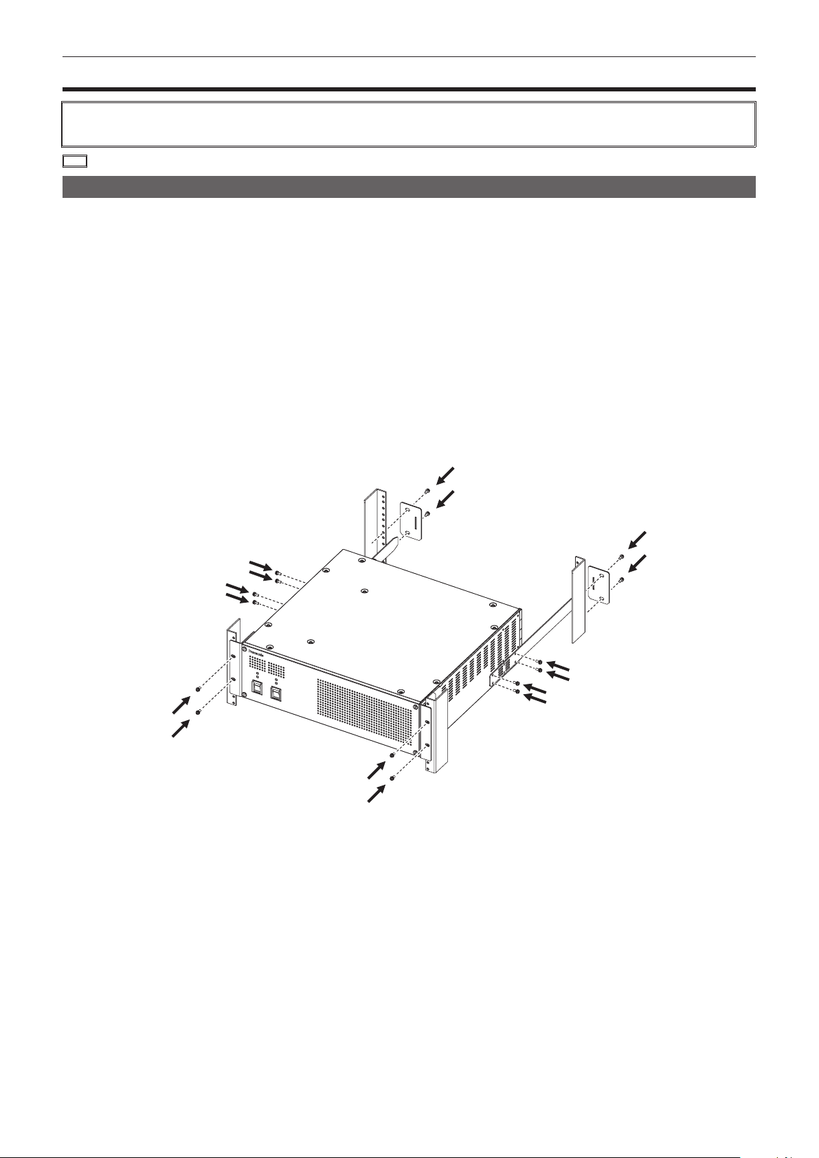
Installing the Main Frame AV‑HS60U1/AV‑HS60U2
When installing or connecting the unit, be sure to ask your dealer. When you want to add the redundant power supply on the Main Frame
AV‑HS60U1, consult your dealer.
r Connecting the power supply
f Connect the <SIGNAL GND> terminal on the rear panel of the unit to the ground of the system.
f When using the Main Frame AV-HS60U1/AV-HS60U2, activate both the power supply 1 and the power supply 2.
An alarm is displayed when there is no AC power input to the power supply 1 and the power supply 2 or when the power switch is set to <OFF>.
(An alarm will not be displayed on the Main Frame AV-HS60U1, because it has only the power supply 1.)
r Handle carefully.
f Dropping the unit or subjecting it to strong impact or vibration may cause trouble and/or malfunctioning.
r Do not allow any foreign objects to enter inside the unit.
f Allowing water, metal items, scraps of food or other foreign objects inside the unit may cause a re and/or electric shocks.
r Choosing the best installation location
f This unit is a device for indoor use only.
f Securely mount the unit on the 19-inch standard rack that complies with the EIA standards (overall depth: 600 mm (23-5/8 inches) or more).
f Securely afxed with screws that match an appropriately sized rack.
f Be sure to attach the rack-mounted rear panel support bracket (accessory) that supports the back part of the Main Frame AV-HS60U1/AV-HS60U2.
(Prepare a support bracket appropriate for the rack if the supplied bracket cannot be attached.)
f Secure sufcient space around the ventilation holes at the front and side of the front cover.
– 12 –

Chapter 2 Installation and Connection (To installation personnel) — Installation (To installation personnel)
f Do not install the unit in a manner in which the unit or cables can be easily damaged.
f Avoid installing the unit where it will be exposed to direct sunlight or to the hot air that is blown out from other products.
f Installing the unit in a very humid, dusty, or vibration-prone location may cause malfunction.
Installing the Control Panel AV‑HS60C1/AV‑HS60C2
When installing or connecting the unit, be sure to ask your dealer. When you want to add the redundant power supply on the Control Panel
AV‑HS60C1, consult your dealer.
r Connecting the power supply
f Connect the <SIGNAL GND> terminal on the rear panel of the unit to the ground of the system.
f When using the Control Panel AV-HS60C1/AV-HS60C2, activate both the power supply 1 and the power supply 2.
An alarm is displayed when there is no AC power input to the power supply 1 and the power supply 2 or when the power switch is set to <OFF>.
(An alarm will not be displayed on the Control Panel AV-HS60C1, because it has only the power supply 1.)
r Handle carefully.
f Dropping the unit or subjecting it to strong impact or vibration may cause trouble and/or malfunctioning.
r Do not allow any foreign objects to enter inside the unit.
f Allowing water, metal items, scraps of food or other foreign objects inside the unit may cause a re and/or electric shocks.
r Choosing the best installation location
f This unit is a device for indoor use only.
f Install the unit on a sufciently strong, stable, and level surface for use.
f Secure a space near the ventilation holes on the front panel of the power unit and on the rear panel of the Control Panel AV-HS60C1/AV-HS60C2 so
that air circulation is not impeded.
In particular, ensure sufcient space between ventilation and wiring when using mounted in a panel or table.
f Avoid installing the unit where it will be exposed to direct sunlight or to the hot air that is blown out from other products.
f Installing the unit in a very humid, dusty or vibration-prone location may cause malfunction.
Installing the Menu Panel AV‑HS60C3
Attach the panel using 4 mounting holes (M4 screw ×4, 75 mm (2-15/16 inches) pitch) on the rear panel of the Menu Panel AV-HS60C3.
For details, refer to “Dimensions of the Menu Panel AV-HS60C3” (page 152).
Attaching the Storage Module AV‑HS60D1 (SSD)
If attached inside the Main Frame AV-HS60U1/AV-HS60U2, register memories of Still and Clip, and project data can be saved in the Main Frame
AV-HS60U1/AV-HS60U2.
For details, refer to the “Installation Guide” of the Storage Module AV-HS60D1 (optional).
NOTE
@@
t When attaching or removing the module, be sure to ask your dealer.
t Before attaching or removing the module, turn off the power, and disconnect the power plug.
t Before coming into physical contact with the Storage Module AV-HS60D1 (optional), touch a grounded metal object with your hand to discharge the
static electricity in your body. A safe way to proceed is to wear an anti-static wrist strap. Touching the option board with static still in your body may
cause malfunction.
t Do not drop the Storage Module AV-HS60D1 (optional) or subject it to strong impact or vibration.
t When attaching or removing the Storage Module AV-HS60D1 (optional), take care not to hurt yourself on the edges or metal parts of the Main Frame
AV-HS60U1/AV-HS60U2.
– 13 –

Chapter 2 Installation and Connection (To installation personnel) — Installation (To installation personnel)
Installing the Chromakey Software AV‑SFU60
If the activation operation is performed using the key code attached to the Chromakey Software AV-SFU60 (optional), chroma key functions of KEY2,
KEY3, and KEY4 can be added. One package contains a single keyer for ME1 and ME2, so three packages are required when adding chroma key
functions to all keyers.
For details, refer to “Read before use” of the Chromakey Software AV-SFU60 (optional).
NOTE
@@
t This function will be available in V2.00.00 or higher.
– 14 –
Chapter 2 Installation and Connection (To installation personnel) — Connection (To installation personnel)
Connection (To installation personnel)
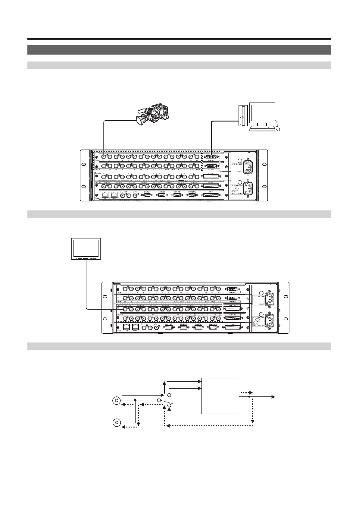
Connecting the imaging systems
<SDI IN 1> to <SDI IN 32>/<DVI‑D IN1>/<DVI‑D IN2> terminals
Connect cameras, VTR, and other external sources.
The SDI input of the Main Frame AV-HS60U1/AV-HS60U2 has a frame synchronizer function, and a non-synchronized SDI signal can be input. To
reduce image delay, set the frame synchronizer function to [Off], send a sync signal to the unit and the input device, and congure a synchronized
system.
Camera
Computer
<SDI OUT 1> to <SDI OUT 16> terminals
Connect the switcher output signal to monitors and other external devices.
HD-SDI monitor
<REF> terminal
Connect the system sync signal from the sync signal generator.
The loop-through output is performed in the external sync mode. If the loop-through output is not going to be used, provide a 75 Ω termination.
Black burst signals are output from both terminals in the internal sync mode.
Sync signal
External sync mode
Internal signal
generator
INT
Internal sync mode
– 15 –

Chapter 2 Installation and Connection (To installation personnel) — Connection (To installation personnel)
Connecting the control systems
Connecting the Main Frame AV‑HS60U1/AV‑HS60U2 and the Control Panel AV‑HS60C1/AV‑HS60C2
Connect the <PANEL> terminal of the Main Frame AV-HS60U1/AV-HS60U2 and the <MAIN FRAME> terminal of the Control Panel AV-HS60C1/
AV-HS60C2 using the supplied LAN cable (CAT5E).
Supplied cable: LAN cable (CAT5E), straight cable, STP (Shielded Twisted Pair), 10 m (32.8 ft)
r Connecting the sub control panel
The second and third sub control panel can be connected to the <LAN> terminal of the Main Frame AV-HS60U1/AV-HS60U2.
When connecting to the second and further sub control panel, a computer for menu operation, or external devices, or when installing at a location where
more length than the supplied LAN cable (CAT5E) (10 m (32.8 ft)) is required, prepare the following cable.
Recommended cable: LAN cable (CAT5E), straight or crossover cable, STP (Shielded Twisted Pair), max. 100 m (328 ft)
NOTE
@@
t Connecting to the second and further sub control panel, computer for menu operation, or external devices will be available in V2.00.00 or higher.
SHOT MEMORY
XPT
CBAUX
ME1ME1 ME1
ME1
ME1
LIN PinP PinP
CHR
BUS
MIX
WIPE
WIPE
4
3
2
1
8
7
6
5
CAMERA
CAMERA
CAMERA
CAMERA
CAMERA
CAMERA
CAMERA
CAMERA
4
3
2
1
8
7
6
5
4
2
1
8
7
6
5
3
CAMERA
CAMERA
CAMERA
CAMERA
CAMERA
CAMERA
CAMERA
CAMERA
4
3
2
1
5
8
7
6
17
15
10
9
CAMERA
CAMERA
STILL1V16CG2V
CG1V14VTR413VTR312VTR211VTR1
10
9
10
9
CAMERA
CAMERA
9
10
SHFT
24
23
22
21
20
BAR
CB1
ME1
CB2
CLIP1V19CLIP1V18STILL2V
RECALL
STORE
DEL
CLIP1
REGISTER
BUS
SHFT
23
24
ME1
BAR22CB221CB120CLIP1V19CLIP1V18STILL2V17STILL1V16CG2V15CG1V14VTR413VTR312VTR211VTR1
RECALL
STORE
DEL
WIPE
0s15f
1s00f
1s00f
1s00f
MIX
ME1
2s00f
CG5V CG6V CAM1CAM2
LIN PinP PinP
LIN
WIPE
WIPE
WIPE
WIPE
1s15f
1s15f
2s00f
2s00f
MIX
ME2
2s00f
CG5V CG6V CAM1CAM2
CG1V CG2V CG3V CG4V
Main control panel
SHOT MEMORY
XPT
CBAUX
ME1ME1 ME1
ME1
ME1
LIN PinP PinP
CHR
BUS
MIX
WIPE
WIPE
4
3
2
1
6
5
CAMERA
CAMERA
CAMERA
CAMERA
CAMERA
CAMERA
CAMERA
4
3
2
1
6
5
4
2
1
6
5
3
CAMERA
CAMERA
CAMERA
CAMERA
CAMERA
CAMERA
CAMERA
4
3
2
1
5
6
15
10
9
8
7
CAMERA
CAMERA
CAMERA
CG1V14VTR413VTR312VTR211VTR1
10
9
8
7
10
9
8
7
CAMERA
CAMERA
CAMERA
9
8
7
10
Sub control panel 1
SHFT
24
23
22
21
20
17
BAR
CB1
STILL1V16CG2V
ME1
CB2
CLIP1V19CLIP1V18STILL2V
RECALL
STORE
DEL
CLIP1
REGISTER
BUS
SHFT
23
24
ME1
BAR22CB221CB120CLIP1V19CLIP1V18STILL2V17STILL1V16CG2V15CG1V14VTR413VTR312VTR211VTR1
RECALL
STORE
DEL
WIPE
0s15f
1s00f
1s00f
1s00f
MIX
ME1
2s00f
CG5V CG6V CAM1CAM2
LIN PinP PinP
LIN
WIPE
WIPE
WIPE
WIPE
1s15f
1s15f
2s00f
2s00f
MIX
ME2
2s00f
CG5V CG6V CAM1CAM2
CG1V CG2V CG3V CG4V
4
3
2
1
8
7
6
5
CAMERA
CAMERA
CAMERA
CAMERA
CAMERA
CAMERA
CAMERA
CAMERA
4
3
2
1
8
7
6
5
4
2
1
8
7
6
5
3
CAMERA
CAMERA
CAMERA
CAMERA
CAMERA
CAMERA
CAMERA
CAMERA
4
3
2
1
5
8
7
6
17
15
10
9
CAMERA
CAMERA
STILL1V16CG2V
CG1V14VTR413VTR312VTR211VTR1
10
9
10
9
CAMERA
CAMERA
9
10
SHOT MEMORY
XPT
CBAUX
ME1ME1 ME1
ME1
ME1
LIN PinP PinP
CHR
BUS
MIX
WIPE
WIPE
SHFT
24
23
22
21
20
BAR
CB1
ME1
CB2
CLIP1V19CLIP1V18STILL2V
RECALL
STORE
DEL
CLIP1
REGISTER
BUS
SHFT
23
24
ME1
BAR22CB221CB120CLIP1V19CLIP1V18STILL2V17STILL1V16CG2V15CG1V14VTR413VTR312VTR211VTR1
RECALL
STORE
DEL
WIPE
0s15f
1s00f
1s00f
1s00f
MIX
ME1
2s00f
CG5V CG6V CAM1CAM2
LIN PinP PinP
LIN
WIPE
WIPE
WIPE
WIPE
1s15f
1s15f
2s00f
2s00f
MIX
ME2
2s00f
CG5V CG6V CAM1CAM2
CG1V CG2V CG3V CG4V
Sub control panel 2
Connecting the Menu Panel AV‑HS60C3
Connect the optional Menu Panel AV-HS60C3 or DVI-D monitor with resolution 1366×768 and USB mouse.
– 16 –

Chapter 2 Installation and Connection (To installation personnel) — Connection (To installation personnel)
DVI-D monitor
r Connecting a computer
Connect to the <LAN> terminal of the Main Frame AV-HS60U1/AV-HS60U2 and control from the Web browser of the computer.
If using Internet Explorer, IE8 or earlier browser versions cannot be used.
For details on the compatible OS and browser, refer to “Required computer environment” (page 9).
NOTE
@@
t This function will be available in V2.00.00 or higher.
Mouse
COM4 (M/S) GPI INCOM3 (M)COM1 (M)REF COM2 (M)LTC IN
SHOT MEMORY
XPT
CBAUX
ME1ME1 ME1
ME1
ME1
LIN PinP PinP
CHR
BUS
MIX
WIPE
WIPE
4
3
2
1
8
7
6
5
CAMERA
CAMERA
CAMERA
CAMERA
CAMERA
CAMERA
CAMERA
CAMERA
CAMERA
6
4
3
2
1
8
7
5
4
2
1
8
7
6
5
3
CAMERA
CAMERA
CAMERA
CAMERA
CAMERA
CAMERA
CAMERA
CAMERA
CAMERA
4
3
2
1
5
6
8
7
17
15
10
9
CAMERA
STILL1V16CG2V
CG1V14VTR413VTR312VTR211VTR1
10
9
10
9
CAMERA
9
10
SHFT
24
23
22
21
20
BAR
CB1
ME1
CB2
CLIP1V19CLIP1V18STILL2V
RECALL
STORE
DEL
CLIP1
REGISTER
BUS
SHFT
23
24
ME1
BAR22CB221CB120CLIP1V19CLIP1V18STILL2V17STILL1V16CG2V15CG1V14VTR413VTR312VTR211VTR1
RECALL
STORE
DEL
WIPE
0s15f
1s00f
1s00f
1s00f
MIX
ME1
2s00f
CG5V CG6V CAM1 CAM2
LIN PinP PinP
LIN
WIPE
WIPE
WIPE
WIPE
1s15f
1s15f
2s00f
2s00f
MIX
ME2
2s00f
CG5V CG6V CAM1 CAM2
CG1V CG2V CG3V CG4V
Main control panel
Computer
External device control
For details on the connection with external devices, refer to “External Interfaces” (page 144).
r GPI I/O
Connect the <GPI IN> terminal, <GPI OUT1> terminal, and <GPI OUT2> terminal of the Main Frame AV-HS60U1/AV-HS60U2, and the <GPI I/O>
terminal of the Control Panel AV-HS60C1/AV-HS60C2 to external devices.
r LAN
Connect the <LAN> terminal of the Main Frame AV-HS60U1/AV-HS60U2 to external devices such as a computer.
f It supports plug-in software.
NOTE
@@
t This function will be available in V2.00.00 or higher.
r Serial port
Connect external devices to the serial ports of the Main Frame AV-HS60U1/AV-HS60U2 (RS-422 ×4), and the serial ports of the Control Panel
AV-HS60C1/AV-HS60C2 (RS-422 ×1, RS-232 ×1) to external devices.
f It supports plug-in software.
– 17 –

Chapter 3 Part Names and Functions
This chapter describes the names, functions, and operations of each part of the unit.
Chapter 3 Part Names and Functions — Main Frame AV‑HS60U1/AV‑HS60U2
Main Frame AV‑HS60U1/AV‑HS60U2
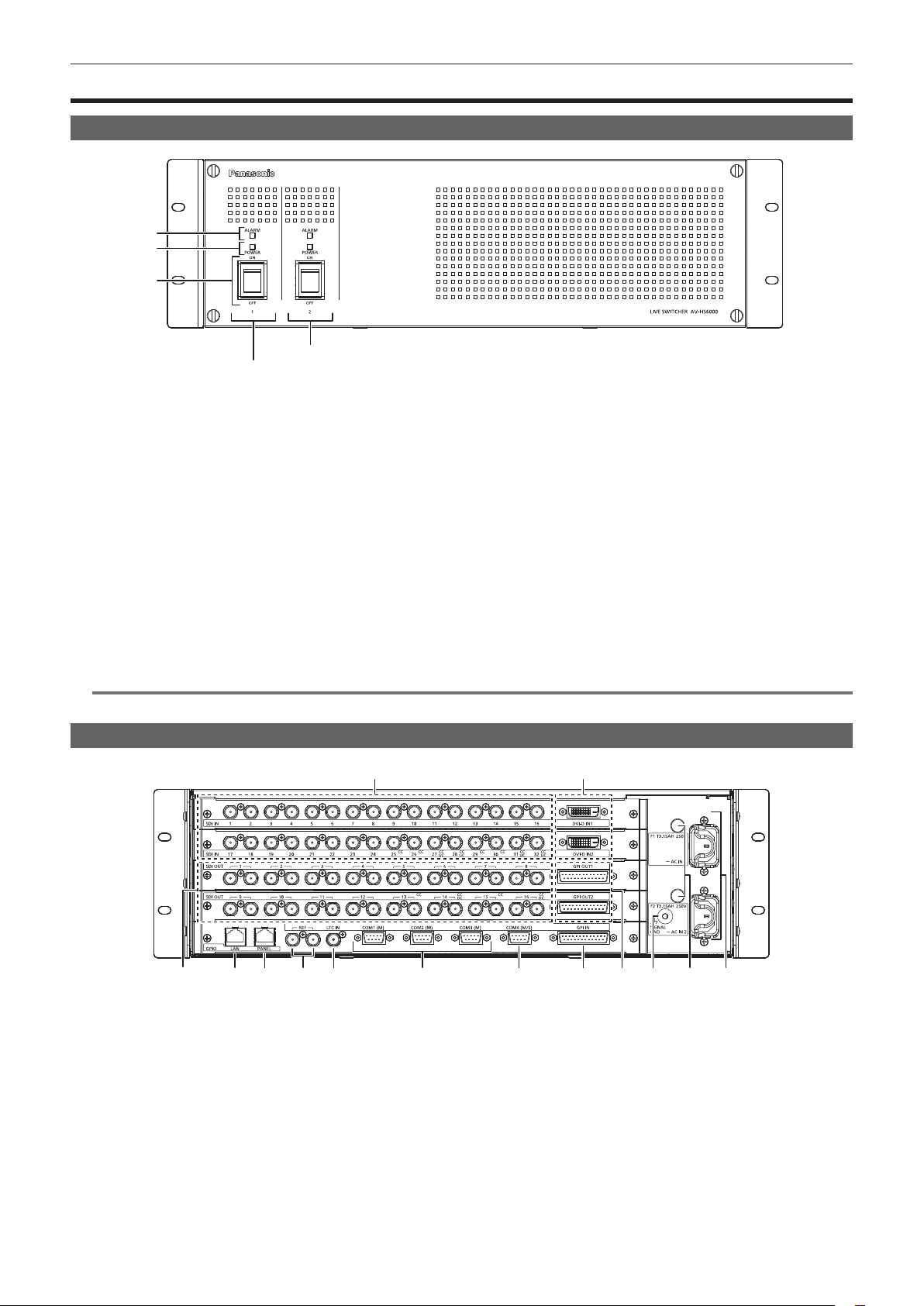
Front panel
1
2
3
Power supply 2
Power supply 1
1 Alarm indicator <ALARM>
Lights up when the cooling fan of the Main Frame AV-HS60U1/AV-HS60U2 has stopped or when there are problems (voltage declines) with the
power supply. In such cases, an alarm message is displayed on the Menu Panel AV-HS60C3. For the redundant power supply model (AV-HS60U2),
an alarm will be displayed if both <POWER> switches of the power supply 1 and the power supply 2 have not turned on.
When an alarm has occurred, details of the problem can be checked from the <SYS> button on the top menu → [MAINTENANCE] → [Alarm] tab.
(page 139)
Alarm status can be output from the alarm output port of the <GPI IN> terminal on the Main Frame AV-HS60U1/AV-HS60U2 to external devices.
f AV-HS60U1 does not have the alarm indicator for the power supply 2.
2 Power indicator <POWER>
Lights up when power is input into the <AC IN 1>/<AC IN 2> terminal and also when the <POWER> switches of the power supply 1 and the power
supply 2 are set to <ON>.
f AV-HS60U1 does not have the power indicator for the power supply 2.
3 <POWER> switch
Turns power on/off.
f The single power supply model (AV-HS60U1) does not have the <POWER> switch for the power supply 2.
f When turning off the power of the redundant power supply model (AV-HS60U2), set both <POWER> switches for the power supply 1 and the
power supply 2 to <OFF>.
NOTE
@@
t When an alarm has occurred, stop using the unit immediately, and be sure to contact your dealer.
Rear panel
1
3 4 5 6 7 8 9 10 11 12 14
1 <SDI IN 1> to <SDI IN 32> terminals (connector: BNC×32/signal: SDI IN)
<SDI IN 25> to <SDI IN 32> terminals are equipped with color correctors.
The <SDI IN 27>/<SDI IN 28>/<SDI IN 31>/<SDI IN 32> terminals are equipped with up-converters.
2 <DVI‑D IN1>/<DVI‑D IN2> terminals (connector: DVI‑D×2/signal: DVI‑D IN)
Connects DVI-D output devices such as a computer using DVI-D cables.
f The DVI-I connector cable cannot be used.
3 <SDI OUT 1> to <SDI OUT 16> terminals (connector: BNC×32/signal: SDI OUT)
Assigns SDI OUT signals from the <IN OUT> button on the top menu → [SDI OUT] → [Assign] tab. (2 distributions each) (page 112)
<SDI OUT 13> to <SDI OUT 16> terminals are equipped with color correctors.
<SDI OUT 14>/<SDI OUT 16> terminals are equipped with down-converters.
4 <LAN> terminal (connector: RJ‑45/signal: 100Base‑TX)
Connects second and further Control Panels AV-HS60C1/AV-HS60C2, menu operation computers, and external devices.
f Images from the Control Panel AV-HS60C1/AV-HS60C2 connected to this terminal cannot be displayed on the Menu Panel AV-HS60C3.
2
13
– 19 –

Chapter 3 Part Names and Functions — Main Frame AV‑HS60U1/AV‑HS60U2
5 <PANEL> terminal (connector: RJ‑45/signal: 100Base‑TX)
Connects the Control Panel AV-HS60C1/AV-HS60C2.
6 <REF> terminal (connector: BNC×2/signal: Genlock)
Loop-through output in the external sync mode. If the loop-through output is not going to be used, provide a 75 Ω termination.
Black burst signals are output from both terminals in the internal sync mode.
7 <LTC IN> terminal (connector: BNC/signal:LTC)
This is the LTC (linear time code) input terminal.
8 <COM1 (M)>/<COM2 (M)>/<COM3 (M)> terminals (connector: D‑sub 9‑pin (female) ×3, inch screw/signal: RS‑422)
Used for master connection of external devices. (page 147)
9 <COM4 (M/S)> terminal (connector: D‑sub 9‑pin (female), inch screw/signal: RS‑422)
Used for master connection/slave connection of external devices. (page 147)
f Master connection and the slave connection can be switched from the <SYS> button on the top menu → [PERIPHERAL] → [General] tab → [MF
COM4] column → [Master/Slave]. (page 136)
10 <GPI IN> terminal (connector: D‑sub 25‑pin (female), inch screw/signal: GPI IN)
Equipped with 18 contact input ports (GPI IN) that control the unit externally, and an alarm output port (ALARM OUT). (page 146)
11 <GPI OUT1>/<GPI OUT2> terminals (connector: D‑sub 25‑pin (female) ×2, inch screw/signal: GPI OUT)
Equipped with 48 output ports (GPI OUT) that output tallies and status information from the unit. (page 145)
12 <SIGNAL GND> terminal (signal: SG)
Connects to the ground of the system.
13 <F1>/<F2> terminals
(Fuse)
14 <AC IN 1>/<AC IN 2> terminals (signal: AC)
Connects one end of the supplied AC cable to this terminal and the other end to the AC outlet. (AC 100 V to 240 V, 50 Hz/60 Hz)
f The supplied AC cable has a 3-pin plug with a grounding terminal. Connect to a 3-pin power outlet which is equipped with a grounding terminal.
f If a 3-point power outlet is not available, be sure to consult your dealer.
NOTE
@@
t For the cable connecting to the <SDI IN 1> to <SDI IN 32> terminals, <SDI OUT 1> to <SDI OUT 16> terminals, <REF> terminal, or <LTC IN>
terminal, use a 5C-FB compliant double-shielded cable.
t For the cable connecting to the <DVI-D IN1>/<DVI-D IN2> terminals, use a double-shielded cable.
t For the cable connecting to the <LAN> terminal, <PANEL> terminal, <COM1 (M)>/<COM2 (M)>/<COM3 (M)>/<COM4 (M/S)> terminals, <GPI IN>
terminal, or <GPI OUT1>/<GPI OUT2> terminals, use a shielded cable.
– 20 –
Chapter 3 Part Names and Functions — Control Panel AV‑HS60C1/AV‑HS60C2
Control Panel AV‑HS60C1/AV‑HS60C2
Operation panel
1 2 3 4 5
4
2
1
3
CAMERA
CAMERA
CAMERA
CAMERA
3
2
1
4
4
2
1
3
CAMERA
CAMERA
CAMERA
CAMERA
4
1
3
2
8
7
6
5
CAMERA
CAMERA
CAMERA
CAMERA
6
8
5
7
8
7
6
5
CAMERA
CAMERA
CAMERA
CAMERA
5
8
7
6
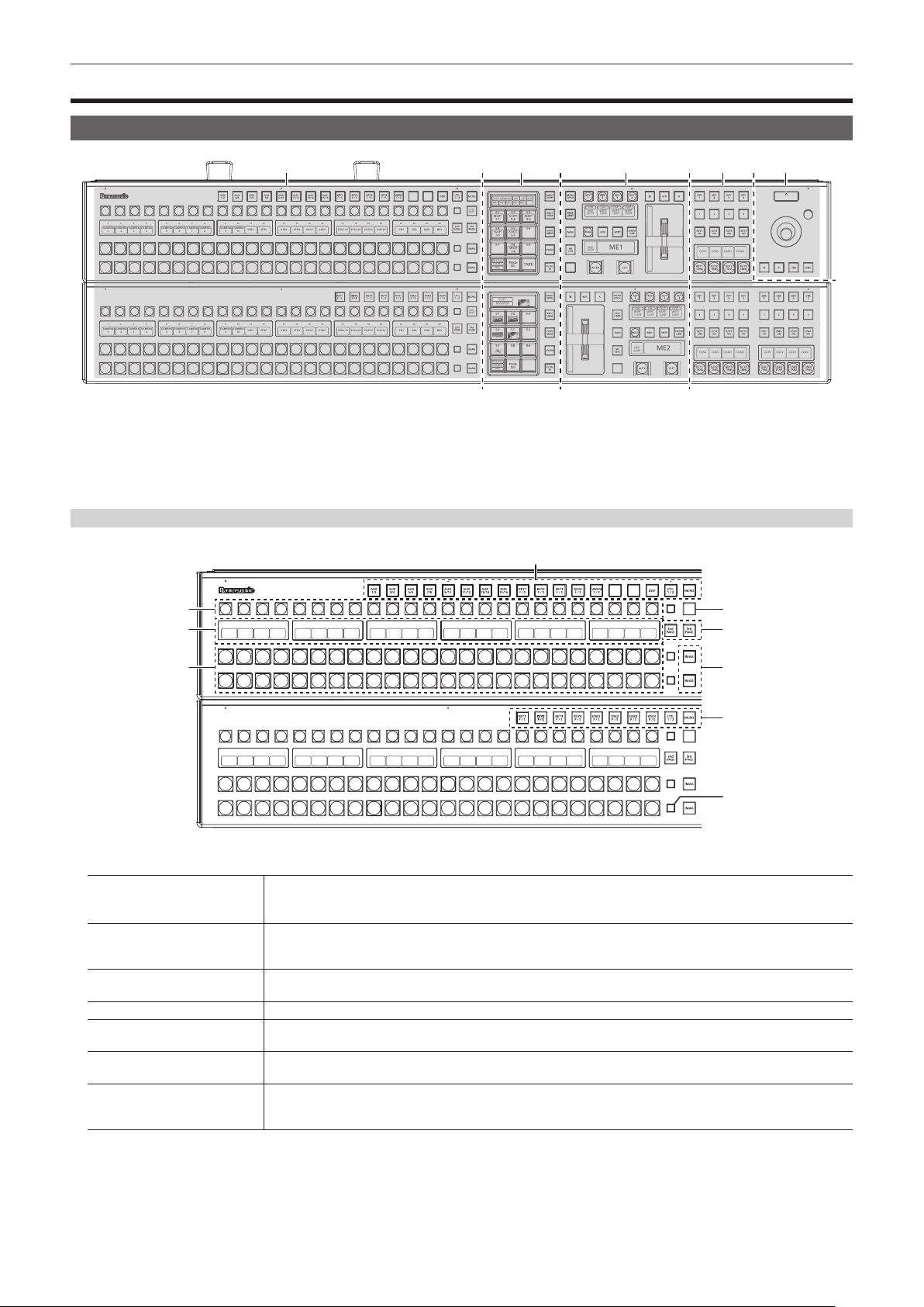
1 Crosspoint area
2 Multi‑selection panel area
3 Transition area
4 KEY/DSK operation area
5 Positioner area
17
10
9
CAMERA
CAMERA
10
9
10
9
CAMERA
CAMERA
9
10
15
STILL1V16CG2V
CG1V14VTR413VTR312VTR211VTR1
17
15
STILL1V16CG2V
CG1V14VTR413VTR312VTR211VTR1
21
20
22
CB1
CB2
CLIP1V19CLIP1V18STILL2V
21
20
22
CB1
CB2
CLIP1V19CLIP1V18STILL2V
SHOT MEMORY
XPT
CB AUX
ME1 ME1 ME1
ME1
ME1
BUS
SHFT
23
24
BAR
ME1
RECALL
STORE
DEL
CLIP1
REGISTER
BUS
SHFT
23
24
BAR
ME1
RECALL
STORE
DEL
CHR
MIX
0s15f
MIX
2s00f
LIN PinP PinP
WIPE
WIPE
1s00f
1s00f
ME1
WIPE
1s00f
CG5V CG6V CAM1 CAM2
LIN
PinP PinP
LIN
WIPE
WIPE
WIPE
WIPE
1s15f
1s15f
2s00f
2s00f
MIX
ME2
2s00f
CG5V CG6V CAM1 CAM2
CG1V CG2V CG3V CG4V
Crosspoint area
2
3
3
2
1
1
3
CAMERA
CAMERA
CAMERA
CAMERA
6
5
CAMERA
CAMERA
CAMERA
6
4
5
9
8
7
CAMERA
CAMERA
9
8
7
CAMERA
12
10
VTR211VTR1
10
4
2
4
4
3
2
CAMERA
1
CAMERA
CAMERA
CAMERA
1
3
2
6
5
CAMERA
CAMERA
CAMERA
4
5
6
9
8
7
CAMERA
CAMERA
9
8
7
1 KEY bus selector buttons (KEY BUS DELEGATION)
Switches functions that can be operated using the KEY bus crosspoint buttons.
<AUX 1/2> to <AUX 15/16>
buttons
<KEY1 F/S> to <KEY4 F/S>
buttons
<VMEM F/S> button
Switches to the source selector buttons for the AUX buses.
f The <AUX 1/2> to <AUX 3/4> buttons have the MIX transition function. (page 122)
f The <AUX 1/2> to <AUX 15/16> buttons have the crosspoint link coupling function. (page 120)
Switches to the source selector buttons for the key ll buses or key source buses.
f Can be congured so that the key ll and key source are linked. The link setting can be made from the <CONF> button
on the top menu → [SOURCE LINK] → [Key Assign] tab → [Master/Slave]. (page 120)
Switches the source selector buttons for the ll buses or source buses of [CLIP1] through [CLIP4] (video memory) and
[STILL1] through [STILL4] (still image memory) input buses.
<DISP> button* Switches to the source selector buttons for the DISP buses to be displayed on the Menu Panel AV-HS60C3.
<UTIL 1/2> button*
<MCRO> button*
<DSK1 F/S> to <DSK4 F/S>
buttons
Switches to the source selector buttons for the utility 1 bus/utility 2 bus that can be inserted to background wipe borders
and backgrounds, and key edges.
Switches to the start button to play back the macro memory assigned to the KEY bus crosspoint buttons. The
assignment can be made from the <MEM> button on the top menu → [MACRO] → [XPT Assign] tab. (page 89)
Switches to the source selector buttons for the DSK ll buses or DSK source buses.
f Can be congured so that the key ll and key source are linked. The link setting can be made from the <CONF> button
on the top menu → [SOURCE LINK] → [Key Assign] tab → [Master/Slave]. (page 120)
* This function will be available in V2.00.00 or higher.
2 KEY bus crosspoint buttons (1 to 24)
Selects the source of the bus which was selected by the KEY bus selector buttons.
Use the <2nd PAGE>/<3rd PAGE> button to select 1 to 96. (page 22)
CAMERA
12
10
VTR211VTR1
10
1
BUS
SHFT
17
16
15
STILL1V
CG2V
CG1V14VTR413VTR3
20
CB1
CLIP1V19CLIP1V18STILL2V
24
22
BAR
ME1
CB2
23
21
5
6
7
1
BUS
SHFT
24
23
22
21
17
16
15
CG2V
STILL1V
CG1V14VTR413VTR3
20
CB1
BAR
ME1
CB2
CLIP1V19CLIP1V18STILL2V
8
– 21 –

Chapter 3 Part Names and Functions — Control Panel AV‑HS60C1/AV‑HS60C2
3 Source name display panels
(This function will be available in V2.00.00 or higher.)
Displays applications of the crosspoint buttons. The display settings of the source name display panels can be made from the <CONF> button on the
top menu → [SOURCE NAME] → [Panel Name] tab. (page 119)
When operating other than macro bus: “crosspoint number” on the upper line, “input source name” on the lower line
When operating macro bus: “macro name” on the upper line, “input source name” on the lower line
4 PGM/A bus crosspoint buttons (1 to 24), PST/B bus crosspoint buttons (1 to 24)
Selects the video signals of the PGM/A bus and PST/B bus.
Use the <2nd PAGE>/<3rd PAGE> button to select 1 to 96. (page 22)
f Bus mode can be selected from the <CONF> button on the top menu → [OPERATE] → [Transition] tab → [Bus Mode] column → [Bus Mode].
(page 46)
5 <BUS SHFT> button
Press the <AUX 1/2> to <AUX 15/16>/<KEY1 F/S> to <KEY4 F/S>/<VMEM F/S>/<UTIL 1/2>/<DSK1 F/S> to <DSK4 F/S> buttons while holding
down the <BUS SHFT> button to switch the bus selection applications.
Example) <AUX 1/2> button
When only the <AUX 1/2> button is pressed, the KEY bus crosspoint buttons are switched to the source selector buttons of the AUX1 bus. When
the <AUX 1/2> button is pressed while the <BUS SHFT> button is held down, the KEY bus crosspoint buttons are switched to the source selector
buttons of the AUX2 bus.
6 <2nd PAGE>/<3rd PAGE> buttons
Enables the KEY bus crosspoint buttons, PGM/A bus crosspoint buttons, and PST/B bus crosspoint buttons to be used from 1 through 96.
f The pages of the buses included in the corresponding ME can be switched at once. To switch pages at individual buses, assign the <2nd
PAGE>/<3rd PAGE> button to the KEY bus crosspoint buttons, PGM/A bus crosspoint buttons, and the PST/B bus crosspoint buttons. (page 118)
Button status
<2nd PAGE> button <3rd PAGE> button
Displayed page
Off Off First page (1-24)
Lit Off Second page (25-48)
Off Lit Third page (49-72)
Lit Lit Fourth page (73-96)
7 <IMAG> button
(This function will be available in V2.00.00 or higher.)
Enables/disables image effects (paint, mono colors, mosaics, defocusing, etc.) to be added to images selected at the PGM/A bus and PST/B bus.
f The setting to enable/disable image effects to be added to images selected at the KEY bus can be made from the <ME1>/<ME2> button on the top
menu → [IMAGE] → [Key1]/[Key2]/[BKGD] tab → [Paint]/[Mono]/[Mozaic/Defocus] column. (page 73)
8 Bus tally
Indicates the output status of the buses. The buses that comprise the on-air tallies will light up.
Multi‑selection panel area
1
CLIP1
REGISTER
2
RECALL
STORE
DEL
1 Mode selection button
Switches functions that can be operated on the multi-selection panel.
<BKGD WIPE> button*
<SHOT MEM> button Registers/recalls/deletes register memories of the shot memory.
<EVNT MEM> button*
<VMEM> button
<PLUG IN> button*
*1 Operations are limited in the version below V2.00.00.
*2 This function will be available in V2.00.00 or higher.
2 Multi‑selection menu panel
When the mode selection button is pressed, the menu to be displayed is switched.
For details, refer to “Basic operations for the multi-selection panel area” (page 36).
1
Selects background wipe preset.
Recalls register memories of the event memory. This button is also used to select register memories during EMEM-LINK
2
transition.
f Registration/editing are performed using the menu.
Records [CLIP1] through [CLIP4] (video memory) and [STILL1] through [STILL4] (still image memory) to the current
frame memories and plays them back.
f When using the Storage Module AV-HS60D1 (optional), register memories can be registered/recalled/deleted on SSD
installed in the Main Frame AV-HS60U1/AV-HS60U2.
2
Used as a plug-in software menu.
– 22 –

Transition area
Chapter 3 Part Names and Functions — Control Panel AV‑HS60C1/AV‑HS60C2
1
7
2
3
4
5
1
6
CHR
MIX
0s15f
MIX
2s00f
LIN PinP PinP
WIPE
WIPE
1s00f
1s00f
ME1
WIPE
1s00f
8
3
9
10
1 Transition target selection buttons (<BKGD>/<KEY1>/<KEY2>/<KEY3>/<KEY4>)
Sets the operation target for the next transition to be executed when the fader lever or <AUTO>/<CUT> button is operated.
2 <MCRO ATCH> button
(This function will be available in V2.00.00 or higher.)
Switches between enabling/disabling macro attach functions assigned to the button of the corresponding ME.
f When set to on, the macro attach function is enabled.
f When pressed and held, the button to which the macro attach function is applied will blink.
3 Status display
Displays the key type (KEY only)/transition type/transition time.
4 <PATT LIMIT> button
Restricts the amount of the background wipe transition for the corresponding ME.
f When set to on, the pattern limit function is enabled.
f Set pattern limit details from the <ME1>/<ME2> button on the top menu → [BKGD] → [Position] tab → [Pattern Limit] column. (page 49)
5 Transition type selection buttons (<NAM>/<MIX>/<WIPE>/<EMEM LINK>)
Switches images while overlapping. During the transition, the output total of the A bus and B bus is kept at 100%.
<MIX> button
<WIPE> button
<EMEM LINK> button Performs transition according to the patterns registered in the event memory. (page 81)
In background transition, the above operation is applied when the <NAM> button is off. If the <NAM> button is on,
images are switched between the A bus and the B bus with non-additive mixing. High luminance images with the A bus
100% and the B bus 100% are output when the fader lever is positioned midway.
Performs transition according to the patterns set in the menu or selected at the wipe preset on the multi-selection panel
area.
6 <ME CHG> button
(This function will be available in V2.00.00 or higher.)
Switches ME of the operation target. (page 122)
When pressed and held, switchable ME is displayed on the ME status display area. When the <MIX> button is pressed while the <ME CHG> is held
down, the operation target will be switched.
7 Wipe direction selection buttons
Selects the wipe direction when executing the background transition. The operation is not performed when the transition is a key.
<N> button Wiping proceeds in the normal direction.
<R> button Wiping proceeds in the reverse direction.
<N/R> button
The normal direction is replaced with the reverse direction (or vice versa) when the transition is completed.
f On/off of the <N>/<R> button is also switched according to the wipe direction.
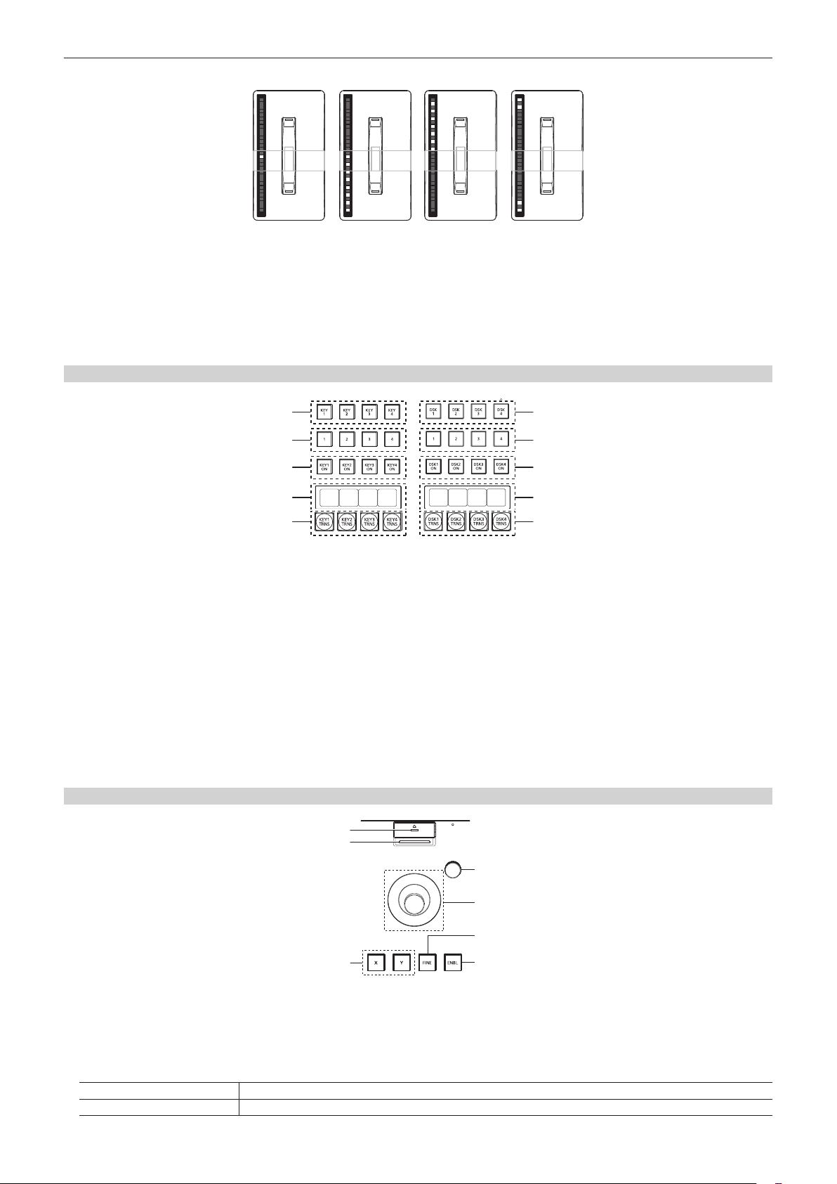
8 Fader lever/transition status
Used to execute background or key transitions. When the lever is moved as far as it will go, the transition is completed. If the fader lever has been
operated during auto transition, auto transition will be switched to manual operation as soon as the fader lever position overtakes the amount of the
transition being executed.
For details on the transition status display, refer to “Transition status display” (page 24).
9 ME status area
Displays the ME of the operations target. Use the <ME CHG> button to switch the ME of the operation target.
10 transition execution button
<AUTO> button
<CUT> button Executes transition instantly.
Automatically executes transition. (Auto transition)
f To set the transition time, select the <ME1>/<ME2> button on the top menu → [BKGD] → [Transition] tab →
[Transition] column → [Time]. (page 47)
– 23 –
Chapter 3 Part Names and Functions — Control Panel AV‑HS60C1/AV‑HS60C2
r Transition status display
Fig. 1 Fig. 2 Fig. 3 Fig. 4
The transition status display at the left side of the fader lever indicates not the lever position but the amount of transition, and also works during auto
transition.
During pattern limitation, the amount of limitation will also be displayed. (Fig. 1)
If the fader lever position and the amount of images do not match after memory playback or auto transition execution, every other display will be
displayed. When displayed at one side (Fig. 2, Fig. 3), push the lever towards the displayed side to make the lever position recognize.
If multiple operations of BKGD and KEY1 to KEY4 are performed in the next transition, both sides may become unmatched. In such a case, the display
will be like Fig. 4, so move the fader lever back and forth to make the lever position recognize.
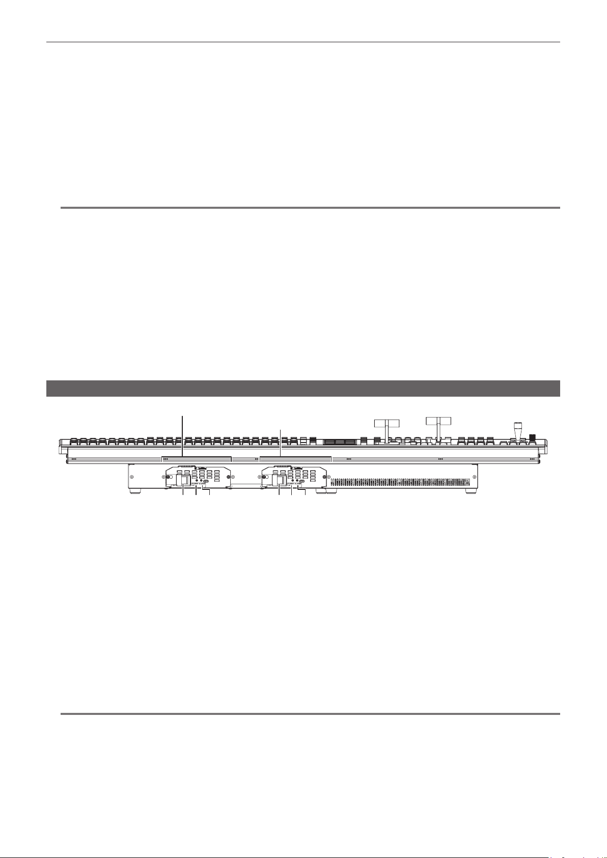
KEY/DSK operation areas
1
2
3
4
CG5V CG6V CAM1 CAM2
CG1V CG2V CG3V CG4V
5
KEY operation area DSK operation area
1 Operation target selection buttons (<KEY1>/<KEY2>/<KEY3>/<KEY4>/<DSK1>/<DSK2>/<DSK3>/<DSK4>)
Selects the operation target for key/DSK preset memory.
Switches target to be displayed in the SEL KEYPVW output. (page 133)
2 Key/DSK preset memory buttons (<1>/<2>/<3>/<4>)
(This function will be available in V2.00.00 or higher.)
Recalls/registers the key preset memory.
f Short press: Recalls data saved to the corresponding button. (Recall)
f Long press: Stores the current key settings to the corresponding button. (Store)
3 <KEY1 ON>/<KEY2 ON>/<KEY3 ON>/<KEY4 ON>/<DSK1 ON>/<DSK2 ON>/<DSK3 ON>/<DSK4 ON> buttons
Executes/cancels each key with a cut transition.
4 Source name display panels
Displays the source name selected for each key.
5 <KEY1 TRNS>/<KEY2 TRNS>/<KEY3 TRNS>/<KEY4 TRNS>/<DSK1 TRNS>/<DSK2 TRNS>/<DSK3 TRNS>/<DSK4 TRNS> buttons
Executes transition with the transition type and transition time for each key set in the menu. (pages 53, 66)
1
2
3
4
5
Positioner area
1
2
4
5
6
3
1 Memory card access LED
Lights up while accessing the memory card.
Do not turn off the power of the unit or eject the memory card while lit. The memory card or data in the memory card may be damaged.
2 Memory card slot
Insert an SD memory card (optional) or an SDHC memory card (optional).
3 Positioner buttons (<X>/<Y>)
<X> button Enables the X-axis operation of the positioner (horizontal direction).
<Y> button Enables the Y-axis operation of the positioner (vertical direction).
7
– 24 –
Chapter 3 Part Names and Functions — Control Panel AV‑HS60C1/AV‑HS60C2
4 Z‑axis dial
Used to set the numeric values at the numeric entry items on the Menu Panel AV-HS60C3.
It corresponds to the third from the left of the rotary encoders on the Menu Panel AV-HS60C3.
5 Positioner
Used to set the numeric values at the numeric entry items on the Menu Panel AV-HS60C3.
f X axis (horizontal direction): Corresponds to the leftmost of the rotary encoders on the Menu Panel AV-HS60C3.
f Y axis (vertical direction): Corresponds to the second from the left of the rotary encoders on the Menu Panel AV-HS60C3.
6 <FINE> button
Changes the amount of change in parameter for the positioner operation.
When set to on, ner adjustments can be made.
7 <ENBL> button
Lit: Enables operations of the positioner and Z-axis dial.
Off: Disables operations of the positioner and Z-axis dial.
NOTE
@@
t This unit detects the position of the positioner and sets the position to the center by the time when the startup is completed after power is turned on.
Do not touch the positioner until the startup of the unit is completed.
r Memory cards
Memory cards used with the unit should conform to SD or SDHC standards.
Be sure to format memory cards using the unit.
Memory cards with the following capacity can be used for the unit. The unit does not support SDXC memory cards.
SD memory card: 8 MB to 2 GB
SDHC memory card: 4 GB to 32 GB
For the latest information not available in the Operating Guide, visit the following website.
http://pro-av.panasonic.net/ (English only)
f Keep the following points in mind when using or storing memory cards.
- Avoid high temperatures/humidities.
- Do not expose to water droplets.
- Avoid electrical charges.
Front panel
Power supply 1
Power supply 2
2 3 2 31 1
1 <POWER> switch (with safety guard)
Turns power on/off.
f The single power supply model (AV-HS60C1) does not have the <POWER> switch for the power supply 2.
f When turning off the power of the redundant power supply model (AV-HS60C2), set both <POWER> switches for the power supply 1 and the
power supply 2 to <OFF>.
2 Power indicator
When power is input into the <AC IN 1>/<AC IN 2> terminal, both <POWER> switches of the power supply 1 and the power supply 2 will light up
when they are set to <ON>.
f AV-HS60C1 does not have the power indicator for the power supply 2.
3 Alarm indicator <ALARM>
Lights up when the cooling fan of the Control Panel AV-HS60C1/AV-HS60C2 has stopped or when there are problems (voltage declines) with the
power supply. In such cases, an alarm message is displayed on the Menu Panel AV-HS60C3. For the redundant power supply model (AV-HS60C2),
an alarm will be displayed if both <POWER> switches of the power supply 1 and the power supply 2 have not turned on.
When an alarm has occurred, details of the problem can be checked from the <SYS> button on the top menu → [MAINTENANCE] → [Alarm] tab.
(page 139)
The alarm status can be output from the <GPI I/O> terminal of the Control Panel AV-HS60C1/AV-HS60C2 to external devices.
f AV-HS60C1 does not have the alarm indicator for the power supply 2.
NOTE
@@
t When an alarm has occurred, stop using the unit immediately, and be sure to contact your dealer. Continuous use of the unit even after an alarm has
occurred could damage the unit.
– 25 –

Chapter 3 Part Names and Functions — Control Panel AV‑HS60C1/AV‑HS60C2
Rear panel
1
MAIN FRAME GPI I/O COM1 (M) COM2 (RS-232)
MENU PANEL
2 3 54 6 7 8 9
1 <AC IN 1>/<AC IN 2> terminals (signal: AC)
Connects one end of the supplied AC cable to this terminal and the other end to the AC outlet. (AC 100 V to 240 V, 50 Hz/60 Hz)
f The supplied AC cable has a 3-pin plug with a grounding terminal. Connect to a 3-pin power outlet which is equipped with a grounding terminal.
f If a 3-point power outlet is not available, be sure to consult your dealer.
2 <MAIN FRAME> terminal (connector: RJ‑45/signal: 100Base‑TX)
Connects to the <PANEL> terminal or <LAN> terminal of the Main Frame AV-HS60U1/AV-HS60U2.
f When connected to the <LAN> terminal, no video will be displayed on the Menu Panel AV-HS60C3.
3 <MENU PANEL> terminal (connector: DVI‑D/signal: independent signal)
Connects the Menu Panel AV-HS60C3.
f Cannot be used concurrently with a DVI monitor (computer) connected to the <DVI-D> terminal. Select with the display selector switch.
f This is the dedicated interface for the Menu Panel AV-HS60C3. Do not connect with DVI output devices.
4 Display selector switch
Switches the terminal to be used to the <MENU PANEL> terminal or <DVI-D> terminal depending on the connected device.
Switch this when the power is off. Output will not be performed properly if switched with the power turned on. Restarting of the unit will be necessary.
Set the power to <OFF>, and then set it back to <ON>.
5 <DVI‑D> terminal (connector: DVI‑D/signal:DVI OUT)
Connects the DVI monitor (computer) used for the menu display.
f Monitor resolution: 1366×768 compatible monitor
f Cannot be used concurrently with the <MENU PANEL> terminal. Select with the display selector switch.
6 <USB> terminal (connector: USB (type A, female)/signal: USB)
Used for the menu operation of the DVI monitor (computer).
f Cannot be used for the Menu Panel AV-HS60C3.
7 <COM1 (M)> terminal (connector: D‑sub 9‑pin (female), inch screw/signal: RS‑422)
Used for master connection of external devices. (page 147)
8 <COM2 (RS‑232)> terminal (connector: D‑sub 9‑pin (male), inch screw/signal: RS‑232)
Used to control external device. (page 147)
9 <GPI I/O> terminal (connector: D‑sub 25‑pin (female), inch screw/signal: GPI)
Equipped with 8 contact input ports (GPI IN) that control the unit externally, 10 output ports (GPI OUT) that output tallies or status information from
the unit, and an alarm output port (ALARM OUT). (page 146)
10 <F1>/<F2> terminals
(Fuse)
11 <SIGNAL GND> terminal (signal: SG)
Connects to the ground of the system.
NOTE
@@
t For the cable connecting to the <DVI-D> terminal, use a double-shielded cable.
t For the cable connecting to the <MAIN FRAME> terminal, <COM1 (M)>/<COM2 (RS-232)> terminal, and <GPI I/O> terminal, use a shielded cable.
DVI-D USB
10 11
– 26 –
Chapter 3 Part Names and Functions — Menu Panel AV‑HS60C3
Menu Panel AV‑HS60C3
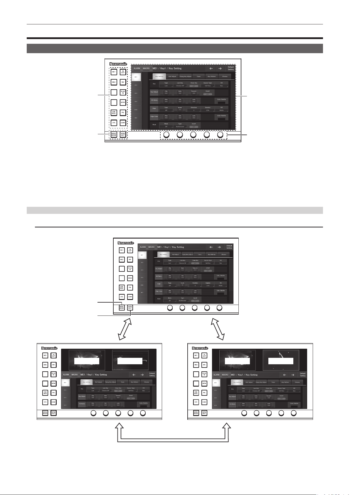
Operation panel
1
2
1 Top menu buttons (<ME1>, <ME2>, <DSK MISC>, <SYS>, <IN OUT>, <MV>, <PLUG IN>, <MEM>, <PRJ>, <CONF>)
Selects the rst hierarchy of the menu.
2 Split‑screen buttons (<MENU MODE>, <WFM VECT>)
Switches the display of the menu screen.
For details, refer to “Split display of the menu screen” (page 27).
3 Menu screen
4 Rotary encoders
When the rotary encoder is turned, the numeric values of the number button focused on the menu can be changed.
When the rotary encoder is double-clicked, the numeric values of the number button focused on the menu will return to the default settings.
3
4
Split display of the menu screen
NOTE
@@
t This function will be available in V2.00.00 or higher.
1
2
<MENU MODE> button
PICT VECTPICTWFM
<WFM VECT> button
1 <MENU MODE> button
Each time this button is pressed, the full screen display and split display (PICT, WFM/VECT, menu) of the menu are switched.
The display content is as follows when the display of the Menu Panel AV-HS60C3 is split.
<MENU MODE> button
– 27 –

Chapter 3 Part Names and Functions — Menu Panel AV‑HS60C3
Display position Display content
Upper left Images selected in the DISP bus are displayed.
Upper right The WFM (waveform monitor) or VECTOR (vectorscope) for the video selected in the DISP bus is displayed.
Bottom The menu will be displayed.
2 <WFM VECT> button
Each time the button is pressed when the menu display is split, the WFM (waveform monitor) and VECTOR (vectorscope) displayed at the upper
right of the screen are switched.
Rear panel
1
1 <CONTROL PANEL> terminal (connector: DVI‑D/signal: independent signal)
Connects the Control Panel AV-HS60C1/AV-HS60C2.
f This is the dedicated interface for connection with the Control Panel AV-HS60C1/AV-HS60C2 (optional). Do not connect with DVI output devices.
– 28 –

Chapter 4 Preparations
This chapter describes basic operations and matters to be performed prior to use.

Chapter 4 Preparations — Turning power on/off
Turning power on/off
Turning power on
Set the <POWER> switches of the Main Frame AV‑HS60U1/AV‑HS60U2 and the Control Panel AV‑HS60C1/AV‑HS60C2 to <ON>.
1
f For the redundant power supply model (AV-HS60U2, AV-HS60C2), set both <POWER> switches of the power supply 1and the power supply 2 to
<ON>.
f The power indicator will light up when power is supplied.
Turning power off
Set the <POWER> switches of the Main Frame AV‑HS60U1/AV‑HS60U2 and the Control Panel AV‑HS60C1/AV‑HS60C2 to <OFF>.
1
f For the redundant power supply model (AV-HS60U2, AV-HS60C2), set both <POWER> switches of the power supply 1and the power supply 2 to
<OFF>.
f The power indicator will go off when power is cut off.
NOTE
@@
t Do not turn off the power when accessing the memory card or the Storage Module AV-HS60D1 (optional). Data in the memory card may be damaged.
t When set to [Resume Data] from the <SYS> button on the top menu → [MAINTENANCE] → [Boot] tab → [Boot Select] column, normally the unit will
start up with the settings as they were when power was cut off, except image data of the VMEM (video memory). (page 140)
Note that, in the following items, the changed settings will be backed up at approximately 60-second intervals in the non-volatile memory, and the
settings at the time of shutdown will be restored, but the settings changed within approximately 60 seconds before turning off the power may not be
updated. To update securely, do not change settings within approximately 60 seconds before turning off the power.
- Background wipe preset (This function will be available in V2.00.00 or higher.)
- Key source preset (This function will be available in V2.00.00 or higher.)
– 30 –
 Loading...