

Page 1
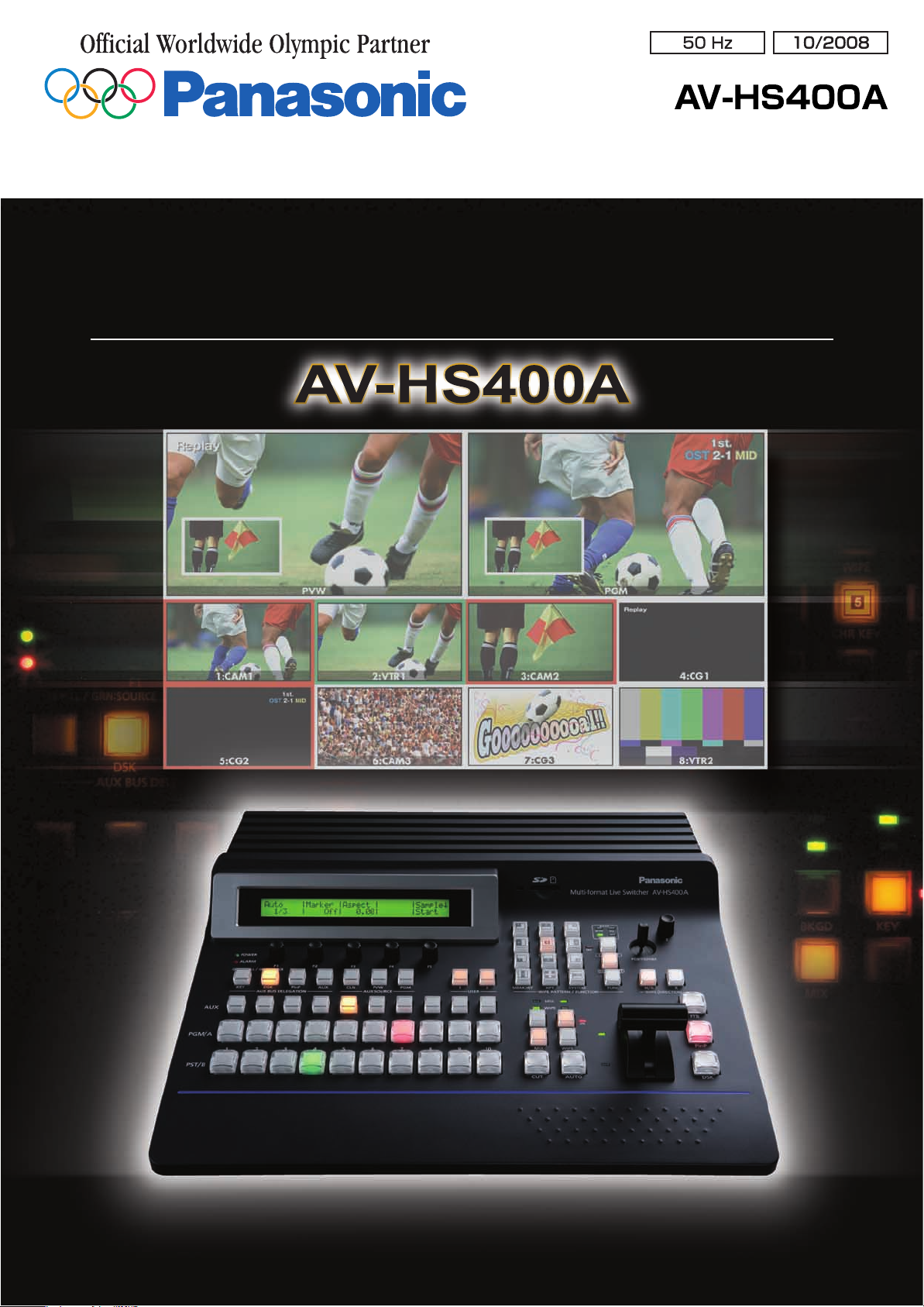
Multi-formatLiveSwitcher
Compact, High-performance, Multi-format Live Switcher
with Multi-view display
Page 2
Introducing the AV-HS400A with new and
enhanced capabilities!
HD Integrated Camera
AW-HE100
Multi-purpose Camera
AK-HC1500
AK-MC1800
Multi-format HD/SD Compatibility for Worldwide Use
Compatibility with various HD/SD formats will help you meet changing production
needs as video moves towards HD on a global scale. The AV-HS400A lets you upconvert and mix SD signals with HD, to provide an easy transition to full HD
production. The AV-HS400A is compatible with virtually all common input devices.
Compatible formats
1080/59.94i , 1080/50i ,
H D
720/59.94p , 720/50p
480/59.94i , 576/50i
S D
Built-in Frame Synchronizers for Versatile Operation
Each input features a built-in 10-bit Frame Synchronizer for smooth switching, even with asynchronous sources,
such as DVDs or satellite feeds. Reference (black burst) signal outputs are provided to enable synchronization
with external systems. The main unit and control panel are integrated in a compact body, ideal for small studios and
mobile production.
AC 220 V to 240 V power supply.
*
• The unit is not waterproof so please avoid direct contact with water.
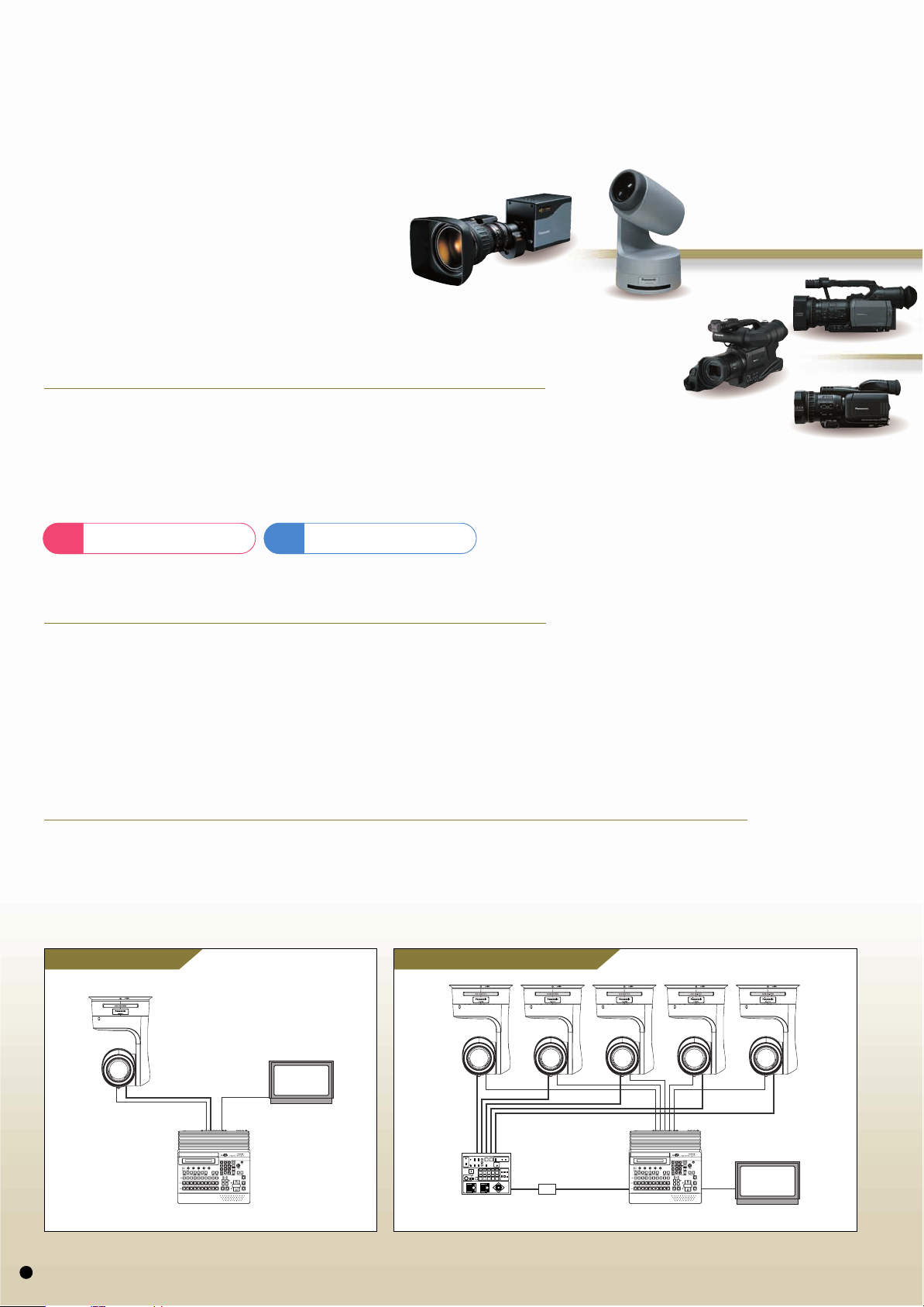
Remotely control the HD integrated camera AW-HE100 and pan-tilt heads
Directly connecting the AW-HE100 3CCD integrated pan/tilt/zoom camera or a Panasonic camera/pan-tilt head*
allows control over pan, tilt, zoom, and focus using the AV-HS400A's positioner.
Moreover, by also connecting a Panasonic control panel** you can switch between and operate up to
5 cameras and pan-tilt heads*.
Compatible models: AW-PH400/AW-PH405/AW-PH360.
*
Direct connections Multiple camera connections
HD Integrated Camera
AW-HE100
Compatible models: AW-RP655/AW-RP555.
**
*
HD Integrated Camera
AW-HE100
RS-422
Video Signal
Multi-Format Live Switcher
AV-HS400A
2
Monitor
Pan-tilt Control Panel
AW-RP555/RP655
RS-422/232C
Converter
RS-422
Video SignalRS-422
Multi-Format Live Switcher
AV-HS400A
Monitor
Page 3
Worldwide Production
Memory Card Camera-Recorder
Compatible with HD/SD cameras
worldwide.
Sports Arena
News Magazine Show
Educational Solution
Concert Hall
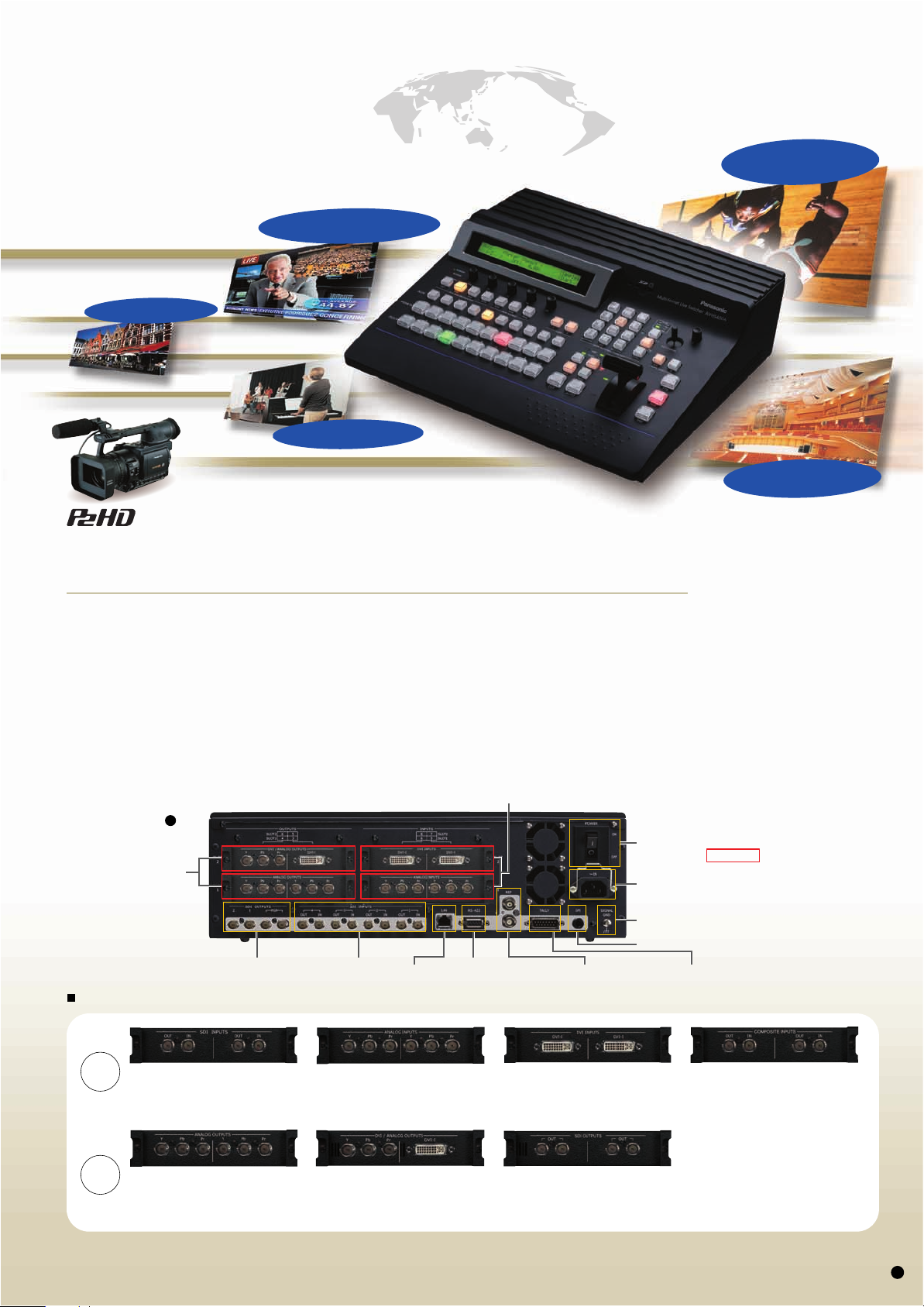
SDI Standard Compatible, with up to 8 Video Inputs and Outputs.
• Standard equipment includes 4 HD/SD-SDI inputs and outputs*.
• Optional input and output expansion boards (sold separately) include:
Input: Addition of up to 4 HD/SD-SDI inputs, up to 4 HD/SD analog components, up to 4 HD/SD analog composite,
or up to 4 DVI-I**. Moreover, each optional input board is equipped with an up-converter.
Output: Addition of up to 4 SDI, 4 Analog Component, and 2 DVI-I
• Tally outputs for up to 8 cameras for extra convenience when operating as a live switcher.
• RS-422 compatible (GVG protocol) control jack.
Two interfaces assignable as PGM,PVW, AUX, multi-screen, and keyout.
*
Compatible with XGA (1024x768), WXGA (1280x768), SXGA (1280x1024), WSXGA+ (1680x1050)
***
Digital output only.
****
Rear
Option Slot x 2
(OUTPUTS)
SDI OUTPUTS
Compatible with XGA, WXGA, SXGA.
**
SDI INPUTS RS-422 Interface
, UXGA (1600x1200)****, WUXGA (1920x1200)****.
****
Option Slot x 2 (INPUTS)
Option Boards You can expand inputs/outputs to match your requirements.
***
outputs, with a maximum of 8 total outputs.
POWER
Switch
Optional boards enable expansion of
Power inlet
Ground
GPI Input
Reference(REF) Input/BB OutputLAN Port
inputs/outputs (up to two of each).
The photography at left is shown with
the AV-HS04M3 (top right)/AV-HS04M2
(bottom right)/ AV-HS04M5 (top left)/
AV-HS04M4 (bottom left) added.
TALLY Output
INPUTS
OUTPUTS
SDI INPUTS BOARD
AV-HS04M1
• INPUTS : HD/SD-SDI x2
(BNC)(Built-in Up-converter)
ANALOG OUTPUTS BOARD
AV-HS04M4
• OUTPUTS : Analog Component x2
(Y/Pb/Pr)
ANALOG INPUTS BOARD
AV-HS04M2
• INPUTS : HD/SD Analog Component x2
(Y/Pb/Pr)(Built-in Up-converter)
DVI/ANALOG OUTPUTS BOARD
AV-HS04M5
• OUTPUTS : DVI-I x1, Analog Component x1
(Y/Pb/Pr)
DVI INPUTS BOARD
AV-HS04M3
• INPUTS : DVI-I x2 (Built-in Scaler) • INPUTS : Analog Composite x2
SDI OUTPUTS BOARD
AV-HS04M7
• OUTPUTS : HD/SD-SDI x2
(Each one has 2 outputs)(BNC)
(Built-in Down-converter)
*
ANALOG COMPOSITE INPUTS BOARD
AV-HS04M6
(Built-in Up-converter)
AV-HS04M6/HS04M7 is exclusively for the
*
AV-HS400A.
The AV-HS400 must be upgraded to use the
AV-HS04M6/HS04M7. For details, please contact
your local Panasonic reseller or representative.
*
3
Page 4

Key Features
Multi-system compatibility for extra flexibility
It's compact with all the functions you need
The main unit and control panel are integrated in a compact body.
Cross-point Buttons for AUX Bus Only
Selects CLN, PVW and PGM material that is selectable
with the AUX bus only.
Rotary Encoder F1-F5
Sets parameters displayed
in the menu.
LCD
Displays settings menu.
POWER Indicator
ALARM Indicator
AUX BUS DELEGATION
Buttons
Switches AUX Bus
Crosspoint button application
between KEY, DSK and PinP
buses.
KEY/AUX Bus
Cross-point row
Select the source of the bus
switched with the KEY/AUX
Bus Cross-point row.
PGM/A Bus
Cross-point row
Select the PGM/A-Bus
video signal.
USER Assignable Buttons
Some functions from the menu can be
assigned to these two buttons.
SD Memory Card Section
Still images (JPEG, BMP) recorded on
an SD Memory Card can be used as
background or key images.
SD Memory Cards can also be used to
store frame memory images and settings data.
Image file transfer via LAN
Compatible with JPEG/TIFF/PNG/
GIF/BMP.
*
WIPE PATTERN/FUNCTION
Selection Buttons
Pattern Page Indicator
Lights indicate wipe, squeeze, slide
or 3D.
Encoder for Adjustment(Z)
In conjunction with the positioner (X, Y),
used to set PinP and wipe location,
chroma key range and other parameters.
POSITIONER(X,Y)
WIPE PATTERN/FUNCTION
Mode Selection Buttons
Selects from background wipe,
KEY wipe or FUNCTION for
WIPE PATTERN/FUNCTION
Selection buttons.
WIPE DIRECTION Selection
Buttons
Independent Transition
Execution Buttons
Switches FTB (Fade-to-Black),
PinP and DSK ON/OFF.
KEY ON/OFF or disable can be
set in the FTB menu.
Fader Lever
SD Memory Card is not included.
*
Comes with dedicated software.
*
PST/B Bus Cross-point row
Select the PST/B-Bus video signal.
Next Transition Selection Buttons
Select transition image from background and key.
Transition Type Selection Buttons
Selects the transition type option, selected with,
Next Transition selection buttons for background and KEY.
• MIX - Switches A-/B-bus images while overlapping.
• WIPE - Performs transition using the pattern selected with the Wipe Pattern Selection button.
4
MIX/WIPE Selection Status Indicator
Indicates background and
KEY transition type selection status.
Bus Tally Indicator
Indicates A-, B-Bus output status.
KEY ON Status Indicator
Transition Execution Buttons
• AUTO - Executes automatic transition at a set time.
• CUT - Executes instant transition.
Page 5

in the field and studio.
for superb results.
Use the Multi-view Display Function to Preview
Materials and Production Screen on a Single Monitor
Multi-view display enables simultaneous split-screen preview with a single monitor, so you can reduce
the number of monitors required. Split-screen segments labels may now be selected or edited.
Labels may also be turned off or adjusted for 5 levels of brightness. The label background "band" and
frame outline may also be turned of, and the frame brightness is adjustable through 5 levels.
Example of an AV-HS400A monitor system
Simultaneous split-screen preview
with a single monitor.
Selectable Split-screen Quantity
and Location
• The number of split-screens can selected from 10,8, and 4.
• Display of red/green tally indications in frame can be displayed.
• Split-screen labels may customized or selected from menus.
• When splitting screens into 10/8 sections, the upper 2 windows
may be selected from PGM/PVW/AUX/BUS/KEYOUT images.
Example of conventional monitor system
Connection of separate monitors is required
for each input, PVW and PGM.
The image shows loop-through outputs connected to switcher inputs.
*
Ten Split Pictures (images)
Eight Split Pictures (images)
Four Split Pictures (images)
5
Page 6

Key Features
Multiple Effects for Stunning Results
In addition to standard wipe patterns, the DVE allows you to utilize squeeze, slide effects, and different types of 3D. The 3D DVE effects (i.e. page turn)
are also applicable to the key function. Keyer functions include a luminance key, chroma key, and DSK. Furthermore, the AV-HS400A offers an
additional, even greater range of visual effect key functions brought to life with the flying key function, enabling easy key position and size adjustment.
Enhanced key functions include omnidirectional edge control in 45 degree increments, and a simplified 2nd PiP (Picture-in-Picture.)
A total of 43 effects offer great creative flexibility
WIPE SQ (Squeeze)
Switching between 12 wipe patterns. Switching between 11 types of squeeze including center, top and bottom.
(images:pattern4) (images:pattern4)
SQ SQ
SQ
123
456
789
10 11 12
SL SL
1
SL SL
456
SL SL SL
789
No Pattern No Pattern No Pattern
10 11 12
23
*
SL
*
Key transition only.
1
SQ SQ SQ
456
SQ SQ SQ
789
SQ
10 11 12
23
No Pattern
3D (3 Dimension)SL (Slide)
Switching between 3D effects such as page turn and rotate.Switching between up, down, left, right and diagonal slide effects.
123
456
More variegated visual
789
10 11 12
effects are offered by
addition of 3D DVE effect
to the key function.
SQ
(images:pattern1) (images:pattern4)
Chroma key for broadcast quality composite images Example of
High-quality chroma key for broadcast and commercial production applications.
Chroma key material Background material
6
After composition
composite effect
WIPE
PiP
DSK
(images)
Page 7

System Examples
Ready for broadcast and
studio production
applications.
HD-SDI camera environment
(with Genlock)
=Option Boards
SDI INPUTS (AV-HS04M1)
SDI INPUTS (AV-HS04M1)
ANALOG OUTPUTS (AV-HS04M4)
Ideal for use with simple
systems at CATV stations,
schools and other locations.
HD camera environment
(no Genlock): Using the HD
Analog component option
=Option Boards
DVI INPUTS (AV-HS04M3)
ANALOG INPUTS (AV-HS04M2)
DVI/ANALOG OUTPUTS (AV-HS04M5)
Signal Generator
Multi-format
Camera
AK-HC3500
Multi-purpose
Camera
AK-HC1500
AK-HC1800
Inputs 5 to 8 can also be
*
upconverted to SD-SDI.
HD VTR
(Spare Line)
HD VTR
(Main Line)
HD Integrated
Camera
AW-HE100
Multi-purpose
Camera
AK-HC1500
AK-HC1800
or
HD VTR P2 Mobile
PC
IN(REC)
OUT(Monitor)
IN(REC)
OUT(Monitor)
OUT(PLAY)
IN(REC)
DVI or VGA
B.B.
HD-SDI
HD-SDI
HD-SDI
HD-SDI
HD(SD)-SDI
HD(SD)-SDI
HD(SD)-SDI
HD(SD)-SDI
HD Analog Component
HD Analog Component
HD-SDI
HD-SDI
HD-SDI
HD Analog
Component
AV-HS400A
HD-SDI (Ach)
HD-SDI (Bch)
HD-SDI (Ach)
HD-SDI (Bch)
HD Analog Component
DVI
AV-HS400A
HD-SDI
HD-SDI Monitor
HD-SDI Monitor
PC Monitor
HD-SDI Monitor
PDP
PDP
or
Projector
Provides the flexibility
required for facilities moving
from SD to HD production.
1. A combined HD/SD-SDI and
HD/SD analog component
environment without Genlock.
=Option Boards
ANALOG INPUTS(AV-HS04M2)
SDI INPUTS(AV-HS04M1)
DVI/ANALOG OUTPUTS(AV-HS04M5)
ANALOG OUTPUTS(AV-HS04M4)
2. A combined HD/SD-SDI and
analog composite environment
without Genlock.
=Option Boards
ANALOG COMPOSITE INPUTS
(AV-HS04M6)
SDI OUTPUTS (AV-HS04M7)
Analog Material (Optional Input)
SD Analog
HD Analog
SDI Material (Optional Input)
SD-SDI
HD-SDI
SDI Material (Standard Input)
SD-SDI
HD-SDI
Multi-purpose
Camera
AK-HC1500
AK-HC1800
Convertible Camera
AW-E350/E650/E750/E860
SD VTR
SD Use HD Use
Up-Converter
Up-Converter
Analog Component
HD/SD-SDI
HD/SD-SDI
HD-SDI
HD-SDI
SD Analog Composite
SD Analog Composite
Analog Component
DVI
AV-HS400A
HD/SD-SDI
AV-HS400A
HD-SDI
SD-SDI
SD-SDI
HD/SD Analog Component
Monitor
PC Monitor
HD/SD-SDI Monitor
HD-SDI Monitor
SD VTR
SD-SDI Monitor
7
Page 8

Specifications
Video processing
M/E
Input
Output
Dimensions
Video format
Video processing
Video
Reference
Video
Reference
SD (576/50i, 480/59.94i),
HD (1080/59.94i, 1080/50i, 720/59.94p, 720/50p)
1M/E
Y:Cb:Cr, 4:2:2 10 bit
RGB, 4:4:4 8 bit
Standard: Four inputs (HD/SD-SDI)
Option: A maximum of four inputs (Up to 2 input boards (each board
offering 2 inputs) for each of the following 4 types of boards may be
added: HD/SD-SDI x 2, HD/SD-analog component x 2,
analog composite x 2, DVI-I x 2.)
Black burst/TRI (loop through) x 1
Standard: Four outputs (PGM x 2, general-purpose x 2,
each HD/SD-SDI )
Option: A maximum of four outputs (general-purpose x 4)
(Up to 2 output boards (each board offering 2 outputs) for the
following 3 types of boards may be added: analog component x 2,
DVI-I/analog component x 1 each, HD/SD-SDI x 2).
Loop through x 1 (Genlock)/
Black burst x 2 (internal synchronization)
WIPE/DVE
Transition
KEYER
PinP
Interface
Removable media
Humidity
Operating temperature
Power Supply / Power consumption
Dimensions (W x H x D)
Weight
Features and specifications in this document are subject to change without notice due to continual improvements.
*
Pattern
Transition method
Transition type
Key source
Key fill
Key mode
Transition method
Transition type
Serial (EDITOR)
Tally output
GPI
LAN
SD memory card slot
WIPE x 12, Squeeze x 11, SLIDE x 8, 3D DVE x 12 (3 directions)
Selection with key transition is possible independently of background.
FADER, AUTO
Cut, mix, wipe (including DVE), background and key can be selected.
BUS
BUS, MATTE
Linear key, Lum key, Chroma key (Key only), Full key (Key only)
AUTO (PinP only)
MIX
D-sub9pin x 1: RS-422 (GVG protocol compatible),
for controlling a pan-tilt system
D-sub15pin x 1, open collector output
ø 3.5 Stereo mini jack
RJ45, 10 Mbps x 1
1 (for transferring still image files and providing an upgrade capability)
10 % to 90 % (no condensation)
0 ˚C to +40 ˚C
AC 220 V to 240 V, 50 Hz/60 Hz / Approx. 98 W
420 mm x 132 mm x 408 mm (excluding protrusions)
Approx. 6.4 kg: without options
Approx. 7.2 kg: with options
132 mm
22 mm
SD Logo is a trademark.
408 mm
420 mm
AV-JECHS400A08
Printed in Japan
 Loading...