

Page 1
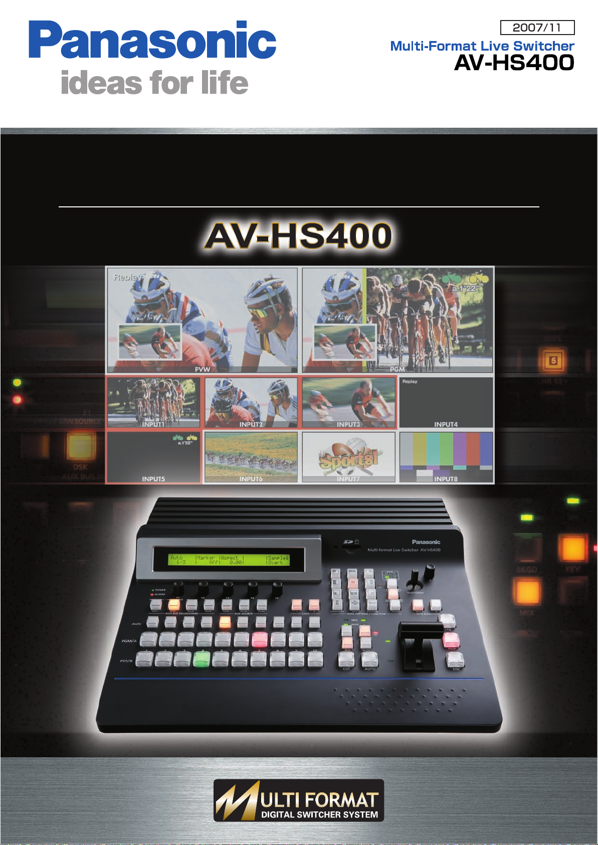
Compact, High-Performance, Multi-Format Live Switcher
with Multi-view display
Page 2

Full Production Quality from
Compact 1M/E Digital Video Switcher
News Magazine Show
Memory Card Camera-Recorder
HD-SDI Multi-purpose
Camera
AK-HC1500
Memory Card Camera-Recorder
Worldwide Production
Educational Solution
Memory Card Camera-Recorder
Memory Card Camera-Recorder
Multi-Format HD/SD Compatibility for Worldwide Use
Compatibility with various HD/SD formats will help you meet changing production
needs as video moves towards HD on a global scale.
The AV-HS400 lets you up-convert and mix SD signals with HD,
to provide an easy transition to full HD production.
The AV-HS400 is compatible with virtually all common input devices.
Built-in Frame Synchronizers for Versatile Operation
Each input features a built-in 10-bit Frame Synchronizer for smooth switching,
even with asynchronous sources, such as DVDs or satellite feeds.
Reference (black burst) signal outputs are provided to enable synchronization
with external systems.
The main unit and control panel are integrated in a compact body,
ideal for small studios and mobile production.
AC 220 V to 240 V power supply.
*
¥ The unit is not waterproof so please avoid direct contact with rain and water.
Versatile Support
for Remote Production
Compatible formats
1080/59.94i , 1080/50i ,
HD
720/59.94p , 720/50p
480/59.94i , 576/50i
SD
The multi-format logo indicates a model that supports
*
two or more formats including the HD format.
2
Page 3
Compatible with HD/SD cameras
worldwide.
Sports Arena
Hall
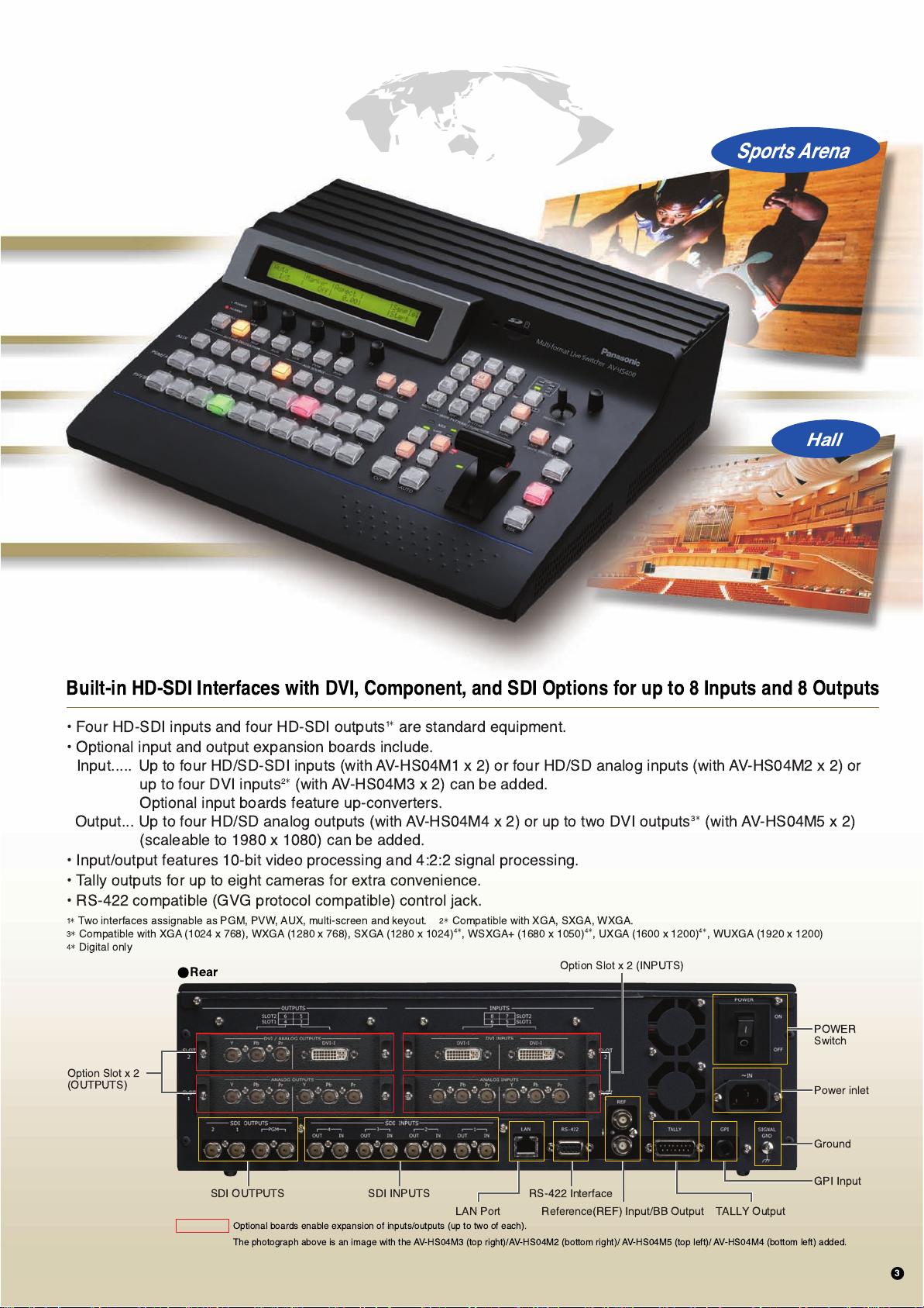
Built-in HD-SDI Interfaces with DVI, Component, and SDI Options for up to 8 Inputs and 8 Outputs
1
¥ Four HD-SDI inputs and four HD-SDI outputs
¥ Optional input and output expansion boards include.
Input..... Up to four HD/SD-SDI inputs (with AV-HS04M1 x 2) or four HD/SD analog inputs (with AV-HS04M2 x 2) or
2
up to four DVI inputs
*
(with AV-HS04M3 x 2) can be added.
Optional input boards feature up-converters.
Output... Up to four HD/SD analog outputs (with AV-HS04M4 x 2) or up to two DVI outputs
(scaleable to 1980 x 1080) can be added.
¥ Input/output features 10-bit video processing and 4:2:2 signal processing.
¥ Tally outputs for up to eight cameras for extra convenience.
¥ RS-422 compatible (GVG protocol compatible) control jack.
1
Two interfaces assignable as PGM, PVW, AUX, multi-screen and keyout.
*
3
Compatible with XGA (1024 x 768), WXGA (1280 x 768), SXGA (1280 x 1024)
*
4
Digital only
*
Rear
Option Slot x 2
(OUTPUTS)
*
are standard equipment.
2
Compatible with XGA, SXGA, WXGA.
*
4
*
, WSXGA+ (1680 x 1050)
4
*
, UXGA (1600 x 1200)
Option Slot x 2 (INPUTS)
3
*
(with AV-HS04M5 x 2)
4
*
, WUXGA (1920 x 1200)
POWER
Switch
Power inlet
SDI OUTPUTS
Optional boards enable expansion of inputs/outputs (up to two of each).
The photograph above is an image with the AV-HS04M3 (top right)/AV-HS04M2 (bottom right)/ AV-HS04M5 (top left)/ AV-HS04M4 (bottom left) added.
SDI INPUTS RS-422 Interface
Reference(REF) Input/BB Output TALLY OutputLAN Port
Ground
GPI Input
3
Page 4

Key Features
Multi-system compatibility f or extra flexibility
“Compact” –– with all the functions you need
The main unit and control panel are integrated in a compact body.
Cross-point Buttons for AUX Bus Only
Selects CLN, PVW and PGM material that is selectable
with the AUX bus only.
Rotary Encoder F1-F5
Sets parameters displayed
in the menu.
LCD
Displays settings menu.
POWER Indicator
ALARM Indicator
AUX BUS DELEGATION
Buttons
Switches AUX Bus
Crosspoint button application
between KEY, DSK and PinP
buses.
KEY/AUX Bus
Cross-point row
Select the source of the bus
switched with the KEY/AUX
Bus Cross-point row.
PGM/A Bus
Cross-point row
Select the PGM/A-Bus
video signal.
USER Assignable Buttons
Some functions from the menu can be
assigned to these two buttons.
SD Card Section
Still images recorded on an SD Card can be
used as background or key images.
SD Cards can also be used to store frame
memory images and settings data.
SD Card is not included.
*
WIPE PATTERN/FUNCTION
Selection Buttons
Pattern Page Indicator
Lights indicate wipe, squeeze, slide
or 3D.
Encoder for Adjustment(Z)
In conjunction with the positioner (X, Y),
used to set PinP and wipe location,
chroma key range and other parameters.
POSITIONER(X,Y)
WIPE PATTERN/FUNCTION
Mode Selection Buttons
Selects from background wipe,
KEY wipe or FUNCTION for
WIPE PATTERN/FUNCTION
Selection buttons.
WIPE DIRECTION Selection
Buttons
Independent Transition
Execution Buttons
Switches FTB (Fade-to-Black),
PinP and DSK ON/OFF.
KEY ON/OFF or disable can be
set in the FTB menu.
Fader Lever
PST/B Bus Cross-point row
Select the PST/B-Bus video signal.
Next Transition Selection Buttons
Select transition image from background and key.
Transition Type Selection Buttons
Selects the transition type option, selected with,
Next Transition selection buttons for background and KEY.
¥ MIX - Switches A-/B-bus images while overlapping.
¥ WIPE - Performs transition using the pattern selected with the Wipe Pattern Selection button.
4
MIX/WIPE Selection Status Indicator
Indicates background and
KEY transition type selection status.
Bus Tally Indicator
Indicates A-, B-Bus output status.
KEY ON Status Indicator
Transition Execution Buttons
¥ AUTO - Executes automatic transition at a set time.
¥ CUT - Executes instant transition.
Page 5

in the field and studio.
for superb results.
Multi-view display Preview on a
Single Monitor
Multi-view display lets you view PGM, PVW,
and inputs (up to 10) on a single screen,
reducing the number of monitors required.
Example of an AV-HS400 monitor system
Simultaneous split-screen preview
with a single monitor.
Number and Location of Images
is Selectable
¥ Display of signal name in each screen (ON/OFF possible).
¥ Display of red tally indications in frames for PGM output.
¥ Left/right switching of PGM and PVW screens possible.
¥ Arrangement of the images can be changed.
Example of conventional monitor system
Connection of separate monitors is required
for each input, PVW and PGM.
The image shows loop-through outputs connected to switcher inputs.
*
Ten Split Pictures (images)
Eight Split Pictures (images)
Four Split Pictures (images)
5
Page 6

Key Features
Multiple Effects for Stunning Results
In addition to standard wipe patterns, the DVE allows you to enjoy squeeze and slide effects,
and different types of 3D. Luminance key, chroma key and DSK are also provided as standard.
Plus PinP (Picture-in-Picture), with extremely simple operation.
A total of 43 effects offer great creative flexibility
WIPE SQ (Squeeze)
Switching between 12 wipe patterns. Switching between 11 types of squeeze including center, top and bottom.
SQ SQ
(images:pattern4)(images:pattern4)
SQ
123
456
789
10 11 12
SL SL
1
SL SL
456
SL SL SL
789
No Pattern No Pattern No Pattern
10 11
23
No Pattern
SL
12
1
SQ SQ SQ
456
SQ SQ SQ
789
SQ SQ
10 11 12
No Pattern
3D (3 Dimension)SL (Slide)
Switching between 3D effects such as page turn and rotate.Switching between up, down, left, right and diagonal slide effects.
123
456
789
10 11 12
23
(images:pattern1)(images:pattern4)
Chroma key for broadcast quality composite images Example of
High-quality chroma key for broadcast and commercial production applications.
Chroma key material Background material
6
After composition
composite effect
WIPE
PinP
DSK
(images)
Page 7

SYSTEM EXAMPLE
Ready for broadcast and
studio production
applications.
HD-SDI camera environment
(with Genlock)
=Option Boards
SDI INPUTS(AV-HS04M1)
SDI INPUTS(AV-HS04M1)
ANALOG OUTPUTS(AV-HS04M4)
Ideal for use with simple
systems at CATV stations,
schools and other locations.
HD camera environment
(no Genlock): Using the HD
Analog component option
=Option Boards
DVI INPUTS(AV-HS04M3)
ANALOG INPUTS(AV-HS04M2)
DVI/ANALOG OUTPUTS(AV-HS04M5)
Signal Generator
HD-SDI Camera
Inputs 5 to 8 can
*
also be upconverted
to SD-SDI.
HD VTR
(Spare Line)
HD VTR
(Main Line)
HD Analog
Camera
HD-SDI Camera
or
HD VTR P2 Mobile
PC
IN(REC)
OUT(Monitor)
IN(REC)
OUT(Monitor)
OUT(PLAY)
IN(REC)
DVI or VGA
B.B.
HD-SDI
HD-SDI
HD-SDI
HD-SDI
HD(SD)-SDI
HD(SD)-SDI
HD(SD)-SDI
HD(SD)-SDI
HD Analog Component
HD Analog Component
HD-SDI
HD-SDI
HD Analog
Component
AV-HS400
HD SDI (Ach)
HD SDI (Bch)
HD SDI (Ach)
HD SDI (Bch)
HD Analog Component
DVI
AV-HS400
HD-SDI
HD-SDI Monitor
HD-SDI Monitor
PC Monitor
HD-SDI Monitor
PDP
PDP
or
Projector
Provides the flexibility
required for facilities moving
from SD to HD production.
A combined HD/SD environment
without Genlock.
=Option Boards
ANALOG INPUTS(AV-HS04M2)
SDI INPUTS(AV-HS04M1)
DVI/ANALOG OUTPUTS(AV-HS04M5)
ANALOG OUTPUTS(AV-HS04M4)
Option Boards
You can expand inputs/outputs to match your system.
INPUTS
SDI INPUTS
AV-HS04M1
INPUTS: HD/SD-SDI x 2(BNC)(Built-in Up-converter)
Analog Material (Optional Input)
SD Analog
HD Analog
SD Material (Optional Input)
SD-SDI
HD-SDI
SD Material (Standard Input)
SD-SDI
HD-SDI
ANALOG INPUTS
AV-HS04M2
INPUTS: HD/SD ANALOG Component x 2(Y/Pb/Pr)
(Built-in Up-converter)
SD Use HD Use
Up-Converter
Up-Converter
Analog Component
SDI
SDI
Analog Component
HD/SD Analog Component
DVI
AV-HS400
SDI
HD/SD-SDI Monitor
OUTPUTS
ANALOG OUTPUTS
AV-HS04M4
OUTPUTS: Analog Component x 2(Y/Pb/Pr)
Monitor
PC Monitor
DVI INPUTS
AV-HS04M3
INPUTS: DVI-I x 2(Built-in Scaler)
DVI/ANALOG OUTPUTS
AV-HS04M5
OUTPUTS: DVI-I x 1, Analog x 1
7
Page 8

Specifications
Video processing
M/E
Input
Output
Dimensions
Video format
Video processing
Video
Key
DSK
Reference
Video
Reference
SD (480/59.94i, 576/50i),
HD (1080/59.94i, 1080/50i, 720/59.94p, 720/50p)
1M/E
Y:Cb:Cr, 4:2:2 10 bit
RGB, 4:4:4 8 bit
4 inputs (HD/SD-SDI)
Option: A maximum of four inputs (up to 2 boards each of 2 of
3 types of input boards can be added: HD/SD-SDI x 2,
HD/SD-analog x 2, DVI/RGB x 2).
Assign one out of video inputs
Assign one out of video inputs
Black burst/TRI (loop through) x 1
Standard: Four outputs (PGM x 2, general-purpose x 2,
each HD/SD-SDI )
Option: A maximum of four outputs (up to 2 boards each of
2 types of output boards can be added: general-purpose x 4, each
HD/SD-analog x 2, DVI/analog x 1 each).
The six general-purpose output interfaces (OUT1 to 6) above are
assignable as PGM, PVW, AUX, multi-screen and keyout.
Loop through x 1 (Genlock),
Black burst x 1 (internal synchronization)
WIPE x 12, Squeeze x 11, SLIDE x 8, 3D DVE x 12 (3 directions)
WIPE/DVE
Transition
KEYER
PinP
Interface
Removable media
Power
Dimensions (W x H x D)
Features and specifications in this document are subject to change without notice due to continual improvements.
*
Pattern
Transition method
Transition type
Key source
Key fill
Key mode
Transition method
Transition type
Serial (EDITOR)
Tally output
GPI
Ethernet
SD memory card slot
Excluding 3D, selection with key transition is possible independently
of background.
FADER, AUTO
Cut, mix, wipe (including DVE), background and
key can be selected.
BUS
BUS, MATTE
Linear key, Lum key, Chroma key (Key only)
AUTO (PinP only)
MIX
Dsub9pin x 1: RS422A (GVG protocol compatible)
Dsub15pin x 1, open collector output
¿ 3.5 Stereo mini jack
100 Mbps/10 Mbps x 1 (Service purpose)
1 (for transferring still image files and providing an upgrade capability)
AC 220 V to 240 V, 50 Hz/60 Hz
420 mm x 132 mm x 408 mm (excluding protrusions)
420 mm
132 mm
22 mm
408 mm
SD Logo is a trademark.
AV-JECHS40007
Printed in Japan
 Loading...