

Page 1
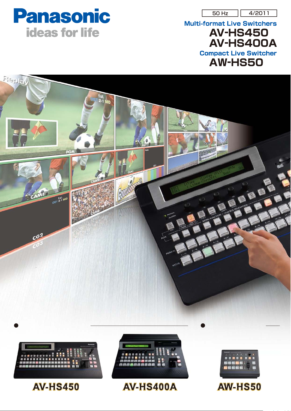
HD live production
better than ever.
Multi-format Live Switchers Compact Live Switcher
Page 2
Advanced broadcast quality HD technology in a compact size.
A global line-up suitable for a myriad of applications.
Memory Card
Camera-Recorder
10 80/59.9 4i ,50i,
H D
72 0/59.94 p, 50p
48 0/59.94 i, 576/5 0i
S D
Multi-purpose Camera
AK-HC1800
AK-HC1500
HD Convertible Camera
AW-HE870
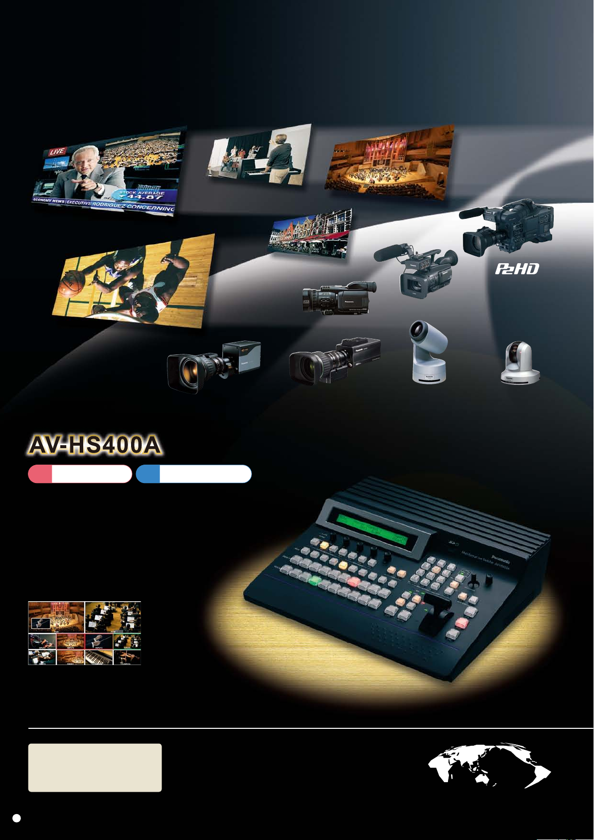
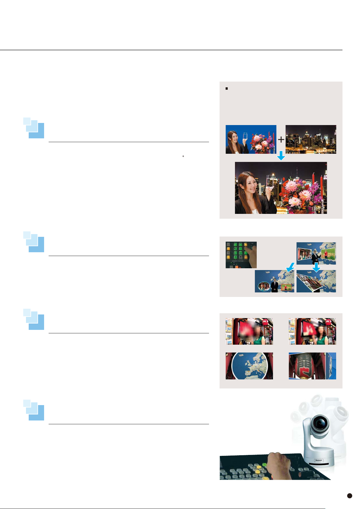
An all-in-one, 1ME switcher supplied with a MultiViewer,
dual 3D-DVE, AUX Bus, and much more.
The HS400A is equipped with four HD/SD-SDI inputs and three outputs,
and expandable to eight-in and seven-out.
Standard equipment includes PinP (Picture in Picture),
Chroma Keyer and DSK (Downstream Keyer), Frame Sync,
PTZ camera control, SD Card,
and Ethernet Graphics Transfer.
10 Split Pictures
HD/SD Integrated Camera P/T
AW-HE100
HD Integrated Camera
AW-HE50S
Multi-format
HD/SD compatibility
for worldwide use
2
Compatibility with various HD/SD formats will help you meet
changing production needs as video production shifts towards
HD on a global scale. You can also use optional cards to combine
a variety of HD and SD signals in a flexible system,
as you make a smooth transition from SD to HD.
Page 3
10 80/59.9 4i ,50i, 24 PsF*,2 3.98PsF*,
H D
72 0/59.94 p, 50p
AV-HS04M1, M2, M3, M4, M5, M6, M7, M7D, and M8 cards do not support 24PsF or 23.98PsF.
*
48 0/59.94 i, 576/5 0i
S D
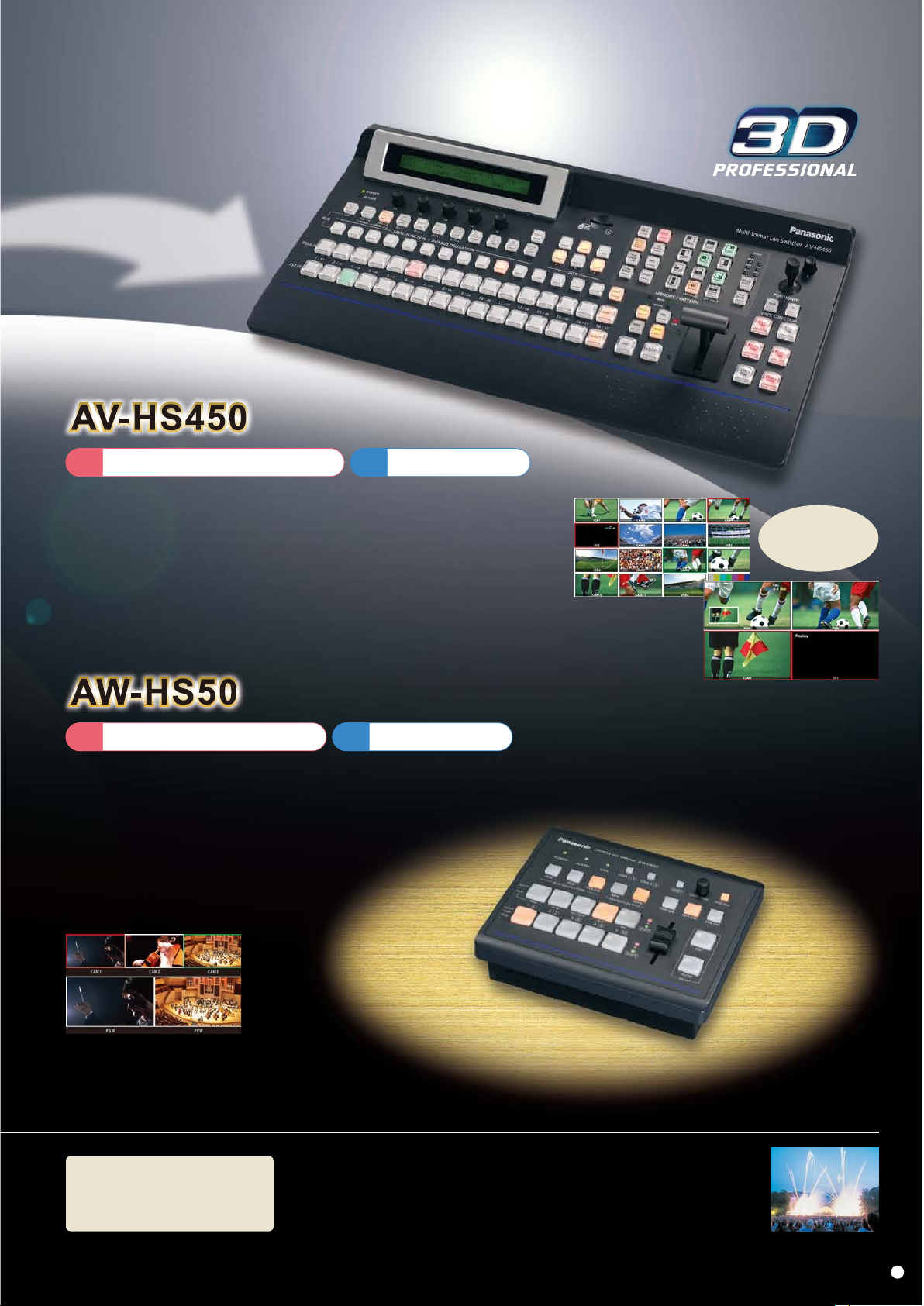
HD switcher with 16 SDI inputs, 4 SDI outputs, 2 DVI outputs,
and Dual-screen MultiViewer as standard equipment.
Expandable to 20 inputs or 10 outputs, this powerful 2-piece switcher includes a wide range of
standard functions, including dual PinP, dual DSK, dual channel 3D DVE, four AUX busses,
shot and PinP memories, a powerful chroma keyer, PTZ camera control with preset memories,
dual redundant power supplies and much more.
16 Split Pictures
4 Split Pictures
Can simultaneously
display up to
20 windows on
two screens.
10 80/59.9 4i ,50i, 24 PsF,2 3. 98PsF,
H D
72 0/59.94 p, 50p
48 0/59.94 i, 576/5 0i
S D
Compact, yet multi-functional.
Comes with a MultiViewer display function for professional HD production.
A digital video switcher equipped with 4 SDI inputs, 1 DVI-D input,
2 SDI outputs and 1 DVI-D output.
Despite its compact half rack size, the switcher provides professional
HD production with its built-in MultiViewer display function,
which lets you select from 8 split-screen patterns,
and frame synchronizer.
5b Split Pictures
Built-in
Frame Synchronizers
suitable for field operation
Each input features a built-in high-performance 10-bit Frame Synchronizer.
You can also smoothly switch asynchronous video signals without
experiencing shock or freeze. It is also compatible with the reference (black burst)
signal input, so you can synchronize with external systems (excludes AW-HS50).
3
Page 4
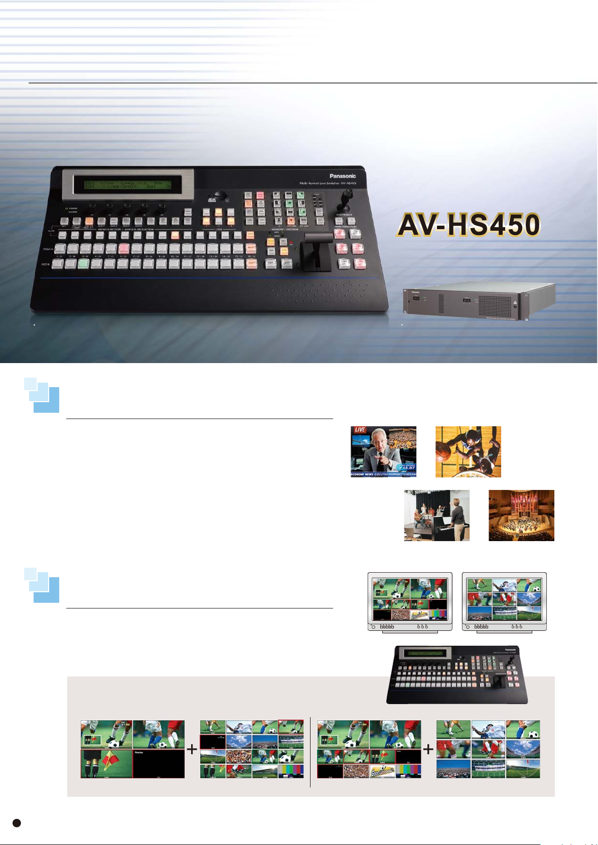
Versatile inputs/outputs and dual-screen Multi Viewer for powerful, cost effective production.
Multi-format Live Switcher
Control panel Mainframe
Built-in 4 up-converters and 8 color correctors.
Also comes with redundant power supply.
The compact 2RU mainframe size switcher is standardly equipped with 16
HD/SD-SDI input channels. All inputs feature a built-in Frame Synchronizer.
It is also mounted with 4 up-converters and 8 color correctors. Its standard
output configuration includes 4 HD/SD-SDI output channels and 2 DVI-D
output channels. In addition, it features 4 Aux busses*
with a MIX transition function. In combination with mix effects, the switcher
enables a flexible production workflow, and the redundant power supply
ensures smooth field operation.
1 Embedded audio on SDI input signals can be passed through PGM, PVM, and MV.
*
1
, and the Aux 1 comes
Built-in dual-monitor multi display function
with up to 20 windows.
Standardly equipped with a dual-monitor multi display function. A maximum
of 20 channels including program (PGM), preview (PVW), and input video
signal can be simultaneously displayed on 2 screens. The exclusive feature
lets you work comfortably with only two monitors, even at large-scale events.
An extensive range of inputs and outputs will help you
build a versatile system.
Excellent performance in various situations from
broadcasting, entertainment, to education.
News Magazine Show
Education
Sports Arena
Halls / Theaters
4, 9, 10 and 16 split-screens can be selected.
Audio level meters (group 1/ 1 ch, 2 ch) can be displayed on each split screen.
A maximum of 20 channels may be simultaneously displayed on 2 screens.
4 Split Pictures 16 Split Pictures 10 Split Pictures 9 Split Pictures
4
Page 5
Standard configuration includes dedicated
hardware for 2 DSK and 2 PinP channels.
The built-in upstream keyer includes luminance and chroma key functions.
The HS450 chroma keyer employs the powerful Primatte algorithm,
previously only available for use with high-end non-linear editing systems.
Widely used in motion picture and TV production, incorporation of Primatte's
algorithm into the HS450 now provides easy to adjust, high-precision
compositing technology for live production. In addition, the switcher comes
equipped with dedicated hardware for 2 DSK and 2 independent channels of
picture-in-picture.
●
●
●
®
Primatte
The copyrights of Primatte
The patents for Primatte
is a registered trademark of IMAGICA DIGIX Inc.
®
®
belong to IMAGICA DIGIX Inc.
belong to IMAGICA DIGIX Inc.
Embedded with high-grade
chroma key technology
By matching transparent materials such as silk and glass to
the background color, the superb spill removal function
produces natural, realistic results.
Reproduces details of elaborate content such as hair with
great precision.
Enhanced shot memory and PinP memory
for streamlined operation.
You can store up 10 memorized image states for background transition
pattern, PinP size, position and border width. The switcher is also equipped
with an effect dissolve function*
2
. These enhanced memory functions enable
a smoother and more intuitive production workflow.
2 You can smoothly switch from the current image to the image or
*
operation store in the SHOT memory.
A wide range of 2D and 3D effects
enhance creative expression.
In addition to standard wipe, mix, and cut transitions, powerful 2D and 3D
DVE effects such as squeeze, slide, rotation, and page turn are now available.
Dual channel DVE effects are also available for dramatic key effects and
other creative transitions. Useful new effects include variable mosaic and
selectable defocus.
Superior PTZ camera system control
with preset recall and save functions.
You can call up
the stored images
and effects by
pressing the select
button.
Mozaic Deforcus
Ellipse wipe 2 channel 3D
The HS450 offers advanced control of Panasonic pan-tilt camera systems*3,
including the AW-HE100 HD integrated PTZ camera. You can control one
camera via direct serial connection, or up to 5 in conjunction with system
controllers*
4
. Up to 10 preset positions may be stored or recalled for each
camera.
3 Compatible models: AW-PH400/AW-PH405/AW-PH360.
*
4 Compatible models: AW-RP655/AW-RP555.
*
Control camera and pan-tilt systems right
from the switcher to easily capture
perfectly framed video.
5
Page 6
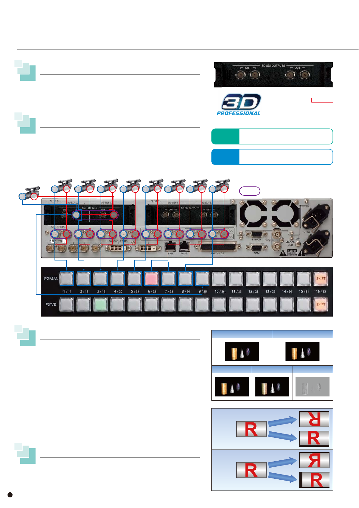
Using the AV-HS04M7D Option Board Enables 3D Video Production on the AV-HS450.
2D/3D Switchable 3D SDI Output Board
When the AV-HS04M7D and V2.0 Software are installed in the AV-HS450,
CAM9
L R
they enable the switcher to process 3D, stereoscopic video. The AV-HS04M7D
also can function as a normal HD output board and, through use of its built-in
downconverters, can provide SD output as well.
Up to nine pairs of inputs in 3D
In 3D mode, up to nine stereoscopic cameras and other sources can be employed.
Two Channel, simultaneous video cuts, dissolves, wipes and other transitions
are easily performed for use in 3D production of sports, live entertainment,
and other immersive content.
●
Setting the Crosspoints
CAM1
L R
CAM2
17 18
CAM3
CAM4
CAM5
CAM6
CAM7
Compatible formats for AV-HS04M7D
2D MODE
3D MODE
CAM8
1080/59.94i, 1080/50i, 720/59.94p, 720/50p,
480/59.94i, 576/50i
1080/59.94i, 1080/50i, 720/59.94p, 720/50p
3D SDI Output Board
AV-HS04M7D
OUTPUTS : HD/SD-SDI x2
(Each one has 2 outputs) (BNC)
(Built-in Down-converter)
Option Boards: AV-HS04M1
:Pair (combination cannot be changed)
NEW
for AV-HS450
AV-HS04M7D
1 2
L RL R
3 4
5 6
7 8
9 10
11 12
Mixed Outputs Facilitate 3D Adjustments
●
LRMIXa (LR mix a):
The L ch and R ch images are mixed, and the mixed images are output on a
single channel for quick checking of convergence on a 2D monitor.
●
LRMIXb (LR mix b):
Magenta is mixed within the L ch LRMIXa image and green is mixed
within the R ch LRMIXa image, and the images are output for rapid assessment
of plus and minus convergence.
●
LRDiff (LR difference display):
The luminance components of the L ch and R ch images are compared, and
the difference between them is displayed using a gray scale. Using the R ch
image as the reference, the parts of the L ch image with a higher luminance
are displayed brightly while the parts of the same image with a lower
luminance are displayed dimly. Parts where the luminance of the L ch and
R ch images is identical are displayed using 50 % gray.
13 14
15 16
L ch image R ch image
LRMIXa LRMIXb LRDiff
Mirror
Vertical reversal/Positioning
3D correction function
Mirror
Vertical/horizontal reversing and position correction are possible for all 16
channels of SDI standard inputs. Position correction does does include blanking
correction, and so is not intended for program distribution.
Horizontal reversal/Positioning
6
Page 7

Ten Split Pictures (LRMIXa Image)
Stereoscopic 3D chroma key compositing
Extraordinary 3D stereoscopic chroma keying can be achieved onsite, in real
time, using the embedded multi-layer Primatte
●
●
●
®
Primatte
The copyrights of Primatte
The patents for Primatte
is a registered trademark of IMAGICA DIGIX Inc.
®
®
belong to IMAGICA DIGIX Inc.
belong to IMAGICA DIGIX Inc.
3D video signal status monitor displays
The 3D video and 3D video signal status monitor can be displayed together in PGM output and PVW output of the multi-view display
(1/4 size only), enabling smoother 3D switching while checking the “protrusion” and “depth” differences between PGM and PVW.
Additionally, this screen can be fed back to the camera side, and adjustments such as the brightness and horizontal/vertical positioning
correction can be easily applied. These functions may be particularly useful when used to provide visual feedback to camera and rig operators.
●
Distribution of Lch and Rch signal components
Lum, Red, Green, Blue Prllx
Distribution
Signal component level
(luminance, R, G and B)
amounts of levels
HigherLower
Jutting out
direction
●
Approx.
-7.5 %
Distribution of
®
compositing firmware.
Distribution of amount of parallax in 3D images
Amount of parallax
amount of parallax
Approx.
-3 % 0 %
Approx.
+3 %
Approx.
+7.5 %
Recessed
direction
L
R
L
L
R
●
A grid is displayed at intervals of about 3 % along
the width of the screen.
Grid
R
R
Higher Lower
Green display area:
Indicates a distribution with many L ch components.
Red display area:
Indicates a distribution with many R ch components.
●
AV-HS450 manufactured before February 2011 requires a software version upgrade to use AV-HS04M7D. Contact a local sales outlet for details. ●AV-HS04M7D can only be
Higher Lower
Histogram of amount of parallax (L ch and R ch)
Bar used for input signal (L ch and R ch) compensation
Select LRMIXa or LRMIXb as the 3D output format,
and shoot so that the amount of parallax between Lch
and Rch come within the grid width.
mounted to AV-HS450 slot B. It will not operate even in 2D mode if mounted to slot A. ●AV-HS04M7D is not compatible with AV-HS400/HS400A.
7
Page 8

A compact, high-performance, global standard model compatible with multi-view display.
Multi-format Live Switcher
A compact switcher equipped with
every function needed for great video production.
The control panel, switching circuitry, connection panel, and MultiViewer are
integrated into a single compact unit, providing great portability and ease of
use. The HS400A comes equipped with all the features required for high-level
video production, and a simple, streamlined control panel layout makes
creative switching a breeze.
The Built-in MultiViewer Can Reduce System Cost,
Save Space, and Streamline Production Workflow.
Reduce the number of monitors and build an environmentally conscious system by dividing the
screen to display numerous sources on a single monitor. You can edit the label of source windows,
turn the labels on or off, adjust label brightness, and turn off the label background bar. You can also
adjust the frame line brightness, or turn the frame lines off for use as a multi-image program display.
Selectable Split-screen Quantity and Location
• The window layout can be selected: 4, 8, or 10.
• Red/Green Program/Preview tally indicators may be displayed
• Split-screen labels may customized or selected from menus.
1
• When splitting screens into 10/8 sections, the upper 2 windows
*
.
may be selected from PGM/PVW/AUX BUS/KEYOUT images.
10 Split Pictures 8 Split Pictures 4 Split Pictures
1 The tally output connector is not compatible to green tally output.
*
8
Page 9

Basic HD/SD configuration includes 4 SDI inputs and
2
*
3 assignable SDI output channels
.
Using optional I/O boards, the HS400A can be expanded
to a maximum of 8 input and 7 output channels.
The HS400A may be easily expanded to suit a wide range of applications through the use of
optional input and output boards. Tally connections for up to 8 cameras are included as
standard equipment, as is an RS-422 control port compatible with the basic GVG protocol.
• Optional input and output boards include:
I n p u t s : AV-HS04M1: Dual HD/SD-SDI with Up-conversion
AV-HS04M2: Dual HD/SD Analog Component with Up-conversion
AV-HS04M3: Dual Scalable DVI
AV-HS04M6: Dual SD Analog Composite with Up-conversion
AV-HS04M8: Dual DVI-D
3
compatible with WUXGA
*
Outputs: AV-HS04M4: Dual HD Analog Component
AV-HS04M5: Scalable DVI and HD Analog Component
AV-HS04M7: Dual HD/SD-SDI with Down-conversion
2 Two interfaces assignable as PGM,PVW, AUX, multi-screen, and keyout.
*
3 AV-HS400, and AV-HS400A manufactured before January 2010 require version upgrades.
*
Please contact a local sales outlet for details.
Comes with a great diversity of effects to expand
your creative expression.
The wide range of input and
output configurations are ideal
for many applications.
Education
Studio Use
Halls / Theaters
In addition to standard wipe patterns, you can employ slide, size-reduction, and a variety
of 3D effects. 3D transitions can also be applied independently to the upstream key
function, for dramatic graphic and titling effects to luminance and chroma keys. PinP and
DSK functions are also included as standard equipment.
WIPE (images: pattern4)
3D (images: pattern1)
PinP
Example of a
compound effect
WIPE
Remotely control the AW-HE100 and other Panasonic pan-tilt systems*4.
Directly connecting the AW-HE100 3CCD integrated pan/tilt/zoom camera or a Panasonic camera/pan-tilt system*4 allows control
over pan, tilt, zoom, and focus using the HS400A's positioner.
Moreover, by also connecting a Panasonic control panel*
4 Compatible models: AW-PH400/AW-PH405/AW-PH360. *5 Compatible models: AW-RP655/AW-RP555.
*
Direct connections
HD/SD Integrated Camera P/T
AW-HE100
RS-422
Video Signal
Monitor
5
you can switch between and operate up to 5 cameras and pan-tilt heads*4.
Multiple camera connections
HD/SD Integrated Camera P/T
AW-HE100
Video SignalRS-422
Multi-format Live Switcher
AV-HS400A
You can upgrade the existing AV-HS400. Please contact Panasonic for more information.
RS-422/232C
Pan-tilt Control Panel
AW-RP555/AW-RP655
Converter
RS-422
Multi-format Live Switcher
AV-HS400A
Monitor
9
Page 10

AV-HS450 Controls and Functions
Co nt ro l pa ne l
5 13
12
SD Memory Card is not included.
*
Image file transfer via LAN
Compatible with JPEG/TIFF/PNG/GIF/BMP.
Software supplied with switcher.
*
*
1
2
3
4
6
7
9
10
11
20
21
Ma in fr am e Re ar
Cooling fan
Optional input/output slot SLOT A Optional input/output slot SLOT B
24
23
EDITOR Port
Reference input connector/BB output connector
14
15
16
19
18
17
27
28
26
25
22
SDI signal input connectors
• IN9 to IN16 : Color corrector
• IN13 to IN16 : Up-converter
SDI signal
output connectors
Up to two optional boards can be added via input/output slots.
LCD
1
Displays settings menus.
Power indicator
2
Alarm indicator
3
Rotary encoders [F1] to [F5]
4
Sets parameters displayed in the menu.
[HOLD] button (only applies to AV-HS450)
5
Prohibits switching to Menu and AUX bus select buttons.
Menu function buttons
6
For direct selection of many menu functions.
AUX bus selector buttons
7
Switches AUX Bus Crosspoint button application between KEY, DSK and PinP buses.
AUX bus dedicated crosspoint buttons (only applies to AV-HS400A)
8
Selects CLN, PVW and PGM material that is selectable with the AUX bus only.
AUX bus crosspoint buttons
9
Select the source of the bus switched with the KEY/AUX Bus Cross-point row.
DVI-D
output connectors
LAN Port
TALLY/GPI
input/output connector
PANEL Port
PGM/A bus crosspoint buttons
10
Select the PGM/A-Bus video signal.
PST/B bus crosspoint buttons
11
Select the PST/B-Bus video signal.
SD memory card slot
12
Still images (JPEG, BMP) recorded on an SD Memory Card can be used as
background or key images. SD Memory Cards can also be used to
store frame memory images and settings data.
• The AV-HS450 is compatible with SD/SDHC Memory Cards.
• The AV-HS400A is compatible with SD Memory Cards.
SDHC/SD logos are registered trademarks.
User buttons
13
You can assign various menu functions to these button for one-touch access.
Memory operation buttons (only applies to AV-HS450)
14
Wipe pattern selector buttons
15
• With the AV-HS450, data can be stored in the memories of buttons 1 to 10 or
recalled from these memories while one of the memory operation buttons.
COM Port
Ground connector
AC power input sockets
10
Page 11

AV-HS400A Controls and Functions
13
8
1
12
SD Memory Card
*
is not included.
Image file transfer via LAN
Compatible with JPEG/TIFF/PNG/
GIF/BMP.
Software supplied
*
with switcher.
*
2
3
4
7
9
10
11
Option output slot [SLOT2]
Option output slot [SLOT1]
Re ar
20
21
Option input slot [SLOT2] Cooling fanOption input slot [SLOT1]
6 / 15
16
19
18
17
27
28
26
25
22
23
24
Power switch
AC power input socket
Ground connector
SDI signal
output connectors
You can add up to two optional input cards and two optional output cards via the dedicated slots.
Pattern page indicator LEDs
16
Indicates the status of the pattern page selection such as "WIPE (wipe) /
SQ1 (squeeze 1) / SL1 (slide 1) / 3D1 (3 dimension 1) / SQ2 (squeeze 2) /
SL2 (slide 2) / 3D2 (3 dimension 2)" for AV-HS450 and "WIPE (wipe) /
SQ (squeeze) / SL (slide) / 3D (3 dimension)" for AV-HS400A.
BKGD,KEY pattern selector buttons
17
Selects from background wipe, KEY wipe or
FUNCTION (only applies for AV-HS400A) for
WIPE PATTERN/FUNCTION Selection buttons.
Positioner [X/Y]
18
Rotary encoder [Z]
19
In conjunction with the positioner (X, Y), used to set PinP and
wipe location, chroma key range and other parameters.
MIX, WIPE selection status tally LEDs
20
Indicates background and KEY transition type selection status.
Next transition selection buttons
21
Select transition image from background and key.
SDI signal
input connectors
LAN Port
RS-422 interface connector
22
23
24
25
26
27
28
Reference input connector/
BB output connector
KEY ON tally LED
Transition type selection buttons
Selects the transition type option, selected with, Next Transition selection buttons
for background and KEY.
• MIX - Switches A-/B-bus images while overlapping.
• WIPE - Performs transition using the pattern selected with the Wipe Pattern Selection button.
Transition execution buttons
• AUTO - Executes automatic transition of a selected duration.
• CUT - Executes instant transition.
Bus tally LEDs
Indicates A-, B-Bus output status.
Fader lever
Wipe direction selection buttons
Transition execution buttons
Switches FTB (Fade-to-Black), PinP and DSK ON/OFF.
With the AV-HS400A, you can disable or change the FTB to KEY ON/OFF.
GPI input connector
TALLY output connector
11
Page 12

AV-HS450 System Diagrams
AV-HS450
Adding the optional board
AV-HS04M7D ensures
professional 3D production.
This example employs
HD-SDI camera environment
without Genlock.
=Option Boards
3D SDI OUTPUTS (AV-HS04M7D)
HD-SDI Camera
AK-HC1800
Integrated Twin-lens
3D Camera Recorder
AG-3DA1
3DRig Camera
AK-HC1800 x 2
Integrated Twin-lens
3D Camera Recorder
AG-3DA1
HD-SDI 2D
HD-SDI R ch
HD-SDI L ch
HD-SDI R ch
HD-SDI L ch
HD-SDI R ch
HD-SDI L ch
HD-SDI L ch
HD-SDI R ch
HD-SDI L ch
HD-SDI R ch
Projector
3D LCD Video Monitor
BT-3DL2550
Ideal for use at broadcast
stations, production
companies, as well as in
mid-sized studios and
production vans.
This example employs
HD/SD-SDI cards for all cameras
and uses an external sync
generator for Genlock reference.
Memory Card
Portable Recorde
AG-HMR10
Memory Card
Portable Recorde
AG-HMR10
Sync signal generator
(Sync Generator)
HD VTR
HD Video
Player
HD-SDI Cameras
AK-HC3500
AK-HC1800
AK-HC1500
HD-SDI Monitor
PC Monitor
AW-HE870
AW-HE100
HD-SDI L ch
HD-SDI R ch
HD-SDI L/ R ch HD-SDI L/ R ch
3D LCD Video Monitor
BT-3DL2550
B.B.
HD-SDI
HD-SDI
HD-SDI
HD-SDI
HD-SDI
HD-SDI
HD-SDI
HD-SDI
HD-SDI
HD-SDI
DVI
DVI
HD-SDI
HD-SDI
HD-SDI
HD-SDI
SD-SDI
SD-SDI
SD-SDI
SD-SDI
LAN cable
Mainframe
LAN cable
3D LCD Video Monitor
BT-3DL2550
Mainframe
B.B.signal (D.A. required)
Control panel
FILL
KEY
FILL
KEY
outdoor pan-tilt system AW-PH650.
PC
Weather camera,
SD camera +
SD VTR
Control panel
12
Page 13

AV-HS400A System Diagrams
AV-HS400A
Ready for broadcast and
studio production
applications.
This example employs
HD-SDI camera environment
with Genlock.
=Option Boards
SDI INPUTS (AV-HS04M1)
SDI INPUTS (AV-HS04M1)
ANALOG OUTPUTS (AV-HS04M4)
Ideal for use with smaller
systems at cable stations,
schools, churches,
and for mobile flypacks.
This example employs HD Analog
and other option cards,
and does not require Genlock.
=Option Boards
DVI INPUTS (AV-HS04M3)
ANALOG INPUTS (AV-HS04M2)
DVI/ANALOG OUTPUTS (AV-HS04M5)
Sync signal generator
(Sync Generator)
Multi-format
Camera
AK-HC3500
Multi-purpose
Camera
AK-HC1500
AK-HC1800
Inputs 5 to 8 can also be
*
upconverted to SD-SDI.
HD VTR
(Spare Line)
HD VTR
(Main Line)
HD/SD Integrated
Camera P/T
AW-HE100
Multi-purpose
Camera
AK-HC1500
AK-HC1800
HD VTR
or
P2 Mobile
PC
IN(REC)
OUT(Monitor)
IN(REC)
OUT(Monitor)
OUT(PLAY)
IN(REC)
DVI or VGA
B.B.
HD-SDI
HD-SDI
HD-SDI
HD-SDI
HD(SD)-SDI
HD(SD)-SDI
HD(SD)-SDI
HD(SD)-SDI
HD Analog Component
HD Analog Component
HD-SDI
HD-SDI
HD-SDI
HD Analog
Component
AV-HS400A
HD-SDI (Ach)
HD-SDI (Bch)
HD-SDI (Ach)
HD-SDI (Bch)
B.B.signal (D.A. required)
HD Analog Component
DVI
AV-HS400A
HD-SDI
HD-SDI Monitor
HD-SDI Monitor
PC Monitor
HD-SDI Monitor
PDP
PDP
or
Projector
Provides the flexibility
required for facilities moving
from SD to HD production.
1. A combined HD/SD-SDI and
HD/SD analog component
environment without Genlock.
=Option Boards
ANALOG INPUTS(AV-HS04M2)
SDI INPUTS(AV-HS04M1)
DVI/ANALOG OUTPUTS(AV-HS04M5)
ANALOG OUTPUTS(AV-HS04M4)
2. A combined HD/SD-SDI and
analog composite environment
without Genlock.
=Option Boards
ANALOG COMPOSITE INPUTS
(AV-HS04M6)
SDI OUTPUTS (AV-HS04M7)
Analog Material (Optional Input)
SD Analog
HD Analog
SDI Material (Optional Input)
SD-SDI
HD-SDI
SDI Material (Standard Input)
SD-SDI
HD-SDI
Multi-purpose
Camera
AK-HC1500
AK-HC1800
Convertible Camera
AW-E350/E650/E750/E860
SD VTR
SD Use HD Use
Up-Converter
Up-Converter
Analog Component
HD/SD-SDI
HD/SD-SDI
HD-SDI
HD-SDI
SD Analog Composite
SD Analog Composite
Analog Component
DVI
AV-HS400A
HD/SD-SDI
AV-HS400A
HD-SDI
SD-SDI
SD-SDI
HD/SD Analog Component
Monitor
PC Monitor
HD/SD-SDI Monitor
HD-SDI Monitor
SD VTR
SD-SDI Monitor
13
Page 14

AV-HS450 / AV-HS400A Option Boards
Input/output formats compatible with the AV-HS450/AV-HS400A
AV-HS450 AV-HS400A
1
x2
*
M7D
SDI
x2
OUT IN
3
*
3
*
DVI-D
x2
Analog
composite
Analog
component
SDI
DVI analog
DVI digital
(PC)
DVI digital
(VIDEO)
Compatible
NTSC
PAL
480/59.94i
576/50i
1080/59.94i
1080/50i
720/59.94p
720/50p
480/59.94i
576/50i
1080/59.94i
1080/50i
720/59.94p
720/50p
1080/24PsF
1080/23.98PsF
XGA (1024 x 768)
WXGA (1280 x 768)
SXGA (1280 x 1024)
XGA (1024 x 768)
WXGA (1280 x 768)
SXGA (1280 x 1024)
UXGA (1600 x 1200)
WSXGA+ (1680 x 1050)
WUXGA (1920 x 1200)
1080/59.94p
1080/50p
Standard Standard Standard
SDI
SDIx4DVI-Dx2SDIx2COMPx2DVI-Ix2COMPx2DVI-I/
x16
M1 M2 M3 M4 M5 M6 M7 M8
COMP
IN OUT OUT IN IN IN OUT OUT IN OUT
60Hz
60Hz
60Hz
60Hz
60Hz
60Hz
60Hz
60Hz
60Hz
COMPSITx2SDI
1
StandardStandard
M1 M2 M3 M4 M5 M6 M7
SDIx4SDx3SDIx2COMPx2DVI-Ix2COMPx2DVI-I/
*
COMP
COMPSITx2SDI
IN OUT IN IN IN OUT OUT IN OUT
2
*
M8
DVI-D
x2
x2
IN
Option Boards You can expand inputs/outputs to match your requirements.
You can add up to 2 boards to the input/output option board slots of the AV-HS450, and up to 2 input and 2 output boards to the option board
slots of the AV-HS400A.
INPUTS
SDI Input Board
AV-HS04M1
INPUTS : HD/SD-SDI x 2 (BNC) (Built-in Up-converter)
OUTPUTS
2
*
Analog Component Input Board
AV-HS04M2
INPUTS : HD/SD Analog Component x 2 (Y/Pb/Pr)
(Built-in Up-converter)
Analog Composite Input Board
AV-HS04M6
INPUTS : Analog Composite x 2
(Built-in Up-converter)
Analog Output Board
AV-HS04M4
OUTPUTS : HD/SD
Analog Component x 2 (Y/Pb/Pr)
SDI Output Board
AV-HS04M7
OUTPUTS : HD/SD-SDI x 2
(Each one has 2 outputs) (BNC)
(Built-in Down-converter)
4
*
4
*
DVI Input Board
AV-HS04M3
INPUTS : DVI-I x 2 (Built-in Scaler)
Full HD DVI input board
AV-HS04M8
INPUTS : DVI-D x 2
(compatible with WUXGA)
DVI/Analog Output Board
AV-HS04M5
OUTPUTS : DVI-I x 1,
Analog Component x1 (Y/Pb/Pr)
3D SDI Output Board
AV-HS04M7D
OUTPUTS : HD/SD-SDI x 2
(Each one has 2 outputs) (BNC)
(Built-in Down-converter)
2
*
1
*
NEW
for AV-HS450
14
Page 15

AV-HS450 / AV-HS400A Option Boards
(specifications are based on AV-HS04M7D.)
AV-HS450 specifications when using AV-HS04M7D
Item 2D MODE
Frame Synchronizer, Freeze
INPUT
IN 1 to 16
+
[
OUT 1 to 4
[
OUT A1 to B2
●
2D and 3D modes are switchable in the menu. 2D and 3D modes cannot be used si multaneously. Internal settings are reset when switching between 2D and 3D modes.
●
3D-compliant monitors are required for the monitoring in 3D.
IN A1, A2
SDI OUT
+
DVI OUT
OUT 5, 6
+
[
OUT A2
BKGD
KEY
PinP
DSK
CBAR
LRmark
FMEM
MV
AUX
]
]
]
2D camera mode (IN 1-15, [A1])
Input signal reversing function
Input signal position correction function
MODE
MODE
Trans
Trans
Mode
Shape
Function
Number of CH
Up-converter (
Color collector (
Color correction data copy
(
horizontal/vertical
(
horizontal/vertical
Lum, Linear, Chroma, Full
IN 13 to 16
IN 9 to 16
)
)
Number of CH
L, R
MIX
Side-by-Side
Line-by-Line
Number of CH
L, R
MIX
Side-by-Side
Line-by-Line
CUT
MIX
WIPE
DVE
IMAGE A, B
BORDER
Number of CH
CUT
MIX
WIPE
DVE
EDGE
MASK
FlyKEY
Number of CH
PinP
Assign INPUT
Square (PinP1
Square (PinP2
Circle (PinP1
Circle (PinP2
Number of CH
Lum, Linear
EDGE
MASK
Number of CH
Number of CH
Number of CH
Number of CH
Number of CH
16 [18] ch
)
)
-
-
-
6 [8] ch
-
-
-
-
2 [3] ch
-
-
-
-
1 ch
2 ch
-
)
)
)
)
-
2 ch
1 ch
-
4 ch
2 ch
4 ch
3D MODE
(
L, R) × 8 [9] ch
5
*
5
*
6 [8] ch
6
*
2 [3] ch
7
*
8
*
-
-
(
L, R) x 1 ch
(
L, R) x 1 ch
-
-
-
(
L, R) x 2 ch
-
1 ch
(L,R) x1ch
4 ch
(L, R) x 1 ch
(L, R) x 4 ch
[ ]
is when the optional board AV-HS04M1 was used.
L, R Common Setting
L, R Common Setting
L, R Separate Setting Only
Rch is same signal as L ch (for 2D camera)
5 IN 1 to 16 Only
*
When using this function, FS will be on and ANC
data deleted.
[ ]
is when the optional board AV-HS04M7 was used.
Set mode for each channel.
6 Not available when DC is selected.
*
[ ]
is when the optional board AV-HS04M5 was used.
Set mode for each channel.
7 Only standard DVI output
*
selected (OUT A2 cannot be selected).
8 Signals from OUT 5 and 6 are the same
*
cannot be selected).
Same setup data in L ch, R ch
PiniP over KEY (same as 2D mode)
Same Position, Size, Rot, Trim sata in L ch, R ch
Position, Size, Rot, Trim can be setup in Lch and
R ch independently
L, R Common Setting
Same CBAR in L ch, R ch
"L", "R" is displayed on black
L, R Common Setting
9
*
9 16 split-screen cannot be selected.
*
comments
(
DVI-OUT 5, 6) can be
(
OUT A2
1 AV-HS450 manufactured before February 2011 requires a software version upgrade to use AV-HS04M7D. Contact a local sales outlet for details.
*
2 AV-HS400 and AV-HS400A manufactured before January 2010 require version upgrades to use AV-HS04M8. Please contact a local sales outlet for details.
*
Two AV-HS04M8 boards cannot be used with AV-HS400 and AV-HS400A (you may combine other boards).
3 3D mode is not available.
*
4 AV-HS04M6/HS04M7 are for AV-HS450/HS400A. AV-HS400 requires a version upgrade to use AV-HS04M6/HS04M7. Please contact a local sales outlet for details.
*
15
Page 16

Features a versatile MultiViewer display function.
The compact body is also equipped with a wide range of
robust functions.
Compact Live Switcher
Comes with 5 inputs and 3 outputs as standard.
Ideal for HD production environments in a host of applications.
An 1 M/E digital video switcher embedded with 4 SDI inputs, 1 DVI-D input,
2 SDI outputs and 1 DVI-D output that supports multiple HD/SD formats.
By combining with HD integrated camera AW-HE50S or remote camera
controller AW-RP50, the switcher helps save space and realizes a low-cost
HD production environment.
A compact, high-performance model suitable
for various business needs.
Auditoriums /
Legislative halls
TV conferencing
Up to 10 channels may be displayed on a single display.
An enhanced MultiViewer display function comes as standard.
The built-in MultiViewer display function can
simultaneously display various images including
program (PGM), preview (PVW) and input signals
on a single monitor. The screen may be split into
4, 5a/5b, 6a/6b, 9 and 10a/10b sections.
Equipped with Audio Level Meter
display function.
This function displays the level of the embedded audio signals
(group 1/1ch, 2ch) superimposed on the SDI input signal.
4 Split Pictures
9 Split Pictures
5a Split Pictures
5b Split Pictures
6a Split Pictures
6b Split Pictures
Frame Synchronizers on All Inputs.
Frame Synchronizer is embedded in all inputs. This enables asynchronous video
signals to be switched without glitches.(SDI-IN1 to 4 10 bit, DVI-IN 8 bit)
Comes with a wide range of effect functions.
Education
Halls / Theaters
10a Split Pictures
10b Split Pictures
Equipped with Bus Transition Functions that enable Cut and Mix transitions
through PinP bus/AUX bus. The compact body comes with a wide range of
functions such as 13 wipe patterns, PinP, chroma key, 2 Frame Memory
channels, 2 switchable up-converters, Dot-by-Dot feature on 4 inputs, and AUX
Audio Level Meter
16
transition.
Page 17

Highly efficient, stress-free operation by connecting the HD integrated camera
1
*
(AW-HE50S) with the remote camera controller (AW-RP50) via IP
.
The AW-HE50S camera setting information (iris, gain, etc.) obtained by the remote
camera controller AW-RP50 can be displayed on the AUX output or on the split
screens of the MultiViewer display. The switcher and remote camera controller
combination realizes smooth operation by enabling switcher's ON AIR tally
information to be sent to the AW-RP50 and bus images to be changed*
to the camera selection.
1 Only 1 AW-RP50 may be connected to the switcher via an IP connection.
*
2 Control bus targets: AUX, PVW, PinP, KEY-F
*
Connection is not available with using the public network.
AW-HS50 Controls and Functions
LINK indicator USER buttons
ALARM indicator SHIFT button
POWER indicator
MIX button
BUS DELEGATION buttons
A bus crosspoint buttons
B bus crosspoint buttons
2
according
Controlled Via IP
Camera 1
Controller Switcher
OSD/TIME dial
OSD ON button
WIPE button
FTB ON button
KEY ON button
PinP ON button
CUT button
Slide lever
AUTO button
Camera 2
HUB
Full rack size
Camera 3
Up to 100 cameras
can be connected.
Re ar
SDI OUT connectors
Cooling fan
TALLY/GPI connector
DVI OUT connector
Ground terminal
AW-HS50 System Diagrams
Compatible to small-scale shooting needs such as in-studio shootings.
HD Camera
HD Camera
HD Camera
HD Camera
PC
3 The 2 signals from SDI OUT 1 are the same signals.
*
HD-SDI
HD-SDI
HD-SDI
HD-SDI
DVI-D
AW-HS50
HD-SDI
HD-SDI
HD-SDI
3
*
HD-SDI Monitor
3
*
VTR
HD-SDI Monitor
PC Monitor
DVI-D
Wire fastening fitting
SDI IN connectors
DVI IN connector SERVICE switch
LAN connector
Saves space and enables comfortable operation of
simple systems required for business use.
Monitor 2
Monitor 1
HD-SDI Monitor HD-SDI Monitor
AW-HS50
Bus tally indicators
POWER switch
DC IN connector
Switching hub
SDI video signal
AW-HE50S
LAN cable
AW-RP50
Straight cable
17
Page 18

Page 19

Specifications
Mainframe
Video format
Video processing
M/E
Video Input
Reference input
Video output
Reference output
BKGD
Wipe/DVE pattern
Transition type
Image
KEYER
Number of keys
Key type
Transition type
Wipe/DVE pattern
DSK
Number of keys
Key type
Transition type
PinP
Number of PinP
Transition type
AUX BUS
Input
Frame Synchronizer
function
Freeze
Up-converter
Color collector
Video Processing
Output
Multi Viewer
function
Other function
Frame memory
Memory function
Interface
PANEL
EDITOR
COM
TALLY/GPI
LAN
Removable
SD memory card
media
Power supply
Operating temperature
Operating humidity
Dimensions (W x H x D)
Weight
Standard Accessories
Control panel
Mainframe
Interface
TALLY/GPI
SD memory card
Removable
media
Operating temperature
Operating humidity
Power supply
Dimensions (W x H x D)
Weight
AV-HS450 (Part number: AV-HS450U1) AV-HS400A AW-HS50
HD (1080/59.94i, 1080/50i, 1080/24PsF
720/59.94p, 720/50p)
SD (480/59.94i, 576/50i)
Y:Cb:Cr, 4:2:2 10 bit (8 bit for FMEM)
RGB, 4:4:4 8 bit
1 M/E
A maximum of 20 inputs
Standard: 16 SDI inputs (IN 1 to 16)
Optional: Maximum of 4 inputs (IN A1, A2, B1, B2)
(Up to 2 optional boards may be inserted into the 2 input/output
optional slots)
Black burst or
tri sync signal input (with loop through) x 1
A maximum of 10 outputs
Standard: 4 SDI outputs (OUT 1 to 4 each,
2 output distribution for OUT 1)
Option: Maximum of 4 outputs (OUT A1, A2, B1, B2)
(Up to 2 optional boards may be inserted into the 2 input/output optional slots)
Standard: 2 DVI-D outputs (OUT 5, OUT 6)*
XGA (1024 x 768), WXGA (1280 x 768),
SXGA (1280 x 1024),WSXGA + (1680 x 1050),
UXGA (1600 x 1200), WUXGA (1920 x 1200)
(Vertical frequency: 60 Hz)
1080/50p, 1080/59.94p
High-resolution multi view mode supported: When the system mode is set to SD,
the DVI-D output can be output in high resolution. If this is the case, MV 1 is set
for OUT 5, and MV 2 for OUT 6. MV 1 and MV 2 cannot be set for any other outputs.
Gen-lock mode: Loop through x 1
Internal sync: black burst signal x 2
Wipe x 12, Squeeze x 11, Slide x 8, 3D x 12,
2ch squeeze x 4, 2ch slide x 4, 2ch 3D x 4
Cut, Mix, Wipe (including DVE)
Image effect: PGM/A, PST/B BUS
Effect: Mosaic, Defocus, Mono color, Paint
1
Linear key, Luminance key, Chroma key, Full key
Cut, Mix, Wipe (including DVE)
Wipe x 12, Squeeze x 11, Slide x 9, 3D x 12
2
Linear key, Luminance key
Mix
2
Mix
AUX Bus 1-4
IN 1 to 16
IN 1 to 16 *
IN 13 to 16 *
IN 9 to 16
2 systems
Labels, Tally indication, Split-screen
(the screen may be split into 4, 9, 10 and 16 sections)
OSD (PVW and several MULTI outputs), phase adjustment,
chroma key sample marker, down converter (SDI output board only)
4 channels
The data for the images stored in the frame memories can be retained
even when the power is turned off by saving it in the flash memory
area which is incorporated inside the unit.
Shot memory, BKGD/Wipe memory, PinP memory,
Camera memory
RJ45,100 Mbps x 1 (to connect to the control panel)
D-sub 9 pin x 1, RS-422 (GVG protocol compatible)
D-sub 9 pin x 1, pan-tilt system control
D-sub 50 pin x 1
(8 IN and 31 OUT may be set)
RJ45, 10 BASE-T/100 BASE-TX
Supported by the control panel.
AC
0 ˚C to 40 ˚C
10 % to 90 % (no condensation)
(2RU) 482 mm x 88 mm x 471 mm (excluding protrusions)
Approx. 9.8 kg (without options/excluding accessories)
Approx. 10.3 kg (with full options/excluding accessories)
CD-ROM (Operating instructions / Image transmission software),
AC adapter (for control panel),
Power cable (for mainframe and AC adapter),
CAT5E cable (STP, straight cable, 10 m long)
RJ45,100 Mbps x 1 (to connect to the mainframe)
D-sub 25 pin x 1 (8 IN and 8 OUT may be set)
Capacity: Maximum 32 GB (SDHC Memory Card compatible)
Still image file: Loading/saving, setup data: backup
0 ˚C to 40 ˚C
10 % to 90 % (no condensation)
DC 12 V
560 mm x 88 mm x 299 mm (excluding protrusions)
Approx. 3.9 kg (excluding accessories)
5 *6
*
7
*
7
7
10
*
Effect Dissolve Function
220 V to 240 V, 50 Hz/60 Hz / 120 W
AV-HS450 (Part number: AV-HS450C1)
+
10 % (AC adapter provided), 0.8 A
-
1
*
, 1080/23.98PsF*1,
3
*
4
HD (1080/59.94i, 1080/50i, 720/59.94p, 720/50p)
SD (480/59.94i, 576/50i)
Y:Cb:Cr, 4:2:2 10 bit (8 bit for FMEM)
RGB, 4:4:4 8 bit
1 M/E
A maximum of 8 inputs
Standard: 4 SDI inputs (IN 1 to 4)
Optional: Maximum of 4 inputs (IN 5 to 8)
(Up to 2 optional boards may be inserted into the 2 input
optional slots)
Black burst or
tri sync signal input (with loop through) x 1
Maximum 7 outputs
Standard: 3 SDI outputs (OUT 1 to 2 each, PGM x 2)
Optional: Maximum 4 outputs (OUT 3 to 6 each)
(Up to 2 optional boards may be added to the 2 optional output slots)
Gen-lock mode: Loop through x 1
Internal sync: black burst signal x 2
Wipe x 12, Squeeze x 11, Slide x 8,
3D DVE x 12
Cut, Mix, Wipe (including DVE)
-
1
Linear key, Luminance key, Chroma key, Full key
Cut, Mix, Wipe (including DVE)
Wipe x 12, Squeeze x 11, Slide x 9, 3D x 12
1
Linear key, Luminance key
Mix
1
Mix
AUX Bus 1
IN 1 to 4 *
IN 1 to 4 *
With optional input board *
-
1 system
9
*
Labels, Tally indication, Split-screen
(the screen may be split into 4, 8 and 10 sections)
OSD (PVW and several MULTI outputs), phase adjustment,
chroma key sample marker, down converter (SDI output board only)
2 channels
The images saved in the frame memories will be stored in
the switcher RAM,so the data will be lost when the power is turned off.
Preset memory
D-sub 9 pin x 1, RS-422 (GVG protocol compatible),
pan-tilt system control
D-sub 15 pin x 1, open collector output
ø 3.5 Stereo mini jack x 1 (2 Ports)
RJ45, 10 BASE-T
Capacity: Maximum 2 GB (SD Memory Card compatible)
Still image file: Loading/saving, setup data: backup
AC
0 ˚C to 40 ˚C
10 % to 90 % (no condensation)
420 mm x 132 mm x 408 mm (excluding protrusions)
Approx. 6.4 kg (without options/excluding accessories)
Approx. 7.2 kg (with full options/excluding accessories)
CD-ROM (Operating instructions / Image transmission software),
Power cable
*
*
Please contact a local sales outlet for details. Two AV-HS04M8 boards cannot be used with AV-HS400 and
AV-HS400A (you may combine other boards).
*
1080/23.98PsF format is compatible with black burst (SMPTE318M-compliant) with 10F-ID, or tri-level sync signal.
*
*
*
*
*
*
*
*
*
for MultiViewer are not stored in the Frame Memory.
2
*
3
*
6
*
8
8
220 V to 240 V, 50 Hz/60 Hz / 98 W
1
1080/24PsF and 23.98PsF are not compatible with optional boards AV-HS04 M1, M2, M3, M4, M5, M6, M7, M7D and M8.
2
AV-HS400, and AV-HS400A manufactured before January 2010 require version upgrades to use AV-HS04M8.
3
Compatible with the same field frequencies of the system format.
4
Analog output not supported.
5
AUX BUS 1 is compatible with MIX transition.
6
May be routed through the SDI embedded audio input.
7
Specifications for IN A1, A2, B1, and B2 depend on the specs of the mounted optional equipment.
8
Specifications for IN 5 to IN 8 depend on the specs of the mounted optional equipment.
9
Maximum 20 channels may be simultaneously displayed on 2 screens.
10
May store and recall up to 10 presets (per camera) with current Panasonic pan-tilt systems.
11
OSD, MV frames, Labels, Tally indications, Audio Level Meters, and Camera setting information are not shown on SDI-OUT 1.
12
OSD, MV frames, Labels, Tally indications, Audio Level Meters, and Camera setting information,
8
HD (1080/59.94i, 1080/50i, 1080/24PsF, 1080/23.98PsF,
720/59.94p, 720/50p)
SD (480/59.94i, 576/50i)
Y:Cb:Cr, 4:2:2 10 bit (8 bit for FMEM)
RGB, 4:4:4 8 bit
1 M/E
Standard: 4 SDI inputs (SDI-IN 1 to 4)
Standard: 1 DVI-D input (DVI-IN)
XGA (1024 x 768), WXGA (1280 x 768),
SXGA (1280 x 1024), WSXGA+ (1680 x 1050),
UXGA (1600 x 1200), WUXGA (1920 x 1200)
(Vertical frequency: 60 Hz)
1080/50p, 1080/59.94p
Analog input signals are not supported.
-
Standard: 2 SDI outputs
(SDI-OUT1 to 2 each, 2 output distribution for SDI-OUT1)
Standard: 1 DVI-D output (DVI-OUT)
XGA (1024 x 768), WXGA (1280 x 768),
SXGA (1280 x 1024), WSXGA+ (1680 x 1050),
UXGA (1600 x 1200), WUXGA (1920 x 1200)
(Vertical frequency: 60 Hz)
1080/50p, 1080/59.94p
High-resolution multi view mode supported:Signals are also output
with a high resolution even when SD has been selected as the system
mode. When the high-resolution multi view mode is enabled, MV is
assigned to the DVI OUT connector, and MV cannot be assigned to
the SDI OUT 1 connectors or SDI OUT 2 connector.
Analog output signals are not supported.
-
Wipe x 13
Cut, Mix, Wipe
-
1
Linear key, Luminance key, Chroma key
Mix
-
-
-
1
Mix
AUX Bus 1
SDI-IN 1 to 4, DVI-IN (DVI-IN is always-on)
SDI-IN 1 to 4, DVI-IN
SDI-IN 3, IN 4
SDI-IN 1 to 4
11
1 system
*
Labels, Tally indication, Split-screen (the screen may be split into
4, 5a/5b, 6a/6b, 9 and 10a/10b sections)
OSD [Single Screen Display: SDI-OUT 2,DVI-OUT
(unshown on SDI-OUT 1)], chroma key sample marker,
Audio Level Meter: SDI embedded audio (group1/ 1 ch, 2 ch)
2 channels
The data for the images stored in the frame memories can be retained
even when the power is turned off by saving it in the flash memory
area which is incorporated inside the unit.
PinP Preset
Effect Dissolve Function
-
-
D-sub 15 pin x 1,
GPI INPUT x 5 channels (photocoupler sensing),
GPI OUTPUT x 7 channels (open collector output)
RJ45, 10 BASE-T/100 BASE-TX
-
+
DC 12 V
10 % (AC adapter provided), 2.0 A
-
0 ˚C to 40 ˚C
10 % to 90 % (no condensation)
210 mm x 67 mm x 177 mm (excluding protrusions)
Approx. 1.4 kg (without options)
CD-ROM (Operating instructions / Image transmission software),
AC adapter
12
*
19
Page 20

Wipe patterns
AV-HS450
AV-HS400A
WIPE SQ (Squeeze)
SQ SQ
3D (3 Dimension)SL (Slide)
SQ
SL SL
SL
1 2 3
4 5 6
7 8 9
AV-
HS450
AV-
11
HS400A
10 12
AW-HS50
WIPE
1 2 3
4 5 6
7 8 9
10
11 12 13
1
SQ SQ
4 5 6
SQ SQ SQ
7 8 9
SQ
10 11 12
2 3
SQ
No Pattern
SQ
SQ2 (Squeeze2)
SQ
No PatternNo Pattern
1
SQ SQ SQSQ
4 5 6
7 8 9
10 11 12
SQ
2 3
No Pattern
SQ
SQ
No Pattern
No PatternNo Pattern
No PatternNo Pattern
1
SL SL
4 5 6
SL SL SL
7 8 9
No Pattern No Pattern No Pattern
10 11
1
SL SL SLSL
4 5 6
7 8 9
No Pattern No Pattern No Pattern
10 11
2 3
SL
SL
2 3
No Pattern
SL
SL
*
12
No PatternNo Pattern
No PatternNo Pattern
12
1 2 3
4 5 6
7 8 9
10 11 12
Key transition only.
*
3D2 (3 Dimension2)SL2 (Slide2)
No PatternNo Pattern
1 2 3
No Pattern
4 5 6
No PatternNo Pattern
7 8 9
No Pattern No Pattern No Pattern
10 11 12
Please refer to the latest Information, etc. at panasonic web site.
[Countries and Regions]
Panasonic Corporation
Digital Imaging Business Group
2-15 Matsuba-cho, Kadoma, Osaka 571-8503
Japan
http://pro-av.panasonic.net/
SP-SWITCHE
Argentina +54 1 308 1610
Australia +61 2 9986 7400
Bahrain +973 252292
Belgium +32 (0) 2 481 04 57
Brazil +55 11 3889 4035
Canada +1 905 624 5010
China +86 10 6515 8828
Hong Kong +852 2313 0888
Czech Republic +420 236 032 552/511
Denmark +45 43 20 08 57
Egypt +20 2 23938151
Finland, Latvia, Lithuania, Estonia
+358 (9) 521 52 53
France +33 (0) 1 55 93 66 67
Germany, Austria +49 (0)611 235 0
Greece +30 210 96 92 300
Hungary +36 (1) 382 60 60
India +91 120 247 1000
Indonesia +62 21 385 9449
Iran
(Vida) +98 21 2271463
(Panasonic Office) +98 2188791102
Italy +39 02 6788 367
Jordan +962 6 5859801
Kazakhstan +7 727 298 0891
Korea +82 2 2106 6641
Kuwait +96 522431385
http://pr o-a v.p ana sonic.net/
Lebanon +96 11665557
Malaysia +60 3 7809 7888
Mexico +52 55 5488 1000
Netherlands +31 73 64 02 577
New Zealand +64 9 272 0100
Norway +47 67 91 78 00
Pakistan +92 5370320 (SNT)
Palestine +972 2 2988750
Panama +507 229 2955
Peru +51 1 614 0000
Philippines +63 2 633 6163
Poland +48 (22) 338 1100
Portugal +351 21 425 77 04
Puerto Rico +1 787 750 4300
Romania +40 21 211 4855
Russia & CIS +7 495 6654205
Saudi Arabia +96 626444072
Singapore +65 6270 0110
Slovak Republic +421 (0) 2 52 92 14 23
Slovenia, Albania, Bulgaria, Serbia,
Croatia, Bosnia, Macedonia, Montenegro
+36 (1) 382 60 60
South Africa +27 11 3131622
Spain +34 (93) 425 93 00
Sweden +46 (8) 680 26 41
Switzerland +41 (0) 41 259 96 32
Syria +963 11 2318422/4
Taiwan +886 2 2227 6214
Thailand +66 2 731 8888
Turkey +90 216 578 3700
U.A.E. (for All Middle East)
+971 4 8862142
Ukraine +380 44 4903437
U.K. +44(0)1344 70 69 13
U.S.A. +1 877 803 8492
Vietnam +848 38370280
Factories of Systems Business Group have received
ISO14001:2004-the Environmental Management
System certification. (Except for 3rd party’s peripherals.)
Printed in Japan14K201104PP-1
 Loading...