

Panasonic AV-HLC100E, AV-HLC100P Operating Instructions Manual

Operating Instructions
P
Live Production Center
Model No. AV-HLC100P
Model No. AV-HLC100E
Before operating this product, please read the instructions carefully and save this manual for future use.
Before using this product, be sure to read “Read this first!” (pages 3 to 7).
E
W0418WT0 -FJ
ENGLISH
DVQP1754ZA

trademarks or trademarks of Microsoft Corporation in the
Trademarks and registered trademarks
• Microsoft® and Windows® are either registered
United States and other countries.
• Apple, Mac and OS X are registered trademarks of Apple
Inc., in the United States and other countries.
• Photoshop is a trademark or registered trademark of Adobe
Systems Incorporated in the United States and/or other
countries.
• Other names of companies and products contained in
these Operating Instructions may be trademarks or
registered trademarks of their respective owners.
About copyright and licence
Distributing, copying, disassembling, reverse
compiling, reverse engineering, and also exporting
in violation of export laws of the software provided
with this unit are expressly prohibited.
Abbreviations
The following abbreviations are used in this manual.
• Personal computers are referred to as “computers”.
Illustrations and screen displays
featured in the manual
• What is shown in the manual’s illustrations and screen
displays may differ from how it is actually appears.
• The screenshots are used in accordance with the
guidelines of Microsoft Corporation.
2
Read this first!
WARNING:
please consult a qualified electrician.
WARNING:
equipment.
CAUTION:
Refer servicing to qualified service personnel.
CAUTION:
power cord plug from the AC receptacle.
CAUTION:
materials do not obstruct the ventilation.
CAUTION:
accessories only.
CAUTION:
time.
CAUTION:
sunshine, fire or the like.
CAUTION:
headphones can cause hearing loss.
This equipment must be earthed.
To ensure safe operation, the three-pin plug must
be inserted only into a standard three-pin power
point which is effectively earthed through the
normal household wiring.
Extension cords used with the equipment must
have three cores and be correctly wired to
provide connection to the earth.
Wrongly wired extension cords are a major cause
of fatalities. The fact that the equipment operates
satisfactorily does not imply that the power point
is earthed or that the installation is completely
safe. For your safety, if you are in any doubt
about the effective earthing of the power point,
• To reduce the risk of fire or electric shock, do
not expose this equipment to rain or moisture.
• To reduce the risk of fire or electric shock, keep
this equipment away from all liquids. Use and
store only in locations which are not exposed to
the risk of dripping or splashing liquids, and do
not place any liquid containers on top of the
Do not remove panel covers by unscrewing.
To reduce the risk of electric shock, do not
remove the covers.
No user serviceable parts inside.
In order to maintain adequate ventilation, do not
install or place this unit in a bookcase, built-in
cabinet or any other confined space. To prevent
risk of electric shock or fire hazard due to
overheating, ensure that curtains and any other
To reduce the risk of fire or electric shock and
annoying interference, use the recommended
Do not leave the unit in direct contact with the
skin for long periods of time when in use.
Low temperature burn injuries may be suffered if
the high temperature parts of this unit are in
direct contact with the skin for long periods of
A coin type battery is installed inside of the unit.
Do not expose the unit to excessive heat such as
Excessive sound pressure from earphones and
The mains plug of the power supply cord shall
remain readily operable.
The AC receptacle (mains socket outlet) shall be
installed near the equipment and shall be easily
accessible. To completely disconnect this
equipment from the AC mains, disconnect the
indicates safety information.
3
Read this first! (continued)
For AV-HLC100P
CAUTION (U.S.A. Canada Only):
assistance in selecting an alternate AC plug.
FCC NOTICE (USA)
This device complies with part 15 of the FCC Rules.
changes or modifications to this equipment could void the user’s authority to operate this device.
CAN ICES-3 (A)/NMB-3(A)
<For USA-California Only>
See www.dtsc.ca.gov/hazardouswaste/perchlorate
Notice (U.S.A. only):
888-769-0149.
This apparatus can be operated at a voltage in
the range of 100 – 240 V AC.
Voltages other than 120 V are not intended for
U.S.A. and Canada. Operation at a voltage other
than 120 V AC may require the use of a different
AC plug. Please contact either a local or foreign
Panasonic authorized service center for
Operation is subject to the following two conditions:
(1) This device may not cause harmful interference, and (2) this device must accept any interference
received, including interference that may cause undesired operation.
CAUTION:
This equipment has been tested and found to comply with the limits for a class A digital device, pursuant to
Part 15 of the FCC Rules.
These limits are designed to provide reasonable protection against harmful interference when the equipment is operated
in a commercial environment. This equipment generates, uses, and can radiate radio frequency energy and, if not
installed and used in accordance with the instruction manual, may cause harmful interference to radio communications.
Operation of this equipment in a residential area is likely to cause harmful interference in which case the
user will be required to correct the interference at his own expense.
FCC Warning:
To assure continued FCC emission limit compliance, follow the attached installation instructions and the user must
use only shielded interface cables when connecting to host computer or peripheral devices. Also, any unauthorized
NOTIFICATION (Canada)
indicates safety information.
This product contains a CR Coin Cell Lithium
Battery which contains Perchlorate Material –
special handling may apply.
Disposal may be regulated in your community due
to Environmental considerations.
For disposal or recycling information, please visit
Panasonic website:
http://www.panasonic.com/environmental or call 1-
4
Read this first! (continued)
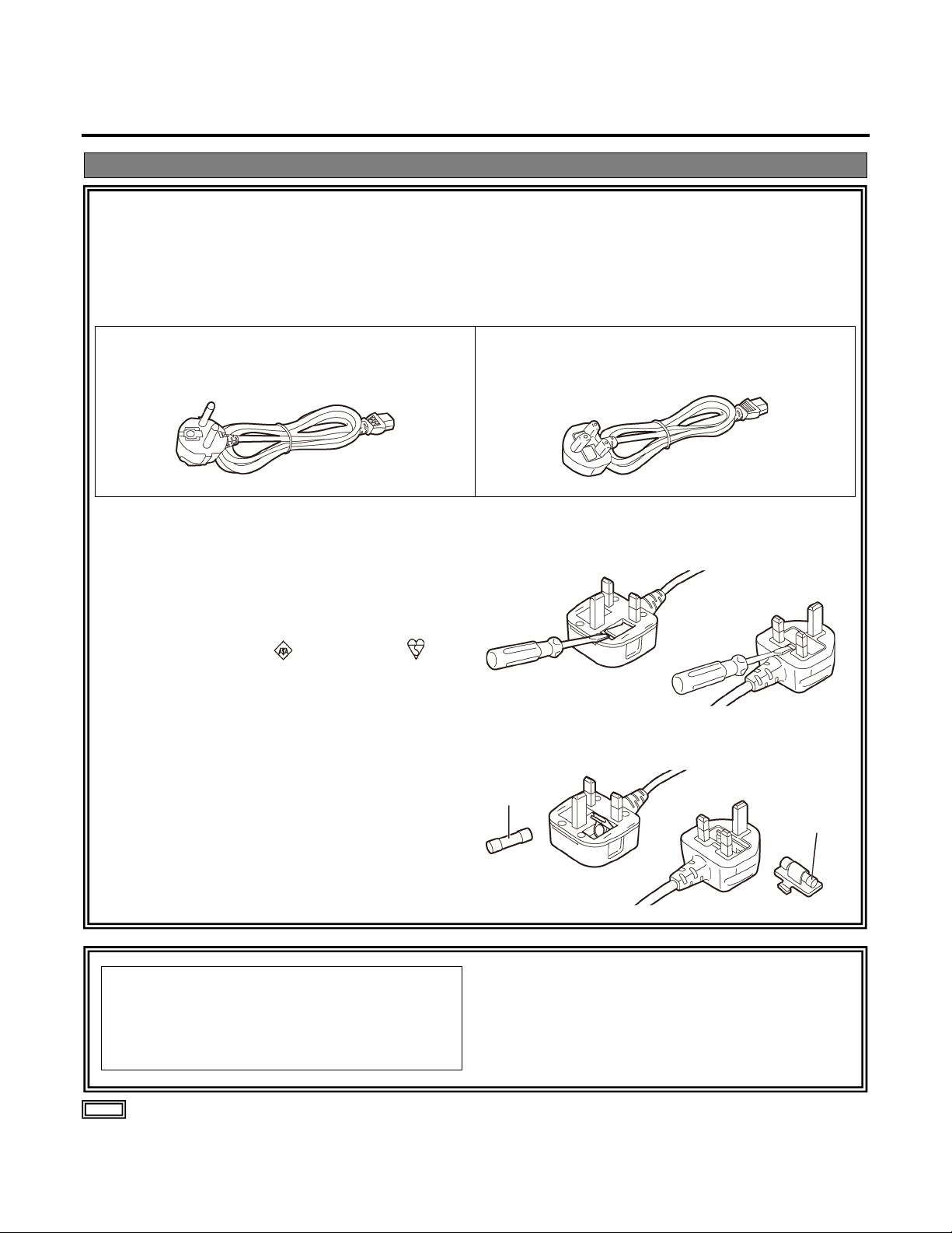
For AV-HLC100E
Caution for AC Mains Lead
FOR CONTINENTAL EUROPE, ETC.
FOR U.K. ONLY
FOR U.K. ONLY
How to replace the fuse
WARNING:
cause radio interference.
or
or
Fuse
Fuse
FOR YOUR SAFETY PLEASE READ THE FOLLOWING TEXT CAREFULLY.
This product is equipped with 2 types of AC mains cable. One is for continental Europe, etc. and the
other one is only for U.K.
Appropriate mains cable must be used in each local area, since the other type of mains cable is not suitable.
Not to be used in the U.K.
This appliance is supplied with a moulded three pin
mains plug for your safety and convenience.
A 13 amp fuse is fitted in this plug.
Should the fuse need to be replaced please ensure
that the replacement fuse has a rating of 13 amps
and that it is approved by ASTA or BSI to BS1362.
Check for the ASTA mark or the BSI mark on
the body of the fuse.
If the plug contains a removable fuse cover you must
ensure that it is refitted when the fuse is replaced.
If you lose the fuse cover the plug must not be used
until a replacement cover is obtained.
A replacement fuse cover can be purchased from
your local Panasonic Dealer.
If the plug supplied is not suitable for your socket
outlet, it should be cut off and appropriate one fitted.
1. Open the fuse compartment with a screwdriver.
2. Replace the fuse.
This equipment is compliant with Class A of
CISPR 32.
In a residential environment this equipment may
indicates safety information.
5

Read this first! (continued)
For AV-HLC100E
EMC NOTICE FOR THE PURCHASER/USER OF THE APPARATUS
4.Connect the apparatus to another power outlet where the power is not shared by any other appliances.
Turkey Only
AEEE Complies with Directive of Turkey.
1. Pre-requisite conditions to achieving compliance with the above standards
<1> Peripheral equipment to be connected to the apparatus and special connecting cables
• The purchaser/user is urged to use only equipment which has been recommended by us as peripheral equipment
to be connected to the apparatus.
• The purchaser/user is urged to use only the connecting cables described below.
<2> For the connecting cables, use shielded cables which suit the intended purpose of the apparatus.
• Video signal connecting cables
Use double shielded coaxial cables, which are designed for 75-ohm type high-frequency applications, for SDI
(Serial Digital Interface).
Coaxial cables, which are designed for 75-ohm type high-frequency applications, are recommended for analog
video signals.
• Audio signal connecting cables
If your apparatus supports AES/EBU serial digital audio signals, use cables designed for AES/EBU.
Use shielded cables, which provide quality performance for high-frequency transmission applications, for analog
audio signals.
• Other connecting cables (IEEE1394, USB)
Use double shielded cables, which provide quality performance for high-frequency applications, as connecting
cables.
• When connecting to the DVI signal terminal, use a cable with a ferrite core.
• If your apparatus is supplied with ferrite core(s), they must be attached on cable(s) following instructions in this
2. Performance level
manual.
The performance level of the apparatus is equivalent to or better than the performance level required by these standards.
However, the apparatus may be adversely affected by interference if it is being used in an EMC environment,
such as an area where strong electromagnetic fields are generated (by the presence of signal transmission
towers, cellular phones, etc.). In order to minimize the adverse effects of the interference on the apparatus in
cases like this, it is recommended that the following steps be taken with the apparatus being affected and with
its operating environment:
1.Place the apparatus at a distance from the source of the interference.
2.Change the direction of the apparatus.
3.Change the connection method used for the apparatus.
AEEE Yönetmeliğine Uygundur.
6
Read this first! (continued)
For AV-HLC100E
Manufactured by: Panasonic Corporation, Osaka, Japan
Winsbergring 15, 22525 Hamburg, Germany
Disposal of Old Equipment and Batteries
with the requirement set by the Directive for the chemical involved.
Importer’s name and address of pursuant to EU rules:
Panasonic Marketing Europe GmbH
Panasonic Testing Centre
Only for European Union and countries with recycling systems
These symbols on the products, packaging, and/or accompanying documents mean that
used electrical and electronic products and batteries must not be mixed with general
household waste.
For proper treatment, recovery and recycling of old products and used batteries, please take
them to applicable collection points in accordance with your national legislation.
By disposing of them correctly, you will help to save valuable resources and prevent any
potential negative effects on human health and the environment.
For more information about collection and recycling, please contact your local municipality,
dealer or supplier.
Penalties may be applicable for incorrect disposal of this waste, in accordance with national
legislation.
Note for the battery symbol (bottom symbol)
This symbol might be used in combination with a chemical symbol. In this case it complies
7

Contents
Read this first! ............................................................ 3
PART I Getting Started
Chapter 1 Accessories ......................................11
Chapter 2 Precautions for use .........................11
Chapter 3 About This Manual ...........................12
Chapter 4 Introduction ......................................13
Section 4.1 Overview ..........................................13
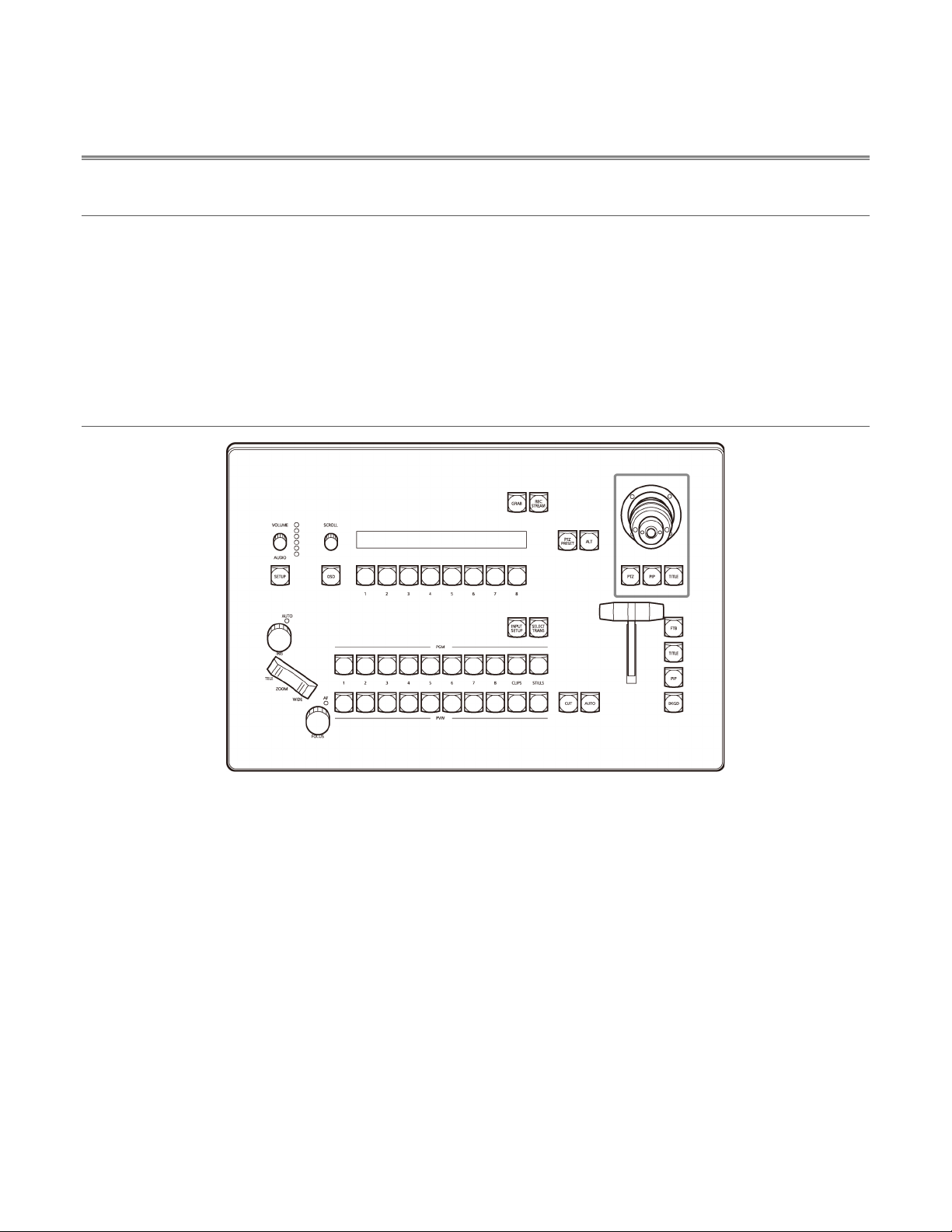
Section 4.2 Control Surface ................................13
Section 4.3 User Interface ...................................14
4.3.1 Administration Panel......................14
4.3.2 Live Desktop ..................................15
Section 4.4 Features ...........................................15
4.4.1 Physical .........................................15
4.4.2 Multi-Tier Failsafe ..........................16
4.4.3 A/V Input and Output .....................16
4.4.4 Skype TX .......................................16
4.4.5 Monitoring ......................................16
4.4.6 Video Processing...........................17
4.4.7 The Switcher ..................................17
4.4.8 Record and Stream .......................18
4.4.9 Automation ....................................18
4.4.10 Audio Mixer ....................................18
4.4.11 Integrated Clip and Still Players,
Plus Titles ......................................18
Chapter 5 Parts and their functions ................19
Section 5.1 Control Panel ...................................19
5.1.1 Camera control area ......................19
5.1.2 Switcher area .................................20
5.1.3 Audio area .....................................21
5.1.4 Menu control area..........................21
5.1.5 Grab & stream/record area ............22
5.1.6 Joystick area ..................................22
Section 5.2 Rear panel area ...............................23
Section 5.3 System configuration .......................24
Chapter 6 Setting Up .........................................25
Section 6.1 Command and Control .....................25
Section 6.2 Input Connections ............................26
6.2.1 Connect A/V Sources ....................26
Section 6.3 Output Connections .........................26
6.3.1 A/V Output .....................................26
Section 6.4 Tally Lights .......................................27
6.4.1 Connection Details ........................27
Section 6.5 Starting a Production Session ..........28
Section 6.6 The Administration Panel ................. 28
Section 6.7 The Live Desktop ............................. 29
Section 6.8 Configure Video Inputs .................... 29
Section 6.9 Configure Audio ............................... 31
6.9.1 Audio Headroom ........................... 33
Section 6.10 Networking ....................................... 33
PART II Reference
Chapter 7 Administration Panel ....................... 35
Section 7.1 Displaying the Administration Panel ...... 35
7.1.1 Video Settings ............................... 36
7.1.2 Utilities ........................................... 36
7.1.3 Title Page Defaults ........................ 39
7.1.4 Footer Tools .................................. 41
Chapter 8 Live Desktop .................................... 42
Section 8.1 Display Requirements ...................... 42
Section 8.2 Overview .......................................... 42
8.2.1 Control Types ................................ 43
Section 8.3 The Dashboard ................................ 44
8.3.1 File Menu ....................................... 45
8.3.2 Options Menu ................................ 45
8.3.3 Information Display ........................ 46
Section 8.4 Monitoring ........................................ 46
8.4.1 Program ......................................... 47
Chapter 9 Configure Video Sources ................ 49
Chapter 10 Switcher and Overlays .................... 58
8.4.2 Preview and Source Viewports ..... 47
8.4.3 Grab............................................... 48
8.4.4 Configuration Options.................... 48
Section 9.1 Input Settings Tab ............................ 49
9.1.1 Source Options .............................. 49
9.1.2 Input Names .................................. 52
9.1.3 PTZ (Connection) .......................... 52
Section 9.2 PTZ Tab ........................................... 53
9.2.1 Manual Navigation ......................... 54
9.2.2 PTZ Presets .................................. 54
9.2.3 PTZ and the Control Surface ........ 55
Section 9.3 Color Tab ......................................... 55
9.3.1 Auto Color ..................................... 56
9.3.2 Proc Amp ....................................... 56
Section 10.1 Switcher ........................................... 58
10.1.1 AUX Video Output ......................... 58
10.1.2 Understanding Video Layers ......... 59
Section 10.2 Switcher Transitions......................... 60
8

10.2.1 Presets ..........................................60
10.2.2 Duration .........................................60
Section 10.3 Overlays ...........................................61
10.3.1 Configuring Transitions .................61
10.3.2 Positioning .....................................62
10.3.3 Overlays and Transparency ..........63
10.3.4 Delegating Overlays ......................63
Chapter 11 Media Players ...................................64
Section 11.1 Playlists ............................................64
11.1.1 File Operations ..............................65
11.1.2 Properties ......................................65
11.1.3 Media Browser ...............................66
11.1.4 Player Controls ..............................67
Chapter 12 Title Editor ........................................68
Section 12.1 Edit tab .............................................69
12.1.1 Text Tools ......................................69
12.1.2 Stand-In Images ............................69
Section 12.2 DataLink ...........................................70
Section 12.3 Presets .............................................71
Chapter 13 Audio .................................................72
Section 13.1 Specifications ...................................72
Section 13.2 Headphones .....................................73
Section 13.3 VU Meters ........................................73
Section 13.4 External Sources ..............................73
13.4.1 Connection Type ...........................74
13.4.2 Analog Audio Input ........................74
Section 13.5 Skype TX and Mix Minus .................74
Section 13.6 TalkBack ..........................................74
Section 13.7 Common Controls ............................75
13.7.1 Mute ...............................................75
13.7.2 Solo ...............................................75
13.7.3 CLIP Player ...................................76
Section 13.8 Advanced Configuration ...................76
13.8.1 Audio Delay ...................................76
13.8.2 Pan ................................................77
13.8.3 Processing .....................................77
13.8.4 Automation ....................................79
Section 13.9 Output Control ..................................80
13.9.1 Headroom Notes ...........................80
Chapter 14 Stream/Record .................................81
Section 14.1 Installation ........................................81
Section 14.2 Overview ..........................................83
Section 14.3 Encoder Configuration .....................84
Section 14.4 Presets .............................................84
14.4.1 Custom Presets .............................85
14.4.2 Record (File Capture) ....................86
Section 14.5 Web Browser ....................................86
Section 14.6 Initiating the Stream ......................... 86
Section 14.7 Streaming Strategies ....................... 86
14.7.1 On Demand or Live Streaming? .... 86
14.7.2 Streaming Media Providers ........... 88
Section 14.8 Diagnostics and Troubleshooting ..... 89
14.8.1 Testing your stream ....................... 89
14.8.2 Speed Tests .................................. 92
14.8.3 Is it Really a Local Issue? ............. 92
Chapter 15 Control Surface ................................ 93
Section 15.1 Surface Layout ................................. 93
15.1.1 Control Groups .............................. 93
Section 15.2 Camera Controls .............................. 94
Section 15.3 Switcher Group ................................ 94
15.3.1 Program and Preview .................... 94
15.3.2 Switcher Delegates ....................... 95
15.3.3 Cut and Auto ................................. 95
15.3.4 Fader lever .................................... 95
15.3.5 Setup ............................................. 96
Section 15.4 Audio ................................................ 97
Section 15.5 Menu ................................................ 98
Section 15.6 Grab & Stream/Record .................... 99
Section 15.7 Joystick ............................................ 99
PART III Appendices
A. Performance Considerations ........................... 101
A.1 Testing, One Two … ...................................... 101
A.2 IMAG and Latency ......................................... 101
Relativity and the Speed of Light ............... 101
Latency and Your Audience ....................... 101
Latency and Your AV-HLC100 ................... 102
Other Sources of Latency ........................... 102
B. Keystroke Shortcuts ......................................... 104
C. Using Skype TX ................................................. 105
C.1 Skype TX Control Application ........................ 105
C.2 Connecting the Control Application to
AV-HLC100 .................................................... 106
D. Control Surface Menus..................................... 108
E. Appearance ........................................................ 114
F. Reliability Testing .............................................. 115
G. Specifications ................................................... 115
Index ....................................................................... 119
9

PART I Getting Started
Introducing Your Panasonic AV-HLC100 – connections and registration, a top-level overview of primary features,
and a hands-on tour to get you started.

AC adaptor ................................................................ 1
1
AV-HLC100E ............................................................. 2
Keyboard ................................................................... 1
1
Chapter 1 Accessories
Check that the following accessories are present and accounted for.
• After removing the product from its container, dispose of the power cable cap and packing materials in an
appropriate manner.
Power cable
Mouse .......................................................................
AV-HLC100P .............................................................
Chapter 2 Precautions for use
Condition for use
AV-HLC100 is only intended to be used by or operated under the supervision of responsible adults able to ensure
the safe operation of professional audio/video equipment.
Handle carefully.
Do not drop the product, or subject it to strong shock or vibration.
Do not carry or move the product by the fader lever. This is important to prevent malfunctioning or accidents.
Use the product in an ambient temperature of 0 °C to 40 °C (32 °F to 104 °F).
Avoid using the product at a cold place below 0 °C (32 °F) or at a hot place above 40 °C (104 °F) because
extremely low or high temperature will adversely affect the parts inside.
Power off before connecting or disconnecting cables.
Before plugging or unplugging the cables, be sure to switch power off.
Avoid humidity and dust.
Avoid using the product at a humid, dusty place because much humidity and dust will cause damage to the parts
inside.
Maintenance
Turn off the unit’s power and wipe the product using a dry cloth. To remove stubborn dirt, dip a cloth into a diluted
solution of kitchen detergent (neutral), wring it out well, and wipe the product gently.
Then, after wiping the product with a moist cloth, wipe it again with a dry cloth.
<Caution>
• Avoid using benzine, paint thinners and other volatile fluids.
• If a chemical cleaning cloth is to be used, carefully read through the precautions for its use.
Precaution to be observed during production
This product’s image switching and image effect functions can be used to produce images which flicker rapidly or
images which change rapidly.
However, bear in mind when using these functions in production that the kinds of images produced may have an
adverse effect on the viewer’s physical well-being.
When the product is to be discarded
When the product is to be discarded at the end of its service life, ask a specialized contractor to dispose of it
properly in order to protect the environment.
11

Chapter 3 About This Manual
These Operating Instructions are organized into the following sections:
PART I – Getting Started
Introduction to Panasonic AV-HLC100 – connecting devices (cameras, monitors, etc.).
PART II – Reference
This section covers the fine details of using your system (for those who need it, or simply like to know
everything there is to know).
PART III – Appendices
Leads off with a discussion of audio/video latency challenges. Appendix B lists all shortcut keys.
You will also find a comprehensive keyword index in Part III.
12
Chapter 4 Introduction
Section 4.1 Overview
Your Panasonic AV-HLC100 Live Production Center is a powerful video production system, supporting
web streaming and capture, internal media players, and an integrated control surface complete with PTZ
(pan-tilt-zoom) camera control.
AV-HLC100 lets you produce live video programs from diverse sources in high definition formats all the
way up to 1080/60p. The system fully supports NewTek’s innovative NDI (Network Device Interface)
protocol, placing it squarely in the forefront of IP video solutions.
Section 4.2 Control Surface
FIGURE 1
The small desktop footprint of this compact all-in-one unit is ideal for mobile applications, conference
rooms and any installations where space is limited.
AV-HLC100’s control surface (Figure 1) features a traditional video mixer’s Program and Preview row
configuration, with Cut and Auto buttons and Fader lever along with overlay (Picture in Picture and Title)
controls. It also features audio input and output controls, media players (Clip and Still), and a 3-axis
joystick to control up to eight individual PTZ cameras.
13
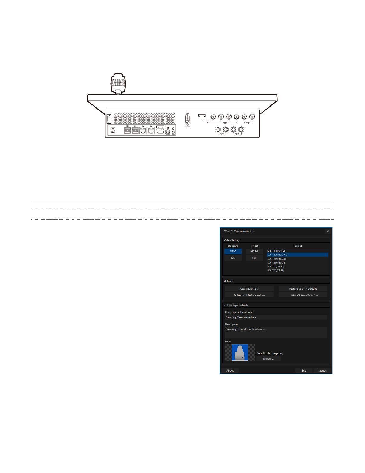
FIGURE 3
The rear panel provides a wealth of state-of-the-art a/v connectivity (Figure 2). Keyboard, mouse and
external storage solutions can be connected to the USB 3.0 connectors at left, while a monitor for the
user interface is supported by nearby HDMI and Display ports.
FIGURE 2
Connect HDMI and SDI video sources, or use the two network inputs for a/v input and output using NDI
(Network Device Interface) supported by many video products – including a number of Panasonic
professional cameras.
Section 4.3 User Interface
4.3.1 Administration Panel
AV-HLC100’s appears shortly after you first launch your
system. This is where you determine the video format you
wish to work in, but it also provides access to a number of
utilities, settings, and information.
Note that the Administration panel is not shown each time you
launch AV-HLC100 thereafter. The settings you choose are
retained, as are any assets you might have imported, along
with configuration options for video and audio inputs and
control states.
Of course you can recall the Administration panel at will. It can
be displayed on launch from the Windows Start menu folder
named “Panasonic AV-HLC100”, or you can display it on Exit
from the Live Desktop.
Clicking the Launch button at lower right takes you directly to
the Live Desktop to begin production.
14
Monitoring
Dashboard
Video Mixer
FIGURE 4
4.3.2 Live Desktop
AV-HLC100’s live production features are all available from its Live Desktop (Figure 3).
The various features and controls and modules comprising the Live Desktop are arranged in horizontal
bands, as seen in Figure 4.
• The top-most band comprises a convenient and powerful Dashboard.
• The area just below the Dashboard is devoted to a multi-viewport monitoring display, providing
visibility of all connected video sources, Program output and Preview.
• The central Live Control section is home to the Video Mixer, Transitions, and Overlay channels,
including PiP (Picture in Picture) and Titles controls.
Let’s take time for a brief overview of just some of the key features of your AV-HLC100.
• Compact, sturdy chassis, with easily accessible audio, video, monitoring and network connectors
from the rear for convenient installation in industry standard configurations.
• Professional grade fader lever and 3-axis joystick for video mixing, PTZ control and more.
• Audio and video connectors (except HDMI) use industry standard BNC and ¼” (6.35 mm) TRS jacks.
• Fast USB 3.0 connectors support connectivity for external storage devices for capture.
• 15-pin DE-15 (‘VGA-style’) Tally output connector.
Section 4.4 Features
4.4.1 Physical
15
FIGURE 5
4.4.2 Multi-Tier Failsafe
‘Always on Air’ features provide multi-tiered redundant software failsafe mechanisms. To name just a few:
• AV-HLC100 also has a comprehensive integrated system restore feature. You can quickly restore
factory defaults, or create a custom drive image on another volume and either restore from that.
• Multiple software failsafe systems continually monitor and safeguard the live performance.
Recoverable software error conditions are quickly and unobtrusively dealt with.
4.4.3 A/V Input and Output
• Connect and switch up to 8 external video sources, and two internal sources. AV-HLC100
supports SDI video input and output, internal, NDI and *NDI|HX video sources, and both analog
and digital audio input and output.
* requires installation of the NewTek NDI|HX driver for Windows
®
.
• Distribute your program over two SDI outputs, which can carry the main program or another
individually selected video source.
• Transmit output to other NDI-enabled systems across the network. AV-HLC100’s NDI output can
substitute for multiple traditional outputs, without requiring an external distribution amp.
• Professional BNC connectors provide increased durability and reliability for camera connections.
• Control supported robotic (PTZ) cameras via network connection.
• Freely mix 16:9 or 4:3 SD formats, and output as UHD, HD and SD simultaneously.
• Media Player modules allow you to insert pre-recorded video and imagery into your live presentations.
®
• Select Microsoft
Windows® or Apple Macintosh computers on the same network as Switcher
inputs for your live productions using NDI Scan Converter clients.
• Mix and route internal and external audio sources, including analog or (digital) embedded audio.
4.4.4 Skype TX
• AV-HLC100’s support for Microsoft’s powerful Skype TX platform allows you introduce Skype
calls from almost anywhere in the world into your programs. Skype TX requires nothing more than
a network connection to an external computer running the (free) Skype TX control application that
provides call management.
4.4.5 Monitoring
AV-HLC100’s Live Desktop includes a large monitoring pane with multiple viewports showing Program
output and Look Ahead Preview monitors, along with all external sources and Media Players.
16
4.4.6 Video Processing
• Full 4:4:4:4 32-bit floating point internal processing of all video sources.
• Proc Amps, White Balance and Auto Color features for every source preserve pristine color fidelity.
4.4.7 The Switcher
AV-HLC100’s switcher and NewTek’s NDI (Network Device Interface) support puts countless video
sources at your fingertips.
FIGURE 6
VIDEO LAYERS AND TRANSITIONS
The Transition section of the Live Desktop provides powerful tools for arranging and displaying the
numerous video and graphic layers contributing to your ultimate program output.
FIGURE 7
• Freely hot-punch or transition external or internal video sources.
• PiP and Title sources are displayed in the interface by small full-motion confidence monitors.
• Use any of the hundreds of transitions supplied to reveal either Background or Overlay channels
with animated wipes, trajectories and dissolves.
• Select individual transition effects for any layer and adjust Speed, Reverse and Ping Pong options.
OVERLAY CHANNELS
FIGURE 8
• Display PiP or Titles independently with custom transitions.
• Independent Crop, Position, 3D Rotation, and Scale controls for each Overlay channel.
17

4.4.8 Record and Stream
• *Record your live-switched production, and easily grab still images from Program or external
inputs.
• *Stream to multiple Internet destinations for redistribution.
* Requires the NewTek Streaming for AV-HLC100 plugin.
4.4.9 Automation
Use AV-HLC100’s convenient audio Follow feature to ensure you hear the sources you want in your
audio mix based on visible Switcher sources.
4.4.10 Audio Mixer
AV-HLC100 provides extensive multi-channel audio control and management.
• Adjust and sweeten audio sources for your program manually or automatically. Control external
audio sources supplied via SDI, analog, or NDI.
• Control output levels for program and headphones.
• Extensive and flexible ‘audio follow video’ options.
• Exclusive or latched Solo controls.
• Independent 7-band EQ, Compressor/Limiter and Noise Gate for each source and output.
• Configurable VU meter scales: Show VU meter calibration as digital (dBFS) or analog (dBVU or
dBu).
4.4.11 Integrated Clip and Still Players, Plus Titles
• Create playlists including a/v clips, sound files or still image files.
• Trim and re-order playlist entries.
• Flexible playback controls include variable Speed and Loop options.
• Control Clips player volume and other advanced audio options in the Audio Mixer.
• Autoplay feature starts and stops Clips playback automatically based on Switcher activity.
• Edit titles live, even while ‘on air’.
• Quickly switch between 8 different title presets.
• Automatically update text values in title pages based on media metadata.
®
• Import layered Photoshop
PSD files and automatically convert these to live-editable title pages.
18
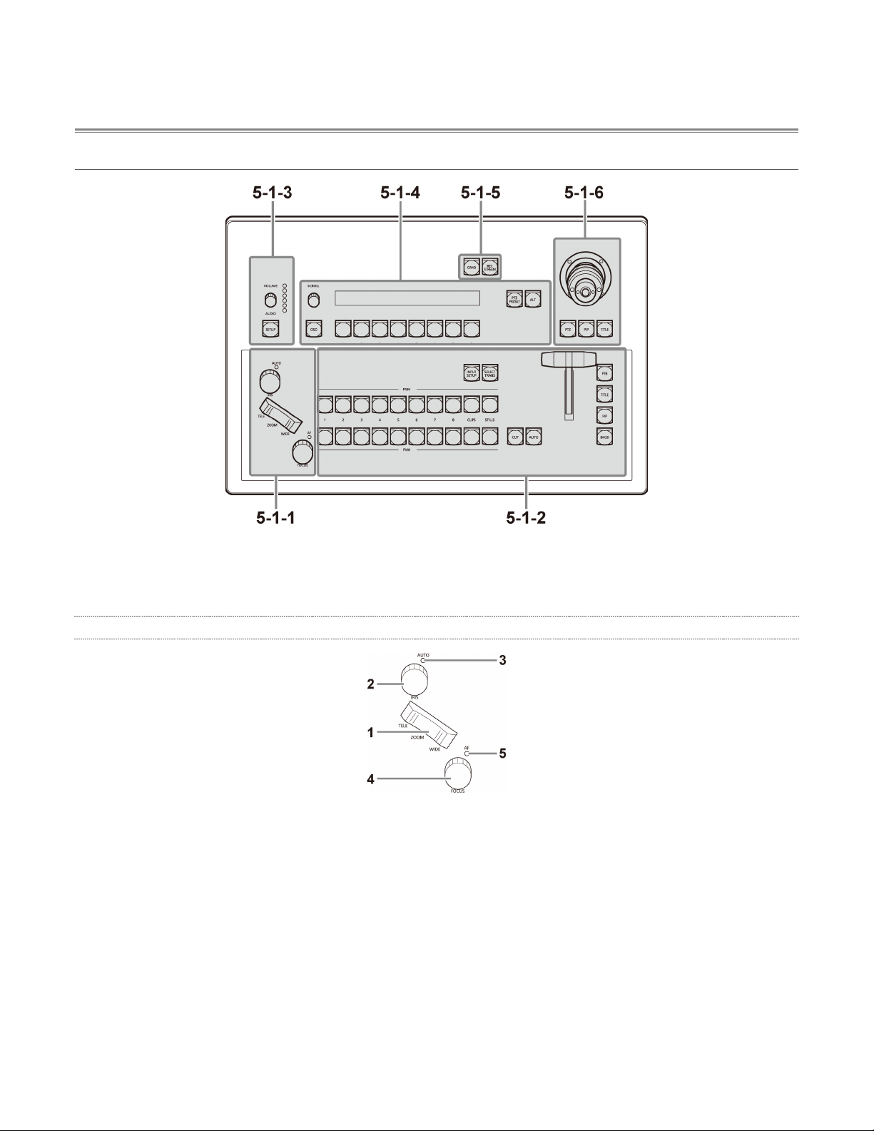
Chapter 5 Parts and their functions
Section 5.1 Control Panel
5-1-1. Camera control area
5-1-2. Switcher area
5-1-3. Audio area
1. [ZOOM] button
This adjusts the zoom of a camera connected to the network.
Press the [TELE] button to enlarge (zoom in), and
the [WIDE] button reduce (zoom out).
2. [IRIS] dial
This manually adjusts the iris of the camera lens.
• Turn the dial clockwise to operate the iris in the open direction,
and counterclockwise to operate it in the close direction.
3. [AUTO] indicator
This lights in red when automatic adjustment of
the iris is enabled.
• Check the iris setting (auto/manual) on the
camera. For details, refer to the operating
instructions of the camera.
5-1-4. Menu control area
5-1-5. Grab & stream/record area
5-1-6. Joystick area
5.1.1 Camera control area
4. [FOCUS] dial
This manually adjusts the focus of the camera lens.
• Turn the dial clockwise to move the focus
farther away, and counterclockwise to move it
nearer.
5. [AF] indicator
This lights in red when automatic adjustment of
the focus is enabled.
• Check the focus setting (auto/manual) on the
camera. For details, refer to the operating
instructions of the camera.
19
5.1.2 Switcher area
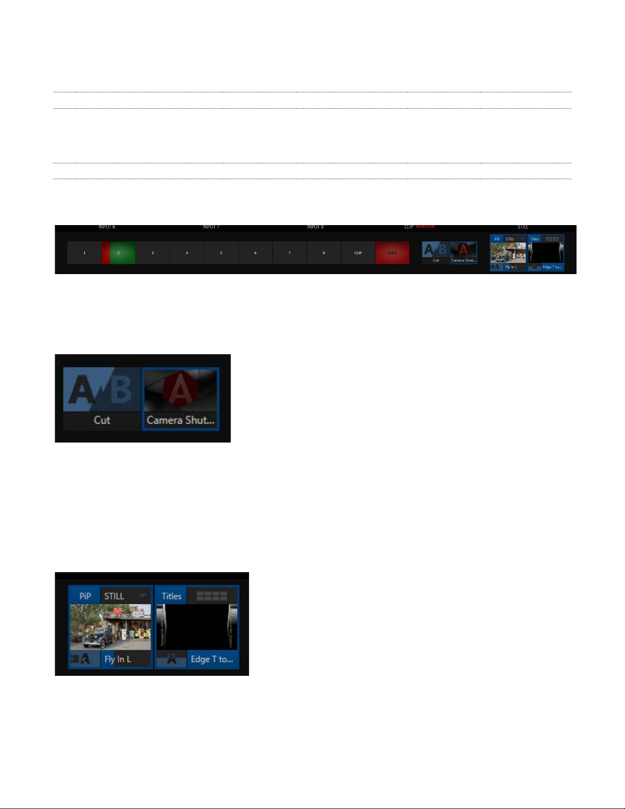
1. Program bus selection buttons
[PGM 1 to 8/CLIPS/STILLS]
These select the video source (background) for
program output. The button of the selected video
signal lights in red.
2. Preview bus selection buttons
[PVW 1 to 8/CLIPS/STILLS]
These select the video source for preview output.
The button of the selected video signal lights in
green.
3. [INPUT SETUP] button
This sets the video source to input.
• When the [INPUT SETUP] button is pressed, a
list of the video sources appears on the LED
display in the menu control area. Select the
video source to input with the menu selection
buttons.
4. [SELECT TRANS] button
This selects the transition of the video layer.
• When the [SELECT TRANS] button is pressed,
the preset numbers of the transitions appear on
the LED display in the menu control area.
Select the preset to use with the menu selection
buttons.
5. [CUT] button
This executes a straight cut for all selected video
layers (title, picture-in-picture, and video source).
6. [AUTO] button
This executes the transition assigned to the
selected video layer.
• Pressing the [AUTO] button during transition
execution allows you to stop operation. Press it
once again to complete the operation.
7. Fader lever
This controls the selected video layer.
8. [FTB] button
This fades the program output to a black screen.
9. [TITLE] button
Press this to control the display of the title page.
10. [PIP] button
Press this to control the display of the picture-inpicture (PIP).
11. [BKGD] button
Press this to control the display of the video
source.
20
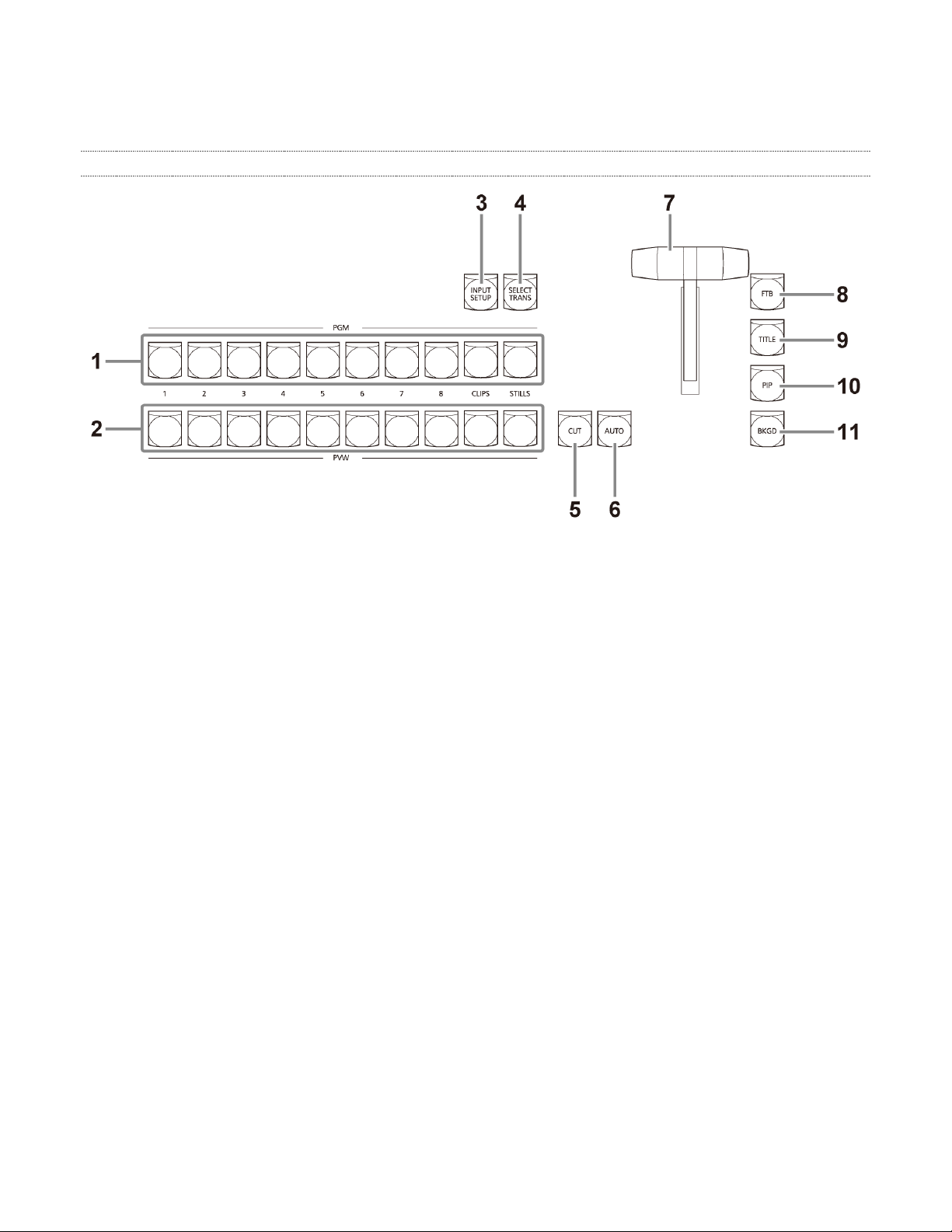
5.1.3 Audio area
1. [VOLUME] dial
This adjusts the volume level.
2. Volume indicator
This indicates the volume level.
• When lit in red, it indicates that clipping has
occurred.
3. [SETUP] button
This configures the settings of each audio channel.
• When the [SETUP] button is pressed, a list of
the audio sources appears on the LED display
in the menu control area. Select an audio
source with the menu selection buttons and
then configure the necessary settings.
5.1.4 Menu control area
1. [SCROLL] dial
This changes the page to display on the LED display.
• Turn the dial to change the page, and press it to
return to the previous display.
2. LED display
This displays various menus.
• The same menu as the input setting panel
([Color] tab) of the live desktop is displayed.
3. [PTZ PRESET] button
This displays the preset list of the camera being
controlled by the joystick on the LED display.
4. [ALT] button
This is used to operate the functions (PTZ PRESET,
etc.) of the menu control area.
5. [OSD] button
This displays the OSD menu of a camera connected
to the network.
• The settings of the OSD menu can be changed
with the buttons and dials of the menu control
area.
6. Menu selection buttons
These select the menus and options displayed on the
LED display.
21
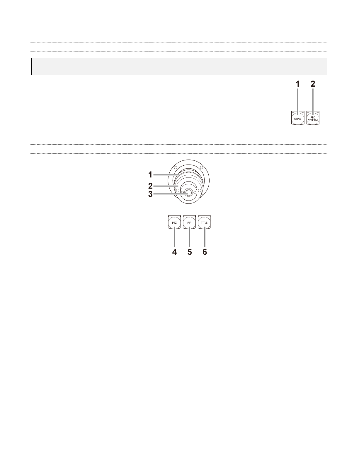
5.1.5 Grab & stream/record area
Note: The following two buttons are enabled only when the NewTek Streaming for AV-HLC100 plugin
is installed.
1. [GRAB] button
This captures a still image from the program output.
2. [REC/STREAM] button
This switches between the STREAM and RECORD functions on the dashboard of the live desktop.
5.1.6 Joystick area
1. Joystick
This controls the function of each of the [PTZ], [PIP],
and [TITLE] buttons.
2. Adjustment ring
Turn this ring to adjust the function (zoom/focus)
selected with the top button.
3. Top button
Each press of this button switches the function of the
adjustment ring (zoom/focus).
4. [PTZ] button
This selects the camera to control using each of the
buttons in the menu control area.
5. [PIP] button
This allows you to move and resize the picture-inpicture (overlay) using the joystick.
6. [TITLE] button
This allows you to move and resize the title (overlay)
using the joystick.
22
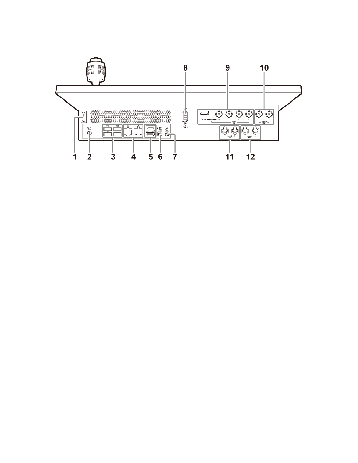
Section 5.2 Rear panel area
1. Power switch
Press the [
the unit. To turn off the power, press the [
] button to turn on the power and start up
] button
again.
2. Power input socket
Connect the supplied AC adaptor.
3. USB connectors
Connect a keyboard and mouse.
4. LAN connectors (RJ-45)
Connect with a local network using a LAN cable.
5. HDMI/DP connectors
Connect with an external computer monitor using an
HDMI cable or DisplayPort cable.
6. [LINE OUT] connector
This outputs audio.
7. [MIC] connector
This inputs audio.
8. [TALLY] connector
Connect an external tally light or similar device.
• External tally output occurs only when switched
to VIDEO IN 1 to 4. Output does not occur for a
camera connected via the network. For details,
refer to the operating instructions.
9. VIDEO IN connectors
These input video signals (HDMI or SDI) from an
external device.
10. SDI VIDEO OUT connectors
These output SDI video signals to an external device.
11. Analog AUDIO IN connectors
These input analog audio signals from an external
device (audio mixer, etc.).
12. Analog AUDIO OUT connectors
These output analog audio signals to an external
device.
23
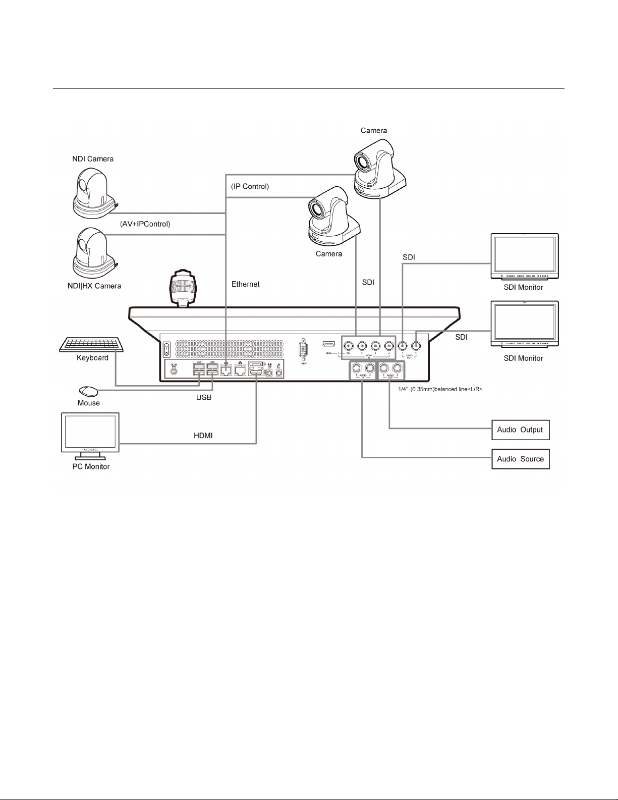
Section 5.3 System configuration
24
A word about UPS devices:
Chapter 6 Setting Up
To begin, let’s review ‘what came in the box’:
• Panasonic AV-HLC100
• A/C power supply
• Mouse and keyboard
• Print inserts
Section 6.1 Command and Control
Hint: The graphical user interface requires a minimum monitor resolution of 1600x900 pixels.
1. Connect an external computer monitor to either of the ports in the HDMI/Display group on the
motherboard backplate at left on AV-HLC100’s rear.
2. Connect the mouse and keyboard to nearby USB ports.
3. Turn on the computer monitor.
4. Connect the power cord to an A/C power receptacle,
and the round power connector to the matching input
connector at left on the motherboard backplate.
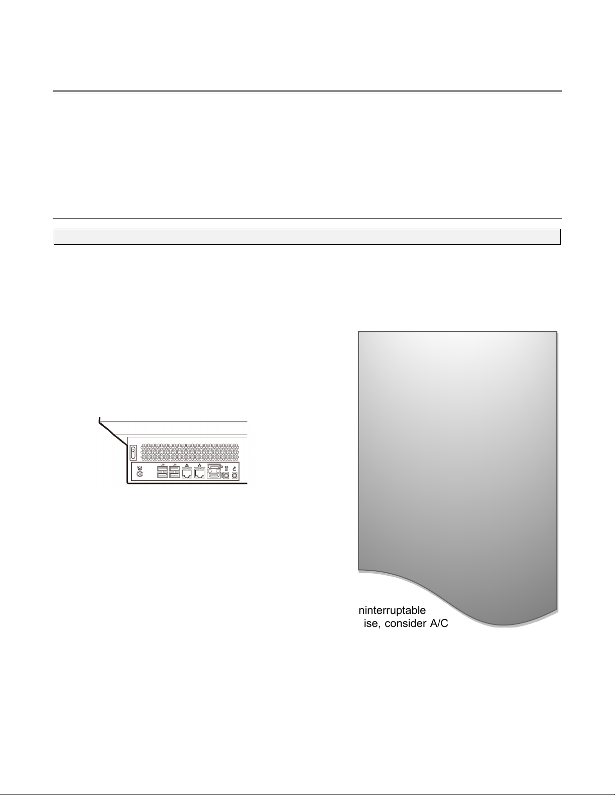
5. Press the Power rocker switch located just above the
power input connector on AV-HLC100’s rear panel.
FIGURE 9
6. (Optional) Connect AV-HLC100 to your local network
using the standard RJ-45 Ethernet connector on the
motherboard backplate (Figure 9).
At this point, the LED display will illuminate. (If this does not
happen, check your connections and retry).
Though not a requirement, we do encourage the use of an uninterruptable
power supply (UPS), as for any ‘mission critical’ system. Likewise, consider A/C
“power conditioning”, especially in situations where local power is unreliable or ‘noisy’.
(Surge protection is especially important in some locales.)
‘Modified sine wave’ UPS devices
are popular due to low manufacturing
costs. However, such units should
generally be viewed as being of low
quality and possibly inadequate to
fully protect the system from
abnormal power events.
For a modest added cost, consider a
"pure sine wave" UPS. These units
can be relied on to supply very clean
power, eliminating potential
problems, and are recommended for
applications demanding high
reliability.
Power conditioners can reduce wear on power supplies and other electronics, and provide a further
measure of protection from surges, spikes, lightning and high voltage.
25
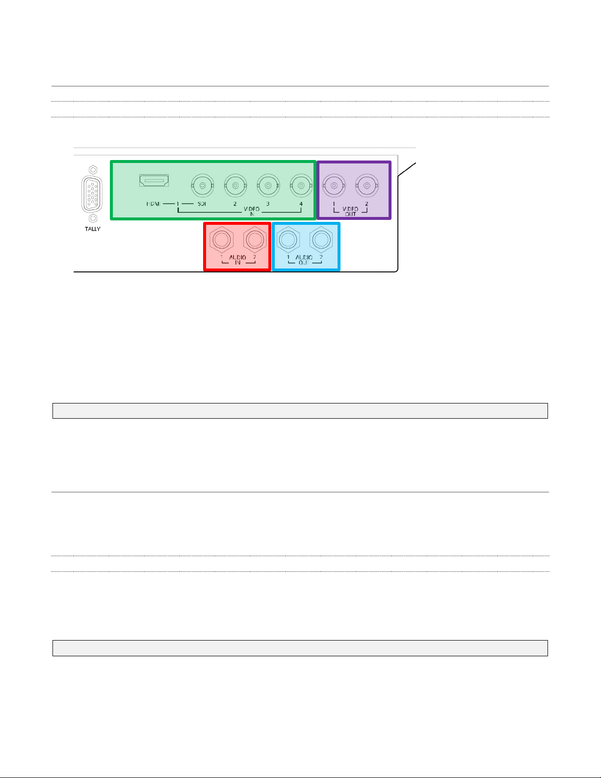
Section 6.2 Input Connections
6.2.1 Connect A/V Sources
FIGURE 10
• Analog audio inputs
• Analog audio outputs
• Video Inputs 1-4
• SDI Video Outputs
1. Connect local SDI or HDMI video sources to connectors in the VIDEO IN section (note that input
1 can be used to connect and HDMI source or an SDI one, but not both at once).
Note: Video sources with embedded audio do not necessarily require separate audio connections.
2. Connect any analog audio sources you wish to use (such as output from an external audio mixer)
to the Audio IN jacks; note that these are Line level, balanced audio inputs.
Section 6.3 Output Connections
Next we’ll discuss the audio and video output connectors along with relevant settings. We’ll start with
video output, not only so you can view your results but because certain items are best considered before
beginning production.
6.3.1 A/V Output
AV-HLC100 provides two SDI video output connectors, and a stereo pair of analog audio outputs.
1. Connect downstream video production devices to the connectors in the SDI OUT section as
desired.
Hint: The output video format is configured in the Administration panel (see Section 7.1.1).
2. Network (NDI and Stream) output obviously requires a network connection; in addition to optional
add-on software, streaming usually also requires an Internet connection.
26

FIGURE 11
THE VIDEO FORMAT FOR NDI OUTPUTS IS HANDLED AUTOMATICALLY. NDI MERELY
REQUIRES A NETWORK CONNECTION TO COMMUNICATE WITH NDI-ENABLED SYSTEMS
ON THE SAME NETWORK.
3. Connect external audio devices to the connectors in the AUDIO OUT section.
Section 6.4 Tally Lights
Tally Light support allows you to connect external tally lights and similar devices. These typically
provide a red LED for the video input that is currently selected on the Switcher’s Program row.
(NDI outputs also natively support tally over the network, without a separate connection.)
6.4.1 Connection Details
Here is a pin-out listing for the HD15 Tally connector:
• Pin1 – LED1
• Pin2 – LED2
• Pin3 – LED3
• Pin4 – LED4
• Pin5 – unused
Engineering Notes
• Pin6 – unused
• Pin7 – unused
• Pin8 – unused
• Pin9 – GND
• Pin10 – GND
• Pin11 – unused
• Pin12 – unused
• Pin13 – unused
• Pin14 – 3.3V (20 Ohms current limit)
• Pin15 – unused
Pins 1-4 are ‘hot’ when the LED should be illuminated.
Each LED pin (1 – 4) has a 200 ohm current limiting resistor inside AV-HLC100.
With no load (open circuit) the LED pins can reach 5V. With a typical LED load, they can be expected
to reach about 3V.
To prevent damage to internal components when making connections to the tally light jacks, care
should be taken that connection to Pins designated GND (Ground) are always at ground potential.
27
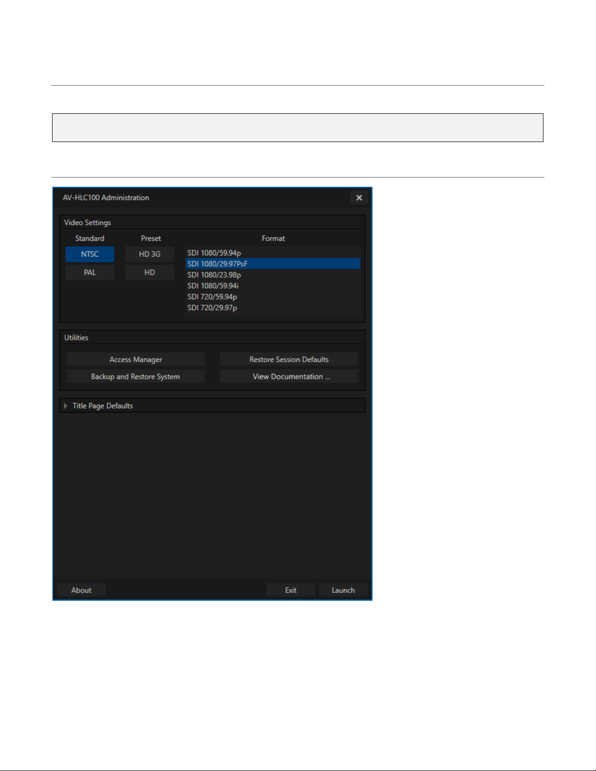
Section 6.5 Starting a Production Session
1. If AV-HLC100 is not already running, power it up now to reveal the Administration panel.
Hint: If the Live Desktop is already visible you may need to use the File menu item “Exit to
Administration” to return to the Administration panel.
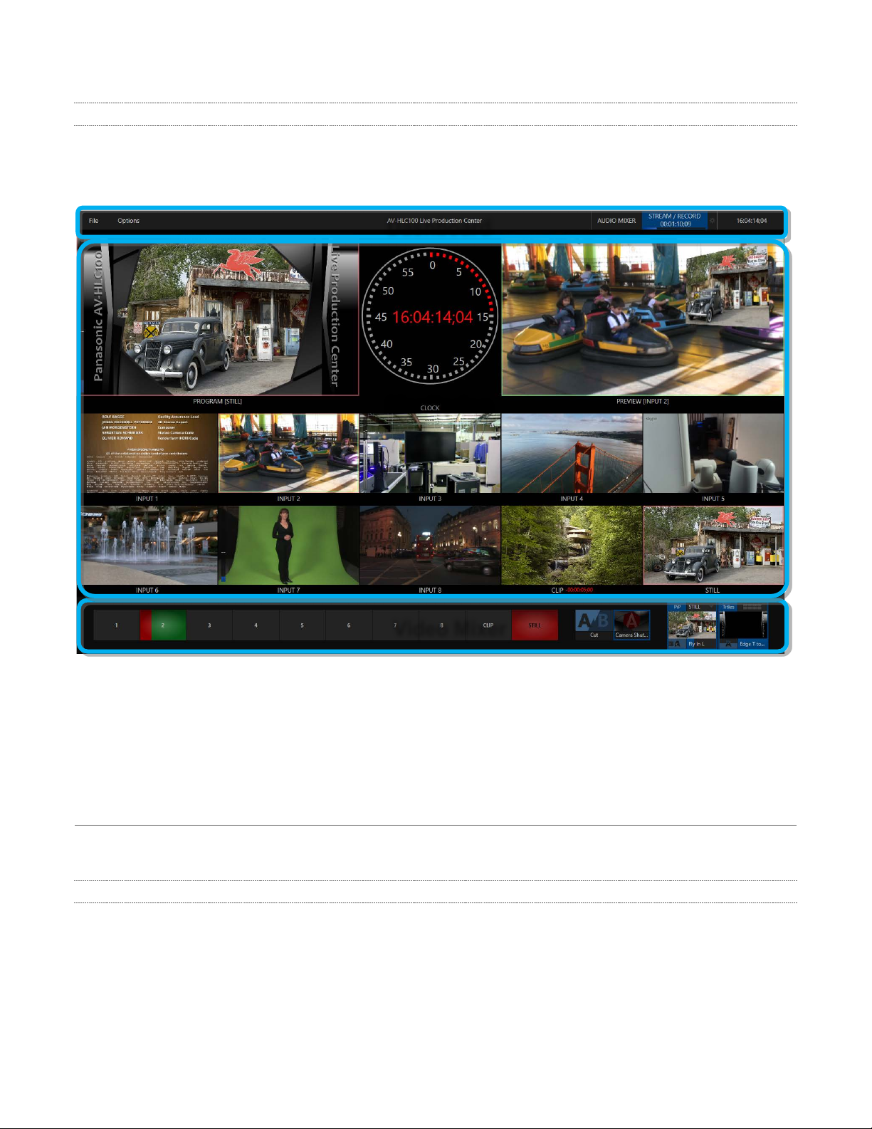
Section 6.6 The Administration Panel
FIGURE 12
2. Continue preparing for production by designating the video Standard used in your locale, either
NTSC or PAL under the heading Video Settings.
3. For now, click the nearby HD 3G format preset button (even if the cameras you plan to connect
output something different).
4. Finally, click the Launch button at the bottom of the panel.
28
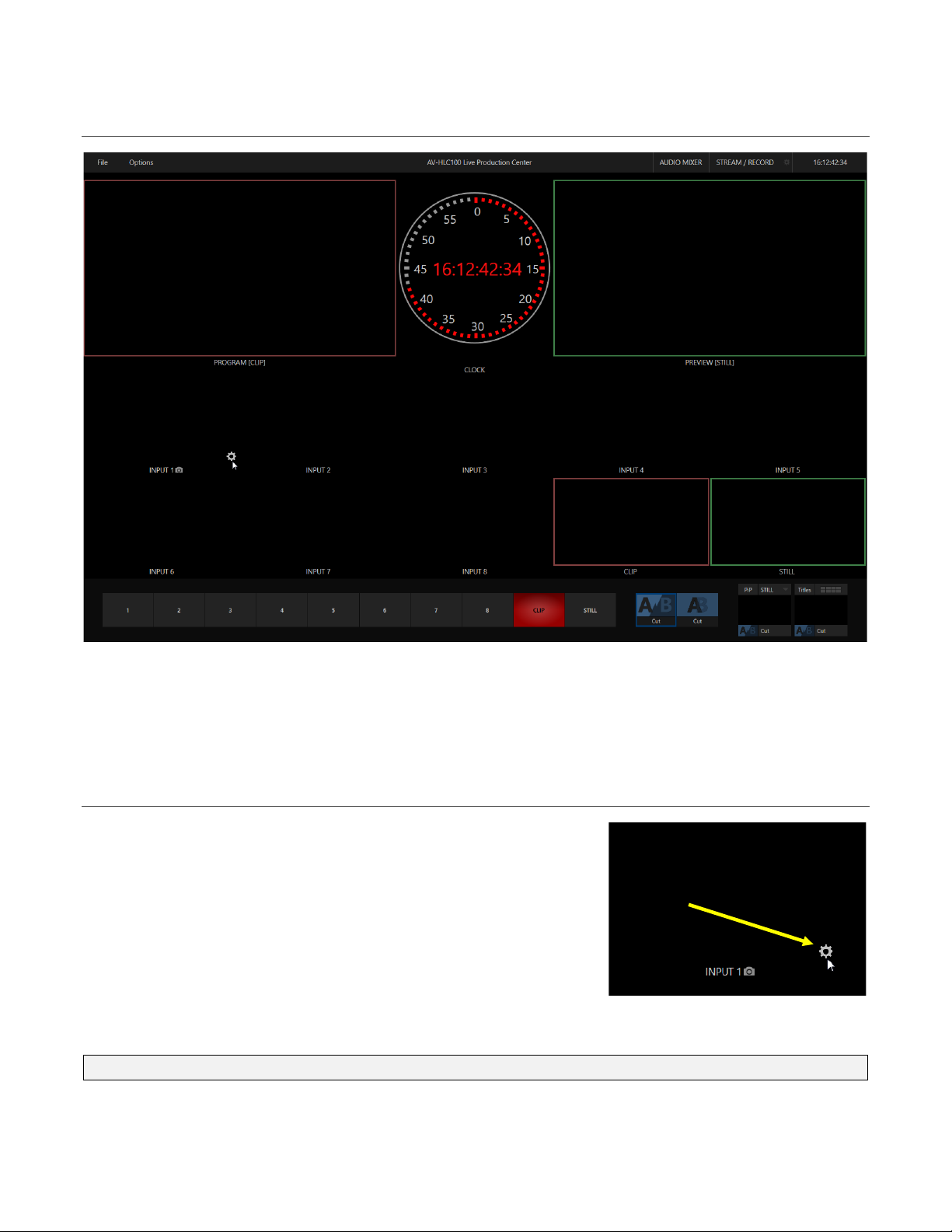
FIGURE 14
Section 6.7 The Live Desktop
FIGURE 13
Initially, as you have not yet configured inputs or added content, the Live Desktop looks a bit barren
(Figure 13). Take a quick look around, but then let’s continue to configure your devices. (We had a brief
glimpse at the Live Desktop back in 4.3.2, but we’ll examine it more closely in Chapter 8.)
Section 6.8 Configure Video Inputs
Source selection settings for video inputs can be accessed in the
Live Desktop’s monitoring section, so let’s spend a few moments
there. We’ll look into this in depth in the Reference Section of this
manual, but for now let’s configure the video sources you connected
earlier (Section 6.2.1).
1. Move your mouse over the viewport for INPUT 1, and notice
that a Configure button (gear icon) appears on it at lowerright.
2. Click this Configure button to open a tabbed settings panel.
Hint: As a quicker way to access the Input configuration panel, simply double-click the viewport.
29
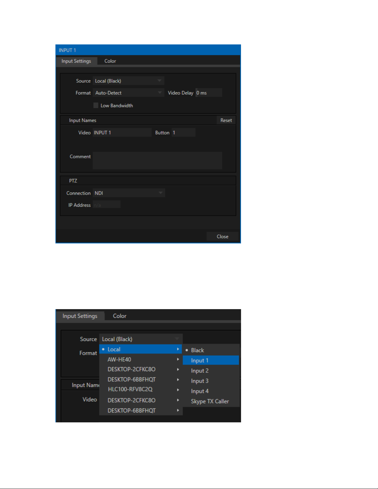
FIGURE 15
3. Click the Source drop-down menu to see a list of available sources (Figure 16). The Local inputs,
Black and Input 1-4, are listed first along with the Skype TX Caller option which we will discuss
later. NDI (Network Device Interface) sources discovered by AV-HLC100 are grouped below
under headings identifying channel(s) provided by the source device, or in some cases, device
type.
FIGURE 16
30
 Loading...