

Page 1
AV3,AVM3/AVT3,AVL3
VDE
FS FS-T
NEW SUBMINIATURE
SWITCHES
WITH HIGH PRECISION
FEATURES
• Consistent quality and high
precision through sophisticated
automatic fabrication system —O.P.:
8.4±0.3 mm (O.P.of conventional
subminiature switches: 8.4±0.5)
• Flux-resistant construction with
integrally molded terminals
• Solder terminal; Self-standing,
internationally common pitch, right
angle, left angle terminals for PC
board; Quick connect .110 terminals
for easy mounting
• Insulation guard available for safety
mounting
AV (FS•FS-T)
SWITCHES
• 2 lever pivot positions available for
applications where low operating
force is required
TYPICAL
APPLICATIONS
• Communication equipment
• Vending machines
• Security systems
• Data systems
• Medical equipment
• VCR
Compliance with RoHS Directive
PC board thickness:
1.6 mm
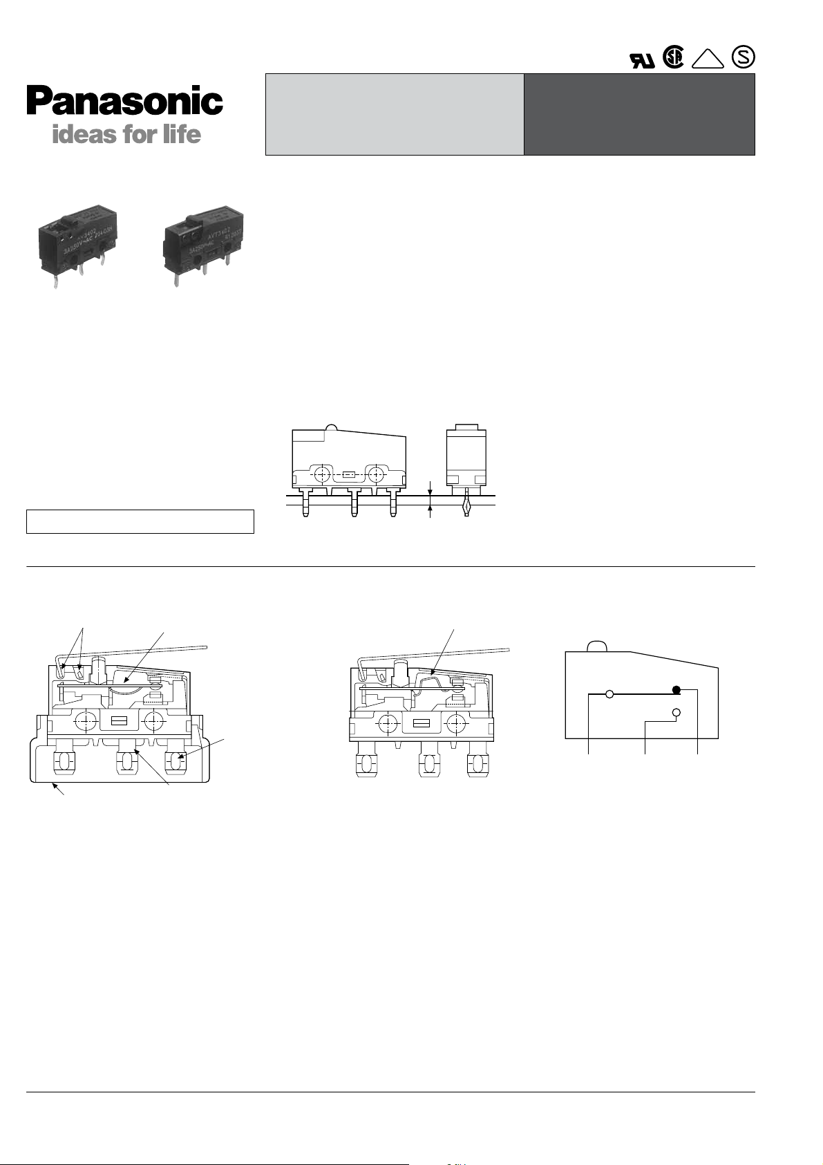
CONSTRUCTION (Example: AV3/AVM3 type)
Standard version Long life version
2 lever pivot positions
Optional insulation guard
Remark: As for FS-T switches, the terminals are the different shape.
Spring
Solder-terminal
Self-standing PC terminal
.110 Quick connect terminal
Flux resistant construction
Arch-shaped independent spring
CONTACT
ARRANGEMENT
COM NCNO
All Rights Reserved © C
OPYRIGHT Panasonic Electric Works Co., Ltd.
Page 2
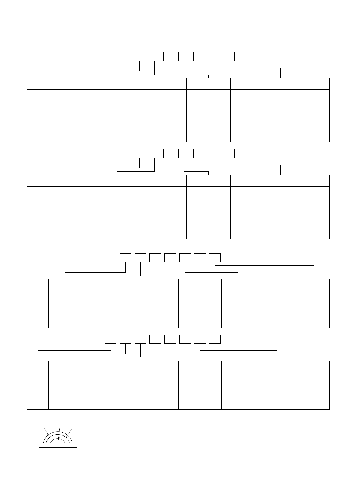
ORDERING INFORMATION
Au CuNi AgNi
1.FS switches
Ex. AV 3 2 0 2 3
AV3,AVM3/AVT3,AVL3
Type of
switch
AV3(FS)
switch
Type of
switch
AV3
(FS long
life ver.)
switch
Version
3: Standard 0: Pin plunger
Version
M3: Long life 0: Pin plunger
2.FS-T switches
Te r minals Actuators Contacts
1: Solder terminal with guard
2: Solder terminal without guard
3: Solder terminal with opposite
side guard
4: Self-standing PC terminal
5: Internationally common pitch
PC terminal
6: Right angle terminal
7: Left angle terminal
8: .110 Quick-connect terminal
Ex. AV M3 2 0 2 3
Te r minals Actuators Contacts
1: Solder terminal with guard
2: Solder terminal without guard
3: Solder terminal with opposite
side guard
4: Self-standing PC terminal
5: Internationally common pitch
PC terminal
6: Right angle terminal
7: Left angle terminal
8: .110 Quick-connect terminal
1: Short hinge
lever
2: Hinge lever
3: Long hinge
lever
4: Simulated
roller lever
5: Roller lever
1: Short hinge
lever
2: Hinge lever
3: Long hinge
lever
4: Simulated
roller lever
5: Roller lever
Operating force by
pin plunger, max.
0: 0.25 N
(Gold-clad
contact only)
2: 0.49 N
4: 0.98 N
Operating force by
pin plunger, max.
5: 1.47 N
Lever
position
Nil: Standard
[11: forward]
Lever
position
Nil: Standard
[11: forward]
Nil: AgNi alloy
61: Gold-clad
triple layer*
Nil: AgNi alloy
61: Gold-clad
triple layer*
International
standard
3: UL/CSA/
VDE/
SEMKO
International
standard
3: UL/CSA/
VDE/
SEMKO
Type of
switch
AVT3
(FS-T)
switch
Type of
switch
AVL3
(FS-T
long life
ver.)
switch
Version
T3: Standard 0: Pin plunger
Version
L3: Long life 0: Pin plunger
2: Solder terminal
4: PC terminal
8: .110 Quick-connect
terminal
2: Solder terminal
4: PC terminal
8: .110 Quick-connect
terminal
* Gold-clad triple layer contact
Ex. AV T3 2 0 2 3
Te r minals Actuators Contacts
1: Short hinge lever
2: Hinge lever
3: Long hinge lever
4: Simulated roller
lever
5: Roller lever
Operating force by
pin plunger, max.
0: 0.25 N
(Gold-clad
contact only)
2: 0.49 N
4: 0.98 N
Lever
position
Nil: Standard
[11: forward]
Nil: AgNi alloy
(Not applicable
to 0.25 N type)
61: Gold-clad
triple layer*
Ex. AV L3 2 0 2 3
Te r minals Actuators Contacts
1: Short hinge lever
2: Hinge lever
3: Long hinge lever
4: Simulated roller
lever
5: Roller lever
Operating force by
pin plunger, max.
5: 1.47 N
Lever
position
Nil: Standard
[11: forward]
Nil: AgNi alloy
(Not applicable
to 0.25 N type)
61: Gold-clad
triple layer*
Agency
standard
3: UL/CSA/
VDE/
SEMKO
Agency
standard
3: UL/CSA/
VDE/
SEMKO
All Rights Reserved © C
OPYRIGHT Panasonic Electric Works Co., Ltd.
Page 3
AV3,AVM3/AVT3,AVL3
APPLICABLE CURRENT RANGE
ContactType
Standard
version
Long life
version
Remark: For high capacity contact rating up to 10.1 A, please refer to PS (AVM3P) switches catalog.
Silver alloy contact
Gold-clad triple layer
contact type
Silver alloy contact
Gold-clad triple layer
contact type
1mA 100mA 3A 5A
Rating
O.F.
PRODUCT TYPES
1. FS switches (In-line terminal type)
Standard type
AgNi alloy contact
type
Gold-clad triple layer
contact type
Actuator
Pin plunger
Short hinge lever
Hinge lever
Long hinge lever
Simulated roller lever
Roller lever
Pin plunger
Short hinge lever
Hinge lever
Long hinge lever
Simulated roller lever
Roller lever
Operating force,
Max.
0.49N AV32023 AV31023 AV33023 AV34023 AV35023
0.98N AV32043 AV31043 AV33043 AV34043 AV35043
0.20N AV32123 AV31123 AV33123 AV34123 AV35123
0.39N AV32143 AV31143 AV33143 AV34143 AV35143
0.16N AV32223 AV31223 AV33223 AV34223 AV35223
0.34N AV32243 AV31243 AV33243 AV34243 AV35243
0.12N AV32323 AV31323 AV33323 AV34323 AV35323
0.25N AV32343 AV31343 AV33343 AV34343 AV35343
0.16N AV32423 AV31423 AV33423 AV34423 AV35423
0.34N AV32443 AV31443 AV33443 AV34443 AV35443
0.20N AV32523 AV31523 AV33523 AV34523 AV35523
0.39N AV32543 AV31543 AV33543 AV34543 AV35543
0.25N AV3200613 AV3100613 AV3300613 AV3400613 AV3500613
0.49N AV3202613 AV3102613 AV3302613 AV3402613 AV3502613
0.98N AV3204613 AV3104613 AV3304613 AV3404613 AV3504613
0.098N AV3210613 AV3110613 AV3310613 AV3410613 AV3510613
0.20N AV3212613 AV3112613 AV3312613 AV3412613 AV3512613
0.39N AV3214613 AV3114613 AV3314613 AV3414613 AV3514613
0.078N AV3220613 AV3120613 AV3320613 AV3420613 AV3520613
0.16N AV3222613 AV3122613 AV3322613 AV3422613 AV3522613
0.34N AV3224613 AV3124613 AV3324613 AV3424613 AV3524613
0.12N AV3232613 AV3132613 AV3332613 AV3432613 AV3532613
0.25N AV3234613 AV3134613 AV3334613 AV3434613 AV3534613
0.16N AV3242613 AV3142613 AV3342613 AV3442613 AV3542613
0.34N AV3244613 AV3144613 AV3344613 AV3444613 AV3544613
0.20N AV3252613 AV3152613 AV3352613 AV3452613 AV3552613
0.39N AV3254613 AV3154613 AV3354613 AV3454613 AV3554613
Without guard With guard
Self-standing solder terminal
1.47 N0.98 N0.49 N0.25 N
Part No.
With opposite
side guard
Self-standing
PC terminal
Internationally
common pitch
PC terminal
All Rights Reserved © C
OPYRIGHT Panasonic Electric Works Co., Ltd.
Page 4
AV3,AVM3/AVT3,AVL3
Actuator
Pin plunger
Short hinge lever
AgNi alloy contact
type
Gold-clad triple layer
contact type
Remark: When ordering, please refer to “Remarks” of ordering information.
Hinge lever
Long hinge lever
Simulated roller lever
Roller lever
Pin plunger
Short hinge lever
Hinge lever
Long hinge lever
Simulated roller lever
Roller lever
Operating force,
Max.
0.49N AV36023 AV37023 AV38023
0.98N AV36043 AV37043 AV38043
0.20N AV36123 AV37123 AV38123
0.39N AV36143 AV37143 AV38143
0.16N AV36223 AV37223 AV38223
0.34N AV36243 AV37243 AV38243
0.12N AV36323 AV37323 AV38323
0.25N AV36343 AV37343 AV38343
0.16N AV36423 AV37423 AV38423
0.34N AV36443 AV37443 AV38443
0.20N AV36523 AV37523 AV38523
0.39N AV36543 AV37543 AV38543
0.25N AV3600613 AV3700613 AV3800613
0.49N AV3602613 AV3702613 AV3802613
0.98N AV3604613 AV3704613 AV3804613
0.098N AV3610613 AV3710613 AV3810613
0.20N AV3612613 AV3712613 AV3812613
0.39N AV3614613 AV3714613 AV3814613
0.078N AV3620613 AV3720613 AV3820613
0.16N AV3622613 AV3722613 AV3822613
0.34N AV3624613 AV3724613 AV3824613
0.12N AV3632613 AV3732613 AV3832613
0.25N AV3634613 AV3734613 AV3834613
0.16N AV3642613 AV3742613 AV3842613
0.34N AV3644613 AV3744613 AV3844613
0.20N AV3652613 AV3752613 AV3852613
0.39N AV3654613 AV3754613 AV3854613
Part No.
Right angle terminal Left angle terminal .110 Quick-connect
All Rights Reserved © C
OPYRIGHT Panasonic Electric Works Co., Ltd.
Page 5

AV3,AVM3/AVT3,AVL3
2. FS-T switches (Cross-line terminal type)
Standard type
Operating force,
AgNi alloy contact
type
Gold-clad triple layer
contact type
Actuator
Pin plunger
Short hinge lever
Hinge lever
Long hinge lever
Simulated roller lever
Roller lever
Pin plunger
Short hinge lever
Hinge lever
Long hinge lever
Simulated roller lever
Roller lever
Part No.
Max.
0.49N AVT32023 AVT34023 AVT38023
0.98N AVT32043 AVT34043 AVT38043
0.20N AVT32123 AVT34123 AVT38123
0.39N AVT32143 AVT34143 AVT38143
0.16N AVT32223 AVT34223 AVT38223
0.34N AVT32243 AVT34243 AVT38243
0.12N AVT32323 AVT34323 AVT38323
0.25N AVT32343 AVT34343 AVT38343
0.16N AVT32423 AVT34423 AVT38423
0.34N AVT32443 AVT34443 AVT38443
0.20N AVT32523 AVT34523 AVT38523
0.39N AVT32543 AVT34543 AVT38543
0.25N AVT3200613 AVT3400613 AVT3800613
0.49N AVT3202613 AVT3402613 AVT3802613
0.98N AVT3204613 AVT3404613 AVT3804613
0.098N AVT3210613 AVT3410613 AVT3810613
0.20N AVT3212613 AVT3412613 AVT3812613
0.39N AVT3214613 AVT3414613 AVT3814613
0.078N AVT3220613 AVT3420613 AVT3820613
0.16N AVT3222613 AVT3422613 AVT3822613
0.34N AVT3224613 AVT3424613 AVT3824613
0.12N AVT3232613 AVT3432613 AVT3832613
0.25N AVT3234613 AVT3434613 AVT3834613
0.16N AVT3242613 AVT3442613 AVT3842613
0.34N AVT3244613 AVT3444613 AVT3844613
0.20N AVT3252613 AVT3452613 AVT3852613
0.39N AVT3254613 AVT3454613 AVT3854613
Solder terminal without
guard
PC terminal
.110 Quick-connect
terminal
All Rights Reserved © C
OPYRIGHT Panasonic Electric Works Co., Ltd.
Page 6
3. FS switches (In-line terminal type)
Long life version
Actuator
Pin plunger 1.47N AVM32053 AVM31053 AVM33053 AVM34053 AVM35053
Short hinge lever 0.59N AVM32153 AVM31153 AVM33153 AVM34153 AVM35153
AgNi alloy contact
type
Gold-clad triple layer
contact type
Hinge lever 0.54N AVM32253 AVM31253 AVM33253 AVM34253 AVM35253
Long hinge lever 0.44N AVM32353 AVM31353 AVM33353 AVM34353 AVM35353
Simulated roller lever 0.54N AVM32453 AVM31453 AVM33453 AVM34453 AVM35453
Roller lever 0.59N AVM32553 AVM31553 AVM33553 AVM34553 AVM35553
Pin plunger 1.47N AVM3205613 AVM3105613 AVM3305613 AVM3405613 AVM3505613
Short hinge lever 0.59N AVM3215613 AVM3115613 AVM3315613 AVM3415613 AVM3515613
Hinge lever 0.54N AVM3225613 AVM3125613 AVM3325613 AVM3425613 AVM3525613
Long hinge lever 0.44N AVM3235613 AVM3135613 AVM3335613 AVM3435613 AVM3535613
Simulated roller lever 0.54N AVM3245613 AVM3145613 AVM3345613 AVM3445613 AVM3545613
Roller lever 0.59N AVM3255613 AVM3155613 AVM3355613 AVM3455613 AVM3555613
Operating force,
Max.
Self-standing solder terminal
Without guard With guard
AV3,AVM3/AVT3,AVL3
Part No.
Internationally
common pitch
PC terminal
With opposite
side guard
Self-standing
PC terminal
Actuator
Pin plunger 1.47N AVM36053 AVM37053 AVM38053
Short hinge lever 0.59N AVM36153 AVM37153 AVM38153
AgNi alloy contact
type
Gold-clad triple layer
contact type
Remark: When ordering, please refer to “Remarks” of ordering information.
Hinge lever 0.54N AVM36253 AVM37253 AVM38253
Long hinge lever 0.44N AVM36353 AVM37353 AVM38353
Simulated roller lever 0.54N AVM36453 AVM37453 AVM38453
Roller lever 0.59N AVM36553 AVM37553 AVM38553
Pin plunger 1.47N AVM3605613 AVM3705613 AVM3805613
Short hinge lever 0.59N AVM3615613 AVM3715613 AVM3815613
Hinge lever 0.54N AVM3625613 AVM3725613 AVM3825613
Long hinge lever 0.44N AVM3635613 AVM3735613 AVM3835613
Simulated roller lever 0.54N AVM3645613 AVM3745613 AVM3845613
Roller lever 0.59N AVM3655613 AVM3755613 AVM3855613
Operating force,
Max.
4. FS-T switches (Cross-line terminal type)
Long life version
Actuator
Pin plunger 1.47N AVL32053 AVL34053 AVL38053
Short hinge lever 0.59N AVL32153 AVL34153 AVL38153
AgNi alloy contact
type
Gold-clad triple layer
contact type
Remark: When ordering, please refer to “Remarks” of ordering information.
Hinge lever 0.54N AVL32253 AVL34253 AVL38253
Long hinge lever 0.44N AVL32353 AVL34353 AVL38353
Simulated roller lever 0.54N AVL32453 AVL34453 AVL38453
Roller lever 0.59N AVL32553 AVL34553 AVL38553
Pin plunger 1.47N AVL3205613 AVL3405613 AVL3805613
Short hinge lever 0.59N AVL3215613 AVL3415613 AVL3815613
Hinge lever 0.54N AVL3225613 AVL3425613 AVL3825613
Long hinge lever 0.44N AVL3235613 AVL3435613 AVL3835613
Simulated roller lever 0.54N AVL3245613 AVL3445613 AVL3845613
Roller lever 0.59N AVL3255613 AVL3455613 AVL3855613
Operating force,
Max.
Part No.
Right angle terminal Left angle terminal .110 Quick-connect
Without guard With guard With opposite side guard
Part No.
Solder terminal Without
guard
PC terminal
.110 Quick-connect
terminal
All Rights Reserved © C
OPYRIGHT Panasonic Electric Works Co., Ltd.
Page 7

AV3,AVM3/AVT3,AVL3
SPECIFICATIONS
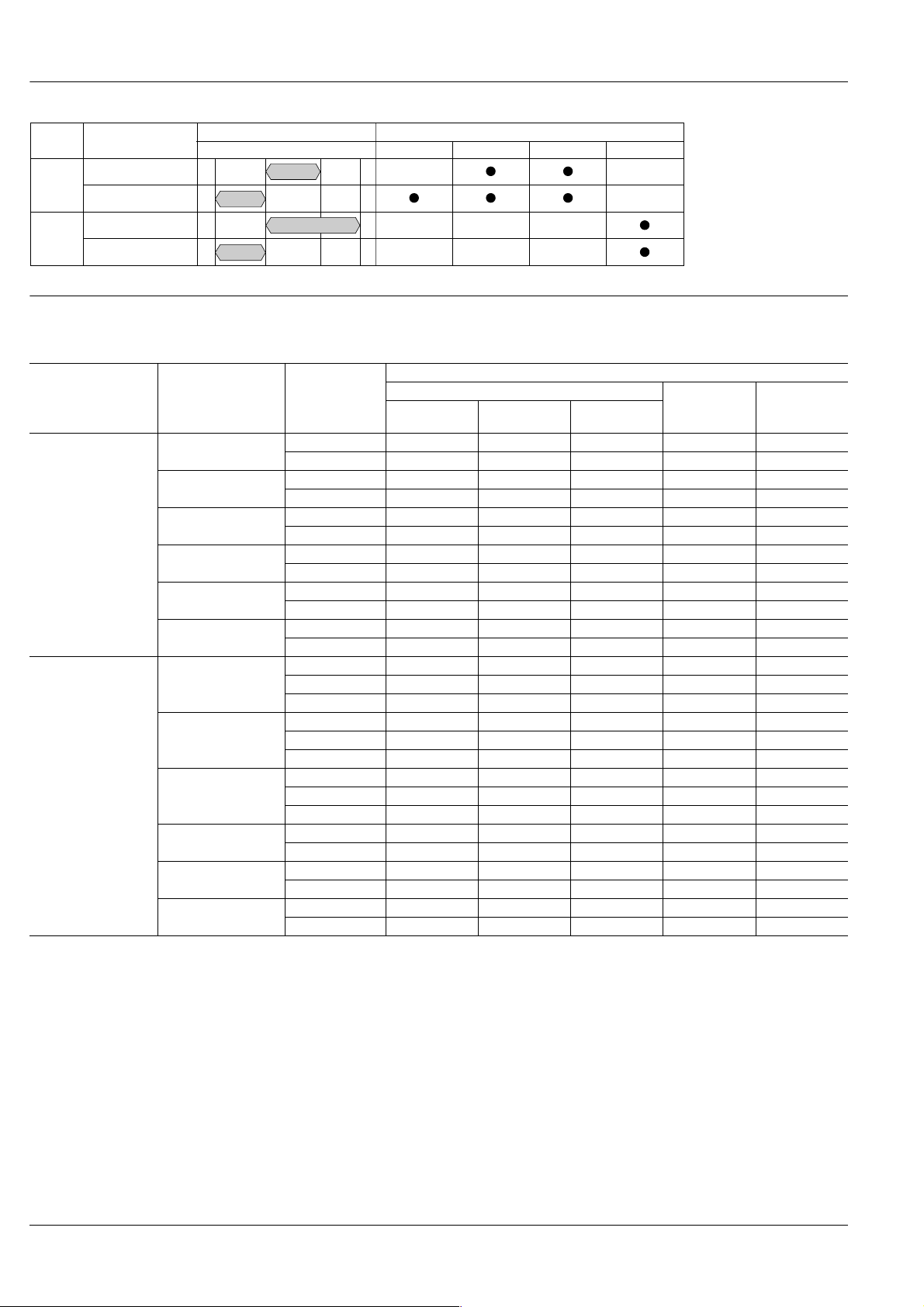
1.Contact rating
Standard version Long life version
Gold-clad contact
Voltage
125V AC 3A 2A 0.1A 5A 3A 0.1A
250V AC 3A 2A 0.1A 5A 3A 0.1A
30V DC 3A 2A 0.1A 5A 3A 0.1A
125V DC 0.4A 0.05A — 0.4A 0.05A —
Remark: Time constant shall be less than 7 msec. for DC inductive loads.
AgNi alloy contact type
Resistive load
(cosφ]1)
Inductive load
(cosφ]0.6-0.7)
type
Tr iple layer Triple layer
Resistive load
(cosφ]1)
AgNi alloy contact type
Resistive load
(cosφ]1)
Inductive load
(cosφ]0.6-0.7)
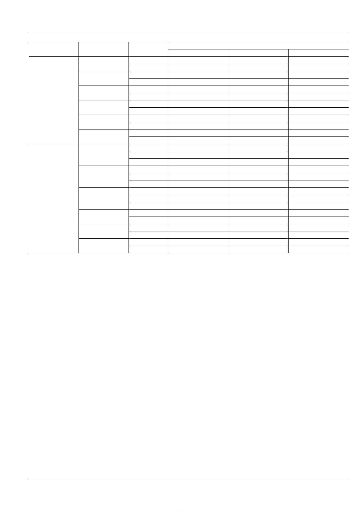
2.Characteristics
Standard version Long life version
AgNi alloy contact type Gold-clad contact type AgNi alloy contact type Gold-clad contact type
Electrical life at rated load (O.T.max.) 5 × 10⁴ at 20 cpm 2 × 10⁵ at 20 cpm 5 × 10⁴ at 20 cpm 2 × 10⁵ at 20 cpm
Mechanical life 5 × 10⁵ at 60 cpm (O.T.max.)
Insulation resistance Min.100MΩ at 500V DC
Dielectric strength
Between non-continuous terminals
Between each terminal and other
exposed metal parts
Between each terminal and ground
Vibration resistance (Pin plunger type) 10 to 55 Hz at single amplitude of 1.5mm (Contact opening: max.1 msec.)
2
Shock resistance (Pin plunger type)
(Contact opening: less than 1 msec.)
Contact resistance (Initial)
Allowable operating speed 0.1 to 1,000 mm/sec.
Max.operating cycle rate 300 cpm
Ambient temeprature –25°C to +85°C (no freezing below 0°C)
Unit weight Approx.2g
294 m/s
147 m/s2 min.
(by voltage drop 1 A
min.
(O.F. 0.98 N)
(O.F. 0.49 N)
50 mΩ max.
6 to 8V DC)
294 m/s2 min.
(O.F. 0.98 N)
147 m/s2 min.
(O.F. 0.49 N)
49 m/s2 min.
(O.F. 0.25 N)
100 mΩ max.
(by voltage drop 0.1 A
6 to 8V DC)
1,000 Vrms
1,500 Vrms
1,500 Vrms
Au: 50 mΩ max. (by voltage drop 0.1 A 6 to 8V DC)
Ag: 50 mΩ max. (by voltage drop 1 A 6 to 8V DC)
3 × 10⁷ (O.T.: Specified value)
107 (O.T.max.) at 60 cpm
294 m/s2 min.
3.Operating characteristics
1) Pin plunger
4th digit
number of
Part No.
0 0.25N 0.020N
O.F.max. R.F.min. P.T.max. M.D.max. O.T.max. O.P.
Gold-clad contact
type
Resistive load
(cosφ]1)
2 0.49N 0.074N
4 0.98N 0.15N
5 1.47N 0.20N
2) Short hinge lever
4th digit
number of
Part No.
0 0.098N 0.004N
2 0.20N 0.017N
4 0.39N 0.034N
5 0.59N 0.039N
O.F.max. R.F.min. P.T.max. M.D.max. O.T.max. O.P.
0.6mm 0.1mm 0.4mm
2.5mm 0.5mm 0.8mm
All Rights Reserved © C
OPYRIGHT Panasonic Electric Works Co., Ltd.
Distance from mounting holes: 8.4±0.3mm
Distance from stand-off:
FS 11.8±0.4mm
FS-T 11.7±0.4mm
Distance from mounting holes: 8.8±0.8mm
Distance from stand-off:
FS 12.2±0.9mm
FS-T 12.1±0.9mm
Page 8

3) Hinge lever
4th digit
number of
Part No.
0 0.078N 0.003N
O.F.max. R.F.min. P.T.max. M.D.max. O.T.max. O.P.
AV3,AVM3/AVT3,AVL3
2 0.16N 0.015N
4 0.34N 0.029N
5 0.54N 0.034N
4) Long hinge lever
4th digit
number of
O.F.max. R.F.min. P.T.max. M.D.max. O.T.max. O.P.
Part No.
0——
2 0.12N 0.012N
4 0.25N 0.025N
5 0.44N 0.029N
5) Simulated roller lever
4th digit
number of
Part No.
0——
2 0.16N 0.015N
4 0.34N 0.029N
O.F.max. R.F.min. P.T.max. M.D.max. O.T.max. O.P.
2.8mm 0.8mm 1.2mm
3.5mm 1.0mm 1.6mm
2.8mm 0.8mm 1.2mm
Distance from mounting holes: 8.8±0.8mm
Distance from stand-off:
FS 12.2±0.9mm
FS-T 12.1±0.9mm
Distance from mounting holes: 8.8±1.2mm
Distance from stand-off:
FS 12.2±1.3mm
FS-T 12.1±1.3mm
Distance from mounting holes: 11.65±0.8mm
Distance from stand-off:
FS 15.05±0.9mm
FS-T 14.95±0.9mm
5 0.54N 0.034N
6) Roller lever
4th digit
number of
O.F.max. R.F.min. P.T.max. M.D.max. O.T.max. O.P.
Part No.
0——
2 0.20N 0.017N
4 0.39N 0.034N
5 0.59N 0.039N
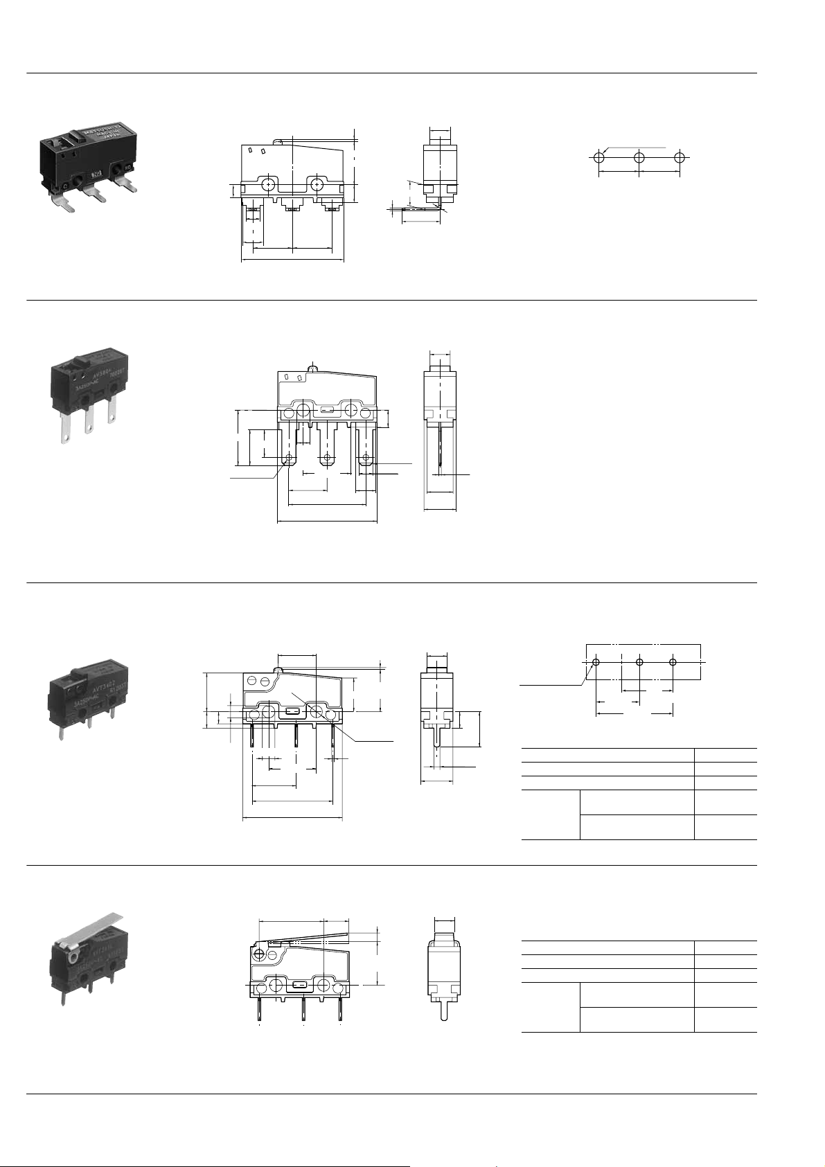
DIMENSIONS
1. FS switches (In-line terminal type)
1-(1) Solder terminal (without guard)
2.5mm 0.5mm 0.8mm
±0.15
3.4
7.4
NO
C
±0.15
8.7
15.4
19.8
NC
±0.2
2.8
±0.15
±0.3
Distance from mounting holes: 14.5±0.8mm
Distance from stand-off:
FS 17.9±0.9mm
FS-T 17.8±0.9mm
mm General tolerance: ±0.25
4.0
±0.2
1.85
±0.12
1.1
±0.12
1.5
0.5
±0.1
1.25
5.2
±0.2
6.4
Dimensions other than drawn above is same as self-standing PC board terminal.
All Rights Reserved © C
OPYRIGHT Panasonic Electric Works Co., Ltd.
Page 9

AV3,AVM3/AVT3,AVL3
1-(2) Solder terminal (with guard)
8.0
Dimensions other than drawn above is same as guardless type.
1-(3) Solder terminal (with opposite side guard)
8.0
Dimensions other than drawn above is same as guardless type.
mm General tolerance: ±0.25
NO
C
24.0
24.0
NC
1-(4) Self-standing PC terminal
Pin plunger
7.7
7.4
Short hinge lever
PC board pattern
±0.3
7.6
1.8
+0.1
2.4
-0.05
NO
C
NC
2.4
±0.1
2.5
±0.1
9.5
±0.15
8.7
±0.15
15.4
±0.3
19.8
12.85 5.0
(
)
P.T.
0.6 max.
(
)
O.P.
±0.3
8.4
6.7
±0.15
3.4
+0.1
2.4 dia.
-0.05
0.9
2.2
±0.1
2.2
(
)
P.T.
±0.4
2.5 max.
(
O.P.
11.8
1.25
4.0
)
±0.4
±0.2
1.85
±0.12
1.1
Pretravel, Max. mm 0.6
0.5
±0.1
±0.12
1.5
5.2
±0.2
6.4
Movement differential, Max. mm 0.1
Overtravel, Min. mm 0.4
Distance from mounting
Operating
position
hole, mm
Distance from standoff,
mm
4.0
Pretravel, Max. mm 2.5
(
)
O.P.
±0.8
(
O.P.
12.2
)
±0.9
6.6
NO
C
8.8
NC
Movement differential, Max. mm 0.5
Overtravel, Min. mm 0.8
Distance from mounting
Operating
position
hole, mm
Distance from standoff,
mm
3-1.2
8.7
±0.1
±0.05
15.4
dia.
±0.1
8.4±0.3
11.8±0.4
8.8±0.8
12.2±0.9
Hinge lever
±0.4
7.15
(
O.P.
8.8
NO
C
NC
All Rights Reserved © C
(
)
P.T.
2.8 max.
4.0
Pretravel, Max. mm 2.8
)
±0.8
(
)
O.P.
±0.9
12.2
Movement differential, Max. mm 0.8
Overtravel, Min. mm 1.2
Operating
position
OPYRIGHT Panasonic Electric Works Co., Ltd.
Distance from mounting
hole, mm
Distance from standoff,
mm
8.8±0.8
12.2±0.9
Page 10

Long hinge lever
Simulated roller lever
AV3,AVM3/AVT3,AVL3
mm General tolerance: ±0.25
(
)
P.T.
3.5 max.
±0.4
13.1
(
O.P.
±1.2
8.8
NO
C
C
NC
(
)
P.T.
±0.4
6.3
R2.5
NO
2.8 max.
(
)
O.P.
±0.8
11.65
(
O.P.
15.05
NC
)
(
O.P.
12.2
4.0
Pretravel, Max. mm 3.5
)
±1.3
4.0
Movement differential, Max. mm 1.0
Overtravel, Min. mm 1.6
Operating
position
Distance from mounting
hole, mm
Distance from standoff,
mm
8.8±1.2
12.2±1.3
Pretravel, Max. mm 2.8
Movement differential, Max. mm 0.8
)
±0.9
Overtravel, Min. mm 1.2
Operating
position
Distance from mounting
hole, mm
Distance from standoff,
mm
11.65±0.8
15.05±0.9
Roller lever
C
1-(5) Internationally common pitch PC terminal
2.4
3.2
7.4
6-C0.3
(4.0)
NO
1.3
7.62±0.1
19.8±0.3
5.15
±0.4
NC
7.62±0.1
(
P.T.
2.5 max.
(
O.P.
±0.8
14.5
(O.P.)
8.4±0.3
3.4±0.15
)
)
(
17.9
(P.T.)
0.6max.
(O.P.)
11.8±0.4
O.P.
3.2
5.0 dia.
Pretravel, Max. mm 2.5
)
±0.9
4.0
0.5
Movement differential, Max. mm 0.5
Overtravel, Min. mm 0.8
Operating
position
Distance from mounting
hole, mm
Distance from standoff,
mm
14.5±0.8
17.9±0.9
PC board pattern
3-1.5±0.05 dia.
7.62±0.1 7.62±0.1
1-(6) Right angle terminal
2.4
(2.8)
(4.0)
7.62±0.1
19.8±0.3
All Rights Reserved © C
7.62±0.1
(P.T.)
0.6max.
(O.P.)
8.4±0.3
3.4±0.15
R0.5
4.0
5.08±0.2
6.4
0.5
OPYRIGHT Panasonic Electric Works Co., Ltd.
PC board pattern
3-1.5±0.05 dia.
7.62±0.1 7.62±0.1
Page 11
AV3,AVM3/AVT3,AVL3
1-(7) Left angle terminal
mm General tolerance: ±0.25
1-(8) .110 Quick-connect terminal
2.4
(2.8)
(4.0)
7.1
11.0
±0.05
3-1.2 dia.
7.62±0.1
±0.15
±0.1
5.5
7.62±0.1
19.8±0.3
C
2.5
7.6
(P.T.)
0.6max.
(O.P.)
8.4±0.3
4.0
PC board pattern
3-1.5±0.05 dia.
7.62±0.1 7.62±0.1
5.08±0.2
3.4±0.15
0.5
6.4
R0.5
4.0
NO
NC
±0.15
3.4
±0.1
±0.1
9.5
±0.15
±0.15
15.2
±0.3
19.8
6-C0.6
2.8
4.0
±0.1
±0.1
0
-0.15
0.5
5.2
±0.2
6.4
Dimensions other than drawn above is same as self-standing PC board terminal.
2.FS-T switches (Cross-line terminal type)
2-(1) PC board terminal
Pin plunger
±0.3
7.6
+0.1
2.4
-0.05
7.7
2.4
3.3
NO
C
6.7
NC
2.4 dia.
±0.1
2.5
±0.1
9.5
0.5
8.8
16.1
±0.3
19.8
Short hinge lever
±0.4
12.85
C
5.0
NO
NC
(
P.T.
0.6 max.
(
O.P.
8.4
+0.1
-0.05
(
P.T.
2.5 max.
(
O.P.
±0.8
8.8
PC board pattern
)
4.0
7.0
3-1.35 to 1.50 dia.
8.8
±0.1
16.1
10.9
(Button position)
±0.1
Pretravel, Max. mm 0.6
Movement differential, Max. mm 0.1
Overtravel, Min. mm 0.4
Distance from mounting
Operating
position
hole, mm
Distance from standoff,
mm
11.7±0.4
Pretravel, Max. mm 2.5
Movement differential, Max. mm 0.5
Overtravel, Min. mm 0.8
Distance from mounting
Operating
position
hole, mm
Distance from standoff,
mm
12.1±0.9
8.4±0.3
8.8±0.8
)
±0.3
3.2
±0.1
1.2
±0.2
6.4
)
4.0
)
All Rights Reserved © C
OPYRIGHT Panasonic Electric Works Co., Ltd.
Page 12

Hinge lever
12.85
7.15
AV3,AVM3/AVT3,AVL3
mm General tolerance: ±0.25
±0.4
(
)
P.T.
2.8 max.
4.0
Long hinge lever
Simulated roller lever
O.P.
±0.8
8.8
NO
C
C
12.85
C
NC
(
)
P.T.
3.5 max.
±0.4
13.1
(
O.P.
8.8
NO
NC
(
±0.4
6.3
R2.5
NO
NC
P.T.
2.8 max.
(
O.P.
11.65
4.0
)
±1.2
)
4.0
)
±0.8
Movement differential, Max. mm 0.8
Overtravel, Min. mm 1.2
Operating
position
Distance from mounting
hole, mm
Distance from standoff,
mm
8.8±0.8
12.1±0.9
Pretravel, Max. mm 3.5
Movement differential, Max. mm 1.0
Overtravel, Min. mm 1.6
Operating
position
Distance from mounting
hole, mm
Distance from standoff,
mm
8.8±1.2
12.1±1.3
Pretravel, Max. mm 2.8
Movement differential, Max. mm 0.8
Overtravel, Min. mm 1.2
Operating
position
Distance from mounting
hole, mm
Distance from standoff,
mm
11.65±0.8
14.95±0.9
(
Pretravel, Max. mm 2.8
)
Roller lever
2-(2) Solder terminal
(
)
5.15
±0.4
P.T.
2.5 max.
(
O.P.
±0.8
14.5
3.2
5.0 dia.
)
Pretravel, Max. mm 2.5
Movement differential, Max. mm 0.5
Overtravel, Min. mm 0.8
NO
C
NC
Operating
position
(
)
6.7
2.4 dia.
0.5
P.T.
0.6 max.
(
O.P.
8.4
+0.1
-0.05
±0.3
)
1.8 dia.
6-C 0.3
4.0
(
)
3.9
6.4
1.5
±0.2
2.8
±0.2
6.4
±0.3
7.6
+0.1
7.7
2.4
-0.05
NO
C
2.4
3.3
±0.1
2.5
9.5
8.8
19.8
NC
±0.1
16.1
±0.3
Distance from mounting
hole, mm
Distance from standoff,
mm
14.5±0.8
17.8±0.9
As for the dimensions of lever types, dimensions other than terminals are same as self-standing solder terminal.
All Rights Reserved © C
OPYRIGHT Panasonic Electric Works Co., Ltd.
Page 13

AV3,AVM3/AVT3,AVL3
Ag
Au (-61)
Triple layer contact type
3 A
100 mA
1 mA
0
DC
AC
(Reference only)
5
5
15
30V
30 250V
2-(3) .110 Quick-connect terminal
(
)
6.7
2.4 dia.
0.5
P.T.
0.6 max.
(
O.P.
8.4
+0.1
-0.05
4.0
)
±0.3
±0.1
5.5
7.1
±0.1
2.8
6.4
±0.05
1.2 dia.
±0.2
±0.3
7.6
+0.1
2.4
-0.05
7.7
NO
C
2.4
3.3
±0.1
2.5
9.5
8.8
19.8
As for the dimensions of lever types, dimensions other than terminals are same as self-standing solder terminal.
NC
±0.1
16.1
±0.3
NOTES
1.Regarding fastening of switch body
In fastening the switch body, use flat
filister head M2.3 screws, with tightening
torque of not more than 0.29N·m.To
prevent loosening of the screws, it is
recommended that spring washers be
used with the screws and adhesive be
applied to lock the screws.
After mounting the switch and making
wiring connections, the insulation
distance between ground and each
terminal should be confirmed as
sufficient.
The positioning of the switch should be
such that the pushbutton or actuator for
the switch should not directly apply force
to the operating section in the free
condition.For a pushbutton, the force
from the pushbutton should be applied in
a perpendicular direction.
In setting the movement after operation,
the over-travel should be set not less
than 70% as a standard.Setting the
movement at less than 70% of O.T.may
cause troubles such as mis-contact and
welding due to small contact force of the
switch.
N.C.
side
Usable
area
Stroke
Contact
force
N.O.
side
0
70% of O.T.
specified value
O.T. spedified
value
P.T.
O.T. max.
2.Soldering operation
For manual soldering: 60W soldering
iron, soldering completed within 3
seconds; do not apply force to the
terminals.
For automatic soldering tank: 250°C
immersion, completed within 6 seconds,
350°C immersion, completed within 3
seconds.
Te r minal portions must not be moved in
min.1 minute after soldering.Also no
tensile strength of lead wires should be
applied to terminals.
3.Regarding connector connections
(.110 quick connect terminals)
For making connections, a dedicated
receptacle for .110 quick connect
terminals should be used, and the
terminals should be inserted parallel to
the receptacle.Consideration should be
given to mounting so that no tensile load
is applied to the lead wires.
4.In making the switch selection
Consideration should be given to provide
for no interference up to +20% variation
of the standard characteristics values.
5.Environment
Locations where corrosive gases having
a bad influence on contacts are present,
and locations where there is an
excessive amount of siliceous or other
abrasive dust should be avoided.
mm General tolerance: ±0.25
11.0
±0.15
6.Cautions regarding use
This subminiature switch has been
designed as a dedicated switch for AC
use, but it can be used for low capacity
DC circuits.
Please select gold-clad contact types
when loads are in the low-level area of
1mA up to 100mA and 5V up to 30V.
For switching of inductive loads (relays,
solenoids, buzzers, etc.), in order to
prevent damage to contacts due to the
occurrence of arcing, an arc absorbing
circuit should be applied
7.Quality check under Actual Loading
Condition
To assure reliability, check the switch
under actual loading conditions.Avoid any
situation that may adversely affect
switching performance.
8.When using lever type switch, care
should be taken not to apply undue
force on the body from the opposite
side or side ways to its operating
direction.
All Rights Reserved © C
OPYRIGHT Panasonic Electric Works Co., Ltd.
 Loading...