

Page 1
V-Log/V-Gamut
REFERENCE MANUAL
November 28, 2014
Page 2
Revision history
Revision Date Explanation
Rev.1.0 November 28, 2014 First Edition
Table of Contents
1. Introduction
2. Curve Characteristics
3. V-Log Formula
4. Colorimetric Information
5. Appendix
V-Log/V-Gamut REFERENCE MANUAL
1
Page 3
V-Log/V-Gamut REFERENCE MANUAL
1. Introduction
This document describes technical information on the log curve and gamut used in Panasonic’s
“Varicam” for utilization in recording and workflow composition.
V-Log has characteristics similar to a log curve of a scan from negative film and is highly compatible
with conventional firm workflow. Light information collected via a lens is converted to electronic
information by sensors. In other words, light information and electronic information have a proportional
relation. Log curve characteristics show the relationship between the linear domain video signal and
exposure measured in stops, and a change in each stop of exposure increases or decreases the signal by
almost the same amount.
2. Curve Characteristics
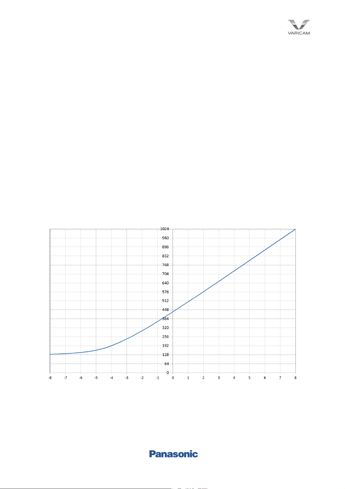
Fig. 2.1 shows the characteristics of V-Log. This graph is defined as the x axis being exposure and the
y axis being 10bit code values. Fig. 2.2 shows reflection and code assignment. Gray output code with
reflection of 18% is defined as 433, black output code with reflection of 0% as 128, and white output code
with reflection of 90% as 602. Varicam also supports 12bitV-Log output, and a value four times that of
10bit code is the output code with 12bit code.
Fig.2.1 V-Log characteristics
2
Page 4

Input reflection [%] V-Log
IRE [%] 10bit Code Value 12bit Code Value
0 7.3 128 512
18 42 433 1732
90 61 602 2408
Fig.2.2 V-Log Code Value
V-Log/V-Gamut REFERENCE MANUAL
3. V-Log Formula
3.1 Scene Linear Reflection to V-Log
The function for converting from linear signal to V-Log data is as follows. With linear reflection as “in”
and V-Log data as “out”,
out = 5.6*in+0.125 (in < cut1 )
out = c*log10(in+b)+d (in >= cut1 )
cut1 = 0.01, b=0.00873, c=0.241514, d=0.598206
However, 0<=out<=1
3.2 V-Log to Scene Linear Reflection
The function for reverting compressed V-Log data to linear refection is as follows. With V-Log data as
“in” and linear reflection as “out”,
out = (in - 0.125) / 5.6 (in < cut2 )
out = pow(10.0, ((in - d) / c)) – b (in >= cut2 )
cut2 = 0.181However, 0<=in<=1
3.3 V-Log 10bit code to Scene Linear Reflection
This shows an example of converting 10bit code value V-Log data to linear reflection using the
above-mentioned inverse function. However, V-Log 10bit code value is IN10BIT.
in = IN10BIT/1023
out = (in - 0.125) / 5.6 (in < cut2 )
out = pow(10.0, ((in - d) / c)) – b (in >= cut2 )
3
Page 5

V-Log/V-Gamut REFERENCE MANUAL
4. Colorimetric Information
4.1 V-Gamut
Super35mm Sensors in the Varicam 35 achieve wide color gamut V-Gamut by optimizing the on-chip
filter characteristics for splitting light into RGB. V-Gamut is therefore the optimum color space as a master
archive, and video production with high color reproducibility is possible by converting to P3DCI color
space and ITU-R BT.709 color space in post-processing. V-Gamut can also enable operation of
subsequent stage color conversion in a common conversion matrix through chromatic adaptation
processing.
The following is wide gamut RGB primary, and White point is defined in the D65 color space.
Fig.4.1 V-Gamut
x y
R 0.730 0.280
G 0.165 0.840
B 0.100 -0.030
White(D65) 0.3127 0.3290
Fig.4.2 V-Gamut RGB primary
4
Page 6

4.2 Gamut Conversion Matrix
The V-Gamut RGB to CIE 1931 XYZ conversion matrix is shown below.
0.679644 0.152211 0.118600
0.260686 0.774894 -0.035580
-0.009310 -0.004612 1.102980
The CIE 1931 XYZ to V-Gamut RGB conversion matrix is shown below.
1.589012 -0.313204 -0.180965
-0.534053 1.396011 0.102458
0.011179 0.003194 0.905535
V-Log/V-Gamut REFERENCE MANUAL
The V-Gamut RGB to ITU-R BT.709 RGB conversion matrix is shown below.
1.806576 -0.695697 -0.110879
-0.170090 1.305955 -0.135865
-0.025206 -0.154468 1.179674
The V-Gamut RGB to ACES RGB conversion matrix is defined as a matrix including chromatic adaptation
and is shown below.
0.724383 0.166748 0.108497
0.021354 0.985138 -0.006319
-0.009234 -0.001043 1.010273
5
Page 7

V-Log/V-Gamut REFERENCE MANUAL
5. Appendix
Here, the clip level of Varicam 35 (model number AU-V35C1G/AU-VREC1G) and Varicam HS (model
number AU-V23HS1G/AU-VREC1G) is expressed in 10bit code. Firmware version is shown individually.
Varicam 35 (Firmware version1.15 or higher)
ISO Clipping Level
10bit code
800 911
1000 911
1250 911
1600 911
2000 911
2500 911
3200 911
4000 911
5000 911
6400 911
8000 911
10000 911
12800 911
Varicam HS (Firmware version1.15 or higher)
ISO Clipping Level
10bit code
2500 896
3200 896
4000 896
5000 896
6400 896
8000 896
10000 896
12800 896
6
 Loading...