

Page 1

Arbitrator (ARB-SI) ver.1.9
Basic Operation
[For Officers]
Page 2

Arbitrator (ARB-SI) Ver.1.9 Basic Operation
(1) Control Reference Guide
for Officers
-Contents-
(2) SI (Front End Application) “LIVE” Mode Menu for Officer
(3) Record the video (“LIVE” Mode)
(4) Playback the recorded video (“ARCHIVE”Mode)
(5) Camera Control (“LIVE” Mode)
Camera Control for LPR (License Plate Recognition) users
(6) Officer Information – Register at the beginning of shift (“LOGIN” Mode)
(7) Upload the recorded file (“UPLOAD” Mode)
(8) Restore the recorded file (“RESTORE”Mode)
Front Camera (AG-CK10P)
P2 Recorder-VPU (AG-CPD15P)
Digital Wireless Microphone (TDSS-900-PNA)
Page 3
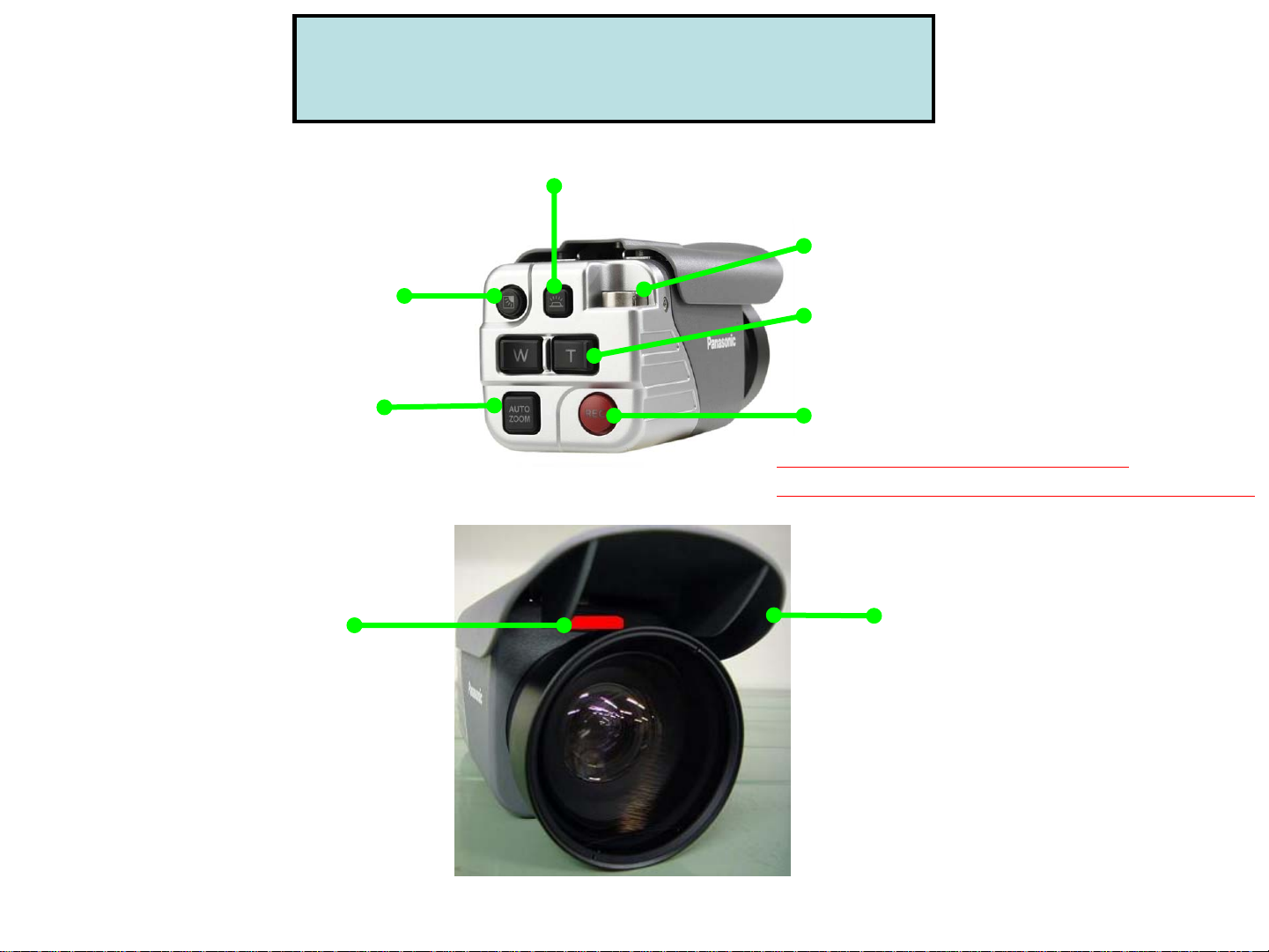
(1) Control Reference Guide
Front Camera (AG-CK10P)
Rear panel LED Control
Backlight compensation
to make it brighter
Auto Zoom
Camera Control
REC LED
Lights up in RED
while recording
Connector for VPU
T(TELE) for Zoom In
W(WIDE) for Zoom Out
REC Start and STOP
*Keep pressing this button for
more than 2 seconds will stop recording.
SUN Shade
Page 4
REC
LED
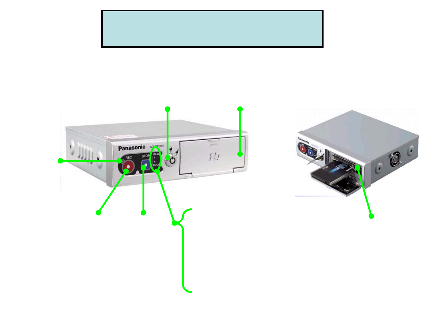
(1) Control Reference Guide
P2 Recorder - VPU (AG-CPD15P)
Key Lock
Locks and unlocks
the P2 Card slot cover
P2 card
slot cover
REC
button
STOP
button
READY lamp
Lights up when
recording is ready
BUSY lamp
Lights up or flashes
while a P2 card is accessed.
P2 card
slot 1, 2
Page 5
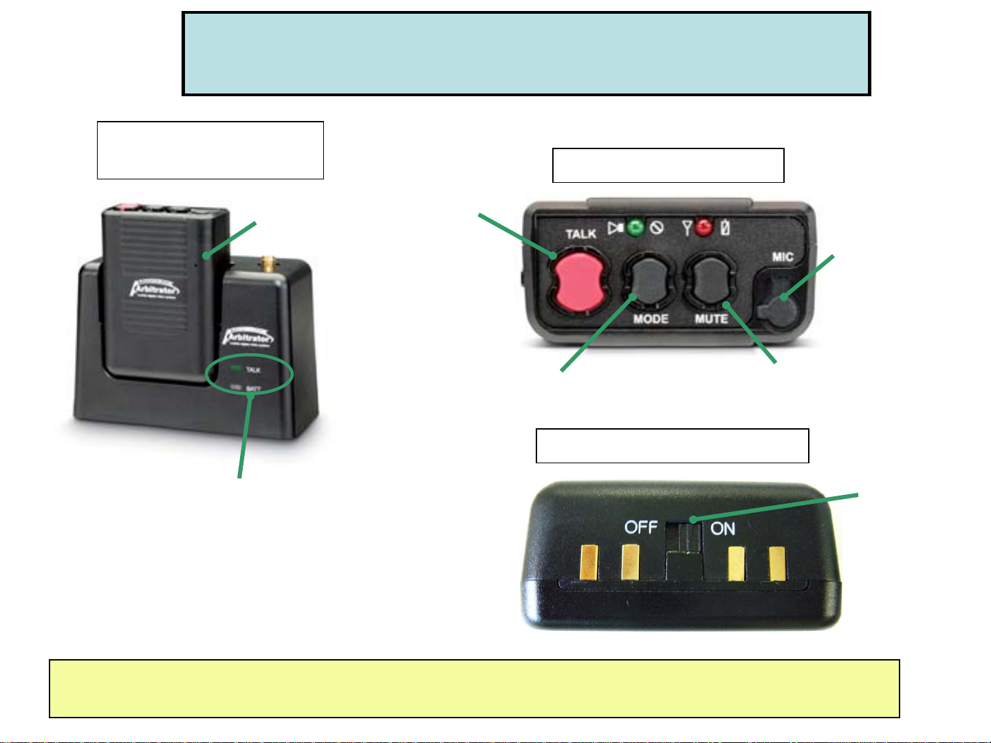
Digital Wireless Microphone TX and RX (CCR24PNA)
Transmitter (TX)
with Receiver (RX)
Built-in Mic
Control Reference Guide
Transmitter (Top View)
TALK Button:
Press for REC
Lavalier Mic
Input
TALK ON : Green LED
BATT : Red-Charging, Green-Fully charged
Please refer to CCR24PNA User Guide for more operation information
MODE Selection Button
Transmitter (Bottom View)
MUTE Button
ON/OFF
Switch
Page 6

Control Reference Guide
(CCR24PNA Vibration / LED Indication)
Mode
Selection
Vibration
and
LED
Vibration Only No Vibration
when Tx is
ready
No Vibration
GREEN On GREEN Blink RED Blink RED On
when Tx is
under
recording
mode
Vibration
(one time only)
Vibration
(one time only)
when Tx is
under
"Low Battery"
status
Vibration
(1 time per second)
Vibration
(1 time per second)
when Tx is
under
"Out Of Range"
status
Vibration
(2 times per 3 seconds)
Vibration
(2 times per 3 seconds)
when Mute is initiated
Vibration
(1 time per 5 seconds)
Tx is not recording:
GREEN On & RED Fast Blink
-------------------------------------------Tx is under recording:
GREEN Blink & RED Fast Blink
Vibration
(1 time per 5 seconds)
None
No Vibration
No LED
1. Default mode when power on.
2. After synchronized, the mode goes back to the last.
3. Please refer to CCR24PNA User Guide for more operation information
Page 7
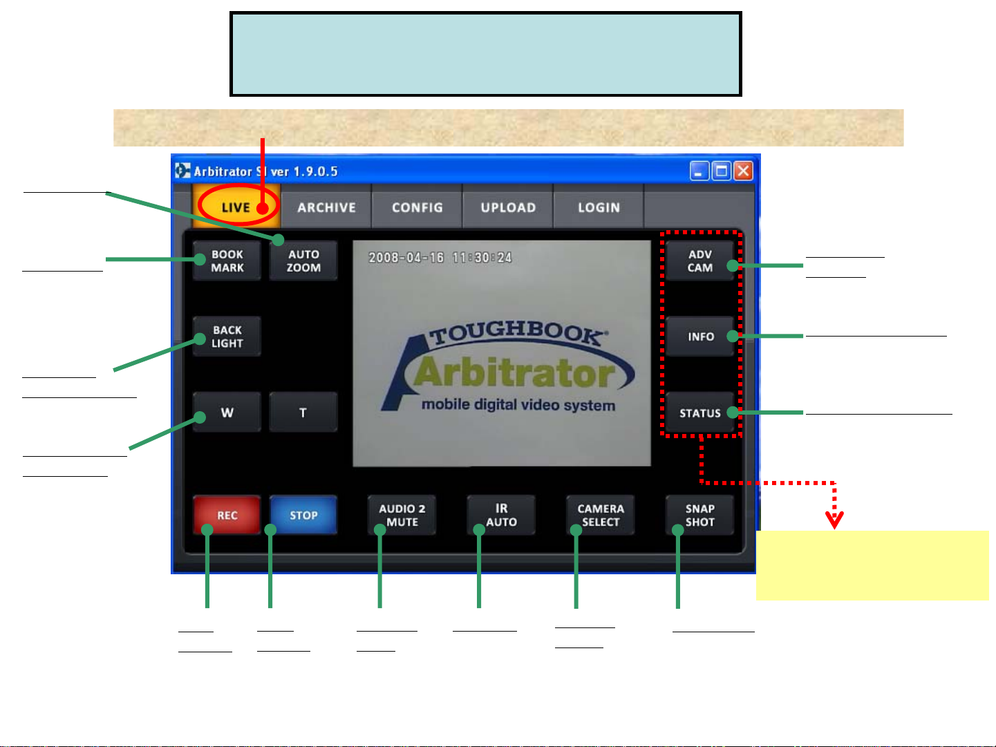
Auto Zoom
(2) SI (Front End Application)
“LIVE” Mode Menu for Officer
Select “LIVE” tab of SI (Front End Application) for Live recording control.
Bookmark
While recording, users can
creating a bookmark by
pressing this button.
Backlight
Compensation
W: Zoom Out
T: Zoom In
REC
Button
Stop
Button
Audio 2
Mute
nd
Mute 2
by pressing on
this button
Audio
IR Mode
(Auto/ON/OFF)
Camera
Select
(Camera1/2))
Advanced
Camera
For camera and audio control
Video Information
For metadata and
officer information
Status Information
For P2 card storage
capacity and system
messages
Pressing these buttons
will expand more menu
on the right side of screen.
Snap Shot
Get a Still image of
whatever the camera
is currently viewing
Page 8
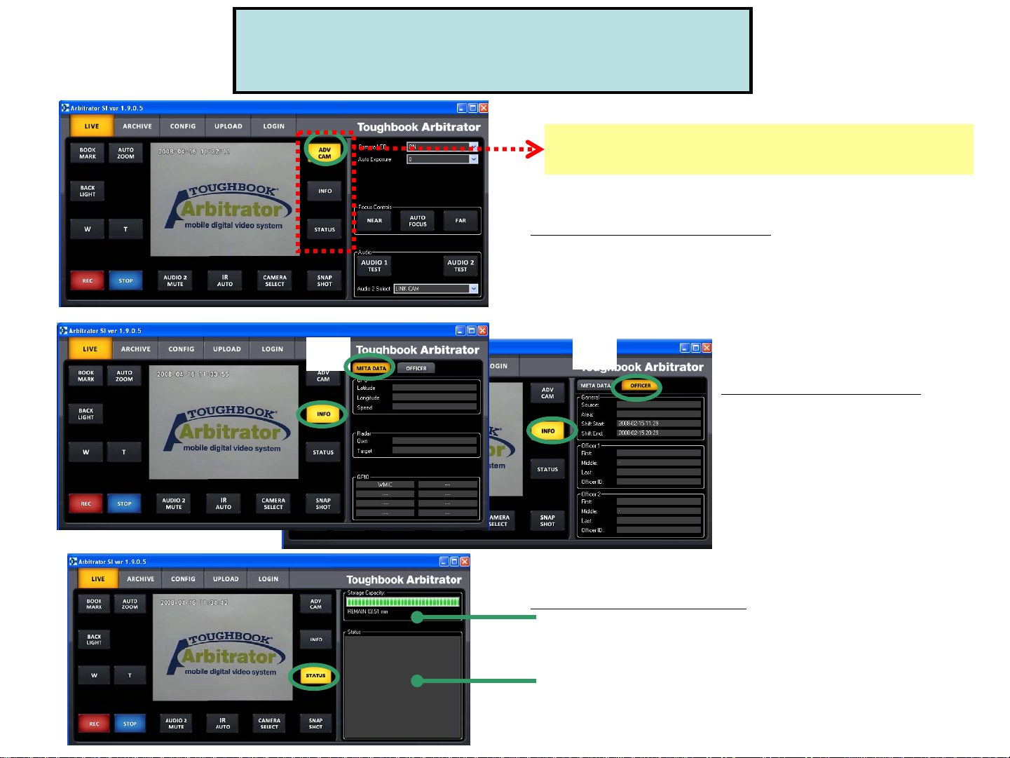
(2) SI (Front End Application)
“LIVE” Mode Menu for Officer
Pressing these buttons (“ADV CAM”, “INFO”,
“STATUS”) will expand the menu on the right side.
ADV CAM (Advanced Camera)
For camera and audio control
(More detail in “Camera Control”)
(1)
(2)
INFO (Video Information)
(1) “META DATA” for GPS, Radar Gun,
GPIO trigger information
(2) “OFFICER” for Source, Area, Shift
time, Officer 1, 2 information
Status (Status Information)
“Storage Capacity”:
Show how much space has been taken on P2 card and how much
time remaining
“Status”:
Any system message including errors, bookmark creation,
snapshot will be displayed.
Page 9
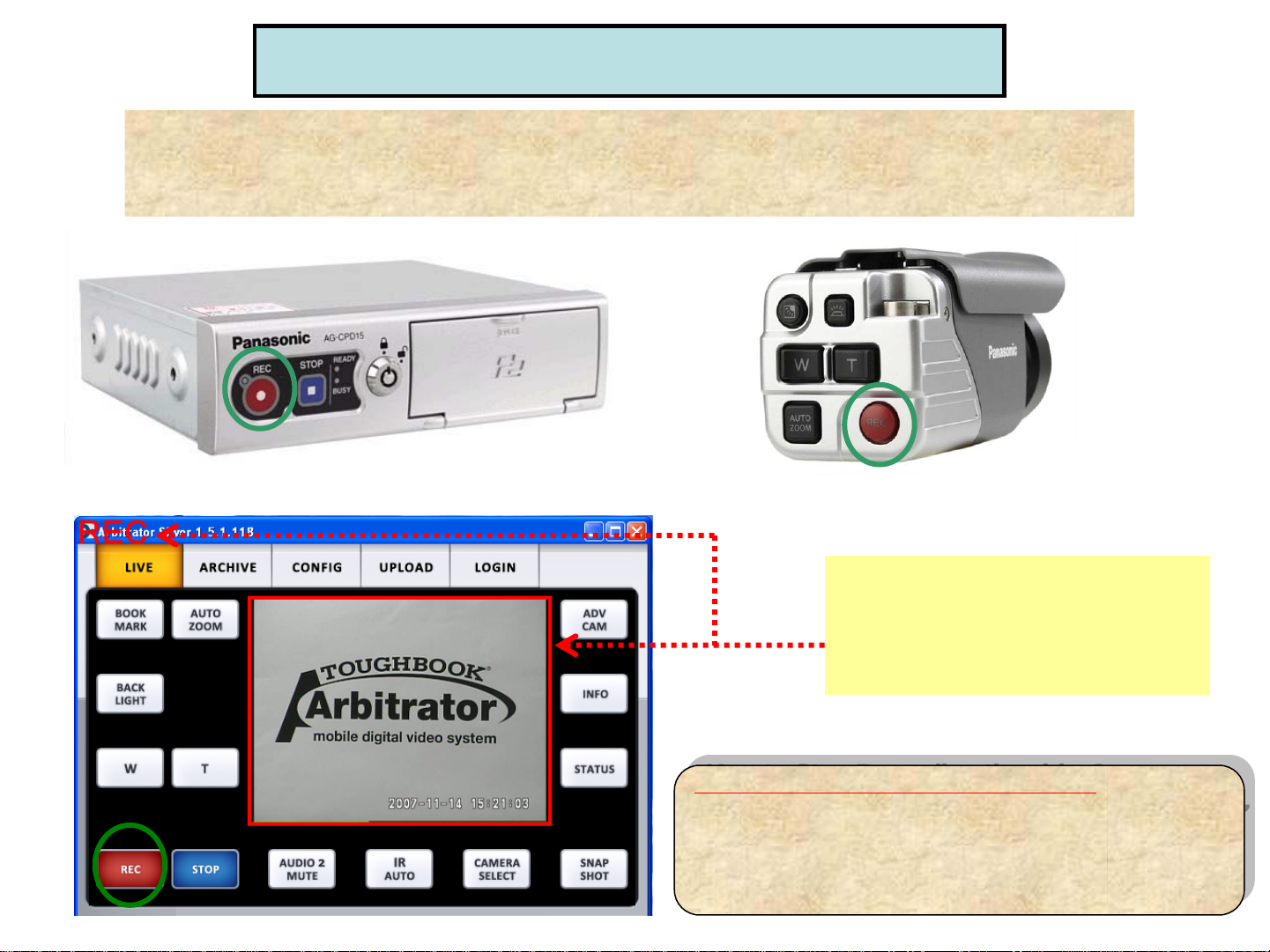
(3) Record the video (“LIVE” Mode)
Press REC button for (1) VPU (P2 Recorder), (2) Camera (Rear Panel),
or (3) “LIVE” tab of SI
*If the trigger is set, VPU will start recording automatically when the trigger is on.
<VPU-P2 Recorder>
<SI-Front End Application>
<Camera>
When recording, users can see
the viewing pane surrounded
in a red highlight and the letter
“REC” in the upper left corner of SI
(Front End Application)
How to Stop Recording the video?
How to Stop Recording the video?
(1) Press STOP button for VPU (P2 Recorder),
(1) Press STOP button for VPU (P2 Recorder),
or “Live” tab of SI.
or “Live” tab of SI.
(2) Keep pressing the Camera REC button
(2) Keep pressing the Camera REC button
for 2 seconds.
for 2 seconds.
Page 10
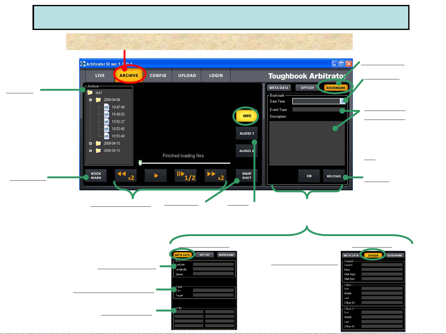
(4) Playback the recorded video (“ARCHIVE” Mode)
Archive
List all the files available
for playback on VPU.
Double clicking the file
will begin playing in
display area
Bookmark
Create a bookmark when
viewing the video by
pressing this button.
Select “ARCHIVE” tab of SI for viewing the recorded video.
Playback Control
Rewind, Pause, Slow and
Fast Forward
Snapshot
Make a still image of
whatever camera is
currently viewing
Audio
By pressing this
button, mute
Audio1 or 2
Pressing “INFO” button will
expand the screen that can be
viewed “META DATA”, “OFFICER”
information and “BOOKMARK”
“Bookmark”
Date/Time
A dropdown list containing
all the bookmark for the
selected file
Event Type/
Description
User can enter free form text
into this field, which will be a
searchable descriptor in Back
End application
OK
Saves the edits or additions
made to Bookmark
Reload
Changes back to the original
format before the recent
changes
GPS Information
Radar Gun Information
GPIO (Trigger)
Show max. 8 triggers
configured for the system
“META DATA”
“OFFICER”
Officer Information
Including Source, Area,
Shift time, Officer 1, 2 as
meta data
Page 11

(5) Camera Control (“LIVE” Mode)
Auto Zoom
Backlight
Compensation
W: Zoom Out
Backlight
Compensation
W: Zoom Out
T: Zoom In
Auto Zoom
T: Zoom In
Snapshot
IR Mode
(Auto, On, Off)
Camera Select
Pressing “ADV CAM” button for camera and audio control will expand a more menu on the right side.
*Initial LPR mode is disabled.
Camera LED
The camera REC LED will light up Red when it is on
Auto Exposure
To set up the brightness of the picture
Focus Control
To configure the sharpness of the image manually
(Near/Far) or automatically
Audio 2 Select
1. “IN CAR” for In car Mic (Mic in)
2. “WMIC” for 2nd Wireless Mic (Audio 2 in)
3. “LINKCAM” to change the Audio 1 or 2
by linking with the camera changes,
*Audio 1 for Wireless Mic 1 (Audio 1 in)
Page 12

(5) Camera Control
for LPR (License Plate Recognition) users (“LIVE” Mode)
This camera control is for LPR (License Plate Recognition) users. In order to use LPR mode,
the administrator needs to set up “Init LPR Mode” as “Enable” in Admin/Camera menu.
[When the recording is being STOPPED in “Live” mode]
1) [LPR Mode] is set to “LPR”
LPR ON
[When the “Live” screen is being RECORDED]
1) [LPR Mode] is set to “LPR”
2) [LPR Mode] is set to “PATROL”
Select “LPR” for LPR ON,
or “PATROL” for LPR OFF
Select “AUTO”, “1/500”
Or “1/1000”
Select “AUTO”, “1/100”,
“1/500” or “1/1000”
Set x1.0 to x22.0
LPR OFF
2) [LPR Mode] is set to “PATROL”
Page 13

(6) Officer Information (“LOGIN” Mode)
[Register by “LOGIN” of SI]
(1) Select “LOGIN” tab and type all the information (Shift, Vehicle, Officer name)
at the beginning of shift.
(2) After completing all the information, press “APPLY” button to register it.
Shift Pattern
Such as DUI, traffic stop etc
according to the officer
Register at the beginning of shift
Start/End
For the start and end time
of the shift
Source
For the vehicle ID
Area
For the general location
of where the mobile unit
resides
Officer 1, 2
For the name of
Officer 1 & 2
OID (Officer ID)
For the ID for Officer 1 & 2
Press this button
after entering all
the information.
Page 14

(7) Upload the recorded file (“UPLOAD” Mode)
For “Manual”* upload wirelessly, select (1) “UPLOAD” tab and press “UPLOAD” button (2), (3).
For “Auto”* upload wirelessly, NO need to go to this “UPLOAD” menu and video will be automatically
uploaded once getting into wireless network range.
*If the administrator sets up “Use Auto Upload” as “False” at “CONFIG” menu, it will be “Manual” upload.
If setting it up as “True”, it will be “Auto” upload.
(1)
(2)
(3)
Page 15

(8) Restore the recorded file (“RESTORE” Mode)
“RESTORE” button will be appeared in the tab of SI when the video file is corrupted*
and cannot be played back.
*The video file corruption will occur when the power to the VPU is lost or turned off while recording,
or when a P2 card is removed while recording
1. Select “RESTORE” tab (1) of SI and press “RESTORE” button (2)
to solve the file corruption and restore the file.
2. Then, “RESTORE” button will be disappeared and the file will be restored.
(1)
(2)
Page 16

Arbitrator (ARB-SI) ver. 1.9
Basic Set up & Operation
[For Administrators]
Page 17

Arbitrator (ARB-SI) Ver.1.9 Basic Set up & Operation
for Administrators
-Contents-
(0) For the Arbitrator version 1.8 Users -How to upgrade to version 1.9?-
(1) -Before Use, Format 16GB P2 Card
-16GB P2 Card Format by Products / Combination with Windows version
(2) “CONFIG” Menu for Administrator
(3) REC/Play Set up
(4) Camera Control: Auto Zoom / IR Set up
(5) OSD (On Screen Display) Set up
(6) UPLOAD
(a) Set up the location of the video that needs to be uploaded
(b)-1. WIRELESS UPLOAD
(b)-2. EXPORT
(b)-3. BURN CD/DVD
(7) Trigger Set up by Administrator - Stop recording by Trigger OFF
(8) Menu (VPU settings) Copy
(9) Auto Power Off Settings
APPENDIX: Setting Files for VPU by USB memory or P2 Card
Page 18

(0) For the Arbitrator version 1.8(or earlier) Users
-How to upgrade to version 1.9?-
If you have the version 1.8 or earlier of Arbitrator, it is necessary to upgrade both SI
(Front End Application) and VPU firmware to the version 1.9 as the following procedure.
[Step 1] Upgrade VPU firmware FIRST by SI version 1.8 or earlier you currently run on PC.
1) Please save the VPU firmware for the version 1.9 to the USB memory or P2 card.
2) Connect that USB memory or P2 card to VPU and by SI menu, go to “Config”, “Operations” and press
“Version up” to upgrade the VPU firmware.
USB Memory*
Save
VPU
Firmware
For Ver. 1.9
*When some USB memory
may not work, please use
the different USB memory.
[Step 2] Then, Upgrade to SI version 1.9
After upgrading the VPU firmware as [Step 1], please uninstall the SI you currently run and install the new SI version 1.9.
REMARK
REC LED
(RED)
READY LED
BUSY LED
(RED)
If upgrading to SI version 1.9 first, you cannot operate the VPU because VPU firmware is still version 1.8 or earlier.
Therefore, in order to upgrade the VPU firmware, please follow the above [Step1] 1). Connect the USB memory or P2 card to VPU.
Leaving the P2 card slot open
(Green)
, follow the procedure in the chart below.
Procedure Duration
1) Keep pressing “STOP” button for 15
sec
2) Updating process for VPU microcomputer 45 ON Flash ON
3) Update complete --- Flash ON Flash
4) Press “STOP” button to restart
5) Updating process for Front microcomputer 150 Flash ON ON
6) Version up complete --- OFF OFF OFF
LED Display
(Sec)
15 OFF OFF OFF
--- Flash Flash Flash
REC READY BUSY
Page 19

(1) Before use, Format 16G P2 card by SI
Formatting 16G P2 card is mandatory at the first time usage.
When modified (copy, delete, move etc) folders in P2 Card, please format the card.
(If you copy the folders/files from 5 slot P2 drive or PC PCMCIA to PC HDD, please format the card.)
The format of 16G P2 card is available by Control Panel, 5 slot P2 drive and PC PCMCIA slot.
Note that 16GB P2 card limit the number of files that can be recorded per below chart.
# of
recording days
62 days 340 files 508 files
# of maximum recording files per day
With Bookmark Without Bookmark
<How to format by SI?>
(a) Insert new 16GB P2 cards to P2 Recorder (VPU)
(b) Go to “Config” by SI menu and select “Operations”.
Press “Format” and then select “Yes”
(c) Press “Format” and select “Yes”.
Then, “Format finished successfully” message
will be appeared when the format is completed.
(Press “Yes” to complete.)
Page 20

(1) 16GB P2 Card Format by Products /
Combination with Windows version
Format by How to format?
SI
(FE Application)
Control Panel By Control Panel Menu, go to “Setup Info”-”Admin”-”File Management”-
PC PCMCIA slot
(Windows)
5 slot P2 Drive
(AJ-PCD20P)
P2 Store
(AJ-PCS060G)
PCMCIA slot (Card Bus) in PC
By SI Menu, go to “Config”-”Operations”-”Format”.
”Format”
Before format, install the P2 driver (from “P2 ICV Filter w/ P2 Drivers” CD included in
Arbitrator kit) to PC. Then, select the removable disc drive in P C that inserted P2 card.
Right click on that drive and select “format”
Before format, install the P2 driver (from “P2 ICV Filter w/ P2 Drivers” CD included in
Arbitrator kit) to PC. Then, select the removable disc drive in P C that inserted P2 card.
Right click on that drive and select “format”
Before format, Install the P2 driver (from “P2 ICV Filter w/ P2 Drivers” CD included in
Arbitrator kit) to PC. Then, press “Format P2C” button on the unit
Vista XP
Pro SP2
Pro SP4 + Hot Fix
2000
Server
2003
Y Y N N
5 slot P2 Drive (AJ-PCD20P)
through USB
5 slot P2 Drive (AJ-PCD20P)
though IEEE1394
P2 Store (AJ-PCS060G)
through USB
Y Y Y N
Y Y N N
Y Y Y N
Page 21

(2) “CONFIG” Menu for Administrator
1. Select “CONFIG” tab of SI and enter the password* to log in.
2. Then, “CONFIG”, “OPERATIONS” and “REGISTRATION” tab will be appeared.
Press “CONFIG” for configuring all the system settings.
*The default password is “pass” and the administrator can
change the password at “Admin Password” in “Config”
Admin Password change settings
Auto Power Off setting to VPU
and/or in car PC
Camera settings
Date & Time settings
File Transfer settings
(Upload/Export/Burn to DVD)
On Screen Display settings
Program recording settings
Record & play mode settings
Day & night view auto switch and
snapshot directory settings
Triggers (8GPIO) settings
Press “APPLY” to apply
the setting changes.
Page 22

Enable or disable output of
recording error status as GPIO9
Enable or disable output of
recording status as GPIO9
Initial Audio 2 setting,
nd
INCAR, 2
Power off time setting after
shutting down the ignition
WMIC or LINK CAM
Initial camera select,
camera 1 or 2
1 fps (frame per sec)
recording
Set Post Rec Time
(0 to 90 seconds)
(3) REC/Play Set up
Start recording
when VPU is turned on
Set Pre Rec Time
(0 to 90 seconds)
Recording will continue up to
1,2,5,10,15,20,30, 60, 90,
or Continue even if
pressing STOP button
Recording mode: F-2Mbps (720x480, 30fps)
F-1Mbps (720x480, 10fps), Q-1Mbps (320x240, 30fps)
Q-512kbps (320x240, 30fps)
Press “APPLY” to apply
the setting changes.
Page 23

1. Select “CONFIG” tab of SI and enter the password* to log in.
2. Then, press “CONFIG” and select “Camera”.
Set the level of camera input gain control
Select “Auto”, “Preset” or “Disable”
“Auto” : Auto focus operates when
the zoom ratio is changed.
“Preset”: Camera is focused at 50ft
when zoom ratio is 3x below.
“Disable”: Focus is locked at 130ft
and auto focus is not available.
Adjust “Auto Zoom Magnification” selecting
from “1,2,3,4,5,7,10,15, or 22” and
“Auto Zoom time” for zoom magnification
retention time from “3,5, or 8” seconds
Select “Auto”, “Off”, “On” or “Last ”
(4) Camera Control
Auto Zoom / IR Set up
Enable or disable LPR
(License Plate Recognition)
When setting “Init IR Mode” as “Auto”,
select IR Level, “Low”, or “High”
and IR Time, “10, 30, 60 or 300”
Adjust “Zoom Limit”, “x22” for optical
or “x220” for digital
Press “APPLY” to apply
the setting changes.
Page 24

(5) OSD (On Screen Display) Set up
1. Select “CONFIG” tab of SI and enter the password to
log in.
2. Then, press “CONFIG” and select “OSD”.
*OSD (On Screen Display) for the Date/Time, Trigger and
Source (Vehicle-ID)/Area set up by Administrator will be
included in the recorded file.
“Source (Vehicle ID) @ Area” will be displayed on screen and
recorded in the recorded file.
“Printable (A to Z)” of the trigger will be displayed on screen
and recorded in the recorded file.
“Source (Vehicle ID) @ Area”
*1. Source (Vehicle ID) and Area need to be set up “LOGIN” menu.
*2. Total 10 letters of “Source @ Area” will be displayed on sc reen.
For example, if Vehicle ID is “1234567” and Area is “California”, it will
be “12345@Cali” appeared on screen.
“Printable (A to Z)” of the trigger
*Printable (A to Z) needs to be set up at “CONFIG” menu-”Triggers”.
Page 25

(6) Upload
(a) Set up the location of the video that needs to be uploaded
1. Select “CONFIG” tab of SI and enter the password* to log in.
2. Then, press “CONFIG” and select “File Transfer” for the
location of video that needs to be uploaded.
Burn to CD/DVD
Select the CD/DVD drive
that is connected
Export to HDD of PC
or the external device
Select the drive that just export
except CD/DVD drive, which
does not need any writer to export
Wireless Upload
Configure the setting checking
with the backend server to be
uploaded
Press “APPLY” to apply
the setting changes.
Page 26

(6) Upload
(b)-1. WIRELESS UPLOAD
1. Select “UPLOAD” tab of SI and press “UPLOAD”
2. If Administrator sets up as Manual upload at “CONFIG”*, officer needs to press
“UPLOAD” button when upload.
(*Menu: “CONFIG”-”File Transfer”-”Upload”-”Use Auto Upload”=“False”)
3. If Administrator sets up as Auto upload at “CONFIG”*, officer does NOT need to
press “UPLOAD” button and video is automatically uploaded.
(*Menu: “CONFIG”-”File Transfer”-”Upload”-”Use Auto Upload”=“True”)
*When setting up as Manual at “Config”,
Need to press this button.
*When setting up as Auto at “Config”,
No need to press this button
Page 27

(6) Upload
(b)-2. EXPORT
1. Select “UPLOAD” tab of SI and press “EXPORT” and enter the
password* to log in.
2. Then, press “EXPORT” button and video will be exported to the
location where administrator set up at “CONFIG”.
(Menu: “CONFIG”-”“File Transfer”-”Export”)
*The default password is “pass” and the administrator can change the
password at “Admin Password” in “Config”
Page 28

(6) Upload
(b)-3. BURN CD/DVD
1. Select “UPLOAD” tab of SI and press “BURN CD/DVD” and enter
the password* to log in.
2. Then, select “Devices” and press “BURN” button and video will
be burned to CD/DVD where administrator set up at “CONFIG”.
(Menu: “CONFIG”-”“File Transfer”-”Burn CD/DVD”)
*The default password is “pass” and the administrator can change the
password at “Admin Password” in “Config”
Page 29

1. Select “CONFIG” tab of SI and enter the password to log in.
2. Then, press “CONFIG” and select “Triggers”.
Trigger On or Off setting
(7) Trigger Set up
Select the Detection from the followings and
choice of detection depends on “Action”:
1. In “REC”, “CAM1REC ”, “CAM2REC” at Action,
Select the detection from “H” , “Level H”, “L”,
“Level L”, “B”.
2. In “CAM1”, “CAM2”, “CAM1LED”, “AUTOZOOM”,
“STOP” selected the detection from “H”, “L”, “B”.
3. In “None”, select the detection from “H”, “L”,
“SPEED” (Trigger 8 only)
Select “Action” from the followings
for the detection of trigger signals
“REC”
“STOP”
“AUTOZOOM”
“CAM1”
“CAM2”
“CAM1REC”
“CAM2REC”
“CAM1LED”: Change ON/OFF of
REC lamp on the Front Camera
(AG-CK10P)
“NONE”: No operation
Assign the characters to be used in the OSD.
*When SPEED is selected at the trigger,
“Printable” becomes ”-” and cannot be modified.
No OSD is displayed.
Press “APPLY” to apply
the setting changes.
Page 30

(7) Trigger Set up - Stop recording by Trigger OFF
REC Continue
Timer Setting
1. Go to “CONFIG””Rec Continue Time
2. Select either of
“Continue” or “1-90”
Trigger
Setting
Go to “CONFIG”-”Triggers”
Select either of “H Level (HL)”,
“L Level (LL)” for Detection
to stop recording by Trigger OFF
Stop Recording
by Trigger OFF
Yes Yes (Level H or Level L) No
ex. Level H
No No (H, L, No, or B) No (“Continue”) “STOP” button is pressed.
[Remark] 1. If setting up more than 2 triggers as Level Signal, start recording when the 1
stop recording when all triggers set up as Level Signal are turned off.
2. Minimum recording time is 1 minute when setting up the trigger as Level Signal.
Detection
(Level Signal Setting)
STOP REC STOP
REC Continue Time
(Timer Setting)
(“Continue”)
Yes
(“1 – 90”)
Yes (“1 – 90”) 1) “STOP” button is pressed.
Stop Recording Priority
1) “STOP” button is pressed.
2) Trigger OFF
1) “STOP” button is pressed.
2) Trigger OFF
3) “REC Continue Time”
2) “REC Continue Time”
st
trigger is turned on and
Page 31

(8) Menu (VPU settings) Copy
[Step 1] Get a setting configuration file from the VPU which settings need to be copied to other VPUs.
(1) Plug an USB memory* to the VPU which settings need to be copied to other VPUs.
(2) Select “CONFIG” tab of SI and enter the password to log in.
(3) Press “Operation” and “MENU COPY” button if you agree to copy menu settings to the USB memory.
*This action creates a setting configuration file in the USB memory. Please use the USB memory to get the setting configuration file
because even if inserting a P2 card, it cannot be created in the P2 card.
When some USB memory may not get the file, please use the different USB memory.
(2), (3)
(1)
[Step 2] Copy the settings to the 2
Plug the USB memory stored a setting configuration file at [Step 1] to the 2
nd
VPU.
nd
VPU.
Leaving the P2 card slot open, follow the procedure in the chart below.
*Menu/VPU setting, Administrator/Officer information, Even t Type (Bookmark) and Radar setting will be copied, but the following data will NOT be copied
Operating Time for AG-CPD15/Fan/CAM1/AG-RCP30, LCD Lighting Time, BIOS creation date, Last Errors, Version for AG-CPD15/AG-RCP30/Microcontroller
Duration
(Sec)
10 OFF (Flash) (Flash)
--- Flash ON Flash
REC READY BUSY
LED Display
Either LED will flash
REC LED
(RED)
BUSY LED
Procedure
READY LED
(Green)
1) Keep pressing “REC” button for 10
sec till “Ready” or “Busy” lamp starts to flash
2) Loading a configuration file 20 to 50 ON Flash ON
3) Press “STOP” button when “Ready”
lamp lights ( “REC”/”Busy” lamp starts to flash.)
(RED)
4) Reboot and the copy completed. OFF OFF OFF
:
Page 32

(9) Auto Power Off Settings
“Auto Power Off” function enables to shut d o wn the SI (Application), In car PC and VPU* automatically
after turning off the car engine and uploading the files.
(1) Set up “Auto” as Power Off Timer under “Config” and “Rec/Play”.
(2) Go to “Auto Power Off” under “Config” and select which actions to take after uploading.
*In this setting VPU is always turned off after turning off the car engine and uploading the files.
Select the Application (SI),
(2)
(1) Set “Auto” at PowerOff Time
Laptop PC or SI & Laptop to
take action
Action to take after turning off
the car engine and uploading
Time (30, 60, 90 or 120 sec)
to take action after turning
off the car engine and
uploading
After turning off the engine
and uploading the files
During this screen, you can change the action to choose.
Page 33

APPENDIX: Setting Files for VPU by USB memory or P2 Card
The chart below indicates whether USB memory or P2 card can be
used for each file to be loaded to VPU.
USB Memory P2 Card
VPU Firmware Upgrade File*1 YES YES
Please format P2 card by PC and
save the VPU firmware before
upgrading it.
Officer/Administrator
YES NO
Information Text File*2
Event Type Text File*2 YES NO
Menu Copy Setting
YES NO
Configuration File
(to get from the original VPU)
*1: Please DO NOT save any other files or folders except VPU Firmware Upgrade File into USB memory or P2 card.
*2: Please make sure to save these text files under “WIDKEY” folder to USB memory.
If saving the files under some other folder to USB memory, no information will be loaded to the VPU.
Even If saving some other folders together with “WIDKEY” folder (including these text files) to USB memory,
these information will be loaded to VPU.
 Loading...