

Page 1

Arbitrator-CP ver.1.9
Basic Operation
[For Officers]
Page 2

Arbitrator-CP Basic Operation for Officers
-Contents-
(1) Control Reference Guide
(2-a) Control Panel Menu for Officer (for non LPR users)
(2-b) Camera Menu for LPR (License Plate Recognition)
(3) Record the video (Live Mode)
(4) Playback the recorded video (Archive Mode)
(5) Camera Control: (a) Zoom (b) Auto Zoom (c) IR Mode
(6) Officer Information - Register at the beginning of shift & delete at
the end of shift
Front Camera (AG-CK10P)
P2 Recorder-VPU (AG-CPD15P)
Control Panel (AG-RCP30P)
Control Panel - User Friendly Design
Digital Wireless Microphone (TDSS-900-PNA)
Page 3

(1) Control Reference Guide
Front Camera (AG-CK10P)
Rear panel LED Control
Backlight compensation
to make it brighter
Auto Zoom
Camera Control
REC LED
Lights up in RED
while recording
Connector for VPU
T(TELE) for Zoom In
W(WIDE) for Zoom Out
REC Start and STOP
*Keep pressing this button for
more than 2 seconds will stop recording.
SUN Shade
Page 4
REC
LED
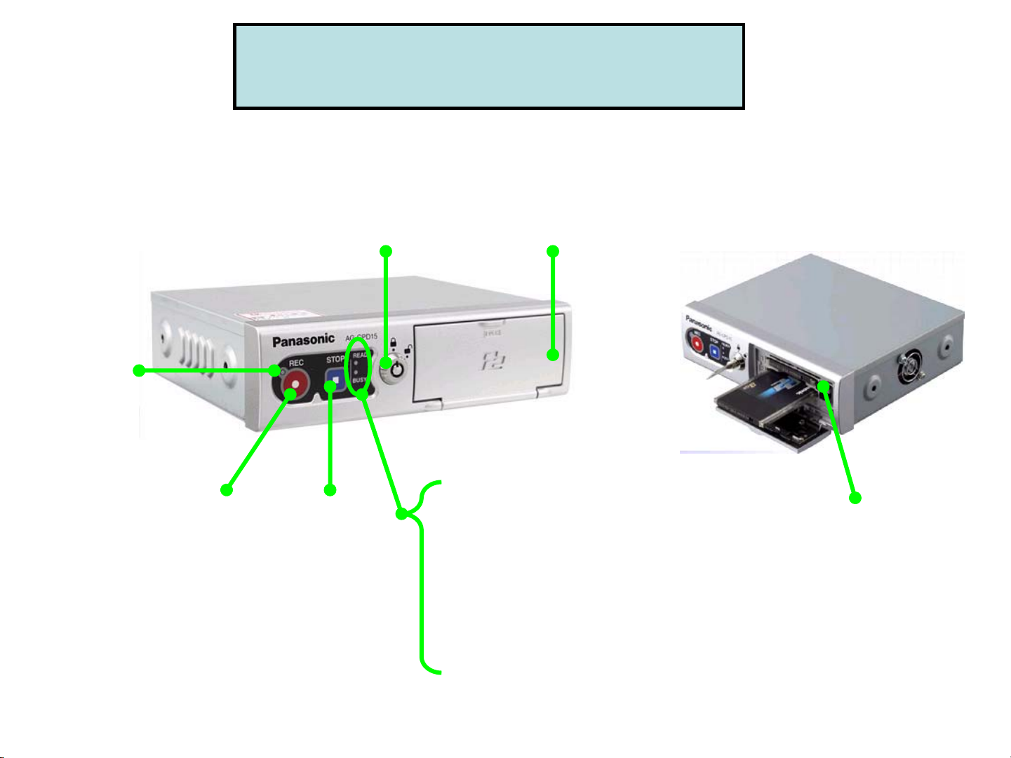
(1) Control Reference Guide
P2 Recorder - VPU (AG-CPD15P)
Key Lock
Locks and unlocks
the P2 Card slot cover
P2 card
slot cover
REC
button
STOP
button
READY lamp
Lights up when
recording is ready
BUSY lamp
Lights up or flashes
while a P2 card is accessed.
P2 card
slot 1, 2
Page 5
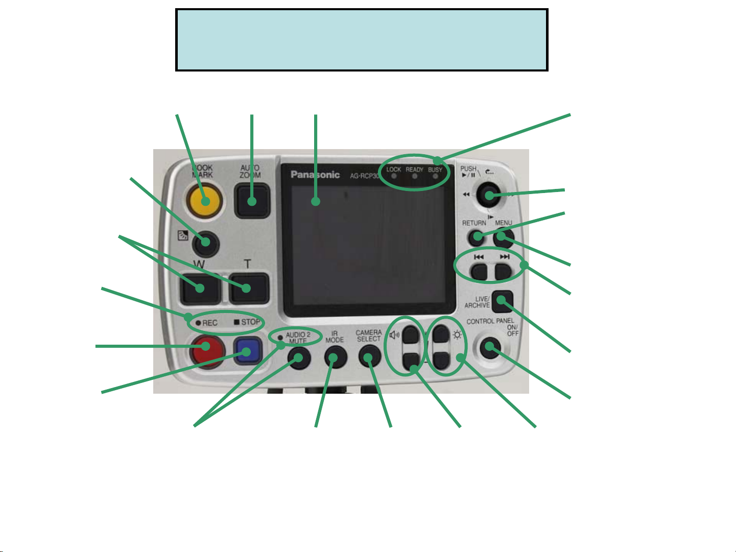
(1) Control Reference Guide
Control Panel (AG-RCP30P)
Backlight
Compensation
T: Zoom In
W: Zoom Out
REC/STOP
Lamp
REC
Button
Book
Mark
Auto
Zoom
LCD
Screen
1) Lock Lamp
Lock except “REC”, “Menu”,
“Control Panel ON/OFF”,
“Return” Button while lights on
2) Ready Lamp
3) Busy Lamp
Cursor Button
Return
To go back to previous
menu or setting
Menu
Skip
(Back/Forward)
Live/Archive
Switching Button
STOP
Button
Audio 2 Mute
Button/Lamp
Mute Audio 2 and lamp lights
on by pushing this button.
No recording while muting
(lights on)
IR Mode
(Auto/ON/OFF)
Camera
Select
(Camera1/2))
Volume
Control
Control Panel
ON/OFF
Brightness
Control
Page 6
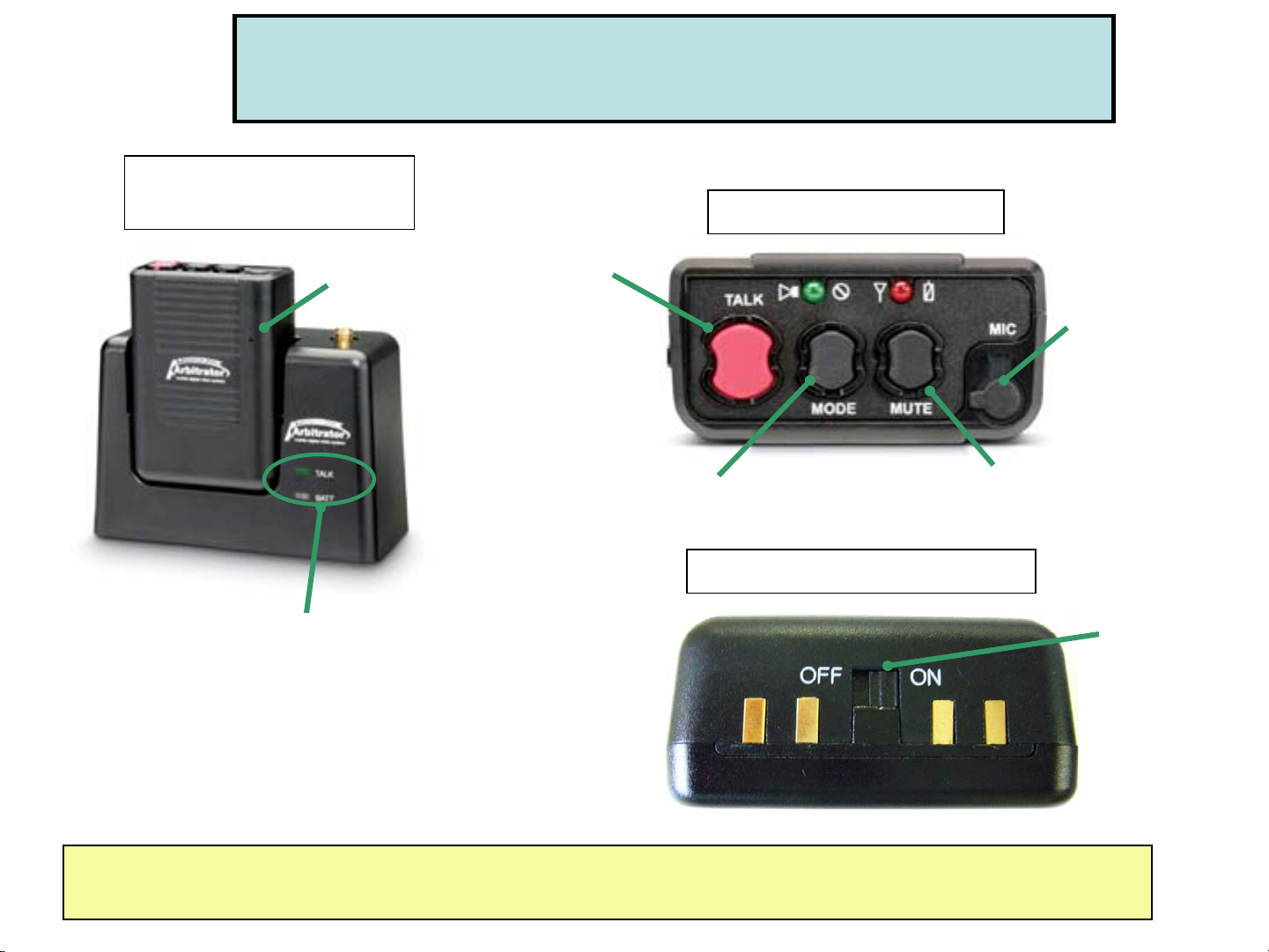
Digital Wireless Microphone TX and RX (CCR24PNA)
Transmitter (TX)
with Receiver (RX)
Built-in Mic
Control Reference Guide
Transmitter (Top View)
TALK Button:
Press for REC
Lavalier Mic
Input
TALK ON : Green LED
BATT : Red-Charging, Green-Fully charged
Please refer to CCR24PNA User Guide for more operation information
MODE Selection Button
Transmitter (Bottom View)
MUTE Button
ON/OFF
Switch
Page 7

Control Reference Guide
(CCR24PNA Vibration / LED Indication)
Mode
Selection
Vibration
and
LED
Vibration Only No Vibration
when Tx is
ready
No Vibration
GREEN On GREEN Blink RED Blink RED On
when Tx is
under
recording
mode
Vibration
(one time only)
Vibration
(one time only)
when Tx is
under
"Low Battery"
status
Vibration
(1 time per second)
Vibration
(1 time per second)
when Tx is
under
"Out Of Range"
status
Vibration
(2 times per 3 seconds)
Vibration
(2 times per 3 seconds)
when Mute is initiated
Vibration
(1 time per 5 seconds)
Tx is not recording:
GREEN On & RED Fast Blink
-------------------------------------------Tx is under recording:
GREEN Blink & RED Fast Blink
Vibration
(1 time per 5 seconds)
None
No Vibration
No LED
1. Default mode when power on.
2. After synchronized, the mode goes back to the last.
3. Please refer to CCR24PNA User Guide for more operation information
Page 8

(2-a) Control Panel Menu for Officer
[Top Menu]
[Restore]
When appeared in
Control Panel OSD, execute
“Restore”
[Setup/Info]
[Camera] For users who do not use LPR (Licens e Plate Recognition mode)
(“Init LPR Mode” in Admin set up is “Dis able” as a factory default.)
*For LPR users, please go to ”Camera Menu for LPR” for details
Re-Auto Focusing
Adjust manual focus
Adjust image brightness
[Audio]
1. “IN CAR” for In car Mic (Mic in)
2. “WMIC” for 2nd Wireless Mic (Audio 2 in)
3. “LINKCAM” to change the Audio 1 or 2
by linking with the camera changes,
*Audio 1 for Wireless Mic 1 (Audio 1 in)
Check Audio
[Archive]
Playback the recorded video
On Screen Type for Control Panel
“Auto”, “SIMPLE”, “DETAILS” or “OFF”
Camera LED (Camera Tally Light),
for “ON” or “OFF”
Page 9

(2-b) Camera Menu for LPR (License Plate Recognition)
In order to use LPR (License Plate Recognition) mode, the Administrator needs to set up
“Init LPR Mode” as “Enable” in Admin/Camera menu.
*If setting up “Init LPR Mode” as “Disable”, there will be no “LPR Mode”, “LPR/Patrol Shutter Speed”, “LPR/Patrol Zoom” on screen as shown
below. (Just “Auto Focus”, “Manual Focus” or “AE” can be selectable and changed in “Camera” menu.)
[Top Menu] while recording is
being stopped in the live screen
[Top Menu] while the live screen
is being recorded
[Camera]
1) [LPR Mode] is set to “LPR”
LPR ON LPR OFF
[Camera]
1) [LPR Mode] is set to “LPR”
2) [LPR Mode] is set to “PATROL”
“LPR” for LPR ON
“Patrol” for LPR OFF
Select “Auto”,
“1/500”, or “1/1000”
Select “Auto”, “1/100”
“1/500”, or “1/1000”
Set x1.0 to x22.0
2) [LPR Mode] is set to “PATROL”
Page 10

(3) Record the video (Live Mode)
Press REC button for (1) Control Panel, (2) Camera (Rear Panel), or (3) VPU (P2 Recorder)
*If the trigger is set, VPU will start recording automatically when the trigger is on.
<Control Panel>
<VPU-P2 Recorder>
<Camera>
Page 11

(4) Playback the recorded video (Archive Mode)
(a) Press “Live/Archive” button of Control Panel to playback the video.
(Playback starts from the location where playback was last made. Or if the recording was started or stopped
prior to pressing “Live/Archive” button, playback starts from the beginning of the file.)
Or
(b) Press “Menu” of Control Panel and go to “Archive”.
(b)
[Live mode]
(a)
[Archive mode]
Page 12
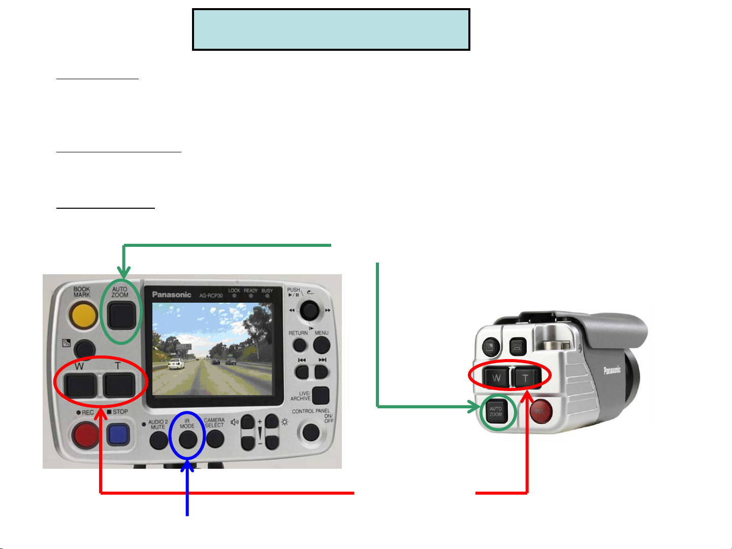
(5) Camera Control
(a) Zoom
“W”: Zoom Out
“T”: Zoom In
(b) Auto Zoom
Press “Auto Zoom” button of Control Panel or Camera.
(c) IR Mode
Press “IR Mode” button switching to IR “Auto”, “On”, “Off”
Auto Zoom
IR Mode
W: Zoom Out
T: Zoom In
Page 13
(6) Officer Information
Register at the beginning of shift & delete at the end of shift
(A) Register the Officers information (At the beginning of shift)
(1) “Auto”: Plug USB memory (saved the officer information) to VPU.
(2) “Manual”: Plug USB memory to VPU and press “Load” button.
If 2 officers need to be loaded, plug 2 different USB memories to VPU.
(3) “List”: Press “Select” button in “Officer” by Control Panel menu.
(B) Delete the Officer information (At the end of shift)
“Manual”, “List”: Press “Delete” button in “Officer” by Control Panel menu.
[Top Menu]
-while REC stopped-
[Manual]
[List]
Register
Officers
Delete
Officers
Page 14

Arbitrator-CP ver.1.9
Basic Set up & Operation
[For Administrators]
Page 15

Arbitrator-CP Basic Set up & Operation for Administrator
-Contents-
(1) -Before Use, Format 16GB P2 Card
-16GB P2 Card Format by Products / Combination with Windows version
(2) Control Panel (AG-RCP30P) -User Friendly Design(3) Control Panel Menu for Administrator
(4) REC/Play Set up by Administrator
(5) Camera Control - Auto Zoom / IR Set up by Administrator
(6) Control Panel Key Lock
(7) On Screen Type set up by Officer / OSD set up by Administrator
(a) Live Mode On Screen Type
(b) Archive Mode On Screen Type
(8) Trigger
(a) Set up by Administrator
(b) Stop recording by Trigger OFF
(9) Menu (VPU Setting) Copy
(10) Event Type for Bookmark
(a) Create an Event Type text and register it to VPU
(b) How to Add / Delete the Bookmark?
(11) Officer/Admin Information Set up
(12) VPU Firmware Upgrade
Page 16

(1) Before use, Format 16G P2 card
Formatting 16G P2 card is mandatory at the first time usage.
When modified (copy, delete, move etc) folders in P2 Card, please format the card.
(If you copy the folders/files from 5 slot P2 drive or PC PCMCIA to PC HDD, please format the card.)
The format of 16G P2 card is available by Control Panel, 5 slot P2 drive and PC PCMCIA slot.
Note that 16GB P2 card limit the number of files that can be recorded per below chart.
# of
recording days
62 days 340 files 508 files
# of maximum recording files per day
With Bookmark Without Bookmark
<How to format 16GB P2 card by Control Panel?>
• Insert new 16GB P2 cards to P2 Recorder (VPU)
• By Control Panel Menu, go to “Setup/Info”, “Admin (page 2/2)”, “File Management” and select “Format”
• Press “Format” when “Format all P2 cards!!!” message is appeared.
Then, you will see “All cards are formatted” message when the format is completed.
[File Management]
[Setup/Info]
[Top Menu]
[Admin] Page 2/2
Page 17

(1) 16GB P2 Card Format by Products /
Combination with Windows version
Format by How to format?
SI
(FE Application)
Control Panel By Control Panel Menu, go to “Setup Info”-”Admin”-”File Management”-
PC PCMCIA slot
(Windows)
5 slot P2 Drive
(AJ-PCD20P)
P2 Store
(AJ-PCS060G)
PCMCIA slot (Card Bus) in PC
By SI Menu, go to “Config”-”Operations”-”Format”.
”Format”
Before format, install the P2 driver (from “P2 ICV Filter w/ P2 Drivers” CD included in
Arbitrator kit) to PC. Then, select the removable disc drive in P C that inserted P2 card.
Right click on that drive and select “format”
Before format, install the P2 driver (from “P2 ICV Filter w/ P2 Drivers” CD included in
Arbitrator kit) to PC. Then, select the removable disc drive in P C that inserted P2 card.
Right click on that drive and select “format”
Before format, Install the P2 driver (from “P2 ICV Filter w/ P2 Drivers” CD included in
Arbitrator kit) to PC. Then, press “Format P2C” button on the unit
Vista XP
Pro SP2
Pro SP4 + Hot Fix*
2000
Server
2003
Y Y N N
5 slot P2 Drive (AJ-PCD20P)
through USB
5 slot P2 Drive (AJ-PCD20P)
though IEEE1394
P2 Store (AJ-PCS060G)
through USB
*For the users who need Win2000 Pro SP4+Hot Fix, please contact 1-800-LAPTOP5 (1-800-527-8675) to obtain it.
Y Y Y N
Y Y N N
Y Y Y N
Page 18

Live Control
Mode Buttons
(2) Control Panel (AG-RCP30P)
- User Friendly Design -
Admin/Archive
Control
Mode Buttons
1. High Priority Buttons for Live Control Mode on the left side for easy access
High Priority Buttons REC, STOP, Zoom in/out, Bookmark Auto Zoom, Backlight compensation
2. The Same REC/STOP Button Size as that of VPU (P2 Recorder) for easy
recognition
3. Large Button Size and Space
between buttons for Users
Page 19

(3) Control Panel Menu for Administrator
[Top Menu]
[Admin] Page 1/2
Record/Play mode settings
Date and Time settings
Officer Registration
Trigger (8GPIO) settings
[Setup/Info]
[Admin] Page 2/2
Export or Delete files
Format files
On Screen Display settings
to appear on screen and
include in recording files
Camera settings
Management mode
For Officer Registration
(Auto, Manual, List)
Page 20

(4) REC/Play Set up by Administrator
Power off time setting after shutting down the ignition
Initial camera setting, camera 1 or 2
[Admin] Page 1/2
From Control Panel Top Menu
--”Setup info”—”Admin”
Initial Audio 2 setting, INCAR or 2
Start recording when VPU is turned on
Setting: Off Fixed
1 fps (frame per sec) recording
Recording mode: F-2Mbps (720x480, 30fps)
F-1Mbps (720x480, 10fps), Q-1Mbps (320x240, 30fps)
Q-512kbps (320x240, 30fps)
Recording will continue up to 1,2,5,10,15,20,30, 60, 90,
or Continue even if pressing STOP bu tton
Set Pre Rec and Post Rec Time (0 to 90 seconds)
Set rule of file name, world tim e (WT) or local time (LT)
Select On Screen Display, “Simple”, “Details”, “Last”
or “Off”
Enable or disable output of recording statu s as GPIO9
Enable or disable output of recording Error status as GPIO9
Select the initial audio output upon power on.
(Off, 1, 2, Both, Last)
Select “Single” (normal playback, one file at a time) or
“Relay” (multiple files playback)
Playback jumps to the trigger or bookmark position,
whichever found earlier
nd
WMIC or LINK CAM
Move to the beginning of a file during playback
Page 21

(5) Camera Control-Auto Zoom / IR Set up by Administrator
[Admin] Page 1/2
From Control Panel Top Menu
--”Setup info”—”Admin”
Adjust “Zoom Limit”, “x22” for optical
or “x220” for digital
1. Adjust “Auto Zoom Magnification”
selecting from “1,2,3,4,5,7,10,15, or 22”
2. Adjust “Auto Zoom” Time for zoom magnification
retention time from “3,5, or 8” seconds
*Factory Initial setting:
“Zoom Limit” = “x22”
“Auto Zoom Magnification” = “10”
“Auto Zoom Time” = “3” seconds.
Select “Auto”, “Off”, “On” or “Last ”
When setting “Init IR Mode” as “Auto”,
select IR Level, “Low”, or “High”
and IR Time, “10, 30, 60 or 300”
Select “Auto”, “Pres et ”, or “Di s ab l e ”.
“Auto”: Set to auto focus when zoom ratio is changed.
“Preset”: When the soom is 3x or below, the camera
is focused at about 15m (50ft).
“Disable”: Focus is locked at a distance of about 40m
(130ft) and auto focus is disabled.
Enable or disable LPR (Lice nse Plate Recognition)
Page 22

(6) Control Panel Key Lock
All buttons except buttons in circle
“REC”
“Cursor Button” “Menu” “Return”
“Control Panel On/Off”,
“REC” on both VPU and Camera
will be locked.
Control Panel Key Lock Set up by Administrator and Officer
[Key Lock by Admin]
From Control Panel Top Menu
--”Setup info”—”Admin”
[Key Lock by Officer]
From Control Panel Top Menu
--”Setup info”—”Officer”
Select “Operation Key Lock”,
“On” or “Off”.
**When locked by Administrator,
the key cannot be unlocked
by Officer (from “Officer” Set up).
Page 23

(7) On Screen Type set up by Officer
/ OSD set up by Administrator
[Top Menu]
[Setup/Info]
[Admin] Page 1/2
On Screen Type set up by Officer,
“AUTO”, “SIMPLE”, “DETAILS” or “OFF”
*1. See more details on “Live mode on screen type” and “Archive
mode on screen type”.
*2. On Screen Type will NOT be recorded in the recording file.
“Printable (A to Z)” of the
trigger will be recorded
in the recorded file when
turning on the trigger.
OSD (On Screen Display) for the date/time,
trigger and V-ID/Area set up by Administrator
will be included in the recorded file.
**If On Screen Type “DETAILS” is set up, this OSD will be hidden.
“Vehicle ID @ Area” will be recorded in the recorded file when
turning on “V-ID/Area”.
*1. Vehicle ID and Area need to be included in the Officer registration text file.
*2. The first 5 letters for Vehicle ID and the first 4 letters for Area will be
appeared on screen. For example, if Vehicle ID is “1234567” and Area is
“California”, it will be “12345@Cali” appeared on screen.
Page 24

(7) On Screen Type set up by Officer /OSD set up by Administrator
(a) Live Mode On Screen Type
[SIMPLE]
(8)
(9)
(10)
[DETAILS]
(2)
(5)
(2)
(1)
(3)
(4)
(6)
(7)
(1) Remaining P2 card recording time
(2) Mode indication ( Pause, Record)
(3) Status Display
PON: Power On Recording “ON”
CARD FULL: No space on P2 car d
CARD PROTECT: The write-protect swit ch of P2 card is set to protect
VUP CARD: Recording is not possible du e to P2 card intended for
version upgrade
UNFORMATTED: P2 card is not formatted
REFORMAT: P2 card needs to b e reformatted
ILLEGAL CARD: An unusable card is inserted in VPU
NO CARD: No P2 card is inserted in VPU
RUNDOWN: P2 card is closed to the end of its service life
(4) Remaining P2 Card capacity bar
(5) “Restore” appears only when there is a file that needs to be restored
(1)
(6) Mark Position Bookmark position
(3)
(7) VPU set up Status
(4)
C1: Camera 1 selected C2: Camera 2 selected
IR: Camera IR mode is “ON” IRA: Camera IR mode is “OFF”
BL: Camera backlight is “ON” TAL: Camera lamp is “ON”
LOCK: Control Panel Key Lock is “ON”
(11)
(12)
(5) (6)
*If setting on screen type “AUTO” and (1), (2) or (3)
is changed, “SIMPLE” on screen type will be
appeared on screen for 3 to 5 seconds.
(8) Speed (MPH/KPH): OWN-own vehicle speed, TGT-target vehicle speed
*Target vehicle speed depends on the type of radar gun that is connected
(9) Location information (latitude)
(7)
(1 0) Location information (longitude)
(1 1) Date/Time
(1 2) Trigger input status: GPIO 1 to 8 are displayed in ord er from the left.
The letters assigned by “Printable” appear when the “Detection” occurs
Page 25

(7) On Screen Type set up by Officer /OSD set up by Administrator
(a) Archive Mode On Screen Type
[SIMPLE]
(1)
(2)
(5)
(3)
(1) Playback filename (Local time at start of recording)
(4)
(2) Mode indication ( Playback, Pause, FF RW Slow)
(3) Playback Speed and Status Display
<Playback Speed> x1/10, x1/2, x4, x20, x200
<Status Display>
READ ERROR: An error occurred while reading
META ERROR: No associated meta information file exists.
PLAY ERROR: A decoder malfunction occ urred
(6)
(4) Playback location
(7)
(5) “Restore” appears only when there is a file that needs to be restored
[DETAILS]
(8)
(9)
(10)
(11)
(12)
*If setting on screen type “AUTO” and (2) or (3)
is changed, “SIMPLE” on screen type will be
appeared on screen for 3 to 5 seconds.
(2)
(5) (6)
(6) Mark Position Bookmark position Trigger position
File beginning
(1)
(7) Sound output setting: A1-Audio 1 A2-Audio 2
(3)
(4)
(8) Speed (MPH/KPH): OWN-own vehicle speed, TGT-target vehicle speed
*Target vehicle speed depends on the type of radar gun that is connected
(9) Location information (latitude)
(1 0) Location information (longitude)
(1 1) Date/Time
(1 2) Trigger input status: GPIO 1 to 8 are displayed in ord er from the left.
(7)
The letters assigned by “Printable” appear only when the “Detection” occurs.
Page 26

(8) Trigger
(a) Set up by Administrator
(1) Go to “Trigger” in “Admin” menu by Control Panel.
(2) Select “Action” which you need when detecting the trigger signal (Trigger 1 to 8).
Select the Detection from the followings and
choice of detection dep ends on “Action”:
Trigger On or Off setting
Select “Action” from the followings
for the detection of trigger signals
“REC”
“STOP”
“AUTOZOOM”
“CAM1”
“CAM2”
“CAM1REC”
“CAM2REC”
“CAM1LED”: Change ON/OFF of
REC lamp on the Front Camera
(AG-CK10P)
“NONE”: No operation
1. In “REC”, “CAM1REC”, “CAM2R E C” at A ction,
Select the detection from “H”, “Level H”, “L”, “Level L”, “B”.
2. In “CAM1”, “CAM2”, “CAM1LED”, “AUTOZO OM ”, “STOP ”,
Select the detection from “H”, “L”, “B”.
3. In “None”, select the detection from “H”, “L”,
“SPEED” (Trigger 8 only)
Remark:
“SPEED” via speed pulse at Detection detects only in
Trigger 8 since the detection cir cuit for the only Trigger 8
is designed for speed pulse.
Assign the characters to be used in the OSD display.
*When SPEED is selected at the trigger, “Printable”
becomes ”-” and cannot be modified. No OSD is displayed.
Page 27

[Admin]
From Control Panel Top Menu
--”Setup info”—”Admin”
(8) Trigger
(b) Stop recording by Trigger OFF
REC Continue
Timer Setting
Trigger
Setting
Select either of
“Continue” or “1-90”
Select either of “Level H”, “Level L”
to stop recording by Trigger OFF
Stop Recording
by Trigger OFF
Yes Yes
No No
[Remark] 1. If setting up more than 2 triggers as Level Signal, start recording when the 1
stop recording when all triggers set up as Level Signal are turned off.
2. Minimum recording time is 1 minute when setting up the trigger as Level Signal.
Detection
(Level Signal Setting)
(Level H or Level L)
ex. Level H
STOP REC STOP
(H, L, No, or B)
REC Continue Time
(Timer Setting)
No
(“Continue”)
Yes
(“1 – 90”)
No
(“Continue”)
Yes
(“1 – 90”)
Stop Recording Priority
1) “STOP” button is pressed.
2) Trigger OFF
1) “STOP” button is pressed.
2) Trigger OFF
3) “REC Continue Time”
“STOP” button is pressed.
1) “STOP” button is pressed.
2) “REC Continue Time”
st
trigger is turned on and
Page 28

(9) Menu (VPU settings) Copy
[Step 1] Get a setting configuration file from the VPU which settings need to
be copied to other VPUs.
(1) Plug an USB memory* to the VPU which settings need to be copied to other VPUs.
(2) Go to “Service”-“Operations” in “Admin” menu by Control Panel and select “Menu Copy”.
(3) Press “Copy” button if you agree to copy menu settings to the USB memory.
*This action creates a setting configuration file in the USB memory. Please use the USB memory to get the setting configuration file
because even if inserting a P2 card instead to the VPU, it cannot be created in the P2 card. When some USB memory may not
get the file, please use the different USB memory.
[Step 2] Copy the settings to the 2
Plug the USB memory stored a setting configuration file at [Step 1] to the 2
nd
VPU.
nd
VPU.
Leaving the P2 card slot open, follow the procedure in the chart below.
*Menu/VPU setting, Administrator/Officer information, Even t Type (Bookmark) and Radar setting will be copied, but the following data will NOT be copied
Operating Time for AG-CPD15/Fan/CAM1/AG-RCP30, LCD Lighting Time, BIOS creation date, Last Errors, Version for AG-CPD15/AG-RCP30/Microcontroller
Duration
(Sec)
10 OFF (Flash) (Flash)
--- Flash ON Flash
REC READY BUSY
LED Display
Either LED will flash
REC LED
(RED)
BUSY LED
Procedure
READY LED
(Green)
1) Keep pressing “REC” button for 10
sec till “Ready” or “Busy” lamp starts to flash
2) Loading a configuration file 20 to 50 ON Flash ON
3) Press “STOP” button when “Ready”
lamp lights ( “REC”/”Busy” lamp starts to flash.)
(RED)
4) Reboot and the copy completed. OFF OFF OFF
:
Page 29

(10) Event Type for Bookmark
(a) Create an Event Type text and register it to VPU
[STEP 1: Create the Event Type text file (“evtype.txt”) and save it to the USB memory.]
Plug an USB
memory to PC
Create “WIDKEY”
under root directory
by PC.
Create the event
type te xt file
“evtype.txt”
under “WIDKEY”
<Event Type text file ex ample>
USB Memory*
*When some USB memory may not work,
please use the different USB memory.
[STEP 2: Register the Event Type for the Bookmark to VPU.]
(a) Plug the USB memory stored the event type file “evtype.txt” to VPU.
(b) Go to “Registration” in “Admin” menu by Control Panel and select “Load Event Type”.
Plug the USB
memory stored
“evtype.txt”
to VPU
Up to 99 letters
for each type,
Max 10 event type
in the “evtype.txt”
EvType1=Criminal Arrest
EvType2=Traffic Stop
EvType3=DUI
●
●
●
EvType10=Drinking Check
REMARK: How to delete the Event Type?
Create the Blank Event Type text file (saved as “evtype.text”) and save it to the USB memory as STEP 1.
Then, please follow the same procedure as like STEP 2 to load the Blank Event Type text file.
Page 30

(10) Event Type for Bookmark
(b) How to Add / Delete the Bookmark?
LIVE mode
(during recording)
Event Type
Loaded to VPU
Add the
bookmark
bookmark
YES
Press “Bookmark” button.
will appear on screen.
N/ADelete the
Press “Bookmark” button.
will appear and select the event type.
Press “Bookmark” button while appears.
“DEL” to delete the bookmark.
<How to Add the Bookmark?>
In case the event types are loaded
(1) Press the bookmark button at Archive mode*.
(2) Event type pop up will appea r and select an event type
by “◄►” button.
(3) Press the “Bookmark”, “Return” or “Menu” button
to confirm the entry.
(1)
ARCHIVE mode
(during playback)
YES
will appear and select the
Press “Bookmark” button.
will appear.
Press “Bookmark” button
while appears.
NONO
<How to Delete the Bookmark?>
In case the event types are loaded,
(1) Press the Bookmark button while the Event type pop up appears.
(2) Select “DEL” in the Event Type pop up by “◄►” button.
(3) Press the “Bookmark”, “Return” or “Menu” button to confirm the entry.
(1)
(2)
(2)
In case no event types are loaded
(1) Press the “Bookmark” button at Live or Archive mode.
(2) A Bookmark icon will appear on screen.
In case no event types are loaded,
Press the “Bookmark” button when a bookmark icon
appears at Archive mode during playback, pause or slow playback.
*Event type will appear on screen only at Archive mode.
At live mode, the bookmark icon appears on screen
by pressing “Bookmark” button
Page 31

(11) Officer/Admin Information Set up
-Contents-
1. Admin Set up (1) Creating Text Files and Saving in USB memory
2. Admin Set up (2) Sample Text Files for Officer/Admin
APPENDIX: Officer/Admin Information Text File Comparison
3. Admin Set up (3) How to register Officer/Admin information?
4. Admin Set up (4) How to log in “Admin” menu?
5. Admin Set up (5) How to delete Admin/Officer information?
6. Officer Set up (1) How to register Officers info at the beginning of shift?
APPENDIX: How to register Officers?
7. Officer Set up (2) How to delete Officers info at the end of shift?
APPENDIX: Setting Files for VPU by USB memory or P2 Card
Page 32

-Officer/Admin Information Set up by Control Panel-
Admin Set up (1) Creating Text Files and Saving in USB memory
USB
Memory*
Plug USB
memory
to PC
Create “WIDKEY”
under root directory
By PC
Create the following text files under
“WIDKEY” directory:
(1) Officer Data File
(2) Officer Registration File
(3) Administrator Registration File
(4) Event Type File
(see “Event Type for Bookmark”)
(1) Officer Data File:
“wid*****.txt “
(Up to 8 characters
for file name,
1 text file per officer,
Max 2 text files)
(3) Administrator
Registration File
“wadmin.txt”
(Max. 10 Administrators)
*When some USB memory may not work,
please use the different USB memory.
(2) Officer Registration File “wofficer.txt”
(Max. 500 Officers)
**Necessary only when using “Officer List” mode
(4) Event Type File “evtype.txt” For Bookmark
(See “Event Type for Bookmark)
(Up to 99 characters for each type,
Max 10 event types in the “evtype.txt”)
Page 33

-Officer/Admin Information Set up by Control Panel-
Admin Set up (2) Sample Text Files for Officer/Admin
Please make sure to save these text files under WIDKEY folder to USB memory.
(1) Officer Data File: “wid*****.txt “
*Up to 8 characters for file name,
1 text file per officer, Max 2 text files
Ex. File “widtest1.txt”
# Sponge Bob
FirstName=Sponge
MiddleName=
LastName=Bob
ID=ICV12345
Password=Pana1
SDate=2007-09-13
STime=9:00
Edate=2007-09-13
ETime=17:00
Shift=DUI
Area=District1
Source=54321
Ex. File “widtest2.txt”
# Patrick Star
FirstName=Patrick
MiddleName=
LastName=Star
ID=ICV54321
Password=Pana2
SDate=2007-09-14
STime=08:15
Edate=2007-09-14
ETime=18:00
Shift=Traffic
Area=District2
Source=10000
(2) Officer Registration File:
“wofficer.txt”
*Max 500 officers in 1 text file
*Necessary only when using “Officer List” mode
*Shift time, shift, area and source will NOT
registered.
# Ichiro Suzuki
FirstName=Ichiro
MiddleName=
LastName=Suzuki
ID=ICV51
Border=-----------------------------------# David Ortiz
FirstName=David
MiddleName=
LastName=Ortiz
ID=ICV34
Border=-----------------------------------# Derek Jeter
FirstName=Derek
LastName=Jeter
ID=ICV2
Border=-----------------------------------# Joe Mauer
FirstName=Joe
LastName=Mauer
ID=ICV7
be
(3) Administrator Registration
File: “wadmin.txt”
*Max 10 Administrator in 1 text file
# James Bond
FirstName=James
Middle Name=
LastName=Bond
ID=ICV007
Password=007
Border=---------------------# Jimmy Harris
FirstName=Jimmy
Middle Name=
LastName=Harris
ID=ICV010
Password=010
4) Event Type File “evtype.txt” For
Bookmark
(See “Event Type for Bookmark)
*Up to 99 characters for each type,
Max 10 event types in the “evtype.txt”
EvType1=Criminal Arrest
EvType2=Traffic Stop
EvType3=DUI
Page 34

APPENDIX: Officer/Admin Information Text File Comparison
-Data of text files for Officer/Admin-
Remark/Limitation
Data to loaded
to VPU
First Name 50
Middle Name 1
Last Name 50
ID 50
Password 12
Max
Characters
Officer Data File
“wid*****.txt”
1) Up to 8 characters
for file name
2) 1 text file per officer,
Max 2 text files
Y Y Y
Y Y Y
Y Y Y
Y Y Y
Y N Y
Officer Registration File
“wofficer.txt”
1) Max 500 officers in 1 text file
2) Necessary only when using
“Officer List” mode
3) Shift time, shift, area and
source will NOT be registered.
Administrator Registration
File: “wadmin.txt”
1) Max 10 Administrator
in 1 text file
2) Shift time, shift, area and
source will NOT be registered
SDate 10
STime 5
EDate 10
ETime 5
Shift 10
Area 10
Source 50
Y: Data that can be loaded to VPU N: Data that can NOT be loaded to VPU
Y N N
Y N N
Y N N
Y N N
Y N N
Y N N
Y N N
Page 35

-Officer/Admin Information Set up by Control Panel-
Admin Set up (3) How to register Officer/Admin information
(A) Before registering the Officers, Administrator needs to set “Management Mode” in “Admin ” menu
such as “Auto”, “Manual” or “List” for Officer registration mode. (See “Officer Set up (1)”)
[Admin]
[Top Menu]
[Setup/Info]
[Management Mode]
(A)
(B)
Select “Auto”, “Manual” or “List”
(See “Officer Set up (1)”
(A)
(B) How to register Officer/Admin Information to VPU by Control Panel?
1. Plug USB memory saved Officer Registration File (“wofficer.txt”)
and Admin Registration File** (wadmin.txt) to VPU
2. Go to “Registration” in “Admin” menu
Load Admin:
Load Max 10 Administrators from a USB
memory saved “Administrato r Registration
File” to VPU
List Admin:
View Max 10 Administrator name & ID that
had already registered in VPU
(B)
[Registration]
Load Officer:
Load Max 500 Officers from a USB memory
saved “Officer Registrati on File” to VPU
List Officer:
View Max 500 Officer name and ID that
had already registered in VPU.
Page 36

-Officer/Admin Information Set up by Control Panel-
Admin Set up (4) How to Log in “Admin” menu?
How to Log in “Setup/Admin” menu by administrator?
(1) Create Officer Data File (wid*****.txt) that is the same Admin information registered in VPU
(2) Save the Officer Data File to USB memory and plug it to VPU to log in “Setup/Admin” menu
NOTE1: If many officer data files are existing in USB memory, VPU will detect the first one in ascending order.
NOTE2: If wrong USB memory plug to VPU, the error message will appear.
“wadmin.txt”
registered in VPU
# James Bond
FirstName=James
Middle Name=
LastName=Bond
ID=ICV007
Password=007
[Top Menu]
“widtest3.txt”
(same info as “wadmin.txt”)
r
e
g
i
s
t
e
r
e
d
[Setup/Info]
# James Bond
FirstName=James
Middle Name=
LastName=Bond
ID=ICV007
Password=007
SDate=2007-10-01
STime=9:00
Edate=2007-10-01
ETime=17:00
(different info from
“wadmin.txt”)
# Sean Connery
FirstName=Sean
Middle Name=
LastName=Connery
ID=ICV777
Password=1234
SDate=2007-10-01
STime=9:00
Edate=2007-10-01
ETime=17:00
s
a
v
e
Right USB memory*
Plug to VPU
Wrong USB memory*
Plug to VPU
e
v
sa
*When some USB memory may not work,
please use the different USB memory.
[Admin]
[Error Message]
Page 37

-Officer/Admin Information Set up by Control Panel-
Admin Set up (5) How to delete Admin/Officer information?
How to delete Admin information when Admin information had registered in VPU?
(1) Log in “Admin” menu followed by Admin Set up (4)
(2) Create a blank Admin Registration File (wadmin.txt) and save it to USB memory. Then, plug USB
memory to VPU and select “Load Admin” in Admin menu (see Admin Set up (4))
Or
ig
# James Bond
FirstName=James
Middle Name=
LastName=Bond
ID=ICV007
Password=007
*When some USB memory may not work,
please use the different USB memory.
r
e
g
i
s
t
e
in
r
Blank Admin
Registration File:
a
l
l
y
e
d
“wadmin.txt”
#
FirstName=
Middle Name=
LastName=
ID=
Password=
S
a
v
e
Plug into VPU for delete
Blank Officer
Data File:
“wofficer.txt”
#
FirstName=
Middle Name=
LastName=
ID=
S
e
v
a
USB memory*
How to delete Officer information when Admin information had registered in VPU?
(1) Log in “Admin” menu followed by Admin Set up (4)
(2) Create a blank Officer Data File (wofficer.txt) and save it to USB memory. Then, plug USB
memory to VPU and select “Load Officer” in Admin menu (see Admin Set up (4))
Page 38

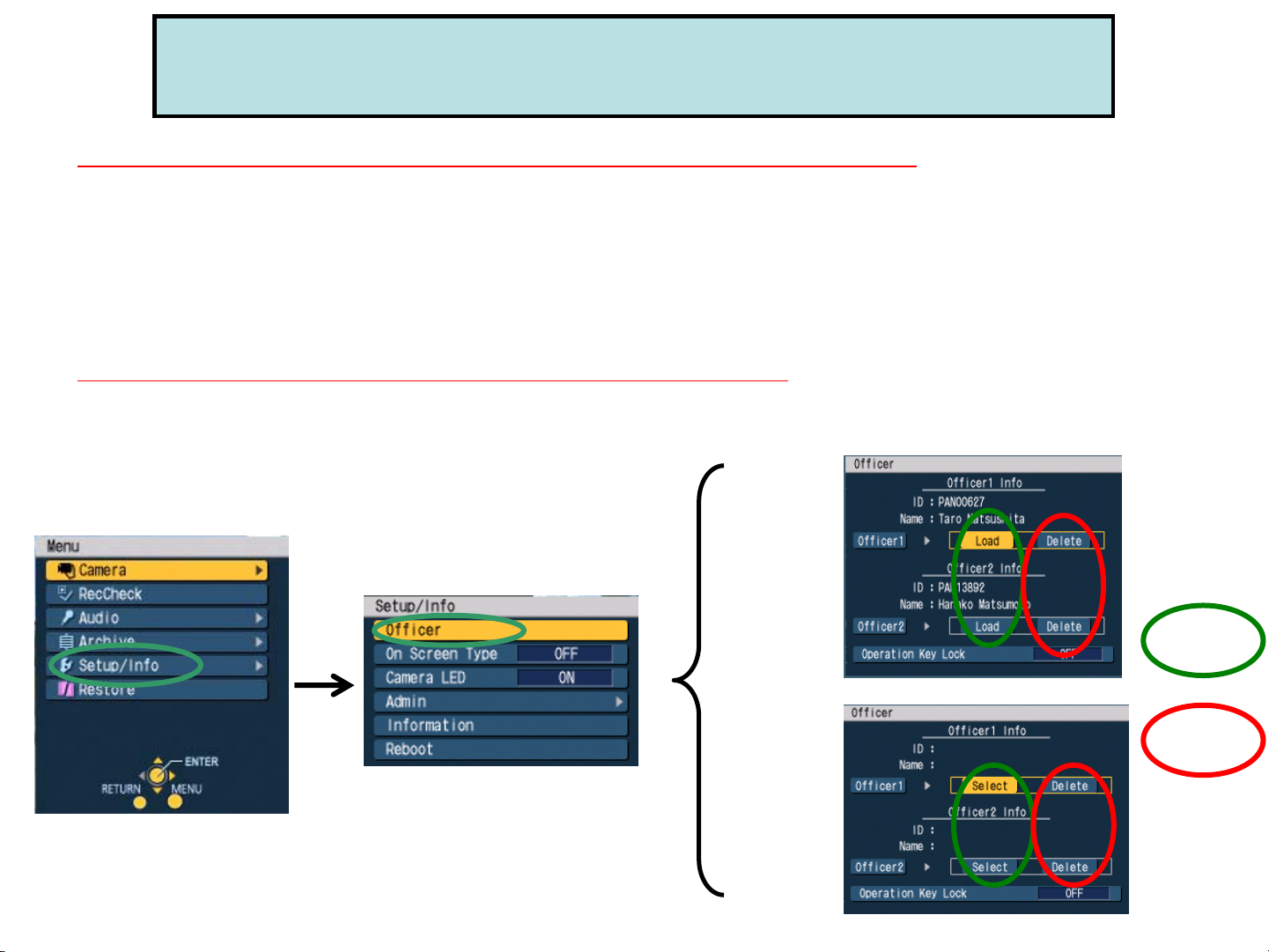
-Officer/Admin Information Set up by Control Panel-
Officer Set up (1) How to register Officers info at the beginning of shift?
How to register the Officers information at the beginning of the shift?
(1) Plug USB memory saved the Officer information as the file “wid*****.txt”
(2) Go to “Officer” by Control Panel menu and Officer Data will be registered according to the
“Management Mode” set up by Administrator
NOTE1: ”Management Mode” in “Admin” menu needs to be set as “Auto”, “Manual” or “List” by Administrator
(See “Admin Set up (2)”)
NOTE2: “Auto” will be loaded the first 2 files in ascending order if there exists some files in USB memory.
“Manual” will be loaded the first file only in ascending order. If there are 2 officers to load, it’s necessary to have 2 USB
memories.
Officer Info Registration according to “Management Mode”
[Auto] [Manual]
[Top Menu]
[Setup/Info]
“AUTO” mode is to loads the
max 2 Officer Data Files from
a USB memory automatically
[List]
“LIST” mode is to list and select
the officer data that had already
registered in VPU.
“MANUAL” mode is to be used
when Officer 1 and 2 data needs to
be loaded by 2 different USB
memories
Page 39

-Officer/Admin Information Set up by Control Panel-
APPENDIX: How to register Officers?
The below chart is the cases of registering Officers by the “wid*****.txt” file
according to the “Management Mode” in “Admin” menu.
(“Top Menu”-”Setup Info”-”Admin”-”Management Mode”)
“wid*****.txt” file to save to the USB memory
Up to 2 different
“wid*****.txt” files
Management Mode
Auto
Manual
List
Up to 2 Officers will
be loaded.
1 Officer of the first file only in ascending order will be
loaded. (In order to load 2 Officers, prepare 2 USB
memories and save 1 file each.)
N/A
Officers that had already loaded by the “wofficer.txt” file can be selected by this
mode.
More than 3 different
“wid*****.txt” files
2 Officers of the first 2 files in
ascending order will be loaded.
More than 2 Officers
information in 1
“wid*****.txt” file
The last Officer
(information) in the file
will be loaded.
Page 40

-Officer/Admin Information Set up by Control Panel-
Officer Set up (2) How to delete Officers info at the end of shift?
How to delete Officers information at the end of the shift?
Go to “Officer” by Control Panel menu.
• If either “Manual” or “List” in “Management Mode” is set by Administrator, delete it at “Officer”.
• If “Auto” is set, please overwrite the next one or two officers by USB memor y saved Officer Data
File (wid*****.txt)
Officer Info Delete according to “Management Mode”
[Manual] [List]
[Top Menu]
[Setup/Info]
*When some USB memory may not work,
please use the different USB memory.
(1)
(2)
Due to No delete for Officer Info at “Auto” in “Management Mode”,
please overwrite the next Officers information by Officer Data File
[Auto]
“wid*****.txt”
# James Bond
FirstName=James
Middle Name=
LastName=Bond
ID=ICV007
Password=007
SDate=2007-10-01
STime=9:00
Edate=2007-10-01
ETime=17:00
Shift=Traffic
Area=District 5
Source=5555
s
a
v
e
Plug in
Page 41

APPENDIX: Setting Files for VPU by USB memory or P2 Card
The chart below indicates whether USB memory or P2 card can be
used for each file to be loaded to VPU.
USB Memory P2 Card
VPU Firmware Upgrade File*1 YES YES
Please format P2 card by PC and
save the VPU firmware before
upgrading it.
Officer/Administrator
YES NO
Information Text File*2
Event Type Text File*2 YES NO
Menu Copy Setting
YES NO
Configuration File
(to get from the original VPU)
*1: Please DO NOT save any other files or folders except VPU Firmware Upgrade File into USB memory or P2 card.
*2: Please make sure to save these text files under “WIDKEY” folder to USB memory.
If saving the files under some other folder to USB memory, no information will be loaded to the VPU.
Even If saving some other folders together with “WIDKEY” folder (including these text files) to USB memory,
these information will be loaded to VPU.
Page 42

(12) VPU Firmware Upgrade
-How to upgrade the firmware version 1.9 from version 1.8 or earlier?-
1) Please save the VPU firmware for the version 1.9 to the USB memory* or P2 card by PC.
Please DO NOT save any other files or folders except VPU Firmware Upgrade File into USB memory.
When using P2 card, please format P2 card by PC and save the VPU firmware only before upgrading it.
2) Connect that USB memory or P2 card to VPU. By Control Panel menu, go to “Admin”-“Service”
-“Operations” and select “Version up” to press “Yes”.
3) After version up is completed and the system is rebooting, the VPU goes back to “Live” mode.
You can check if the firmware is upgraded in this same m e nu.
USB Memory*
Save
VPU
Firmware
For Ver. 1.9
*When some USB memory may not work,
please use the different USB memory.
[Top Menu] [Setup/Info] [Admin 2/2]
[Service] [Operations] [Version up]
 Loading...