

Panasonic Aquarea Tank Duo GH 200, Aquarea Tank Duo GH 300, Aquarea Tank Duo GH 200 Pre-plumbed, Aquarea Tank Duo GH 300 Pre-plumbed Installation Manual
Unvented cylinders specifically designed to work with a heat pump
Design, Installation & Servicing Instructions
Models covered in this manual
Aquarea Duo 200-300 litres
Aquarea Duo (Pre-plumbed) 200-300 litres

These instructions should be read in conjunction with the installation/servicing
instructions issued by the manufacturer of the heat source being used.
Any installation must be in accordance with the relevant requirements of the Building
Regulations, I.E.E. Wiring Regulations and the Water Fitting Regulations (England and
Wales) or Water Byelaws (Scotland). It should be read in accordance with the relevant
recommendations of the following:
BS EN 12828, BS EN 12831, BS EN 14336;
BS 5440:1; BS 5440:2; CP 331:3
BS EN 806-1 to 5, BS EN 8558:2011 and BS 7593:2006
Aquarea is covered by Section G3 of the Building Regulations (England and Wales)
Technical Standard P3 (Scotland) and Building Regulation P5 (Northern Ireland),
technical guidance documents G and L and SEI Heating and Domestic Hot Water
Systems for Dwellings - Achieving compliance with Part L 2008 (Republic of Ireland).
Compliance can be achieved via a Competent Person Self Certication Scheme or
noticaton of installation to the Local Authority Building Control Department.
It must be installed by a competent person as dened by the relevant regulations.
Manufacturers notes must NOT be taken as over-riding statutory obligations.
This appliance is not intended for use by persons (including children) with reduced
physical, sensory or mental capabilities, or lack of experience and knowledge unless
they have been given supervision or instruction concerning use of the appliance by
a person responsible for their safety. Children should be supervised at all times to
ensure they do not play with the appliance.
This information is provided to assist generally in the selection of equipment.
Responsibility for selection and specication of our equipment must however remain
that of our customer and any experts or consultants concerned with the installation(s).
ISSUE 2: JUNE 2016
Section Page
DESIGN
Description 3
Technical Information 4
System Design 6
INSTALLATION
Installation 8
Commissioning 17
USER INSTRUCTIONS 18
SERVICING AND MAINTENANCE
Servicing and Maintenance 19
Fault Finding 21
Short Parts List 22
APPENDIX
Appendix A 23
Appendix B 24
Terms & Conditions 25
Please note: that we do not therefore accept any responsibility for matters of
design selection or specication, for the eectiveness of an installation or system
containing one of our products unless specically requested to do so in writing.
All goods are sold subject to our Conditions of Sale which are set out at the rear of this
specication. In the interest of continuously improving the Aquarea range, Aquarea
reserve the right to modify the product without notice, and in these circumstances
this booklet, which is accurate at the time of printing, should be disregarded. An
updated set of Instructions will be produced and supplied with new appliances and
will be made available for other appliances on request.
Aquarea is produced under an ISO 9001:2008 Quality Management System
approved by BSI.
Benchmark places responsibilities on both manufacturers and installers. The purpose is to
ensure that customers are provided with the correct equipment for their needs, that it is
installed, commissioned and serviced in accordance with the manufacturers instructions
by competent persons and that it meets the requirements of the appropriate Building
Regulations. The Benchmark Checklist can be used to demonstrate compliance with
Building Regulations and should be provided to the customer for future reference.
Installers are required to carry out installation, commissioning and servicing work
in accordance with the Benchmark Code of Practice which is available from the
Heating and Hot Water Industry Council who manage and promote the Scheme.
Visit www.centralheating.co.uk for more information.
Benchmark Checklist 26
Benchmark Service Record 27
Page 2

DESIGN
Product Details
Maximum inlet pressure to
Pressure reducing valve 12 bar
Operating pressure (PRV setting) 3 bar
Expansion vessel charge pressure 3 bar
Expansion relief valve setting 4.5 bar
Opening pressure of P & T Relief Valve 6 bar
Opening temperature of P & T Relief Valve 92-95°C
Energy cut-out thermostat setting 82°C
Max. working pressure - Primary heat exchanger (Indirect models) 6 bar
Immersion heater rating 3kW, 240V AC
All cylinders are manufactured in accordance with the requirements of BS EN 12897
The tundish must be positioned so that it is visible to the occupant and is away from
electrical devices.
Components supplied with Aquarea:
• Cold water inlet PRV combination valve/expansion relief
• Pressure and temperature relief valve
• Control thermostat
• Energy cut-out thermostat
• Energy cut-out motorised valve (indirects only)
• Tundish
• 3kW Immersion heater including control and cut out thermostats
• Expansion vessel/mounting bracket/exible hose
• Technical/user product literature
In any situation where the volume of heated pipework (eg. secondary circulation
pipes or manifold pipework for multiple units) exceeds 10 litres, then an
additional expansion vessel must be tted to accommodate the extra expansion
volume.
Handling Before Installation
Aquarea must be handled with care and stored the correct way up in a dry place.
Any manual handling/lifting operations will need to comply with the requirements
of the Manual Handling Operations Regulations issued by the H.S.E. The appliance
can be moved using a sack truck on the rear face although care should be taken and
the route should be even. In apartment buildings containing a number of storeys we
would recommend that the appliances are moved vertically in a mechanical lift. If it is
proposed to use a crane, expert advice should be obtained regarding the need for
slings, lifting beams etc.
A specic manual handling assessment is shown in Appendix B at the rear of this
manual.
The Environment
This product has been manufactured using many recyclable materials, including the
approved HCFC/CFC free polyurethane foam insulation. At the end of its useful life, it
should be disposed of at a Local Authority Recycling Centre, to maximise the products
full environmental benets.
Maintenance
Modifications should not be made to this
product. Replacement parts, including
immersion heaters, should be purchased
from Aquarea, or agents approved by them.
Unvented hot water storage vessels need
regular routine checks, and these are detailed
below. It is for this reason that this manual must
always be left with the Aquarea.
It is essential that these checks be carried out
at the time of boiler maintenance by a qualied
installer:
1. Manually open the relief valves in turn, and
check that water is discharged from the
valves and runs freely through the tundish
and out at the discharge point. Ensure that
the valves re-seat satisfactorily. (Note - the
water may be very hot).
2. It is important to check that the discharge
pipework is carrying the water away
adequately. Check for blockages etc. if it is
not.
3. Turn the mains water o and remove and
clean the strainer element in the Pressure
Reducing Valve.
4. Check the charge pressure in the expansion
vessel and repressurise if required
5. Re-ll the system and ensure that all relief
valves have re-seated.
6. The Benchmark Service Record should be
updated at each service.
7. Check the water pressure downstream of the
combination valve is bar in static condition.
8. Check and if necessary, descale the heat
exchanger in hard water areas ie. above
200ppm (mg/l).
Note:
The cylinder is factory tted with a temperature
& pressure relief valve that must not be used for
any other purpose or removed.
The cylinder is factory tted with immersion
heaters with thermal cut outs. Immersions
without thermal cut outs must not be tted.
Page 3
DESCRIPTION
DESIGN
Table 1
Aquarea Duo GH 200/70L Heat Pump Buer GH 300/70L Heat Pump Buer
Panasonic Product Code PAW-TE20BUF70-UK PAW-TE30BUF70-UK
Product Stock Code
Energy eciency class C D
Heat loss watts 84 109
Capacity - total volume litres 210 300
Volume heated by IH litres 199 279
Weight - empty/full kg 52/322 56/426
Pressure regulating valve setting bar 3 3
Expansion relief valve setting bar 4.5 4.5
Temperature setting (P&T valve) °C 95 95
Pressure setting (P&T valve) bar 6.0 6.0
Expansion vessel size (volume) litres 24 35
Expansion vessel initial charge pressure bar 3 3
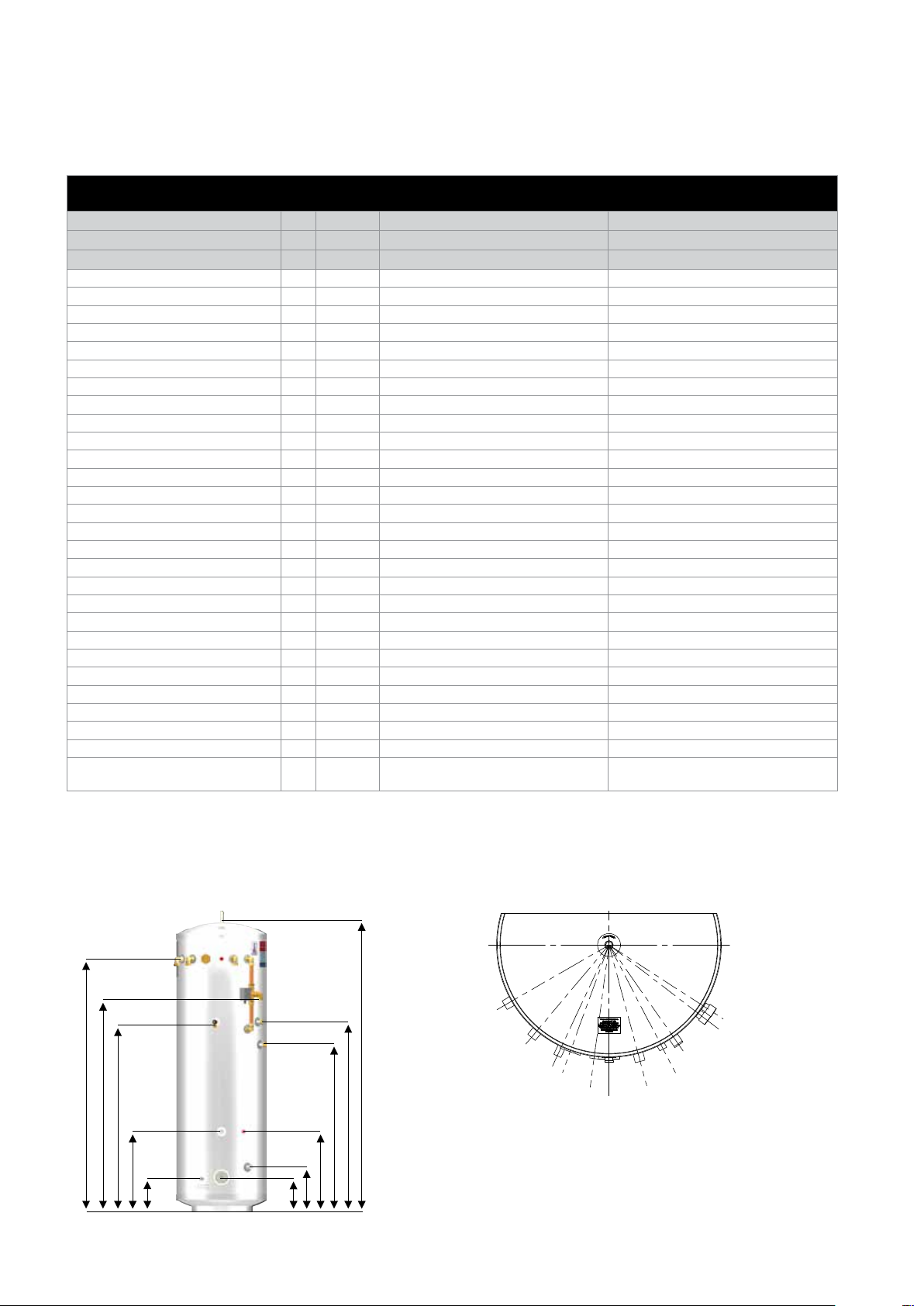
Height mm 1992 2030
Diameter mm 550 630
Buer vent A mm 2000 2037
Buer connections B mm 1657 1752
T&P relief valve C mm 1235 1330
Hot supply D mm 1190 1330
Heat pump ow E mm 1440 1510
Secondary return F mm 1127 1170
Control thermostat (x2) G mm 495 560
Heat pump return H mm 265 310
Immersion heater J mm 220 240
Cold feed K mm 230 230
Primary heat exchanger surface area
Primary heat exchanger thermal rating
Primary heat exchanger pressure loss
Heat up time from 15°C to 50°C
Average domestic hot water
temperature
1
1
1
1
2
2
m
kW 17.91 13.18
bar 0.032 0.032
min 20.47 42.5
°C 46.77 42.06
ASLPAN200HP3SQM70BUF ASLPAN300HP3SQM70BUF
3 3
1. Measured at 0.25 l/s primary ow rate 2. Measured at 0.25 l/s primary ow rate and at 55°C ow temperature
NOTES
1. Recovery times base on Primary Coil/I.H. duty (ie. assumes the heat pump output is adequate).
Buffer CH Flow 60°
Buffer CH Return 40°
Cold Feed 25°
Buffer Inspection Port 20°
T & P Relief Valve 7.5°
Buffer Stat Pocket
Cylinder Stat Pocket
Immersion Heater
Buffer HP Return 15°
B
E
C
G
K
G
H
J
TECHNICAL INFORMATION
A
D
F
Page 4
Secondary Return 57.5°
Hot Supply 52.5°
Buffer HP Flow 35°
Cylinder HP Flow & Return 35°
2nd Cylinder Stat Pocket 27.5°
DESIGN
Table 2
Aquarea Duo Pre-Plumbed GH 200/70L PP Heat Pump Buer GH 300/70L PP Heat Pump Buer
PAW-TE20BUF70PRE-UK PAW-TE30BUF70PRE-UK
Product Stock Code
Energy eciency class C D
Heat loss watts 84 109
Capacity - total volume litres 210 300
Volume heated by IH litres 199 279
Weight - empty/full kg 57/327 61/431
Pressure regulating valve setting bar 3 3
Expansion relief valve setting bar 4.5 4.5
Temperature setting (P&T valve) °C 95 95
Pressure setting (P&T valve) bar 6.0 6.0
Expansion vessel size (volume) litres 24 35
Expansion vessel initial charge pressure bar 3 3
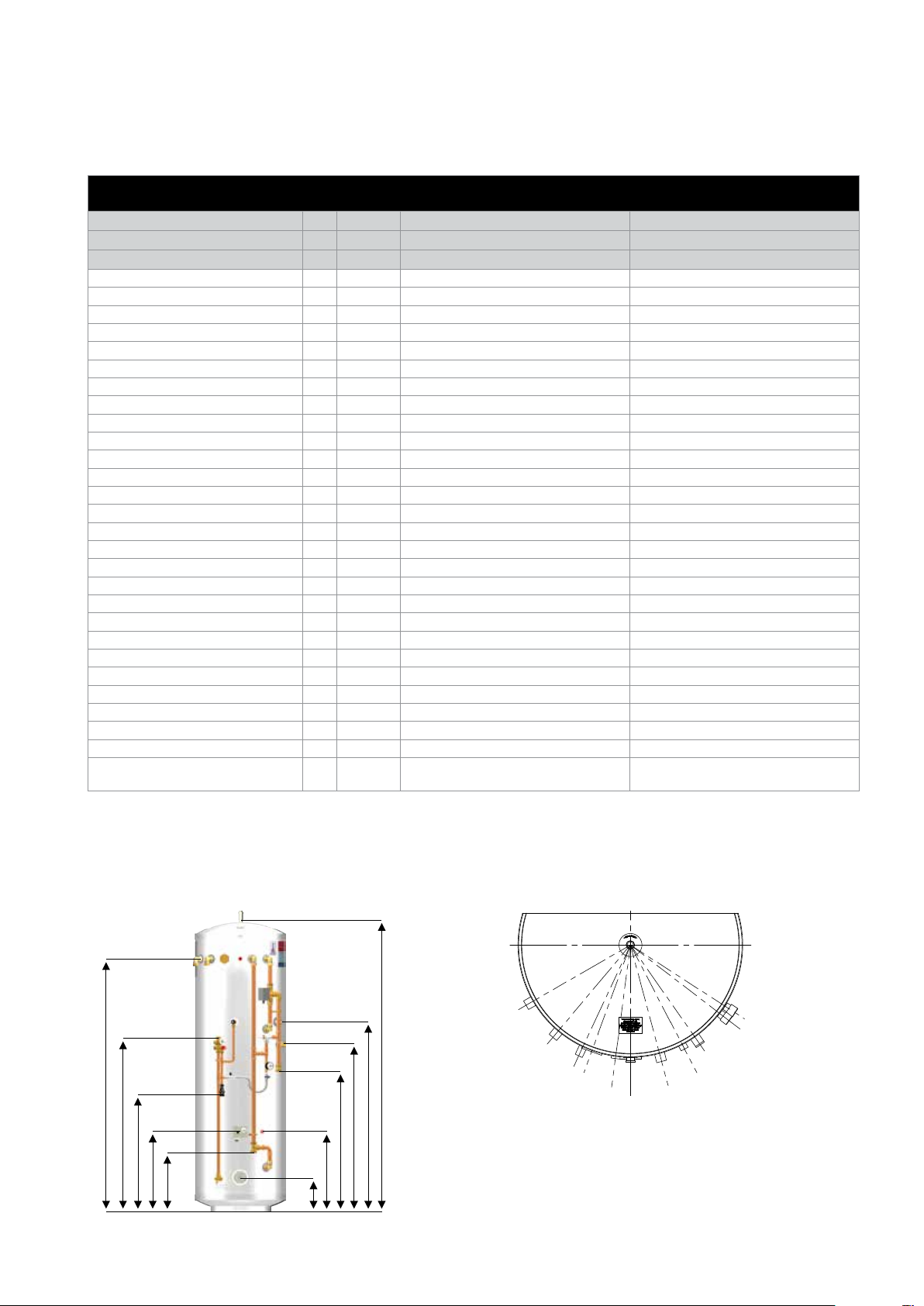
Height mm 1992 2030
Diameter mm 550 630
Buer vent A mm 2000 2037
Buer connections B mm 1657 1752
Cold feed C mm 1110 1205
Hot supply D mm 1190 1330
Tundish E mm 690 825
Secondary return F mm 1127 1170
Heat pump ow G mm 963 1000
Control thermostat (x2) H mm 495 560
Immersion heater J mm 220 240
Heat pump return K mm 390 433
Primary heat exchanger surface area
Primary heat exchanger thermal rating
Primary heat exchanger pressure loss
Heat up time from 15°C to 50°C
Average domestic hot water
temperature
1
1
1
1
2
2
m
kW 17.91 13.18
bar 0.032 0.032
min 20.47 42.5
°C 46.77 42.06
ASLPAN200HP3SQM70BUFPP ASLPAN300HP3SQM70BUFPP
3 3
1. Measured at 0.25 l/s primary ow rate 2. Measured at 0.25 l/s primary ow rate and at 55°C ow temperature
NOTES
1. Recovery times base on Primary Coil/I.H. duty (ie. assumes the heat pump output is adequate).
Buffer CH Flow 60°
Buffer CH Return 40°
B
C
E
H
K
H
J
A
D
F
G
Page 5
Cold Feed 25°
Buffer Inspection Port 20°
T & P Relief Valve 7.5°
Buffer Stat Pocket
Cylinder Stat Pocket
Immersion Heater
Buffer HP Return 15°
TECHNICAL INFORMATION
Secondary Return 57.5°
Hot Supply 52.5°
Buffer HP Flow 35°
Cylinder HP Flow & Return 35°
2nd Cylinder Stat Pocket 27.5°

DESIGN
15
11
13
14
1
4
2
3
8
5
6
7
9
10
11
12
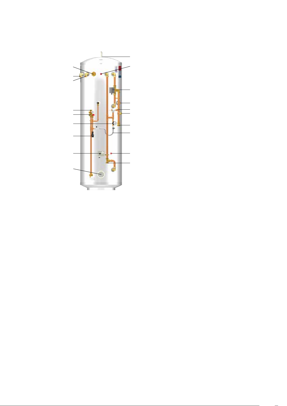
Aquarea Duo Cylinder
Basic Appliance
1. Buer vent / AAV (½” female)
2. CH ow (1” compression)
3. CH return (1” compression)
4. Inspection port (1¾” female)
5. Buer sensor pocket (22mm dual pocket)
6. Buer HP return (1” compression)
7. HP ow (1” compression)
8. T&P relief valve (½” female)
9. Hot supply (¾” compression)
10. Secondary return (¾” compression)
11. Control thermostat (22mm dual pocket)
12. HP return (28mm plain pipe)
13. Immersion heater (1¾” female)
14. Cold feed (22mm plain pipe)
15. Three port motorised valve
Part G3 loose components supplied in a
separate box’
A.
Combination inlet group incorporating
pressure reducing valve, strainer, check valve,
balance cold take o point, expansion relief
valve and expansion vessel connection points.
B. Potable expansion vessels c/w exible hose
and wall bracket
C. Tundish
D. Dual control thermostat and combined
overheat thermostat
E. Wiring junction box for primary system
SYSTEM DESIGN
Page 6
DESIGN
15
17
10
11
13
1
14
16
18
11
12
5
6
8
9
4
2
3
7
Aquarea Duo Pre-Plumb Cylinder
Basic Appliance
1. Buer vent / AAV (½” female)
2. CH ow (1” compression)
3. CH return (1” compression)
4. Inspection port (1¾” female)
5. Buer sensor pocket (22mm dual pocket)
6. Hot supply (¾” compression)
7. Cold feed (¾” compression)
8. Secondary return (¾” compression)
9. HP ow (1” compression)
10. Tundish (22mm compression)
11. Control thermostat (22mm dual pocket)
12. HP return (1” compression)
13. Immersion heater (1¾” female)
14. Three port motorised valve
15.
Combination inlet group incorporating
pressure reducing valve, strainer, check valve,
balance cold take o point, expansion relief
valve and expansion vessel connection points
16. Auto bypass
17. System pressure gauge
18. Filling loop
Part G3 loose components supplied in a
separate box’
A. Potable expansion vessels c/w exible hose
and wall bracket
B. Wiring junction box for primary system
Page 7
SYSTEM DESIGN

Aquarea is a range of unvented hot water storage cylinders, manufactured in the latest
high quality duplex stainless steel. They are designed to provide mains pressure hot
water and are supplied as a package which complies with Section G3 of the Building
Regulations. The appliance is extremely well insulated using high density HCFC free
foam insulation with an ozone depleting potential (ODP) of zero and a global warming
potential (GWP) of 1. It is tted with all necessary safety devices and supplied with all
the necessary control devices to make installation on site as easy as possible.
The Aquarea Duo product is an unvented cylinder and buer tank combined in one
case. It has been specically designed to work with a heat pump source of heat.
The 70 litre buer tank lowers the number of times the heat pump needs to switch
on and o. This extends the life of the compressor in the heat pump. It also enables a
constant ow rate to be maintained through the heat pump heat exchanged which
promotes its ecient operation.
The buer is xed above the 200 or 300 litre hot water cylinder. Both of these hot
water cylinders include a 3m2 highly ecient multi-pass corrugated stainless steel
heat exchanger, and an immersion heater for backup and sterilisation purposes. The
multi pass arrangement of the coil enables high ow rates to be passed through it
with low pressure losses. The immersion heater is usually controlled by the heat pump
control system which determines when it needs to run based upon the parameters
selected by the commissioning engineer.
The product is supplied with; a full divert 3 port valve as the energy cut o and the
PTRV which will prevent any overheating of the DHW cylinder; and the usual inlet
control group and expansion cylinder components required for unvented systems.
Important notes:
1. All Aquarea Duo cylinders are suitable for both open vented and sealed primary
systems. Minimum 5m H2O working pressure.
2. When used with a sealed primary heating system, the heat pump must incorporate
its own over heat thermostat.
3. Aquarea Duo cylinders must not be used with solid fuel boilers or steam as the
heat source.
4. Heat pumps can normally only heat the domestic hot water to between 45
– 50/60°C. The Aquarea heat pump remote controller will operate a cylinder
sterilisation on a weekly basis. See heat pump manual for further details.
5. The cold supply elbow c/w drain tapping must be tted. A exible hose can then
be connected to the drain tapping and providing the hose runs below the lowest
level of the cylinder, then all the water content can be drained out by the symphonic
action. Please refer to the drain down procedure on page 17.
Page 8
INSTALLATION
General Design Considerations
The cupboard footprint needs to be at least 730mm square for units up to 300 litres.
The base chosen for the cylinder should be level and capable of supporting the weight
of the unit when full of water as shown in General Data. The discharge pipework for the
safety valves must have a minimum fall of 1 : 200 from the unit to a safe discharge point.
exposed pipework and ttings on the cylinder should be insulated, and the unit should
NOT be xed in a location where the contents could freeze.
In new systems, pipes should be insulated to comply with building regs, the maximum
permissible heat loss is indicated in the table below, and labelled accordingly as follows:
i. Primary circulation pipes for domestic hot water circuits should be insulated
through their length, subject only to practical constraints imposed by the need
to penetrate joists and other structural elements.
ii. All pipes connected to hot water storage vessels, including the vent pipe, should
be insulated for at least 1 metre from their points of connection to the cylinder (or
they should be insulated up to the point where they become concealed).
In replacement systems, whenever a heat pump or hot water storage vessel is replaced
in an existing system, any pipes that are exposed as part of the work or are otherwise
accessible should be insulated as recommended for new systems, or to some lesser
standard where practical constraints dictate.
The pipe connecting the heat pump ow to the appliance must not be less than
22mm copper or equivalent.
All
Mains Water Supply
Existing properties with a 15mm supply will be
satisfactory provided the local mains pressure
is good, but should be confined to single
bathroom properties. For new properties where
simultaneous demand is required to more than
one bathroom or a bathroom and one or more
en-suites, the communication and service pipe
into the dwelling should be a minimum of 22mm
(usually in the form of a 25mm MDPE supply).
The optimum performance is achieved if the
inlet pressure is 3 bar dynamic. However, the
Aquarea will function with lower inlet pressures,
but this will reduce the performance. There
should be a ow of at least 30 litres per minute
or above available into the property. Normally
Aquarea provides well in excess of 40 litres/min
in most conditions. Flow rates for ALL mains
pressure systems are subject to district pressures
and system dynamic loss. Particularly on larger
properties with more than one bathroom, the
pipe sizes should be calculated in accordance
with
BS EN 806-3:2006 and BS 8558:2011.
Insulation of pipework
Pipe outside diameter Maximum heat loss
15mm 7.89W/m
22mm 9.12W/m
28mm 10.07W/m
35mm 11.08W/m
Further guidance on converting heat loss limits to insulation thickness for specic
thermal conductivities is available in TIMSA “HVAC guidance for achieving compliance
with Part L of the Building Regulations”.
Page 9
INSTALLATION
 Loading...