

Page 1
AQ-C
Miniature DIL 1A control
type for PCBs
Please contact us about TÜV certified products.
AQ-C RELAYS
Compliance with RoHS Directive
ORDERING INFORMATION
AQC
Load current
Nil:
Input module
1A:
Output module
Load voltage
1:
75 to 125 V AC (Output module)
2:
75 to 250 V AC (Output module)
D1:
3 to 60 V DC (Output module)
D3:
4 to 32 V DC (Input module)
Type
Nil:
DC output
IM:
Input module
T:
AC output Random
ZT:
AC output Zero-cross
Input voltage
Output module:
Input module:
Input polarity
Nil:
Standard polarity
R:
Reverse polarity (Only for output module)
5, 12, 24 V DC
4/24 V DC, 100/240 V AC
FEATURES
• Compact DIL type:
L20 mm × W10 mm × H12.8 mm
(.787×.394×.504 inch)
• Excellent in noise resistance
•Snubber circuit integrated
• High dielectric strength: 2,500 V
between input and output
•Reverse polarity type available
TYPICAL APPLICATIONS
• Compact AC motor, Solenoid,
Magnet, Driver of magnetic valve
• Copying equipment
• NC machine, Robot
•Programmable controller
• Air conditioners
TYPES
1. Input module
Type Output voltage Input voltage Part No.
AC input 4 to 32 V DC 80 to 250 V AC AQCD3-IM 100/240 V AC
DC input 4 to 32 V DC 3 to 32 V DC AQCD3-IM 4/24 V DC
Standard packing: Carton: 50 pcs.; Case: 500 pcs.
All Rights Reserved © C
OPYRIGHT Panasonic Electric Works Co., Ltd.
Page 2
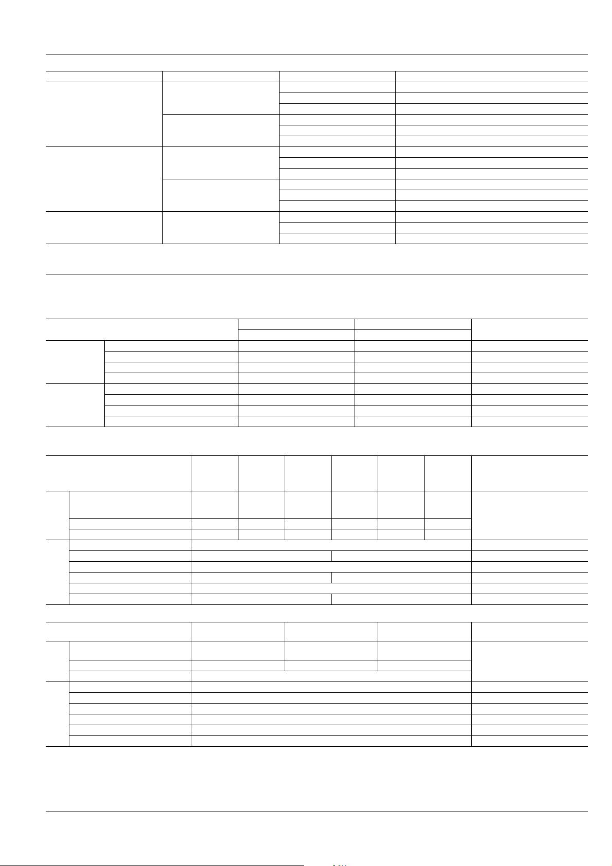
2. Output module
Type Load voltage Input voltage Part No.
5 V DC AQC1A1 - ZT5 V DC
75 to 125 V AC
AC output Zero-cross
75 to 250 V AC
75 to 125 V AC
AC output Random
75 to 250 V AC
DC output 3 to 60 V DC
Standard packing: Carton: 50 pcs.; Case: 500 pcs.
Note: Reverse polarity type (AQC5∗∗ and AQC6∗∗) is also produced by lot after receipt of order.
12 V DC AQC1A1 - ZT12 V DC
24 V DC AQC1A1 - ZT24 V DC
5 V DC AQC1A2 - ZT5 V DC
12 V DC AQC1A2 - ZT12 V DC
24 V DC AQC1A2 - ZT24 V DC
5 V DC AQC1A1 - T 5 V DC
12 V DC AQC1A1 - T 12 V DC
24 V DC AQC1A1 - T 24 V DC
5 V DC AQC1A2 - T 5 V DC
12 V DC AQC1A2 - T 12 V DC
24 V DC AQC1A2 - T 24 V DC
5 V DC AQC1AD1- 5 V DC
12 V DC AQC1AD1- 12 V DC
24 V DC AQC1AD1- 24 V DC
SPECIFICATIONS
Rating [at 20°C 68°F; Input voltage ripple (output module) and output voltage ripple (input module): max. 1%]
1. Input module
Item
Input side
Output side
Input voltage 80 to 250 V AC 3 to 32 V DC
Input current Max. 5 mA Max. 5 mA
Pick-up voltage Max. 80 V AC Max. 3 V DC
Drop-out voltage Min. 10 V AC Min. 1 V DC
Load voltage 4 to 32 V DC 4 to 32 V DC
Load current 0.1 to 25 mA 0.1 to 25 mA
Max. “OFF-state” leakage current Max. 5µA Max. 5µA When 32 V DC applied
Max. “ON-state” voltage drop Max. 1.6 V Max. 1.6 V at max. carrying current
Type
2. Output module
(1) AC output type
Type
AQC1A1-
ZT5VDC
Item
Input voltage
Input
side
Input impedance (Approx.) 0.3 kΩ 0.8 kΩ 1.8 kΩ 0.3 kΩ 0.8 kΩ 1.8 kΩ
Drop-out voltage, min 0.5 V 1.2 V 2.4 V 0.5 V 1.2 V 2.4 V
Max. load current 1 A*
Load voltage 75 to 125 V AC 75 to 250 V AC
Non-repetitive surge current 20 A*
Load
side
Max. “OFF-state” leakage current 0.6 m A (When 100 V AC applied) 1.1 m A (When 200 V AC applied) at 60 Hz
Max. “ON-state” voltage drop 1.6 A at max. carrying current
Min. load current 10 mA*
AQC1A1-
T5VDC
(5 V type)
4 to 6
V DC
AQC1A1-
ZT12VDC
AQC1A1-
T12VDC
(12 V type)
9.6 to 14.4
(2) DC output type
Item
Input voltage
Input
Input impedance (Approx.) 0.43 kΩ 1.2 kΩ 2.8 kΩ
side
Drop-out voltage, min 0.8 V
Max. load current 1 A*
Load voltage 3 to 60 V DC
Non-repetitive surge current 1.5 A*
Load
side
Max. “OFF-state” leakage current 0.1 m A (When 60 V DC applied)
Max. “ON-state” voltage drop 1.6 V at max. carrying current
Min. load current 1 mA*
Notes: *1. Refer to REFERENCE DATA “1. Load current vs. ambient temperature”.
*2. Refer to REFERENCE DATA “2. Non-repetitive surge current vs. carrying time”.
*3. Refer to REFERENCE DATA “3. Input current vs. input voltage characteristics”.
*4. When the load current is less than the rated minimum load current, please refer to “Cautions for Use of SSR”.
Type
AQC1AD1-5VDC AQC1AD1-12VDC AQC1AD1-24VDC Remarks
(5 V type)
4 to 6 V DC
AC input DC input
AQCD3-M 100/240 V AC AQCD3-IM 4/24 V DC
V DC
AQC1A1-
ZT24VDC
AQC1A1-
T24VDC
(24 V type)
21.6 to 26.4
V DC
4
9.6 to 14.4 V DC
AQC1A2-
AQC1A2-
(5 V type)
1
2
(12 V type)
1
2
4
ZT5VDC
T5VDC
4 to 6
V DC
AQC1A2-
ZT12VDC
AQC1A2-
T12VDC
(12 V type)
9.6 to 14.4
V DC
4
20 mA*
(24 V type)
21.6 to 26.4 V DC
(24 V type)
21.6 to 26.4
AQC1A2-
ZT24VDC
AQC1A2-
T24VDC
V DC
3
*
Ta = Max. 40°C 104°F
In one cycle at 60 Hz
3
*
Ta = Max. 40°C 104°F
at 1s
AQ-C
Remarks
Remarks
All Rights Reserved © C
OPYRIGHT Panasonic Electric Works Co., Ltd.
Page 3

AQ-C
Characteristics [at 20°C 68°F; Input voltage ripple (output module) and output voltage ripple (input module): max. 1%]
Input module
Item
Type
Operate time, max. 20 ms 0.5 ms Input voltage: 24 V DC or 100V AC
Release time, max 20 ms 0.5 ms
Insulation resistance, min. 10
Breakdown voltage 2,500 Vrms between input and output For 1 minute
Vibration
resistance
Shock
resistance
Destructive 10 to 55Hz double amplitude of 3 mm 1 hour for X,Y, Z, axis
Functional 10 to 55Hz double amplitude of 3 mm 10 minutes for X,Y, Z, axis
Destructive Min. 980 m/s
Functional Min. 980 m/s2 {100 G} 4 time each for X,Y,Z axis
Ambient temperature –30°C to +80°C –22°F to +176°F
Storage temperature –30°C to +100°C –22°F to +212°F
Output module
Type
Item
Operate time, max. 1 ms 1/2 cycle of voltage sine wave + 1ms 0.5 ms
Release time, max. 1/2 cycle of voltage sine wave + 1ms 1 ms
Insulation resistance, min. 10
Breakdown voltage 2,500 Vrms between input and output For 1 minute
Vibration
resistance
Shock
resistance
Ambient temperature –30°C to +80°C –22°F to +176°F
Storage temperature –30°C to +100°C –22°F to +212°F
Operational method Random Turn-ON, Zero-cross Turn-OFF Zero-cross (Turn-ON and Turn-OFF) —
Destructive 10 to 55Hz double amplitude of 3 mm 1 hour for X,Y, Z, axis
Functional 10 to 55Hz double amplitude of 3 mm 10 minutes for X,Y, Z, axis
Destructive Min. 980 m/s
Functional Min. 980 m/s2 {100 G} 4 time each for X,Y,Z axis
AC Input DC Input Remarks
Output voltage: 24 V DC
Output current: 25mA
9
Ω between input and output at 500 V DC
2
{100 G} 5 time each for X,Y,Z axis
AC output
Random Zero-cross
9
Ω between input and output at 500 V DC
2
{100 G} 5 time each for X,Y,Z axis
DC output Conditions
REFERENCE DATA
1. Load current vs. ambient temperature
(AC/DC output)
1.0
0.8
0.6
Load current, A
0.4
0.2
0
–30 0 20 40 60 80
3. Input current vs. input voltage characteristics
(AC/DC output)
30
25
20
15
Input current, mA
10
(5 V type)
5
0
0102030
Ambient temperature, °C
(12 V type)
Input voltage, V
(24 V type)
AC output
DC output
2.-(1) Non-repetitive surge current vs. carrying
time (AC output)
30
20
10
Non-repetitive surge current, A
0
1234571020 3040 50 70100
No. of cycles at 60 Hz
4.-(1) Input current vs. input voltage
characteristics (AC input)
Tested sample: AQCD3-IM100/240 V AC, 5 pcs.
10
8
6
Input current, mA
4
2
0
100 200 300
Input voltage, V AC
2.-(2) Non-repetitive surge current vs. carrying
time (DC output)
5
4
3
2
Non-repetitive surge current, A
1
0
10 20 30 4050 70 100 200 300 1,000
Carrying time, ms
4.-(2) Input current vs. input voltage
characteristics (DC input)
Tested sample: AQCD3-IM4/24 V DC
10
9
8
7
6
5
4
Input current, mA
3
2
1
0
5101520253035
Input voltage, V DC
All Rights Reserved © C
OPYRIGHT Panasonic Electric Works Co., Ltd.
Page 4

5. Load current vs. ambient temperature
The CAD data of the products with a CAD Data mark can be downloaded from: http://panasonic-electric-works.net/ac
7.62
7.6210.16
4-1.1 dia.
4-.043 dia.
Terminal 1
Terminal 5
Terminal 8
Terminal 16
.300
.300.400
7.62
7.6210.16
4-1.1 dia.
4-.043 dia.
Terminal 1
Terminal 5
Terminal 8
Terminal 16
.300
.300.400
characteristics for adjacent mounting
AQ-C
1.0
0.8
0.6
Load current, A
0.4
0.2
=Adjacent mounting pitch
0
–30 0 20 40 60 80
Ambient temperature, °C
=20.32 mm
.800 inch
=12.7 mm
.500 inch
DIMENSIONS (mm inch)
1. Input module (AC, DC)
CAD Data
AC input
…
5
…
8
…
r
…
1
Case color: Yellow Case color: White
Output: DC –
Output: DC +
Input: AC
Input: AC
10
.394
2.7
.106
0.3 0.3
.012 .012
DC input
…
5
…
8
…
r
…
1
Output: DC –
Output: DC +
Input: DC +
Input: DC –
0.8
.031
2.7
5.5
.217
0.3
.012
.106
0.4
.016
7.62
.300
0.8
.031
20
.787
10.16 7.62
.400 .300
1
r
0.3
.012
58
12.5
.492
0.3
.012
0.4
.016
3.9
.154
General tolerance: ±0.5 ±.020
PC board pattern (Copper-side view)
Tolerance: ±0.1 ±.004
Schematic
16
1
Specified polarities for
DC types are shown in
the parentheses.
Load
+
–
58
Load power
source
(+)
Input power
source
(–)
2. Output module (AC, DC)
CAD Data
ACCESSORY
10
.394
2.7
.106
0.3 0.3
.012 .012
AC output
…
5
Output: AC
…
8
Output: AC
…
r
Input: DC +
…
1
Input: DC –
Case color: Black Case color: Red
DC output
…
5
Output: DC –
…
8
Output: DC +
…
r
Input: DC +
…
1
Input: DC –
2.7
.106
5.5
.217
0.3
0.8
.031
.012
0.4
.016
7.62
.300
0.8
.031
20
.787
10.16 7.62
.400 .300
1
r
General tolerance: ±0.5 ±.020
0.3
.012
58
12.5
.492
0.3
.012
0.4
.016
3.9
.154
PC board pattern (Copper-side view)
Tolerance: ±0.1 ±.004
Schematic
16
58
Load
1
Specified polarities for
(+) (–)
Load power source
DC types are shown in
the parentheses.
+
–
Input power
source
PC1A-PS
All Rights Reserved © C
OPYRIGHT Panasonic Electric Works Co., Ltd.
Page 5

AQ-C
NOTE
When used for the load less than rated
In the case of the load current less than
rated, malfunction may result from the
residual voltage across the both ends of
the load even if the solid state relay is
turned off.
Use a dummy resistor as a
countermeasure.
The total of the current through the
resistor and the load current must exceed
the min. rated load current.
R0(Dummy resistor)
(+)
Load power source
(–)
Load
8
5
161
In case the dummy resistor is not used,
keep in mind that the residual voltage
becomes as follows:
Example:
For the inductive load by the 5 mA load
current and the 200 V AC load voltage,
the load impedance becomes 40 kW and
Ve/V = 16% is estimated from the below
graph.
Accordingly, the 32 V voltage remains
across the both ends of the load when
the solid state relay is turned off.
• Characteristics of residual voltage
vs. load impedance
100
f = 60 Hz
Ve: Residual voltage
V: Power voltage
80
Load
1
SSR
60
Ve
100,%
×
V
2
40
20
0
20 40
Ve
V
Power facto r: 1
(resistive load)
Power facto r: 0.4
(inductive load)
60 80 100
Load impedance, kΩ
Input power source
For Cautions for Use.
+–
All Rights Reserved © C
OPYRIGHT Panasonic Electric Works Co., Ltd.
 Loading...