

Panasonic AN8746SA Datasheet
ICs for Compact Disc/CD-ROM Player
AN8746SA
PWM driver IC for portable CD player
■ Overview
The AN8746SA is a 4-channel actuator/motor
drive IC by DMOS direct PWM method for a
portable CD player.
■ Features
• RON = 1.8 Ω (typ.)
• Supply voltage range
(Control block: 2.0 V to 3.6 V, power block: 1.2 V
to 3.6 V)
• Current at standby
(Control block: 1 µA or less, power block: 1 µA or
less)
• With an output pin of monitoring 1/2 of the power
supply voltage
■ Applications
• Portable CD player
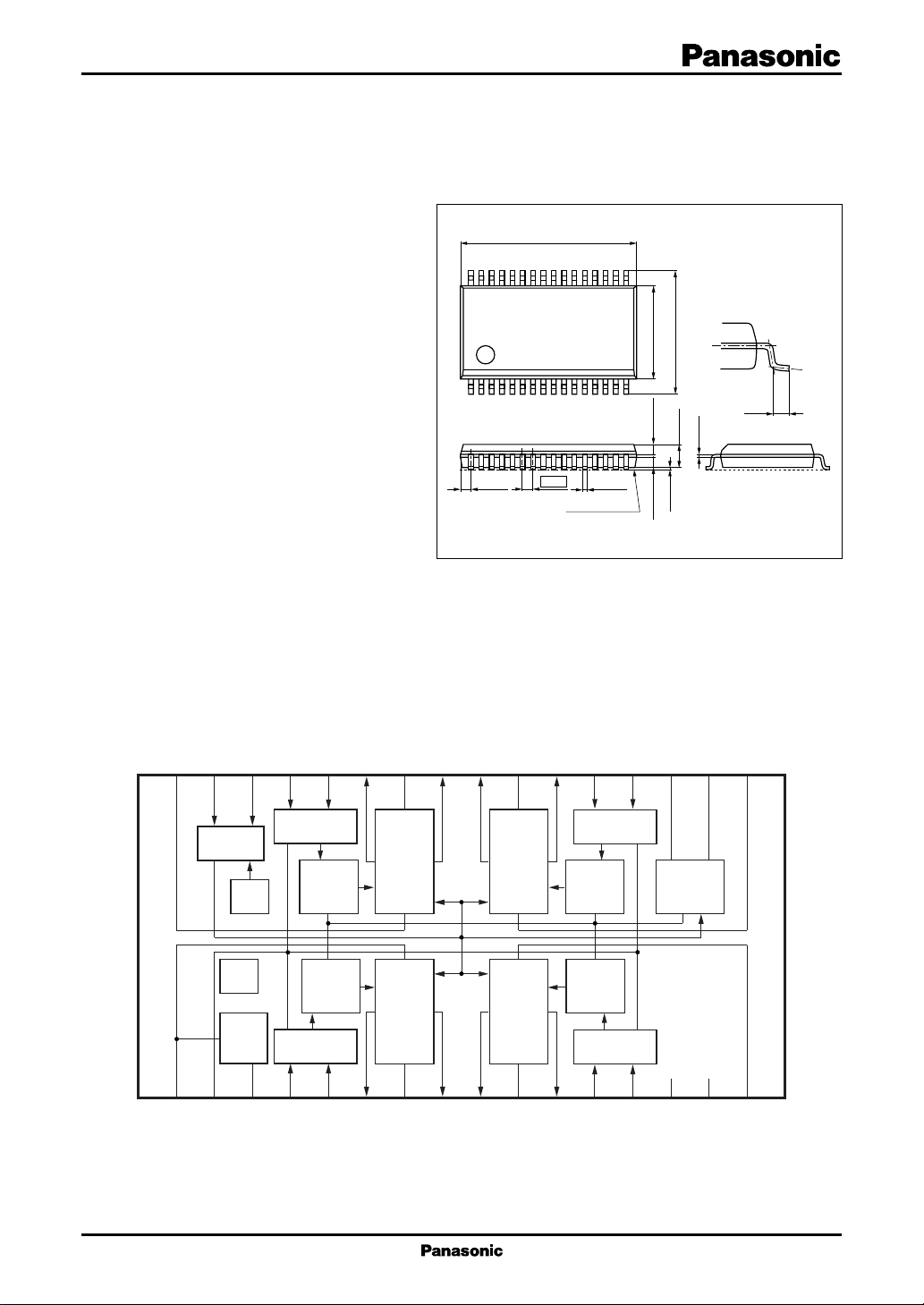
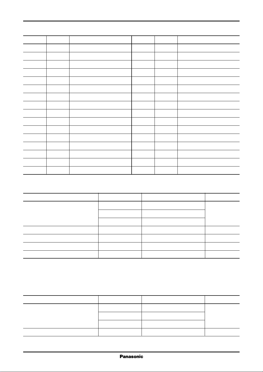
■ Block Diagram
11.0±0.3
32
116
(0.625)
0.65
Seating plane
17
8.1±0.3
6.1±0.3
1.5±0.2
0.65±0.100.65±0.10
+0.10
0.3
–0.05
0.1±0.1
SSOP032-P-0300
+0.10
(0.5)
–0.05
0.2
Unit: mm
VM4AC
32
1
M1
V
31
Reset
VBG
monitor
2
C
V
V
30
TSD
M1
3
PC
Fi4
29
Logic circuit
Logic circuit
4
Fi1
MON
28
Pre-
driver
Pre-
driver
5
Ri4
Ri1
27
6
Ro4
bridge
bridge
Ro1
PGND4
26
H
H
7
PGND1
25
8
18
M3
17
Fo4
Fo3
PGND3
Ro3
Ri3
Fi3
VGIVGOV
24
23
22
21
20
19
Logic circuit
H
bridge
Pre-
driver
V
G
limiter
Pre-
H
driver
bridge
Logic circuit
9
10
11
12
13
14
15
16
Fo1
Fo2
Ro2
Ri2
GND
Fi2
N.C.
M2
V
PGND2
1
AN8746SA ICs for Compact Disc/CD-ROM Player
■ Pin Descriptions
Pin No. Symbol Description
1VM1Ch. 1 power supply
2VCControl circuit power supply
3 MON VM1 monitor
4 Fil Ch. 1
5 Ril Ch. 1
6 Rol Ch. 1
forward direction input pin
reverse direction input pin
reverse direction output pin
7 PGND1 Ch. 1 power ground
8 Fo1 Ch. 1
9 Fo2 Ch. 2
forward direction output pin
forward direction output pin
10 PGND2 Ch. 2 power ground
11 Ro2 Ch. 2
12 Ri2 Ch. 2
13 Fi2 Ch. 2
reverse direction output pin
reverse direction intput pin
forward direction input pin
14 GND Control circuit ground
15 N.C.
16 V
Ch. 2 power supply
M2
Pin No. Symbol Description
17 V
18 V
19 V
20 Fi3 Ch. 3
21 Ri3 Ch. 3
22 Ro3 Ch. 3
Ch.3 power supply
M3
Gate voltage clamp output
GO
Gate voltage input pin
GI
forward direction input pin
reverse direction input pin
reverse direction output pin
23 PGND3 Ch. 3 power ground
24 Fo3 Ch. 3
25 Fo4 Ch. 4
forward direction output pin
forward direction output pin
26 PGND4 Ch. 4 power ground
27 Ro4 Ch. 4
28 Ri4 Ch. 4
29 Fi4 Ch. 4
reverse direction output pin
reverse direction input pin
forward direction input pin
30 PC Power cut pin
31 AC All cut-off pin
32 V
Ch. 4 power supply
M4
■ Absolute Maximum Ratings
Parameter Symbol Rating Unit
Supply voltage V
Supply current I
2
Power dissipation
Operating ambient temperature
Storage temperature
Note)*1: Except for the operating ambient temperature and storage temperature, all ratings are for Ta = 25°C.
2: Use within the range of PD = 390 mW or less at Ta = 75°C, following the allowable power dissipation characteristic curve
*
of "■ Application Notes".
*
1
*
1
*
C
V
M
V
GI
DD
P
D
T
opr
T
stg
5V
7
8.2
500 mA
400 mW
−30 to +75 °C
−55 to +150 °C
■ Recommended Operating Range
Parameter Symbol Range Unit
Supply voltage V
Signal input voltage V
C
V
M
V
GI
IN
2.0 to 2.4 to 3.6 V
1.2 to 2.4 to 3.6
VM +3.5 to 7.0 to 8.0
0 to V
C
V
2
 Loading...