

Panasonic AN7555NZ Datasheet
ICs for Audio Common Use
AN7555NZ
BTL output power IC for car audio
■ Overview
The AN7555NZ is an audio power IC developed as
the sound output of car audio (35 W × 4-channel). It has
realized the voltage gain of 40 dB based on the AN7560Z
(voltage gain: 34 dB). A capacitor and resistor to stop
oscillation are built in between the output pin and GND so
that a space saving of set is possible. Also, it incorporates a perfect muting circuit without shock noise, so that
a shock noise design under the set transient condition
can be made easily when used together with its standby
function. In addition, it incorporates various protection
circuits to protect the IC from destruction by GND-open
short circuit to ground, and power supply surge which are
the important subject of power IC protection. This IC
will largely contribute to a high reliability design of the
equipment.
■ Features
• A pattern layout in which input and output pattern do
not intersect each other on single-sided printed circuit
board is possible.
• Incorporating various protection circuits (temperature
protection, short circuit to V
to V
, short circuit to GND, GND-open short circuit to
CC
GND, overvoltage, power supply surge, and ASO, etc.)
• Built-in standby function (shock-noise free at STB-on/
off)
• Built-in muting function (shock-noise free at Mute-on/
off)
• External components reduction
• Provided with beep sound input pin
• Equipped with auxiliary sound input pin
• Voltage gain: 40 dB
(AN7560Z/AN7561Z: Voltage gain: 34 dB)
, VCC-open short circuit
CC
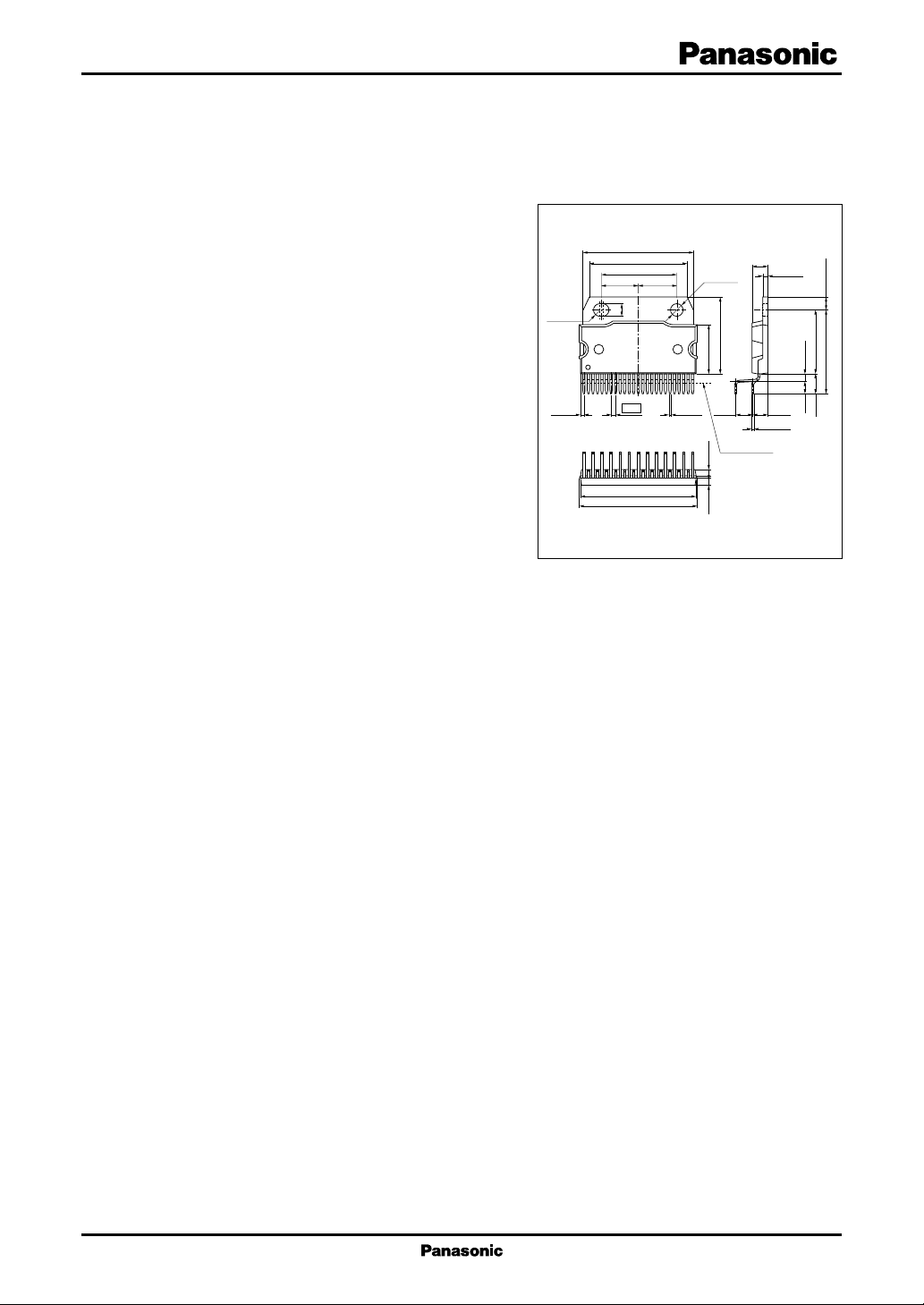
31.0±0.3
27.0±0.3
21.0±0.1
(10.50)(10.50)
R1.8±0.1
125
(1.26)
3.6±0.1
1.27
33.0±0.3
33.36±0.30
+0.2
0.6
–0.1
4.5±0.2
φ3.6±0.1
15.5±0.3
14.5±0.3(1.95) (2.15)
(5.08) (4.29)
Seating plane
HZIP025-P-0980
Unit: mm
1.5±0.1
+0.15
0.40
–0.05
(3.30) 2.4±0.5
(5.70) 18.75±0.30
(24.45) 3.75±0.10
■ Applications
• Car stereo, miniature audio component, karaoke and
other audio equipment
1
AN7555NZ ICs for Audio Common Use
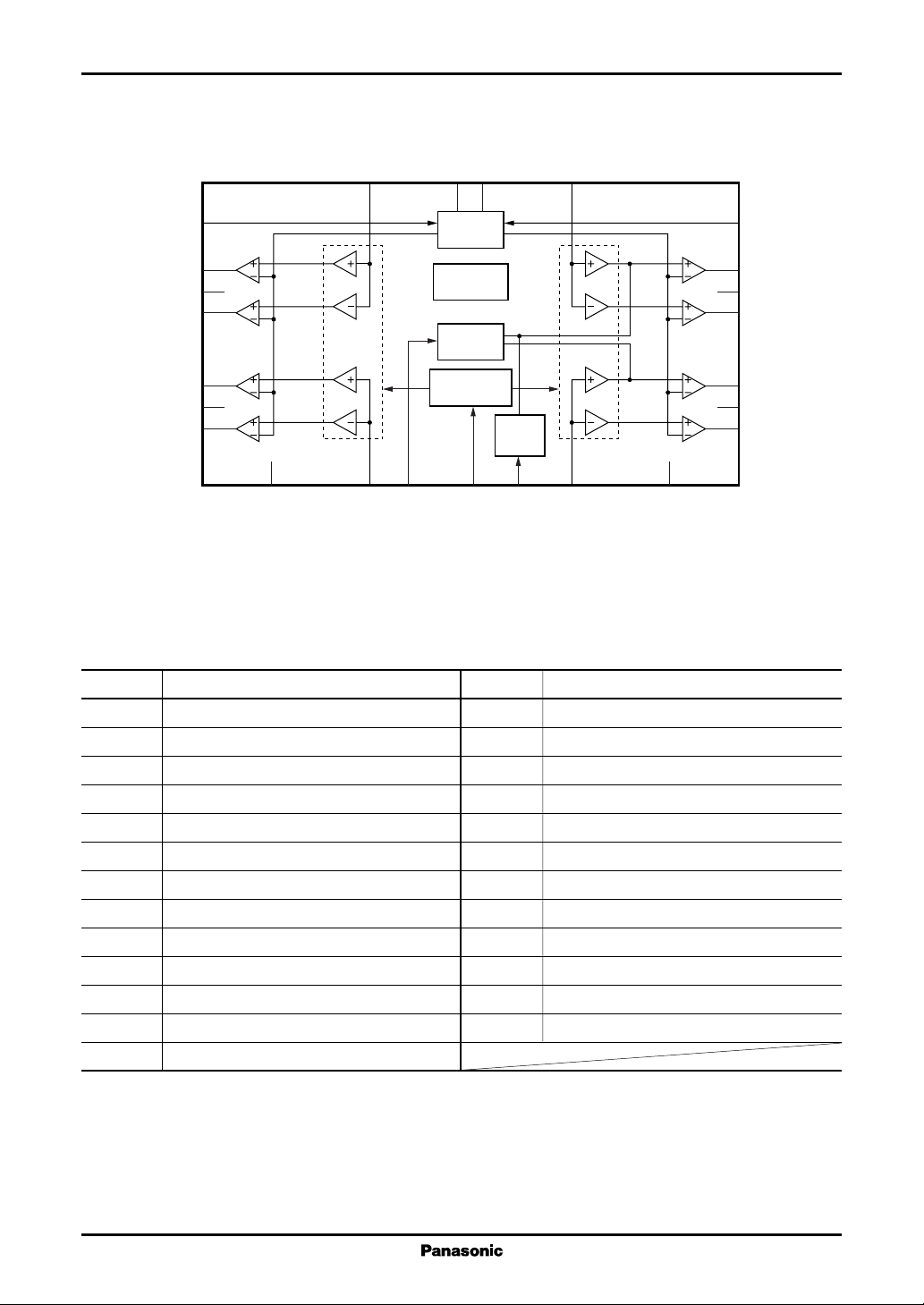
■ Block Diagram
CC
CC
V
V
18
4
12
Ripple
filter
Protection
circuit
Beep
input
Attenuation
control
24
AUX
input
10
19
17
22
16
9
8
GND (output)
11
13
14
GND (output)
15
GND (output)
GND (output)
25
1
2
3
5
6
7
21
Attenuator Attenuator
20
23
Beep
GND (input)
Muting
AUX
GND (sub)
■ Pin Descriptions
Pin No. Description
1 Ch.4 + output
2 GND (ch.4 output)
3 Ch.4 − output
4 Supply voltage V
CC
5 Ch.3 + output
6 GND (ch.3 output)
7 Ch.3 − output
8 GND (ch.3 output)
9 Ch.2 + output
10 AUX input
11 Ch.2 − output
12 Supply voltage Vcc
13 Ch.1 + output
Note) It is not necessary to connect capacitor and resistor for stopping the oscillation at the output terminals.
Use them after check if necessary for noise countermeasure.
Pin No. Description
14 GND (ch.1 output)
15 Ch.1 − output
16 Standby
17 Ch.1 input
18 Beep input
19 Ch.2 input
20 GND (input)
21 Ch.4 input
22 GND (printed circuit board)
23 Ch.3 input
24 Muting
25 Ripple filter
2
 Loading...