

Panasonic AN7273S, AN7273 Datasheet
ICs for FM/AM Tuner
■ Overview
The AN7273 and the AN7273S are the ICs designed
for Hi-Fi stereo tuner. They are functioned with stop signal
pin besides the AN7223S function.
■ Features
•
Level meter output (FM–AM common use)
•
Stop signal output (for synthesizer tuner)
•
AM : including RF amplifier and high sensitivity
•
Low power consumption
•
Low shock noise level from function switch operation
•
Fewer external parts
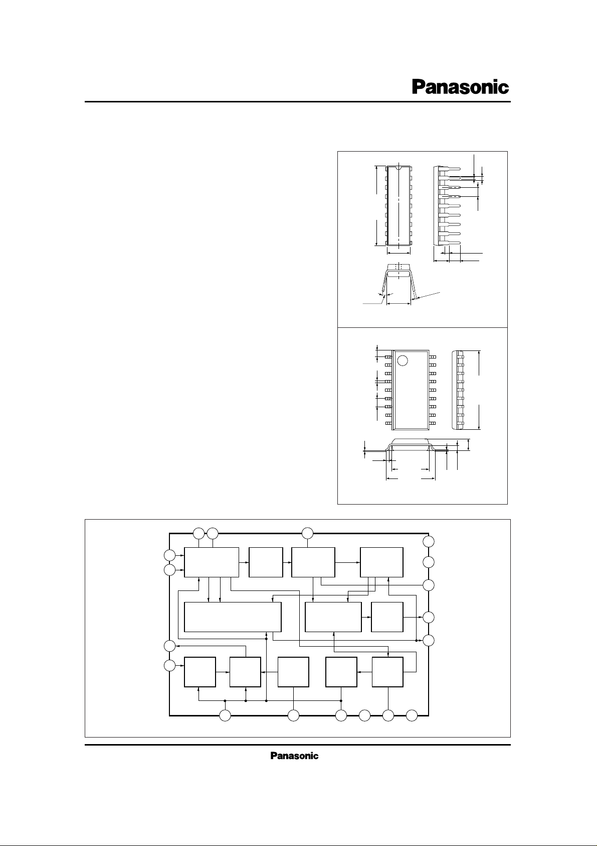
AN7273, AN7273S
AM Tuner, FM/AM IF Amplifier Circuit
8 9
1
7
4
3
5 18 6 2 10 11
15
13
16
17
14
12
AM–FM
IF Amp.
FM IF
Amp.
FM
Quad. Det.
Mute Det.
AF Amp.
Mute or Shock
Noise Canceller
Level Meter
AM
Mixer
AM RF
Amp.
AM
L. Osc.
AGC
AM Det.
GNDV
CC (AM)
V
CC
V
REF
■ Block Diagram
1
2
3
4
5
6
7
8
3 ~ 15˚
7.62±0.25
0.3
+ 0.1
– 0.025
3.8±0.25
(3.45)
0.51min.
2.54
1.2±0.25
0.5±0.1
Unit : mm
6.3±0.25
18
17
16
15
14
13
12
11
21.7±0.3
9 10
AN7273
18-Lead DIP Package (DIP018-P-0300E)
AN7273S
1
1.3
0.4±0.25
1.27
9
0.1
0.3
5.4±0.3
7.7±0.3
18-Lead SOP Package (SOP018-P-0300)
Unit : mm
18
12.6±0.3
10
1.2±0.3
0.65
0.15
AN7273, AN7273S
ICs for FM/AMTuner
Pin No.
Pin Name
1
2
3
4
5
6
7
8
9
FM IF Input
AM Supply/Mute Adjustment
AM RF Input
AM Mixer Output
AGC Output (2)
AGC Output (1)
AM IF Input
IF By-pass
IF By-pass
■ Pin Descriptions
Pin No.
Pin Name
10
11
12
13
14
15
16
17
18
AM Detection Output
GND
FM Detection Coil
AF Output
V
CC
Level Meter Output
AFC Output
Reference Voltage
Local Oscillation Coil
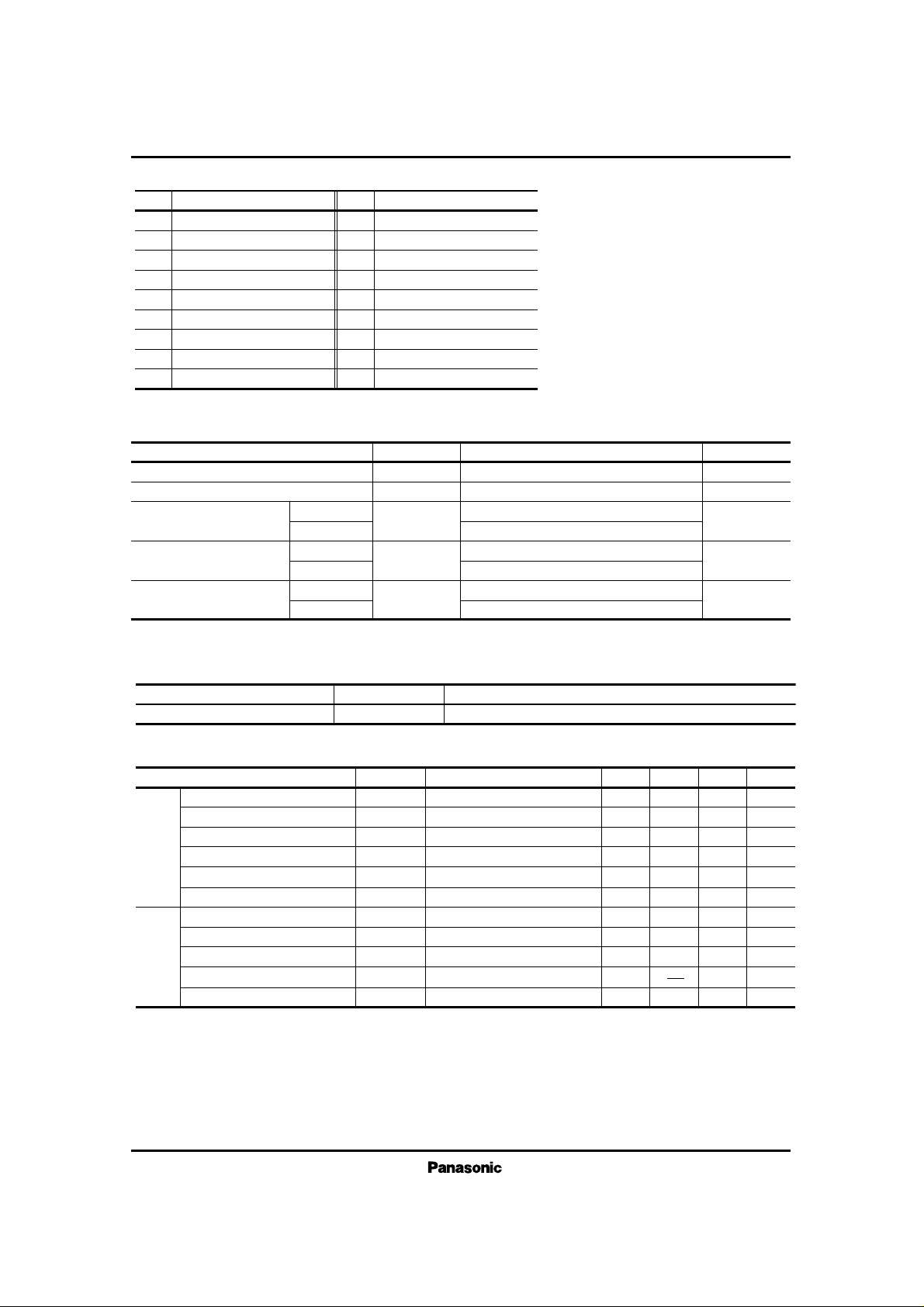
Parameter Symbol Rating Unit
P
D
T
opr
T
csg
V
CC
I
CC
AN7273
AN7273S
AN7273
AN7273S
AN7273
AN7273S
Power Dissipation
Operating Ambient Temperature
Storage Temperature
Supply Voltage
Supply Current
mW
˚C
˚C
V
mA
14.4
30
317
*
1
210
*
2
–20 ~ + 75
–20 ~ + 75
–55 ~ + 150
–55 ~ + 125
*
1 Ta = 25˚C, *2 Ta = 75˚C
■ Absolute Maximum Ratings (Ta=25˚C)
DC measurement
V
i
=80dBµ
Input at V
O
= –3dB
Input at V
O
=more than –20dB
V
i
=70dBµ
V
i
=100dBµ
DC measurement
Vi =80dBµ
Input at V
O
=10mV
V
i
= –10dBµ
V
i
=80dBµ
Parameter Symbol Condition min. typ. max. Unit
■ Electrical Characteristics (VCC= 5V, Ta= 25˚C)
I
tot
V
O
V
i (lim)
V
i (Mute)
V
15–11
V
15–11
I
tot
V
O
S
max.
V
15–11
V
15–11
9
75
43.5
55
0.61
1.14
8
60
4
0
1.12
14
100
46
64
0.8
1.26
13
80
9.5
1.25
20
125
49.5
73
1.1
1.42
19
100
15
130
1.38
mA
mV
dBµ
dBµ
V
V
mA
mA
dBµ
mV
V
Total Circuit Current
Demodulation Output Level
Limiting Sensitivity
Muting Sensitivity
Level Meter Driving Output (1)
Level Meter Driving Output (2)
Total Circuit Current
Detection Output Level
Max. Sensitivity
Level Meter Driving Output (1)
Level Meter Driving Output (2)
Note) Unless otherwise specified, f
i
=10.7MHz, Mod. = 22.5kHz, fm = 400Hz (FM)
f
i
=1MHz, Mod. = 30%, fm = 400Hz (AM)
FM
AM
Parameter Symbol Range
■ Recommended Operating Range (Ta = 25˚C)
Operating Supply Voltage Range
V
CC (opr)
3 ~ 12V
 Loading...