

Panasonic AN7259S Datasheet

ICs for FM/AM Tuner
■ Overview
The AN7259S is an FM–IF/DET IC for car radio/car
stereo and has each function necessary for electronictuner.
■ Features
•
Quadrature detection system and fewer external parts
•
Good linearity of control voltage output used for AGC
and separation control, etc.
•
IF counter output and search output in channel selection signal as electronic tuning and with IF counter output ON/OFF circuit (SSC)
•
Adjustment of search band width and search output
center frequency
•
Soft muting adjusting function
AN7259S
FM-IF Amplifier Circuit for Car Radio
20 19 18 17 16 15 14 13 12 11
1 2 3 4 5 6 7 8 9 10
FM IF Amp.
V
CONT.
Search
Counter
SSC
FM Det.
Mute
Amp.
GND V
CC
■ Block Diagram
Unit : mm
0.1±0.1
1.5±0.2
0.3
0.65
0.15
0.4
1
2
3
4
5
6
7
8
9
10
20
19
18
17
16
15
14
13
12
11
0.4±0.25
1.27
12.6±0.3
5.4±0.3
7.7±0.3
20-Lead SOP Package (SOP020-P-0300A)
AN7259S
ICs for FM/AM Tuner
■ Absolute Maximum Ratings (Ta=25˚C)
V
CC
I
CC
P
D
T
opr
T
stg
Supply Voltage
Supply Current
Power Dissipation (Ta = 75˚C)
Operating Ambient Temperature
Storage Temperature
V
mA
mW
˚C
˚C
Parameter Symbol Rating Unit
9.6
23
230
–30 ~ + 75
–55 ~ + 125
■ Recommended Operating Range (Ta=25˚C)
Parameter Symbol Range
Operating Supply Voltage Range
V
CC
7.3V ~ 9.6V
Input at VO = –3dB
V
in
= 70dBµ
V
in
= 0dBµ, Pin9 –14 voltage
V
in
= 0dBµ, Pin2 voltage
V
SIG4 –VSIG1
V
SIG5 –VSIG4
V
in
= 70dBµ, Pin2 voltage
V
in
= 100dBµ, Pin2 voltage
Band width at Pin4 DC voltage =
2.5V,
R = 30kΩ
V
in
= 0dBµ
Mod.
= 30%, V
in
= 100dBµ
Mod.
= 100%, V
in
= 100dBµ
Mod.
= 30%, V
in
= 100dBµ
Pin16, 10.7MHz Output
AM = 30% Mod.,
FM
= 30% Mod.
V
in
= 0dBµ
Referred to Input
Parameter Symbol Condition min. typ. max. Unit
■ Electrical Characteristics (V
CC
= 8V, FM 1kHz 30%Modulation, Ta= 25˚C)
V
lim
V
O
V
offset
V
SIG1
V
SIG2
V
SIG3
V
SIG4
V
SIG5
BW
I
tot
26.5
150
–240
0.19
2.51
1.15
2.92
4.11
145
15
30
32.5
210
240
0.85
3.33
1.75
3.98
5.56
185
23
dBµ
mVrms
mV
V
V
V
V
V
kHz
mA
%
%
dB
mVrms
dB
dB
dB
V
Ω
Limiting Sensitivity
Detection Output Level
AFC Offset Voltage
Signal Voltage (1)
Signal Voltage (2)
Signal Voltage (3)
Signal Voltage (4)
Signal Voltage (5)
Search Signal Band Width
Supply Current
THD
THD
S/N
IF Counter Output Level
AMR
Residual Noise Level
Control Voltage Adjusting Width
Reference Voltage
AF Output Impedance
29.5
175
0
0.52
2.92
1.45
3.4
4.8
165
19
0.1
0.3
63
250
50
–23
3.9
300
20
10
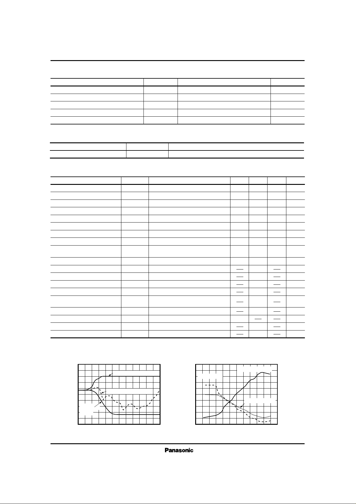
0
–10
–20
–30
–40
–50
–60
–70
–80
0 10 20 30 40 50 60 70 80 90 100 110 120
V
O
(dB)
Vin (dBµ)
Output Voltage, AMR –V
in
5
4
3
2
1
0
0 10 20 30 40 50 60 70 80 90 100 110 120
V
cont
(dB)
Vin (dBµ)
Control Voltage – V
in
SD Output Pin4
FM 1kHz, 30% Modulation
AM 1kHz, 30% Modulation
Mute Voltage Pin3
Control Voltage Pin2
0% Modulation
(Noise)
■ Characteristics Curve
 Loading...