

Panasonic AN7223 Datasheet
ICs for FM/AM Tuner
■ Overview
The AN7223 is an IC designed for high-class radio cas-
sette recorder with multifunctioned FM/AM IF system.
■ Features
•
Wide operating supply voltage range : VCC= 2.8V~12V
•
Incorporating both FM and AM detectors
•
Incorporating a level indicator output
(FM/AM common use)
•
AM : High sensitivity,including RF amplifier
•
Low power consumption
•
Muting control
•
AFC control
•
Fewer external parts
•
High stability on both AM and FM
•
Low shock noise level from function switch operation
•
SW band available (f= 30MHz)
AN7223
AM Tuner, FM/AM IF Amplifier Circuit for Radio Cassette Recorder
1
2
3
4
5
6
7
8
9
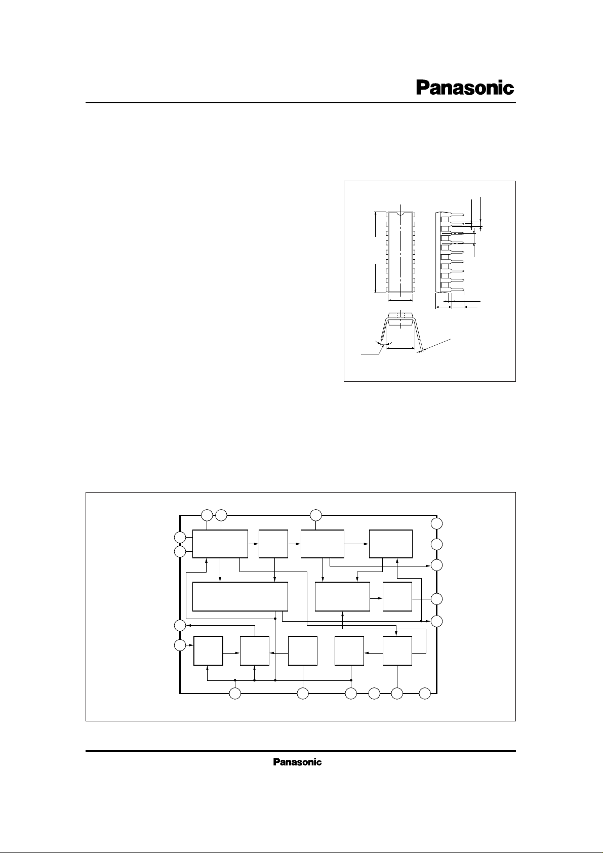
21.7±0.3
1.2±0.25
3 ~ 15˚
Unit : mm
6.3
±
0.25
0.5±0.1
2.54
18-Lead DIP Package (DIP018-P-0300E)
(3.45)
7.62±0.25
0.3
+ 0.1
– 0.25
18
17
16
15
14
13
12
11
10
0.51min.
3.8±0.25
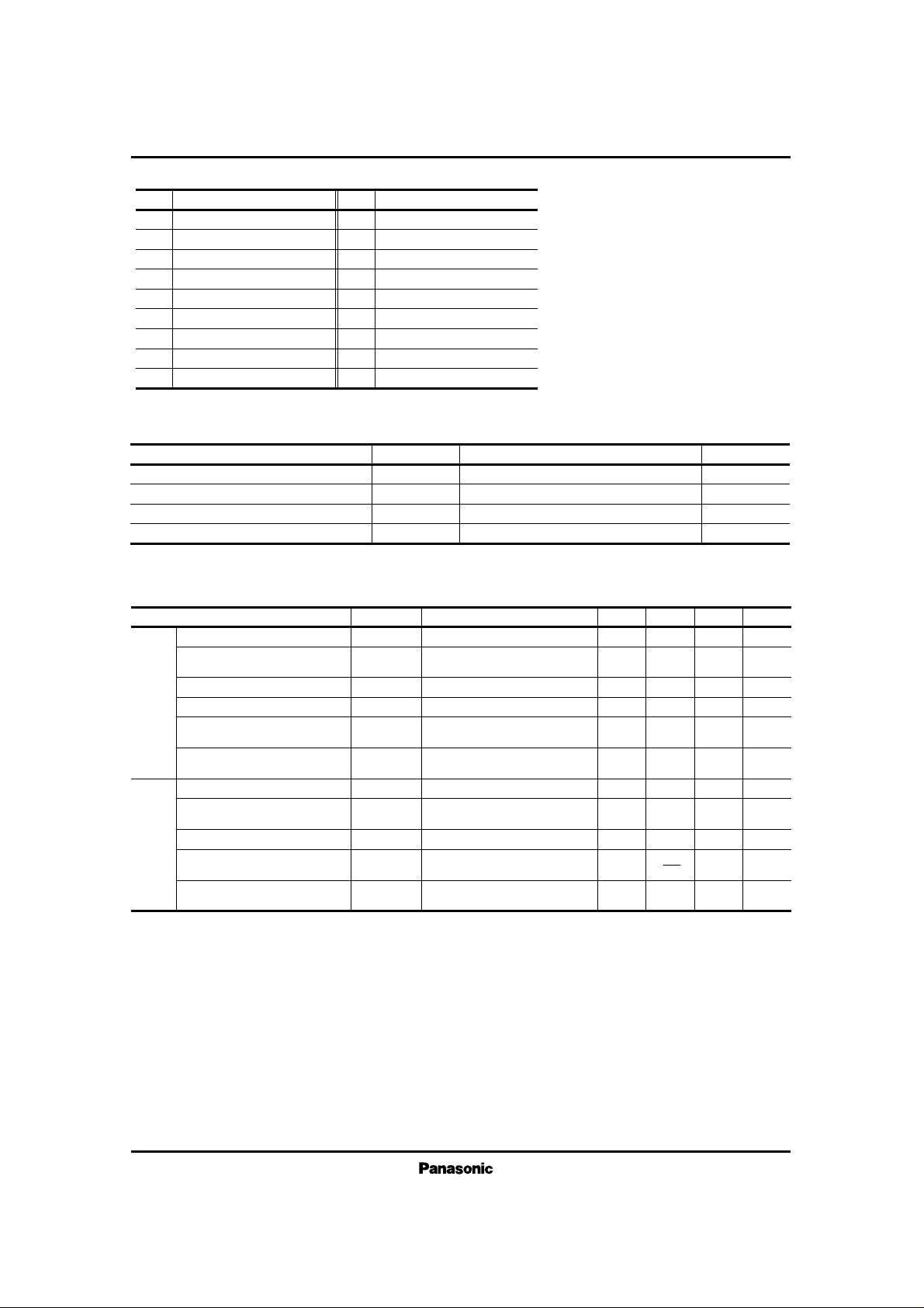
■ Block Diagram
8 9 12
1
AM/FM
IF Amp.
7
Level Meter
4
3
AM RF
Amp.
5 18 6 2 10 11
AM
Mixer
FM IF
Amp.
AM
L Osc.
FM
Quad. Det.
Mute or
Shock Noise
Canceller
AGC
Mute Det.
AM)
CC (
AF
Amp.
AM
Det.
14
V
CC
17
16
13
15
GNDV
ICs for FM/AM Tuner
AN7223
Pin No.
Pin Name
1
2
3
4
5
6
7
8
9
FM IF Amp. Input
V
CC
(AM)
AM RF Amp. Input
AM Mixer Output
AGC Output (2)
AGC Output (1)
AM IF Amp. Input
IF By-pass
IF By-pass
■ Pin Descriptions
Pin No.
Pin Name
10
11
12
13
14
15
16
17
18
AM Detection Output
GND
FM Detector Coil
AF Output
V
CC
Level Meter Output
AFC Output
Reference Voltage
Local Oscillation
V
CC
P
D
T
opr
T
stg
Supply Voltage
Power Dissipation
Operating Ambient Temperature
Storage Temperature
V
mW
˚C
˚C
Parameter Symbol Rating Unit
14.4
317
–20 ~ + 75
–55 ~ + 150
■ Absolute Maximum Ratings (Ta=25˚C)
Vi= 80dBµ, f=10.7MHz,
f
dev.
= 22.5kHz, fm= 400Hz
Input at υO= –3dB
Input at υ
O
= less than –20dB
Vi= 50dBµ, f=10.7MHz,
f
dev.
= 22.5kHz, fm= 400Hz
V
i
= 80dBµ, f= 10.7MHz,
f
dev.
= 22.5kHz, fm= 400Hz
Vi= 80dBµ, f= 1MHz,
Mod.= 30%, f
m
= 400Hz
Input at υ
O
= 10mV
Vi= –10dBµ, f= 1MHz,
Mod.= 30%, f
m
= 400Hz
Vi= 80dBµ, f= 1MHz,
Mod.= 30%, f
m
= 400Hz
Parameter Symbol Condition min. typ. max. Unit
Total Circuit Current
Demodulation Output Level
Limiting Sensitivity
Muting Sensitivity
Signal Meter Driving
Output 1
Signal Meter Driving
Output 2
Total Circuit Current
Detection Output Level
Max.Sensitivity
Signal Meter Driving
Output 1
Signal Meter Driving
Output 2
I
tot
υ
O (FM)
V
i (lim)
Vi
(mute)
V
15
V
15
I
tot
υ
O (AM)
S
max.
V
15
V
15
9
75
41.5
45
120
1.14
8
60
4.5
0
1.12
FM
AM
mA
mV
dBµ
dBµ
mV
V
mA
mV
dBµ
mV
V
(DC measurement)
(DC measurement)
14
100
44.5
50
600
1.26
13
80
9.5
1.25
20
125
47.5
59
1150
1.42
19
100
12.5
130
1.38
■ Electrical Characteristics (V
CC
=5V, Ta= 25˚C)
 Loading...