

Panasonic AJ-D400P User Manual
Digital Camera/VTR
Operating Instructions
PAJ-
Printed in Japan
VQT7984-1 F1298H2059-100
P
D
For your safety
CAUTION
RISK OF ELECTRIC SHOCK
DO NOT OPEN
CAUTION: TO REDUCE THE RISK OF ELECTRIC SHOCK,
REFER SERVICING TO QUALIFIED SERVICE PERSONNEL.
ATTENTION:
The product you have purchased is powered by a
nickel cadmium battery which is recyclable. At
the end of it’s useful life, under various state and
local laws, it is illegal to dispose of this battery
into your municipal waste stream.
Please call 1-800-8-BATTERY for information on
how to recycle this battery.
Memory Back-up Battery
Replace battery with part No. CR2032 only.
Use of another battery may present a risk of fire
or explosion.
Caution—Battery may explode if mistreated.
Do not recharge, disassemble or dispose of in
fire.
DO NOT REMOVE COVER (OR BACK).
NO USER-SERVICEABLE PARTS INSIDE.
The lightning flash with arrowhead symbol,
within an equilateral triangle, is intended to alert
the user to the presence of uninsulated “dangerous voltage” within the product’s enclosure
that may be of sufficient magnitude to constitute a risk of electric shock to persons.
The exclamation point within an equilateral triangle is intended to alert the user to the presence of important operating and maintenance
(service) instructions in the literature accompanying the appliance.
RBRC
RBRC
Ni-Cd
FCC NOTE:
This device complies with Part 15 of the FCC
Rules. To assure continued compliance follow
the attached installation instructions and do not
make any unauthorized modifications.
This equipment has been tested and found to
comply with the limits for a Class A digital device,
pursuant to Part 15 of the FCC Rules. These limits are designed to provide reasonable protection
against harmful interference when the equipment
is operated in a commercial environment. This
equipment generates, uses, and can radiate radio frequency energy and, if not installed and
used in accordance with the instruction manual,
may cause harmful interference to radio communications. Operation of this equipment in a residential area is likely to cause harmful interference
in which case the user will be required to correct
the interference at his own expense.
CAUTION:
TO REDUCE THE RISK OF FIRE OR
SHOCK HAZARD AND ANNOYING INTERFERENCE, USE THE RECOMMENDED
ACCESSORIES ONLY.
WARNING:
TO REDUCE THE RISK OF FIRE OR
SHOCK HAZARD, DO NOT EXPOSE THIS
EQUIPMENT TO RAIN OR MOISTURE.
CAUTION:
TO REDUCE THE RISK OF FIRE OR
SHOCK HAZARD, REFER MOUNTING OF
THE OPTIONAL BOARD TO AUTHORIZED SERVICE PERSONNEL.
is the safety information.
–2–

Contents
Safety Precautions . . . . . . . . . . . . . . . . 2
General and Features . . . . . . . . . . . . . . 5
ÁFeatures of the Camera Section. . . . . 5
ÁFeatures of the VTR Section . . . . . . . 8
ÁSystem Configuration . . . . . . . . . . . . . 9
Controls and Their Functions
ÁPower Supply Section. . . . . . . . . . . . . 10
ÁAccessory Mounting Section . . . . . . . 11
ÁAudio Function Section . . . . . . . . . . . . 12
ÁShooting (Recording)/Playback
Function Section . . . . . . . . . . . . . . . . . 14
ÁMenu Operation Section . . . . . . . . . . . 20
ÁTime Code-Related Section . . . . . . . . 20
ÁWarning/Status Display Section . . . . . 22
Power Supply
ÁUsing an Anton Bauer Battery
Pack . . . . . . . . . . . . . . . . . . . . . . . . . . 23
ÁUsing the Panasonic AU-BP402
Battery Pack . . . . . . . . . . . . . . . . . . . . 24
ÁUsing a Sony Battery Pack . . . . . . . . . 26
ÁUsing the Sony BP-90 Battery
Pack . . . . . . . . . . . . . . . . . . . . . . . . . . 27
ÁUsing an AC Power Supply (When
Using the AJ-B75 AC Adaptor) . . . . . . 28
Mounting the Lens . . . . . . . . . . . . . . . 29
Adjusting the Lens Flange . . . . . . . . . 30
Adjusting the White Shading . . . . . . . 31
Adjusting the Viewfinder
ÁAdjusting the Position . . . . . . . . . . . . . 33
ÁAdjusting the Diopter and
Screen . . . . . . . . . . . . . . . . . . . . . . . . 34
ÁAdjusting the Eyecup Position . . . . . . 34
ÁDetaching the Eyecup. . . . . . . . . . . . . 35
ÁDetaching and Mounting the
Viewfinder . . . . . . . . . . . . . . . . . . . . . . 36
ÁUsing the Microphone Kit
(Standard accessory) Mounted
to the Main Unit. . . . . . . . . . . . . . . . . . 37
ÁMounting the AJ-MH700P Microphone
Holder (Option) . . . . . . . . . . . . . . . . . . 38
ÁUsing the Microphone not Mounted to
the Main Unit. . . . . . . . . . . . . . . . . . . . 39
ÁMounting a Wireless Microphone . . . . 40
Connecting an Audio Component . . . . . 40
Mounting the Unit to a Tripod . . . . . . . . 41
Adjusting the Shoulder Pad Position. . . 42
Attaching the Rain Cover . . . . . . . . . . . 43
Connecting the AQ-EC1 Extension
Control Unit (Option) . . . . . . . . . . . . . 44
Warning/Status Displays in the
Viewfinder and Display Window
ÁDisplaying the Setting Menu Inside the
Viewfinder . . . . . . . . . . . . . . . . . . . . . . 45
ÁSetting Menu Configuration . . . . . . . . 45
ÁBasic Setting Menu Operations . . . . . 47
Lamp Displays Inside the
Viewfinder . . . . . . . . . . . . . . . . . . . . . 49
ÁSetting the ! Lamp Display . . . . . . . . . 50
Status Displays Inside the Viewfinder
Screen . . . . . . . . . . . . . . . . . . . . . . . . 51
ÁSelecting Display Items. . . . . . . . . . . . 54
ÁDisplay Mode and Setting Change
Message . . . . . . . . . . . . . . . . . . . . . . . 55
ÁChanging the Display Mode . . . . . . . . 56
ÁSetting the Marker Displays . . . . . . . . 56
ÁSetting the Camera ID . . . . . . . . . . . . 57
Audio Input Preparations
ÁUsing the Microphone Mounted to the
Main Unit. . . . . . . . . . . . . . . . . . . . . . . 37
Bold letters should be set or adjusted immediately after
purchase.
–3–

Contents
Displays
ÁRemaining Battery Level and Audio
Level Displays. . . . . . . . . . . . . . . . . . . 58
ÁVTR Section Operation/Status-Related
Displays . . . . . . . . . . . . . . . . . . . . . . . 58
ÁTime Code-Related Displays . . . . . . . 59
Adjusting the Time and Date . . . . . . . . . 60
Adjustments and Setup During Recording
ÁAdjustments and Setup using the Setting
Menu. . . . . . . . . . . . . . . . . . . . . . . . . . 61
ÁSetting the Gain Selector Value . . . . . 62
ÁSelecting Functions . . . . . . . . . . . . . . 63
Adjusting the White Balance/Black Balance
ÁAdjusting the White Balance . . . . . . . . 64
ÁAdjusting the Black Balance . . . . . . . . 67
Setting the Electronic Shutter
ÁShutter Modes . . . . . . . . . . . . . . . . . . 69
ÁSelecting the Shutter Mode/Speed . . . 70
ÁSetting the Synchro Scan Mode . . . . . 71
ÁChanging the Shutter Speed/Mode
Selection Range . . . . . . . . . . . . . . . . . 72
Changing the Iris Automatic Adjustment
Reference Value . . . . . . . . . . . . . . . . 72
Adjusting the Audio Level . . . . . . . . . . . 73
Playback —Checking Recorded Contents
ÁRec Review. . . . . . . . . . . . . . . . . . . . . 86
ÁColor Playback . . . . . . . . . . . . . . . . . . 86
Connection With an External VTR. . . . . 87
Recording Simultaneously with the
Internal VTR and an External
VTR . . . . . . . . . . . . . . . . . . . . . . . . . . 88
Recording With an External VTR Instead
of the Internal VTR
ÁUsing the 26-pin Output Adaptor . . . . 90
RET Button . . . . . . . . . . . . . . . . . . . . . . 92
Replacing the Backup Battery . . . . . . . . 93
Setting Menu Screens . . . . . . . . . . . . . . 94
Warning System . . . . . . . . . . . . . . . . . . 116
Emergency Eject . . . . . . . . . . . . . . . . . . 118
Error Codes. . . . . . . . . . . . . . . . . . . . . . 118
Maintenance
ÁCondensation . . . . . . . . . . . . . . . . . . . 119
ÁCleaning the Video Heads . . . . . . . . . 119
ÁCleaning the Viewfinder . . . . . . . . . . . 119
ÁCharacteristic Phenomenon of CCD
Cameras . . . . . . . . . . . . . . . . . . . . . . . 119
Setting the Time Data
ÁSetting the Time Code . . . . . . . . . . . . 75
ÁSetting the User Bit. . . . . . . . . . . . . . . 76
ÁLocking the Time Code to an External
Source . . . . . . . . . . . . . . . . . . . . . . . . 77
ÁExternal Lock Operation
Procedure . . . . . . . . . . . . . . . . . . . . . . 78
Cassettes
ÁInserting and Ejecting Cassettes . . . . 79
ÁPreventing Accidental Erasure . . . . . . 80
Recording
ÁBasic Procedures . . . . . . . . . . . . . . . . 81
ÁSuccessive Shooting . . . . . . . . . . . . . 84
Inspections Before Shooting
ÁInspection Preparations . . . . . . . . . . . 120
ÁInspecting the Camera Section. . . . . . 120
ÁInspecting the Viewfinder . . . . . . . . . . 121
ÁInspecting the Iris and Zoom
Functions . . . . . . . . . . . . . . . . . . . . . . 122
ÁInspecting the VTR Section . . . . . . . . 122
Specifications
ÁGeneral . . . . . . . . . . . . . . . . . . . . . . . . 124
ÁCamera Section . . . . . . . . . . . . . . . . . 124
ÁViewfinder . . . . . . . . . . . . . . . . . . . . . . 124
ÁVTR Section . . . . . . . . . . . . . . . . . . . . 125
ÁAccessories . . . . . . . . . . . . . . . . . . . . 125
ÁRelated Components . . . . . . . . . . . . . 126
–4–

General and Features
The model AJ-D400 integrates a color video camera which employs three frame interline transfer (FIT) CCDs with 410,000 device on-chip lenses with a DVCPRO format VTR which is
equipped with the latest compression technology.
The AJ-D400 is particularly compact and light weight with low power consumption, and realizes
the optimal functions and performance for an electronic news gathering (ENG) VTR-integrated
camera such as high picture quality and sensitivity, mobility, dustproofing and dampproofing,
etc. In addition, both the camera section and the VTR employ a digital signal processing system
which further improves picture quality.
Features of the Camera Section
The camera section of the AJ-D400 has the following features.
ÁHigh sensitivity: 2000 lux (F8)
ÁHigh S/N ratio: 62 dB (standard)
ÁUltra-low smear
ÁUltra-low flare
Digital signal processing
Signal processing is digitized by a 14.3 MHz/28.6 MHz (typ.) 10-bit AD/DA converter. This improves picture quality, stability and reliability, and allows the viewfinder screen displays as well
as numerous adjustment and setup items to be converted to menus.
Setting menu
The setting menu is displayed on the viewfinder screen, and controls the status displays, messages, marker displays, etc. Whether or not to display each item, as well as the display conditions when items are to be displayed, can be selected according to the user’s convenience. For
example, display ON/OFF for the ! lamp display which informs the user that the unit has entered
irregular status can be selected for 7 different conditions.
The setting menu is also used to select various settings and functions.
High-function electronic shutter
Using the built-in electronic shutter achieves steady images even of quickly moving subjects. In
addition, the following special operation modes can also be selected.
ÁSynchro scan mode: This mode is suited for shooting personal computer and workstation mon-
itor screens, and provides images with little horizontal stripe noise.
ÁHigh vertical resolution (Super V) mode: This mode provides images with high vertical resolu-
tion compared to standard mode.
Wide range of video gain selections
Eleven gain values can be selected from p3 dB to o30 dB using the setting menu and the GAIN
switch. The high S/N ratio allows images with little noise to be obtained even when the gain is
increased for shooting in dark locations.
Automatic adjustment and memory functions for black balance/white balance
The black set, black balance and white balance can be automatically adjusted by simple switch
operations. Adjustment values are held in the memory even if the power for the unit is turned off,
so there is no need to readjust the balance each time the power is turned on.
There are two memory systems for white balance which can hold four adjustment values each
for the CC and ND filters, making a total of eight adjustment values. When adjustment values
matching the illumination conditions are selected from among the values stored in the memory,
the unit is automatically adjusted to the corresponding white balance. (A menu setting also allows adjustment of only two values instead of the values for each filter.) In addition, when the
unit is shipped from the factory, the white balance value for 3200K is stored in the memory as a
preset value. This value can be called when there is no time to adjust the white balance, etc.
–5–

Features
High-performance viewfinder
ÁThe high-resolution CRT projects a detailed picture which facilitates focus operations.
ÁThe viewfinder employs a low flare CRT which makes the screen easy to see.
ÁA center marker which indicates the center of the screen and a safety zone marker which indi-
cates the effective screen region can be displayed by menu operations.
ÁA large aperture allows the screen to be easily seen even when the operator’s eye is removed
from the eyepiece.
ÁThe eyepiece can easily be detached. When the eyepiece is detached, the center of the
screen will not become blurred even when viewed from a distance.
ÁOne-touch position adjustment is possible not only in the right-left direction but also in the
forward-backward direction.
Character display function
The unit is equipped with a function that displays switch settings, the automatic adjustment status for black balance and white balance, warning displays, etc. on the viewfinder screen.
In addition, when using an Anton Bauer Digital Magnum series battery as the unit’s power supply, the remaining battery level can be displayed numerically on the viewfinder screen.
Warning system for displaying the VTR section status
The unit informs of VTR trouble, the end of the tape, battery wear, etc. with various warning
lamps and a warning tone. The remaining tape time can also be checked by the character display inside the viewfinder.
Four filter disks as standard equipment
CC (color temperature conversion) and ND (neutral density) filters are provided as standard
equipment. This allows the optimal filter setting to be selected from among four combinations in
accordance with the brightness of the subject.
Fine adjustment of the automatic iris reference value
The reference value for automatic iris adjustment can be finely adjusted by setting menu operations.
Auto close function
The unit is equipped with an auto close function which automatically closes the lens in the following cases.
ÁWhen the black balance is automatically adjusted.
ÁWhen the power is turned off in the auto iris mode.
Generation of SMPTE color bar and reference audio signals
The camera section contains a circuit which generates an SMPTE type color bar signal to facilitate color monitor adjustments, and a circuit which generates a reference level audio signal to
facilitate audio level adjustments.
Functions and circuits for assuring high picture quality
The AJ-D400 is equipped with the following functions (and circuits) in order to assure high picture quality and is designed to make the fullest use of the advantages of the high-performance
CCD.
ÁA built-in AUTO KNEE circuit achieves a wide dynamic range which allows large signals to
pass through.
ÁA built-in 2-line image enhancer
ÁA built-in shading compensation function for use with a lens extender
ÁA built-in sawtooth wave generator for adjustments
ÁA zebra pattern ON/OFF selector switch which selects three types of zebra patterns including
spot zebra from two levels of zebra patterns.
Audio functions
ÁA phantom power supply type super-cardioid microphone (standard accessory) can be at-
tached and it can also be detached from the main unit for use in interviews.
ÁMicrophone can also be connected, and can be attached to the main unit using the
AJ-MH700P microphone holder (option).
ÁThe audio CH1 recording level can be easily adjusted at the front panel of the unit.
–6–

Features
Recording by an external VTR
When an external VTR is connected using the 26-pin output adaptor (option, AJ-YA900P or
AJ-YA700P), recording can be performed by the external VTR instead of the internal VTR.
Remote control
Connecting the Extension Control Unit (option, AQ-EC1) allows a portion of the camera section
functions to be operated by remote control.
–7–

Features
Features of the VTR section
Digital system
The VTR section features a component digital recording system that employs the latest compression technology and non-compressed PCM recording for audio. This system provides superior S/N, frequency band and waveform characteristics as well as reproduction of detailed areas,
etc., and realizes even higher picture and sound quality.
Rec review function
This function automatically rewinds the tape and plays back the last two seconds recorded, allowing recorded contents to be quickly checked.
Playback function
Playback pictures (black-and-white pictures) can be seen on the viewfinder screen. In addition,
color playback pictures can be seen on a color monitor connected to the VIDEO OUT connector
on the main unit.
Built-in time code generator/reader
Time code information can be recorded and played back on a dedicated subcode track.
Locking of the time code to an external source
The built-in time code generator can be locked to an external generator. Also, the built-in time
code generator uses a lithium battery as its back-up power supply, allowing time codes to be
backed up for approximately one year even if power is not supplied to the unit.
Built-in DOLBY NR SystemF
A Dolby B Noise Reduction System is built in for audio recording in the longitudinal direction.
Successive shooting
Images can be shot successively within an accuracy of 0po1 frame simply by pressing the VTR
START button or the lens VTR button.
FDolby noise reduction manufactured under license from Dolby Laboratories Licensing Corporation.
“Dolby” and the double-D symbol 0 are trademarks of Dolby Laboratories Licensing Corporation.
–8–
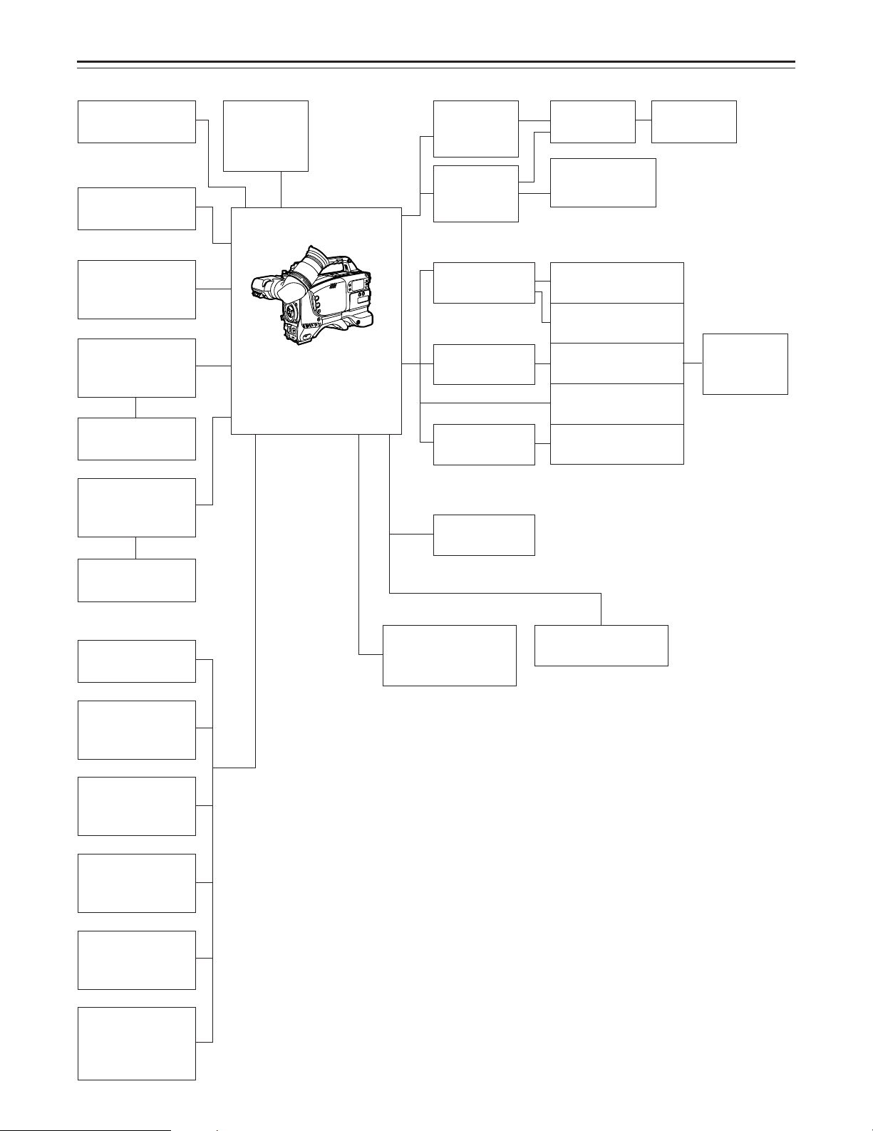
System Configuration
Microphone kit
(supplied)
Microphone holder
AJ-MH700P
Lens
(Bayonet type)
Fujinon/Canon
5w EVF mount
adaptor
AJ-QVF900
5w EVF AJ-VF53
5w EVF mount
adaptor
AJ-YA711
Wireless
microphone
receiver
WX-RA700
Camera/VTR
AJ-D400
26P output
adaptor
AJ-YA700P
26P/12P output
adaptor
AJ-YA900P
Battery case
SHAN-B220
Battery case
AU-M402H
Battery case
AC adaptor
AJ-B75
VTR cable VTR
Multi connector
cable
SHAN-C12TCA
Panasonic Battery
AU-BP220
Sony Battery
NP-1
Panasonic Battery
AU-BP402
Anton Bauer Battery
Sony Battery
BP-90
Battery
charger
AG-B425
5w EVF
WV-VF65B/C
Rain cover
SHAN-RC700
Soft carrying
case
AJ-SC900
Tripod attachment
(supplied)
Extension control
unit
AQ-EC1
Carrying case
SHAN-B700
Cassette tape
ÁM size cassette tape
exclusively for
DVCPRO
Cleaning tape
AJ-CL12MP
Time code input/
output/video input
adaptor
AJ-YA710P
–9–
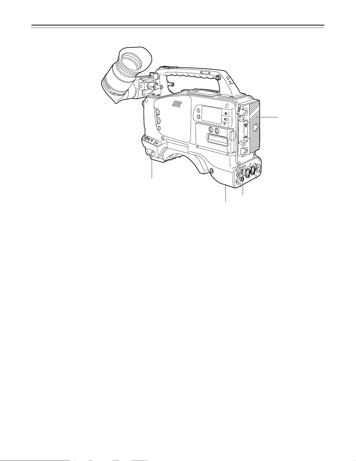
Controls and Their Functions
4
1
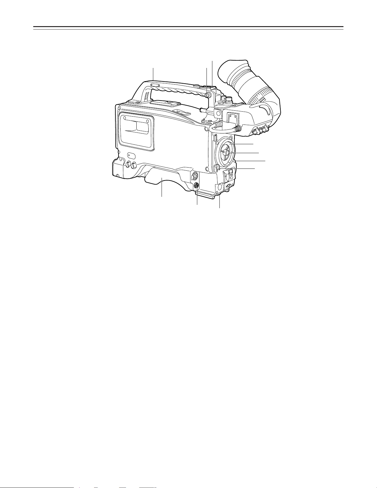
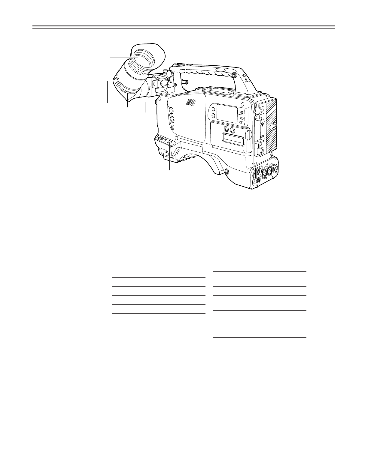
Power Supply Section
e Battery holder
The battery pack (option) made by Anton Bauer is mounted onto this holder.
f DC IN (external power input) connector (XLR, 4P)
The AJ-B75 AC adaptor (option) is plugged into this socket when the unit is to be operated by
AC power. An external battery is plugged in when an external battery is to be used to operate
the unit.
g BREAKER (circuit breaker) button
In order to protect the equipment, the circuit breaker is tripped and the power is automatically
turned off when an excessively high level of power flows inside. Upon completion of the internal inspection and adjustments, push this button back in. The power will come back on provided that there is no trouble inside the unit.
h POWER switch
ON: Set to this position to turn on the unit’s power.
OFF: Set to this position to turn off the unit’s power.
2
3
–10–
Controls and Their Functions
5
6
5
7
9
8
n
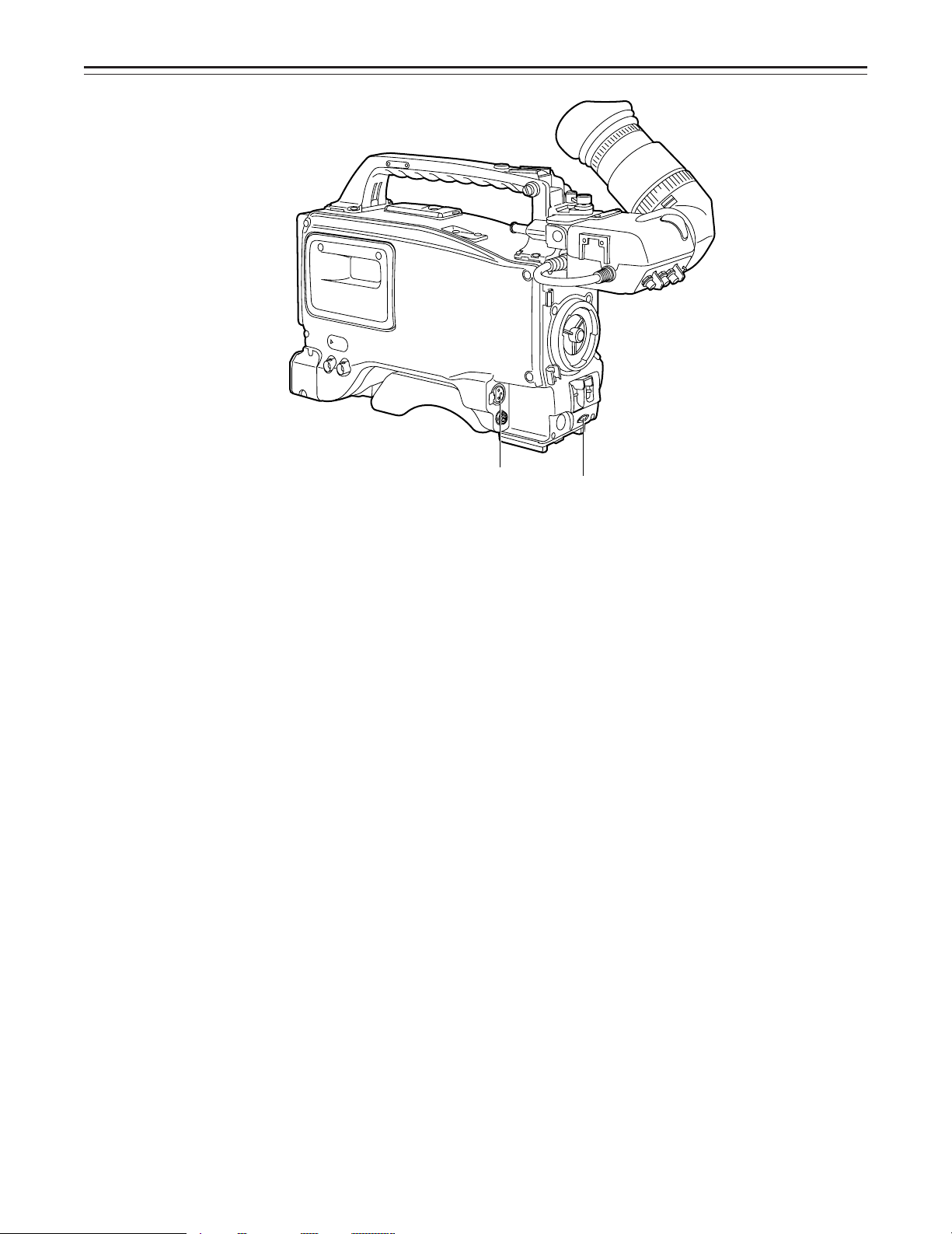
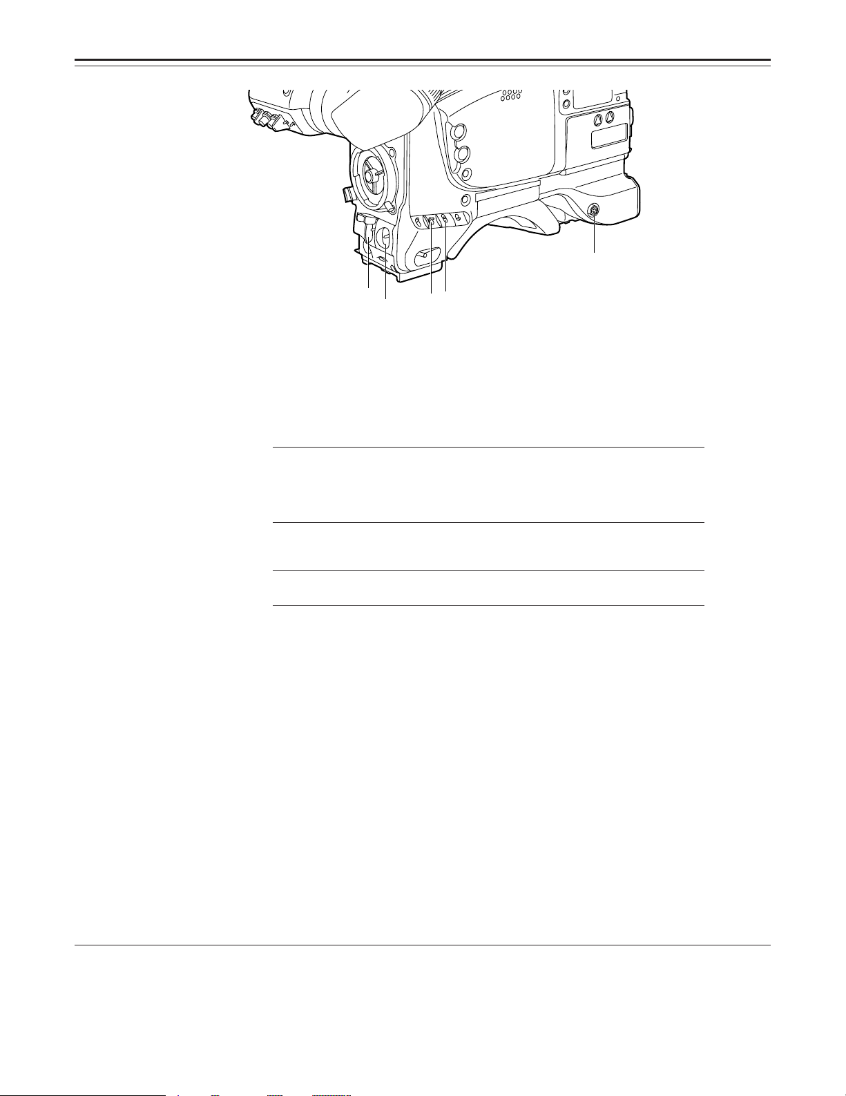
Accessory Mounting Section
i Hook for mounting shoulder belt
Attach the accessory shoulder belt to this hook.
j Light shoe
Mount the video light, etc. onto this shoe.
k Lens mount (bayonet type)
Mount the lens here.
l Lens clamping lever
Insert the lens into the lens mount k, and turn the lens mount ring using this lever to clamp
the lens.
m Lens mount cap
Press up the lens clamping lever l to remove this cap. Keep the cap in place if the lens is
not going to be mounted.
n Lens cable clamp
This is for clamping the lens cable.
o Tripod mount
When the unit is to be secured to a tripod, mount the optional tripod attachment.
p LENS connector (12-pin)
Hook up the lens connecting cable to this connector. Consult with your dealer concerning the
lens which you are going to use.
q Shoulder pad
Adjust this pad to facilitate operation when carrying the unit on your shoulder. Its position can
be brought forward or backward and adjusted by loosening the two set screws.
q
p
o
–11–
Controls and Their Functions
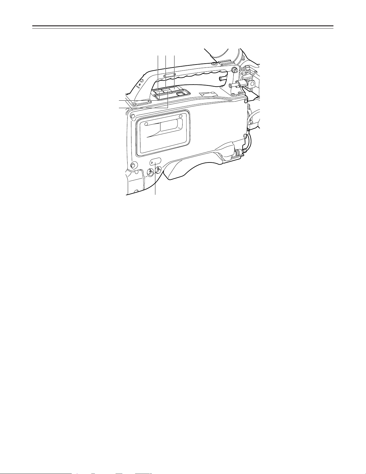
Audio Function Section (1)
r AUDIO LEVEL CH1 (audio channel 1 recording level) control
When the AUDIO SELECT CH1/CH2 switch u is set to MAN, the recording level of audio
channel 1 can be adjusted by this control in addition to the AUDIO LEVEL CH1 control t on
the side panel.
s MIC IN (microphone input) jack (XLR, 3-pin)
Connect an optional microphone to this jack. The power for the microphone is supplied from
this jack.
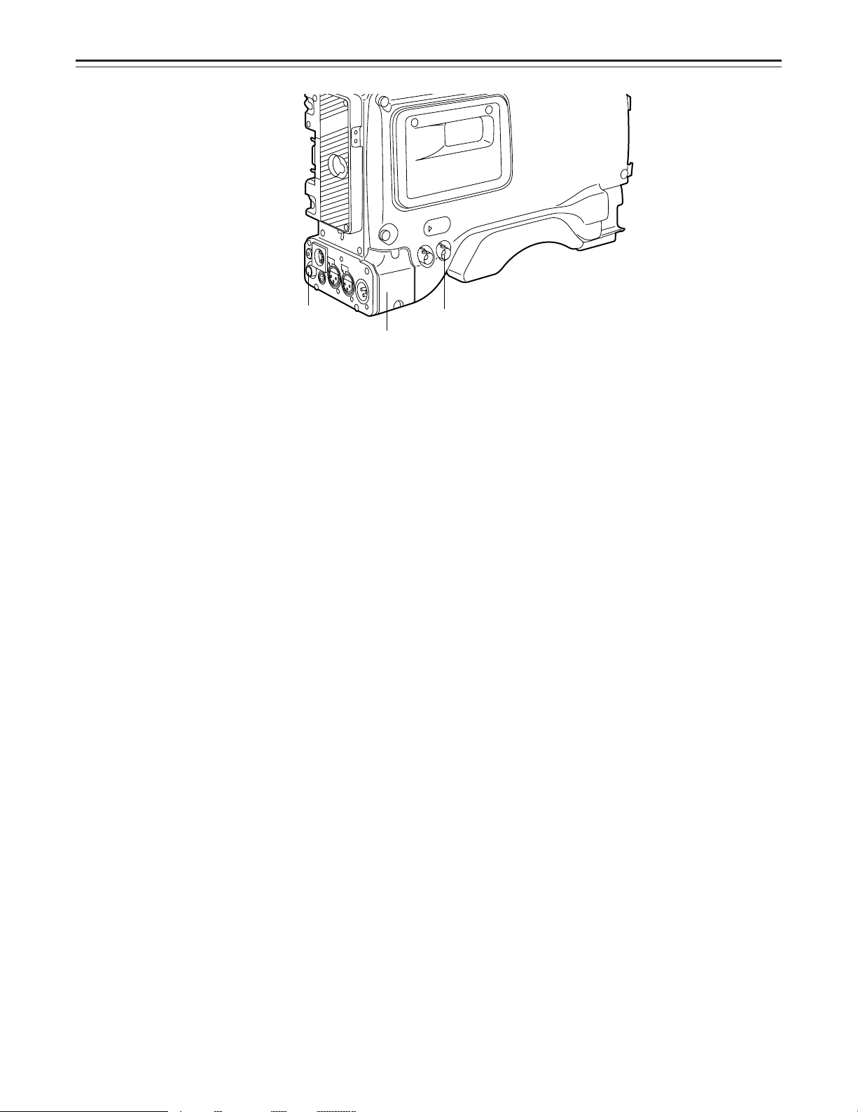
Audio Function Section (2)
t AUDIO LEVEL CH1/CH2 (audio channel 1/2 recording level) controls
When the AUDIO SELECT CH1/CH2 switch u is set to MAN, the audio level of audio channels 1 and 2 can be adjusted using these controls.
However, the audio CH1 level can also be adjusted using the AUDIO LEVEL CH1 control r
on the front panel.
u AUDIO SELECT CH1/CH2 switch (audio channel 1/2 auto/manual level adjustment se-
lector) switch
This selects the method used to adjust the audio levels of audio channels 1 and 2.
AUTO: For adjusting the levels automatically.
MAN: For adjusting the levels manually.
v AUDIO IN (audio input selector) switch
This selects the input signals to be recorded on audio channels 1 and 2.
FRONT [MIC]: The microphone input signals connected to the MIC IN jack s are recorded.
REAR [MIC]: The microphone input signals connected to the AUDIO IN CH1/CH2 connec-
REAR [LINE]: The line input signals connected to the AUDIO IN CH1/CH2 connectors w
w AUDIO IN CH1/CH2 (audio input channel 1/2) connectors (XLR, 3P)
An audio component or microphone is connected here.
x AUDIO OUT connector (XLR, 3P)
This is connected to an audio component. The audio channels can be selected on the setting
menu.
y DC OUT (DC power output) connector
This is the DC 12 V output connector. A current of approximately 100 mA can be taken out.
s
tors w are recorded.
are recorded.
r
–12–
Controls and Their Functions
z
{
|
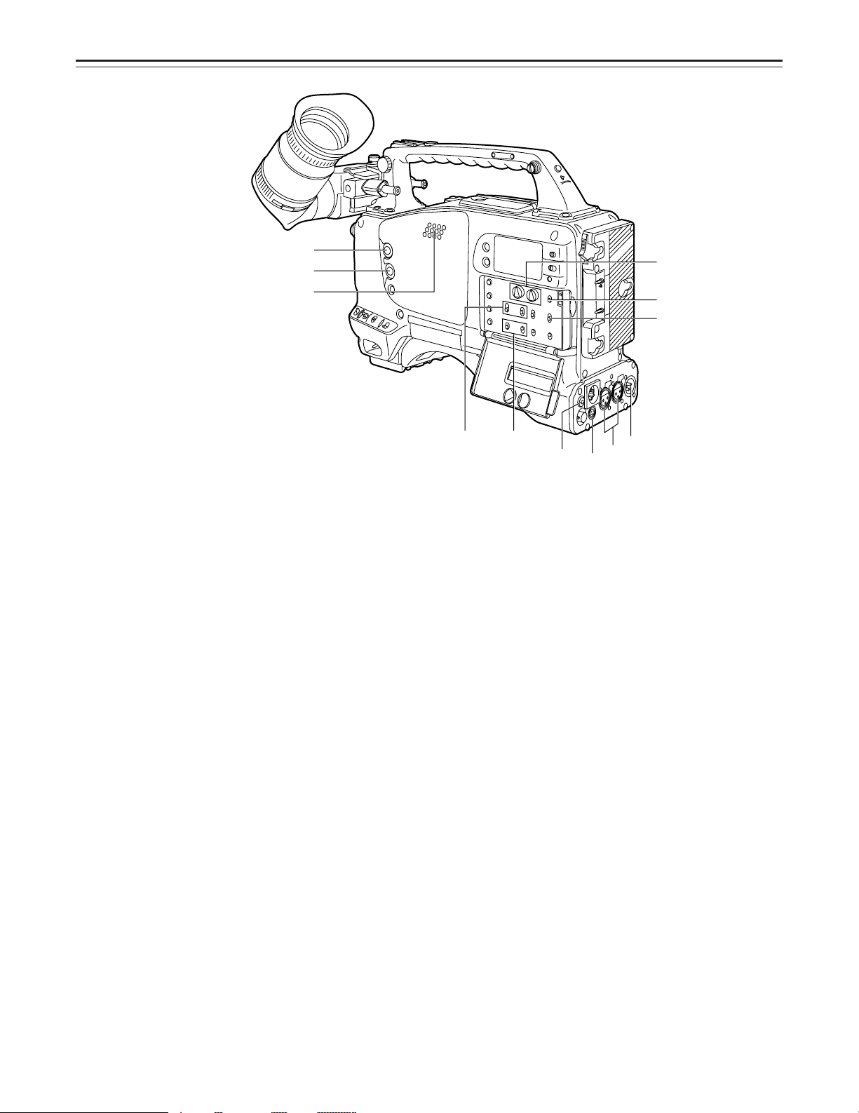
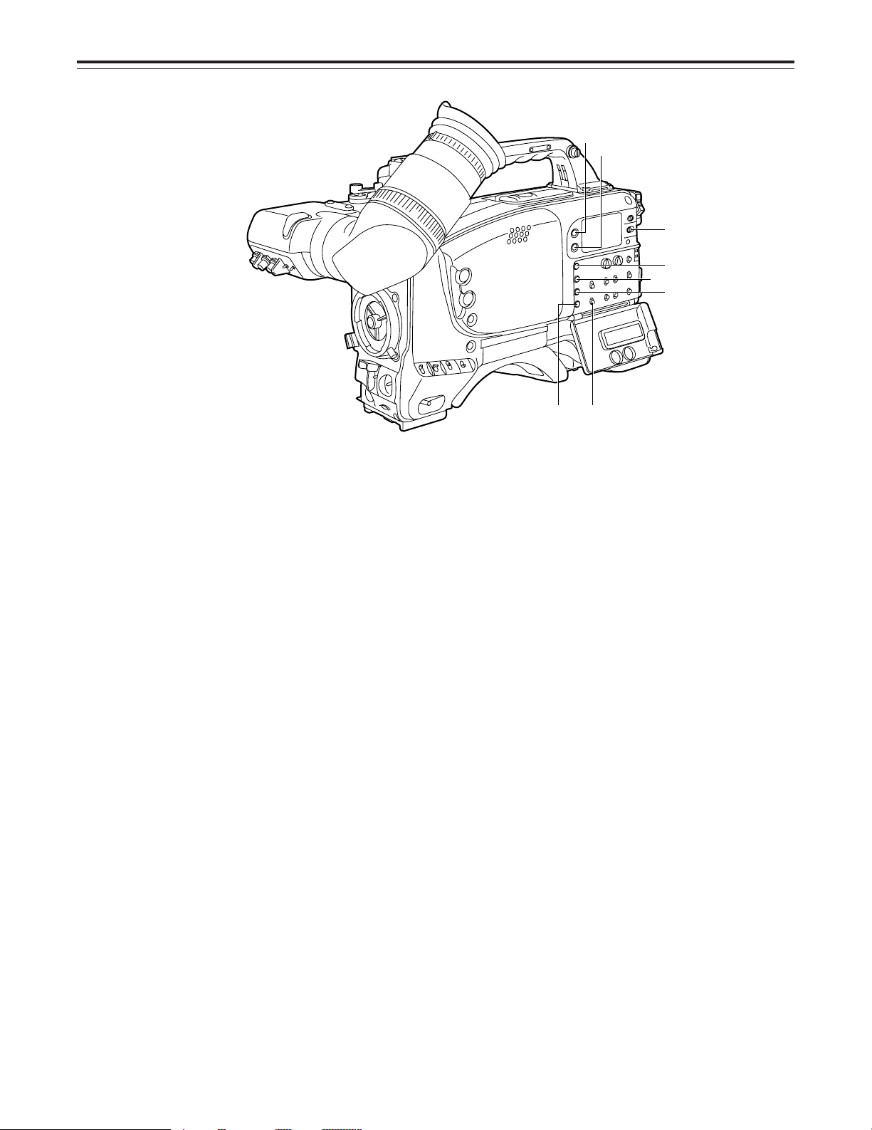
Audio Function Section (3)
z ALARM (warning tone volume) control
This adjusts the warning tone volume heard from the speaker | or the earphone connected
to the PHONES jack . When it is set to the lowest position, the warning tone is not audible.
However, by making changes to the inside parts, the tone can be made audible even when
the control is at its lowest position.
{ MONITOR (volume) control
This adjusts the volume of the sound other than the warning tone—the sound from the
speaker | or earphone . When it is set to the lowest position, no sound is heard.
Audio Function Section (4)
| Speaker
During recording, the EE sound can be monitored; during playback, the playback sound can
be monitored.
The warning tone is heard through the speaker in synchronization with the flashing or lighting
of the warning lamp and warning display.
The speaker sound is automatically muted when an earphone is connected to the PHONES
jack .
} MONITOR SELECT (audio channel selector) switch
This selects the audio channel whose sound is to be heard through the speaker | or earphone.
CH1: The audio channel 1 sound is output.
CH1, 2: The sound produced by mixing the audio channel 1 and 2 sound or the stereo
sound is output. However, only the mixed sound is output from the speaker |.
CH2: The audio channel 2 sound is output.
~ MONITOR (sound selector) switch
This selects the sound of the earphone when CH1, 2 is selected with the MONITOR SELECT
switch }.
ST: The stereo sound of audio channel 1 and 2 is output.
MIX: The mixed sound of audio channel 1 and 2 is output.
PHONES (earphone) jack (mini-jack)
When an earphone (option) is connected to this jack, the sound selected by the MONITOR
switch ~ can be heard. The warning tones relating to the unit’s operation or status can also
be heard. An earphone enabling a sufficiently high volume of sound to be heard is recommended.
When the earphone is connected, speaker | sound is automatically muted.
–13–
t
~
}
uv
ü
y
w
x
Controls and Their Functions
ß
†
°
§
¢
£
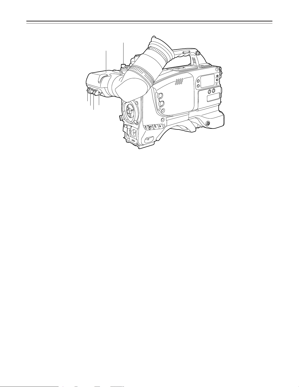
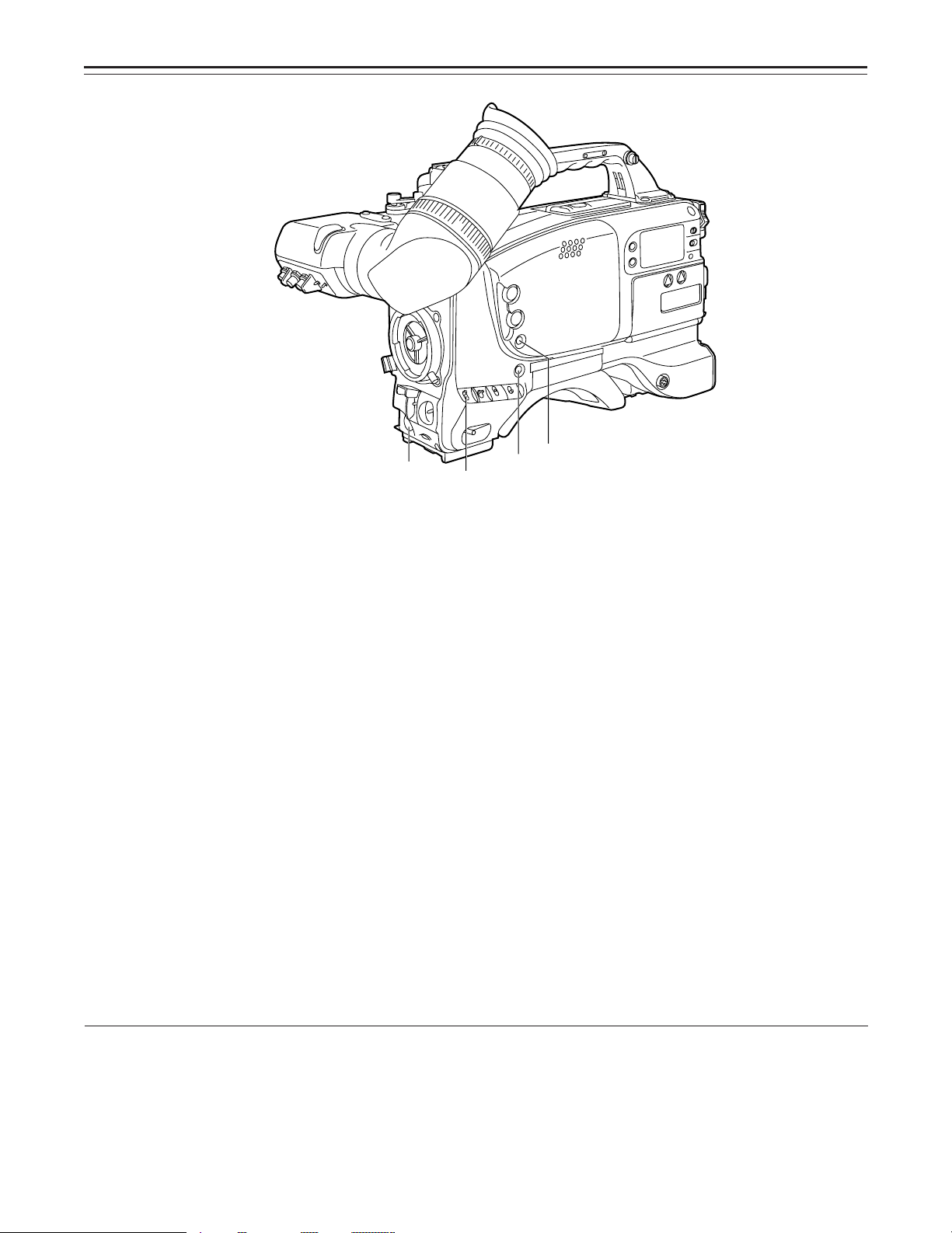
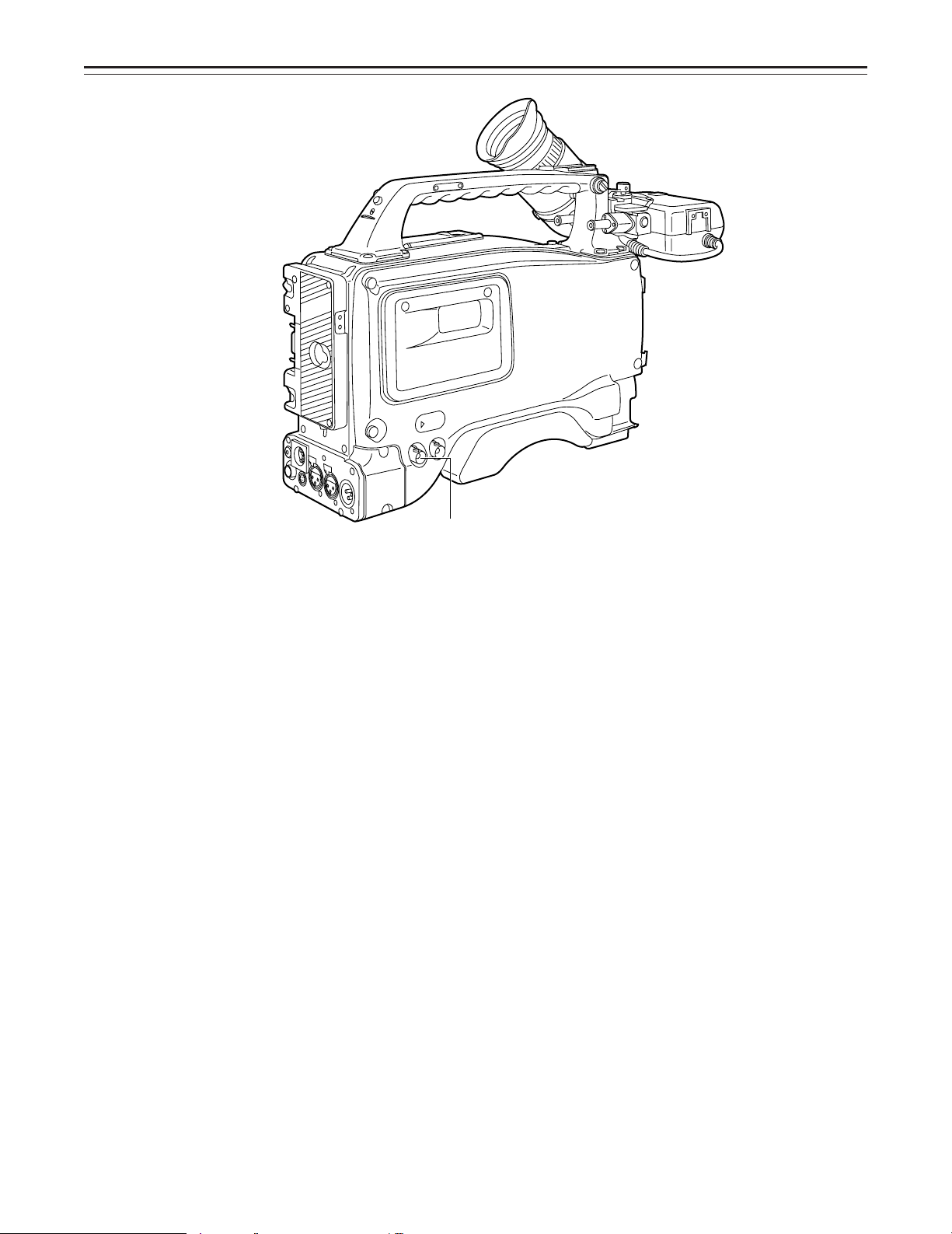
Shooting (Recording)/Playback Function Section (1)
Viewfinder
Black-and-white images can be seen in the viewfinder during recording and playback. Warnings and messages relating to the unit’s operating status and settings, zebra pattern, markers
(safety zone marker, center marker), etc. can also be seen.
¡ PEAKING control
This is used to adjust the contours of the images inside the viewfinder to facilitate focusing. It
does not affect the camera’s output signals.
¢ CONTRAST control
This is used to adjust the contrast of the screen inside the viewfinder. It does not affect the
camera’s output signals.
£ BRIGHT control
This is used to adjust the brightness of the screen inside the viewfinder. It does not affect the
camera’s output signals.
¤ ZEBRA (zebra pattern) switch
This displays the zebra pattern inside the viewfinder.
ON: The zebra pattern is displayed.
OFF: The zebra pattern is not displayed.
When the unit is shipped from the factory, the zebra pattern is set in such a way that those
parts with an IRE video level from approx. 70% to 85% are displayed. The displaying of parts
with a level ranging from 50% to 110% or more or with a certain level can also be set on the
setting menu.
¥ Diopter control knob
This is adjusted in such a way that the images on the viewfinder screen are seen most clearly in accordance with the dioptric power of the camera’s operator.
¦ Eye cup
§ Viewfinder forward-backward/left-right position clamp lever
Loosen this lever to adjust the position of the viewfinder in the forward-backward or leftright direction.
¨ Eyecup forward-backward movement ring
Turn this ring to adjust the position of the eyecup ¦ in the forward-backward direction.
© Viewfinder stopper screw
To detach the viewfinder from the camera, loosen this screw and then detach the viewfinder.
–14–
Controls and Their Functions
¶
©
®
•
™
´
Shooting (Recording)/Playback Function Section (2)
ª CC/ND FILTER (filter selector) knob
This selects the filter to match the light source which is illuminating the subject.
If the setting of this knob is changed when the menu display mode has been set to “3” (default setting), the new setting will appear for about 3 seconds on the setting change message
display area of the viewfinder screen.
È The knob and filter settings are
listed below.
FILTER
knob setting
Description
1 3200K
2 5600Ko1/4ND
3 5600K
4 5600Ko1/16ND
È Examples of filter settings to
match shooting conditions
Filter Shooting condition
1 Sunrise, sunset, inside a
2 Outdoors under a clear sky
3 Outdoors under a cloudy or
4 Snow scenes, high
studio
rainy sky
mountains, coastlines and
other extremely clear and
bright scenes
« WHITE BAL (white balance memory selector) switch
PRST: Set to this position when there is no time to adjust the white balance. The white bal-
ance value for 3200K is stored in the memory.
A or B: When the AUTO W/B BAL switch ® is pressed to the AWB side, the white balance
is automatically adjusted in accordance with the setting position of the filter knob ª,
and the adjustment value is stored in memory A or memory B.
When the FILTER knob and the WHITE BAL switch are set to the same positions as the ones
set when the adjustment was made, the adjustment value stored in the memory is called, and
the unit is automatically adjusted to the white balance which corresponds to this value.
If the setting of this switch is changed when the menu display mode has been set to “3” (default setting), the new setting will appear for about 3 seconds at the WHITE BAL switch display position on the viewfinder screen. (Example: “W : A”)
–15–
Controls and Their Functions
∞
Ø
Æ
≠
¨
Shooting (Recording)/Playback Function Section (3)
¬ OUTPUT (output signal selector)/AUTO KNEE switch
This switch selects the video signals which are to be output from the camera unit to the VTR
unit, viewfinder and video monitor. The AUTO KNEE function can be used when the images
shot by the camera have been selected.
È OUTPUT/AUTO KNEE switch setting positions
BARS Color bar signals are output. The AUTO KNEE circuit
is not activated. Set the switch to this position in the
following cases:
ÁWhen adjusting the video monitor
ÁWhen recording color bar signals
CAM, AUTO KNEE OFF The images shot by the camera are output.
CAM, AUTO KNEE ON The images shot by the camera are output.
GAIN (gain selector) switch
This is used to change the video amplifier’s gain in accordance with the lighting conditions
during shooting. The gain values corresponding to the L, M and H settings are assigned beforehand on the setting menu. When the unit is shipped from the factory, these settings are:
Lr0 dB, Mr9 dB and Hr18 dB.
If the setting of this switch is changed when the menu display mode has been set to “3”, the
new setting will appear for about 3 seconds at the gain display position on the viewfinder
screen. (Example: “12 dB”)
® AUTO W/B BAL (white balance/black balance automatic adjustment) switch
AWB: Set to this position for automatically adjusting the white balance. When the WHITE
BAL switch « is now set to “A or B”, the adjusted value will be stored in memory A or
memory B.
ABB: Set to this position for automatically adjusting the black balance. The adjusted value
will be stored in the dedicated memory.
¯ SHUTTER switch
Set this to ON when using the electronic shutter. When it is pressed to the SEL side, the
shutter speed and mode displays change in the ranges preset on the setting menu. If the setting of this switch is changed when the menu display mode has been set to “2” or “3”, the
new settings will appear for about 3 seconds at the shutter display position on the viewfinder
screen. (Example: “:1/250”, “:1/61.7”)
The AUTO KNEE circuit is not activated. The default
setting is “MANUAL KNEE”.
The AUTO KNEE circuit is activated.
1) AUTO KNEE function
When the level is adjusted to people, scenes, etc. for shooting against a very bright background, the background will be whited out and the
buildings or scenes in the background will become blurred. If the AUTO KNEE function is activated in cases like these, the background can
be reproduced in clear detail. This function is especially effective for shooting in the following conditions:
ÁWhen shooting people in shade under a clear sky
ÁWhen simultaneously shooting people in vehicles or indoor and the outdoor scenery seen through the windows
ÁWhen shooting scenes with a high contrast
–16–
Controls and Their Functions
≤
≥
±
°ECU REMOTE (remote control) connector (6-pin)
Connect the AQ-EC1 extension control unit (option) here.
|Note{
The POWER switches on unit and extension control unit must be set to OFF before the remote control cable is connected or disconnected.
± 26-pin output adaptor (option) mount
(See page 90 for mounting method.)
The 26-pin/12-pin output adaptor AJ-YA900P (option) or 26-pin output adaptor AJ-YA700P
(option) is mounted on this section. When the portable VTR is connected as the external
VTR, recording can be performed simultaneously with the unit’s built-in VTR.
Furthermore, in case of AJ-YA900P, by connecting the SHAN-C12TCA multi-connector cable
(optional accessory) to the 12-pin connector, it is possible to output the sound of audio channels 1 and 2 separately.
² VIDEO OUT connector (BNC)
This outputs the video signals (75° termination, rated level) to be monitored. During recording, EE images can be monitored; during playback, playback images can be monitored.
While performing settings on the menu, the setting menu can be superimposed onto the shot
images appearing on the monitor screen so that the settings can be checked (in which case,
the images appear in black and white).
³ CAM OUT (camera output) connector (BNC)
This outputs the composite video signals (75° termination, rated level). When a video monitor is connected, the images shot by the camera can be monitored. Even while the VTR is
playing back, the camera’s images are output at all times.
–17–
Controls and Their Functions
¥
µ
∂
∑
Shooting (Recording)/Playback Function Section (4)
´ VTR START button
When this pressed, recording commences; when it is pressed again, recording stops. This
button has the same function as the VTR button on the lens side.
µ VTR SAVE/STBY (tape protection) switch
This selects the power supply status while the VTR recording is temporarily stopped (REC
PAUSE).
SAVE: This is the tape protection mode. The cylinder is stopped in the half-loading status.
Compared with the STBY position, less power is consumed and the unit can be
operated longer using the battery. It takes longer for recording to commence after
the VTR START button ´ is pressed in the SAVE position than in the STBY po-
sition.
When the switch is set to this position, the VTR SAVE lamp inside the viewfinder
lights.
STBY: Recording commences immediately when the VTR START button is pressed.
¶ MODE CHECK button
While this button is kept depressed, the camera’s setting status is displayed in the viewfinder.
It does not affect the camera’s output signals. This button can also be used for fine adjustment at the setting menu during synchro scan mode.
· SUPER IRIS button
This is used when backlight compensation is to be provided. When it is pressed, the switch
settings are displayed inside the viewfinder for 3 seconds. When it is pressed again, backlight compensation is released.
Whether the super gain (30 dB) mode or the super iris (backlight compensation) mode is to
apply can be selected on the setting menu. This button can also be used for fine adjustment
during synchro scan mode.
Super gain: When 30 dB is allotted to the SUPER IRIS button, DTL and other menu settings cannot be performed for this
30 dB.
–18–
Controls and Their Functions
∫
π
∏ºª
Ω
¸EJECT (cassette eject) button
Press this to insert or eject the cassette.
¹ REW (rewind) button
Press this to rewind the tape. Its lamp lights during rewinding.
If this button is pressed during playback, the playback images are rewound at approximately
quadruple speed while the button is held down.
º FF (fast forward) button
Press this to fast forward the tape. Its lamp lights during fast forwarding.
If this button is pressed during playback, the playback images are fast forwarded at approximately quadruple speed while the button is held down.
» PLAY (playback) button
Press this to view the playback images on the viewfinder screen or color video monitor. Its
lamp lights during playback.
If this button is pressed again during playback, playback is paused and the lamp goes off.
After playback has been paused for 2 minutes, the unit automatically switches to stop status
(STOP).
¼ STOP button
Press this to stop the tape travel.
½ Emergency screw (Inside the rubber cap)
Refer to page 118 “Emergency eject”.
–19–
Controls and Their Functions
≈
ƒ
∆
ø(»)
¿(«)
¡(«)
¬ æ
Menu Operation Section
¾ MENU SET/OFF switch
This displays the setting menu on the viewfinder screen.
SET: The page on which the previous setting menu operations were completed appears on
the viewfinder screen. (When the menu is used for the first time, the first of the pages
which can be displayed appears.)
OFF: The setting menu is not displayed on the viewfinder screen.
¿ SHIFT/ITEM button
Each time this button is pressed, the cursor moves on the setting menu page now displayed.
Use it when selecting items.
|Note{
This switch functions differently depending on the operation item. Check the function by operating the menu item by item.
À UP button
This is used to increment the setting of the item selected on the setting menu by 1 level each
time it is pressed or to switch the setting between ON and OFF.
Á DOWN button
This is used to decrement the setting of the item selected on the setting menu by 1 level
each time it is pressed or to switch the setting between ON and OFF.
 PAGE button
This is used to select the setting menu page.
Time Code-Related Section (1)
à GENLOCK IN connector (BNC)
The reference signal is supplied to this connector for genlocking with the camera section.
–20–
Controls and Their Functions
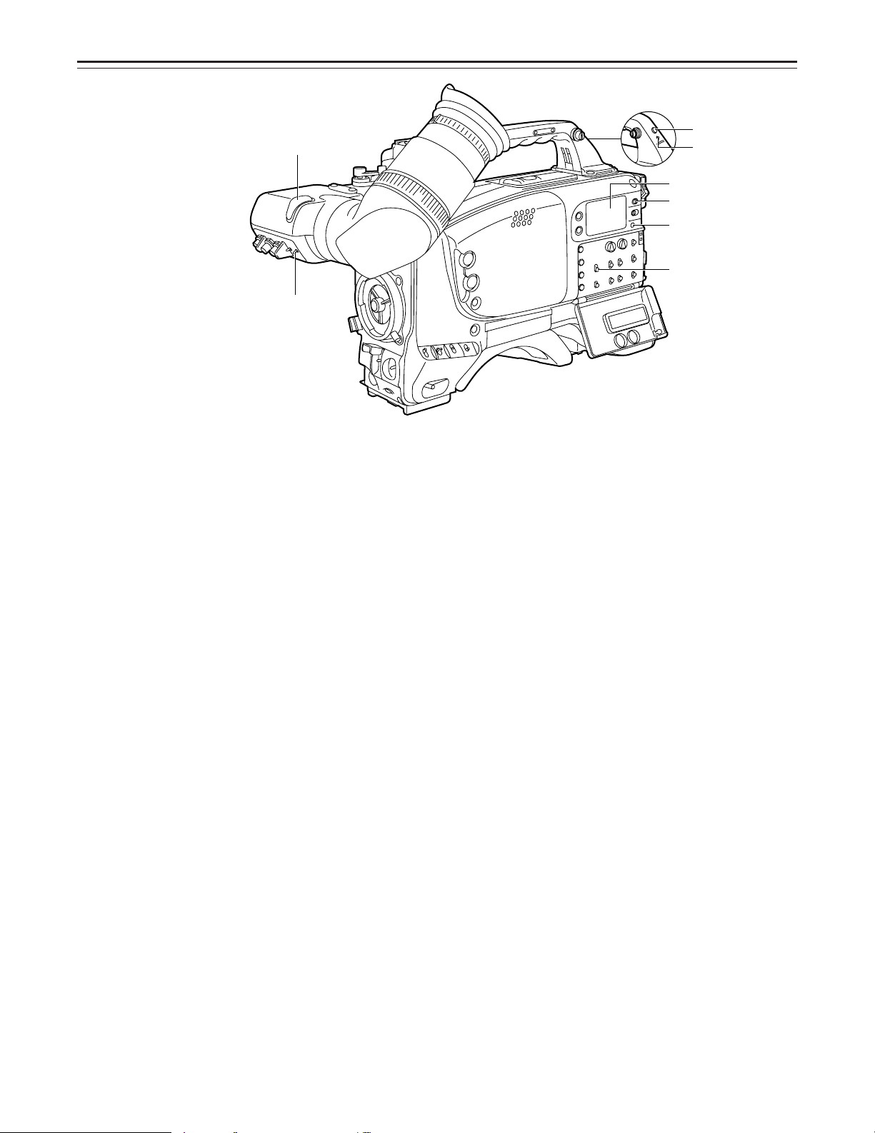
Time Code-Related Section (2)
Ä HOLD button
The time data appearing on the counter display at the instant when this button is pressed is
held. (The time code generator will still continue to run.) When the button is pressed again,
the hold status is released. Use the button to ascertain the time at which a particular scene
was shot, for example.
Å RESET button
This resets the time data on the counter display to “00:00:00:00”. When the TCG switch É is
set to SET and this button is pressed, the time code or user’s bit can be reset to
“00:00:00:00” or “00 00 00 00”.
Æ DISPLAY switch
The time code, CTL or user’s bit is made to appear on the counter display depending on the
setting positions of this switch and the TCG switch É.
UB: The user’s bit is displayed.
TC: The time code is displayed.
CTL: CTL is displayed.
Ç UP button, DOWN button
When setting the time code or user’s bit, these buttons increment or decrement by 1 the figure of the digit made to flash by the SHIFT/ITEM button È.
È SHIFT/ITEM (digit advance) button
When setting the time code or user’s bit, this button is used to cause the digit which is to be
set to flash.
√
–21–
Controls and Their Functions
À
É TCG (time code selector) switch
This is used to set the running mode of the internal time code generator.
F-RUN: This position is used when the time code is to be advanced continuously regardless
of the VTR’s operation.
Set to this position when aligning the time code with the actual time or locking the
time code to an external source.
SET: This position is used for setting the time code or user’s bit.
R-RUN: This position is used when the time code is to be advanced only while recording is
in progress. The time code will be recorded continuously on a tape with a succes-
sion of unedited shots.
Ã
Õ
–
œ
Œ
…
Warning/Status Display Section
Ê Tally lamp
This is activated when the TALLY switch Ë is at HIGH or LOW, and it lights during recording
by the VTR section. It flashes in the same way as the REC lamp inside the viewfinder to warn
the operator. The brightness when lighted can be selected using the TALLY switch (HIGH or
LOW).
Ë TALLY switch
This controls the tally lamp Ê.
HIGH: The tally lamp is made brighter.
OFF: The tally lamp is extinguished.
LOW: The tally lamp is made darker.
Ì Back tally lamp
This functions in the same way as the tally lamp Ê when the back tally switch Í is set to
ON.
Í Back tally switch
This controls the back tally lamp Ì.
ON: The back tally lamp operates.
OFF: The back tally lamp does not operate.
Î WARNING lamp
This flashes or lights when trouble occurs in the VTR section.
Ï LIGHT switch
ON: This illuminates the display window Ð.
OFF: This extinguishes the display window illumination.
Ð Display window
The warnings related to the VTR section, remaining battery level, sound level, time data, etc.
are displayed in this window.
–22–
Power Supply
Power can be supplied to the unit using a battery pack or AC power supply.
Using a battery pack
A Panasonic, B Anton Bauer or C Sony batteries can be used for the battery pack.
Before using a battery pack, be sure to charge it completely using a battery charger.
ÁSee the Handling Instructions for the battery pack and battery charger for a detailed explana-
tion of charging methods.
Using an Anton Bauer Battery Pack
1 Mount the battery pack.
Insert the battery pack in the direction of the arrow and then slide it into place.
Power Supply Output Connector
Control Switch
2 When detaching the battery, hold down the detachment lever of the battery holder and slide
the battery pack in the direction of the arrow.
Lever
Pack
|Note{
The AJ-D400 supports the intelligent battery system and the ultra-light system.
Automatic detection can be performed for intelligent batteries with a remaining battery level
of 10% or more. At this time, the remaining battery level is displayed numerically (percentage display) inside the viewfinder. If the power is turned on with a remaining battery level of
10% or less, the voltage is displayed. Also, after intelligent battery detection, the remaining
battery level display indicates the level for the intelligent battery even if power is supplied
from an external source.
–23–
Power Supply
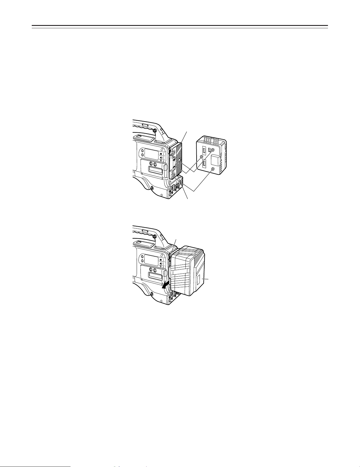
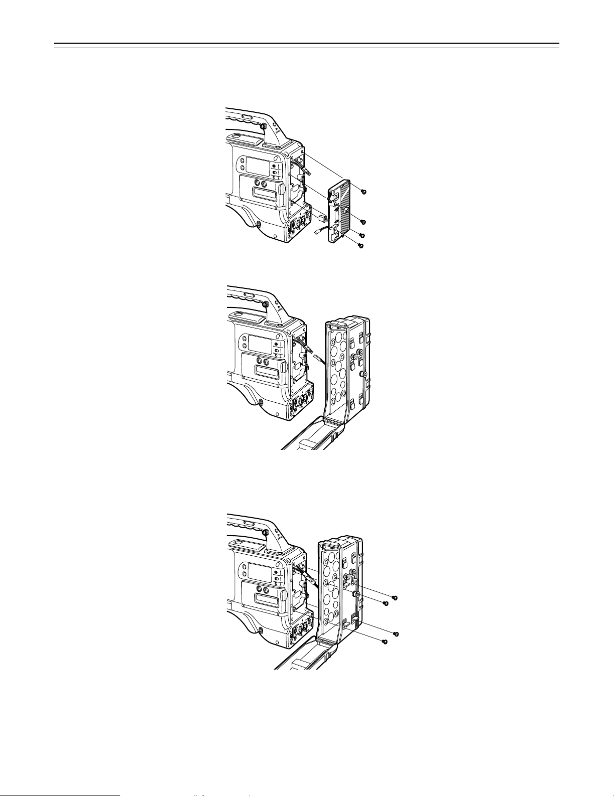
Using the Panasonic AU-BP402 Battery Pack
1 Detach the battery mounts.
2 Connect the unit’s connectors with the connectors of the AU-M402H battery case.
3 Mount the AU-M402H battery case.
Open the battery case cover and lift up the rubber cap to expose the screw holes. Tighten
the screws with a screwdriver and mount the case to the unit. Be sure to tighten the screws
completely.
|Notes{
ÁDo not pull strongly on the rubber cap.
ÁTake care not to catch the connection cord between the battery case and the main unit.
–24–
Power Supply
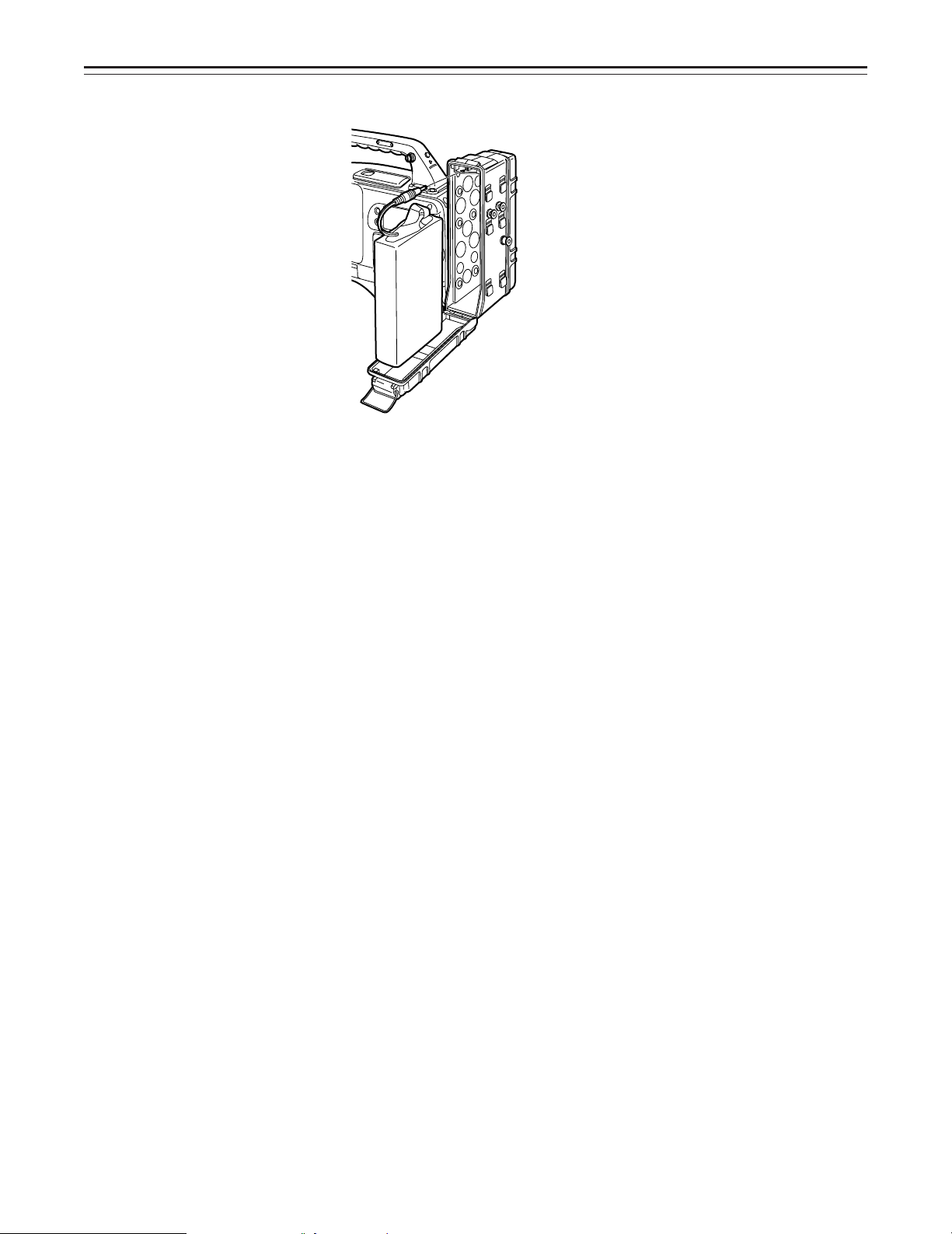
4
Connect the battery pack plug to the connector inside the case and insert the battery pack.
|Note{
The unit’s power must be set to OFF before the plug is inserted or removed.
–25–
Power Supply
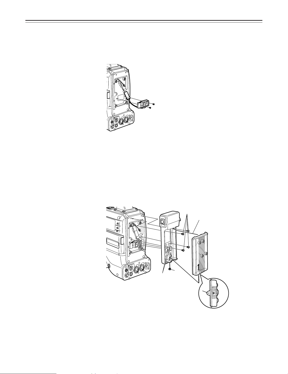
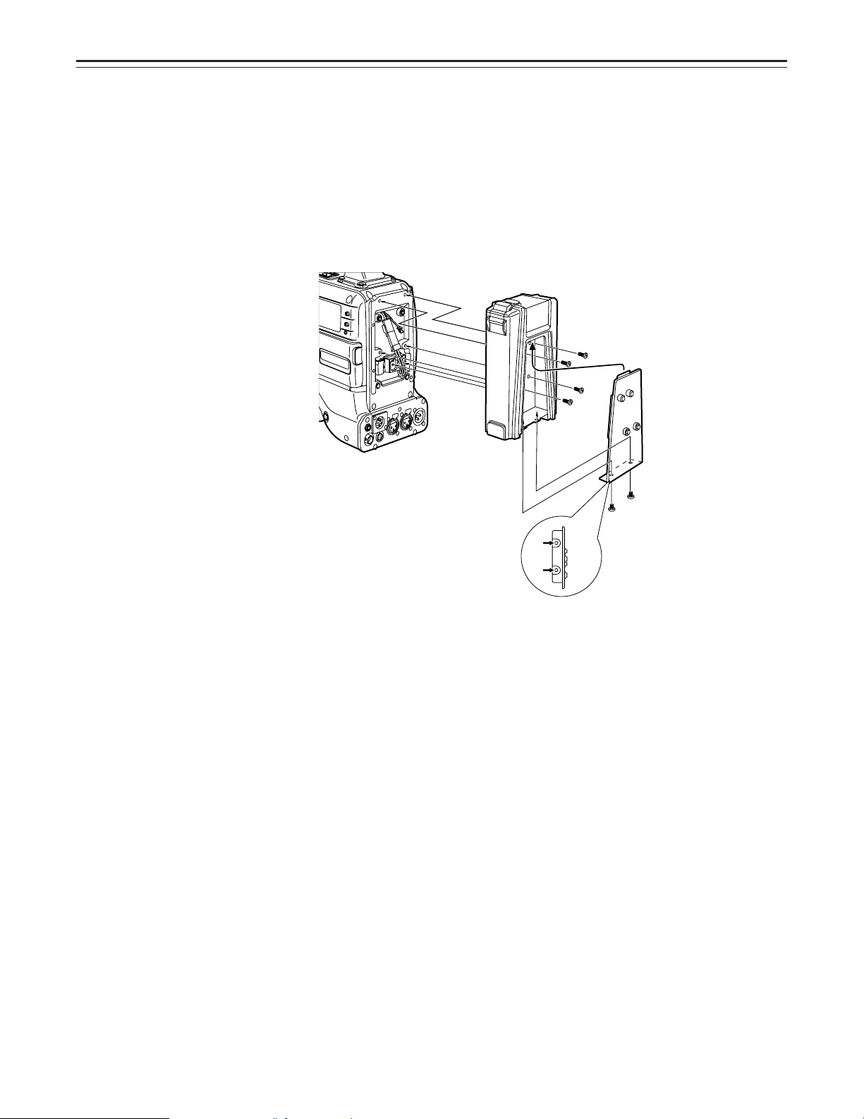
Using a Sony Battery Pack
1 Remove the battery mounts.
See page 24.
2 Mount the accessory battery mounting connector.
3 Mount the Sony battery holder.
Mount the battery case with the cover detached first, and then mount the detached cover as
shown in the figure.
A Tighten the mounting screws.
B Tighten the power supply contact screws.
C Insert the top of the detached cover in the direction of the arrow.
D Align the hole at the bottom (metal part) of the cover with the hole at the bottom of the
case and mount the cover to the battery mounting connector with the screw of the battery holder.
A
C
B
D
|Note{
Take care when attaching the battery holder that the wires are not pinched.
–26–
Power Supply
Using the Sony BP-90 Battery Pack
1 Mount the accessory battery mounting connector.
(See the preceding page.)
2 Mount the BP-90 battery case.
A Tighten the mounting screws.
B Tichten the power supply contact screws.
C Insert the top of the detached cover in the direction of the arrow.
D Align the hole at the bottom (metal part) of the cover with the bottom of the case and
mount the cover to the battery mounting connector with the screw.
|Notes{
ÁThe unit’s power must be set to OFF before the plug is inserted or removed.
ÁTake care when attaching the battery case that the wires are not pinched.
–27–

Power Supply
Using an AC Power Supply (When using the AJ-B75 AC Adaptor)
1 Connect the unit’s EXT DC IN socket with the DC OUT connector of the AJ-B75 AC
adaptor.
DC IN Connector
2 Set the AC adaptor’s power to ON.
3 Set the unit’s power switch to ON.
|Notes{
ÁWhen using an external power supply other than the AJ-B75 AC adaptor, check the pin signal
of the EXT DC IN socket.
ÁWhen both a battery pack and AC adaptor are connected, power is supplied from the AC
adaptor.
ÁWhen using an AC adaptor, the AC adaptor’s power must be set to ON before the unit’s POW-
ER switch is set to ON. If this sequence is reversed, the AC adaptor’s output voltage will rise
slowly and may cause the unit to malfunction.
Pin No. Signal
1 GND
2, 3 ——
4 o12 V
4
3
2
1
–28–
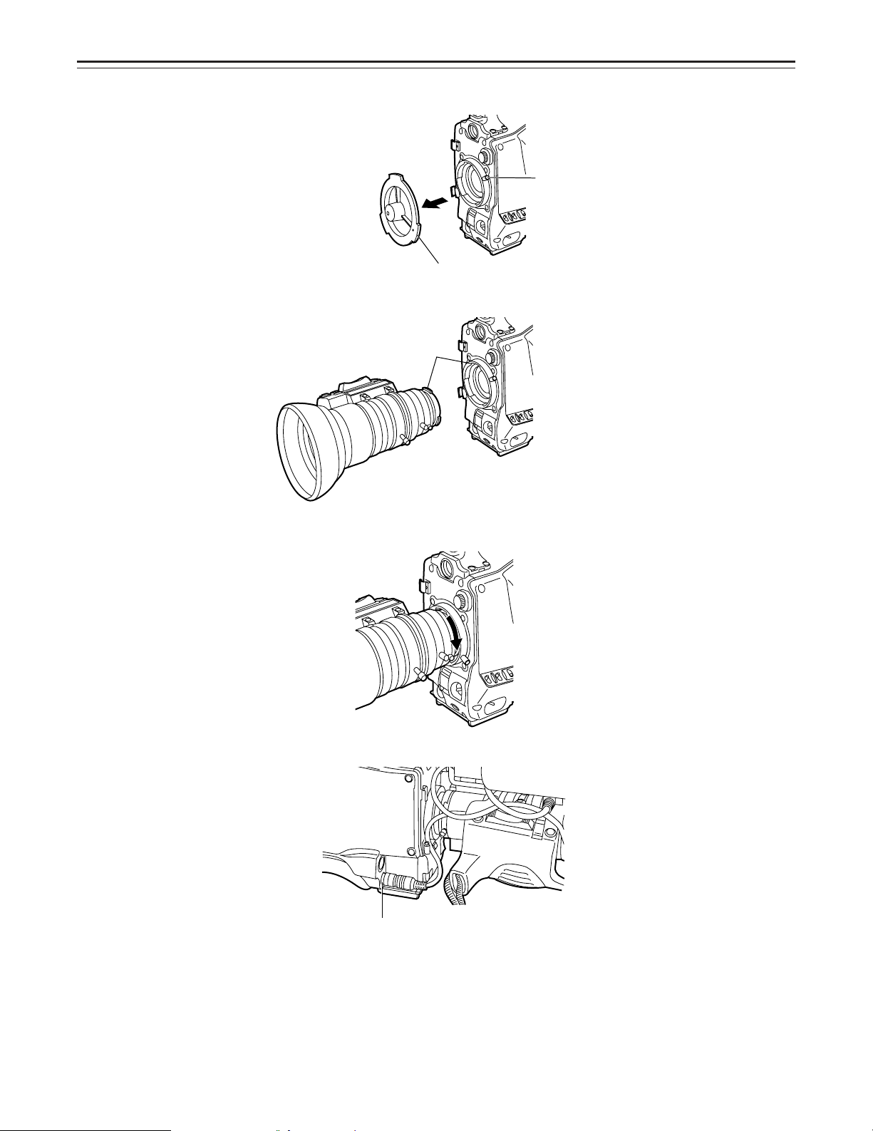
Mounting the Lens
1
2 Align the indentation at the top center of the lens mount with the center mark of the lens and
Raise the lens clamping lever and remove the mount cap.
Lens Clamping Lever
Mount Cap
mount the lens.
Mark
3 Lower the lens clamping lever and clamp the lens.
4 Press the cable into the cable clamp and connect it to the LENS connector.
LENS Connector
ÁSee the Handling Instructions provided with the lens for lens handling.
|Note{
The lens and camera adjustments listed below may be necessary depending on the lens to be
mounted.
1. Lens flanging adjustment
2. Lens auto iris adjustment
3. Lens white shading adjustment (with this unit)
–29–
Adjusting the Lens Flange
When images are not clearly focused at both the telephoto and wide-angle positions during
zoom operations, adjust the flange back (the distance from the lens mounting surface to the image formation surface).
Once adjusted, the flange back does not need to be readjusted as long as the lens is not
changed.
Adjustment method
Check the position of each part of the lens which must be operated in order to adjust the flange
back with the lens Handling Instructions.
Approx. 10 ft
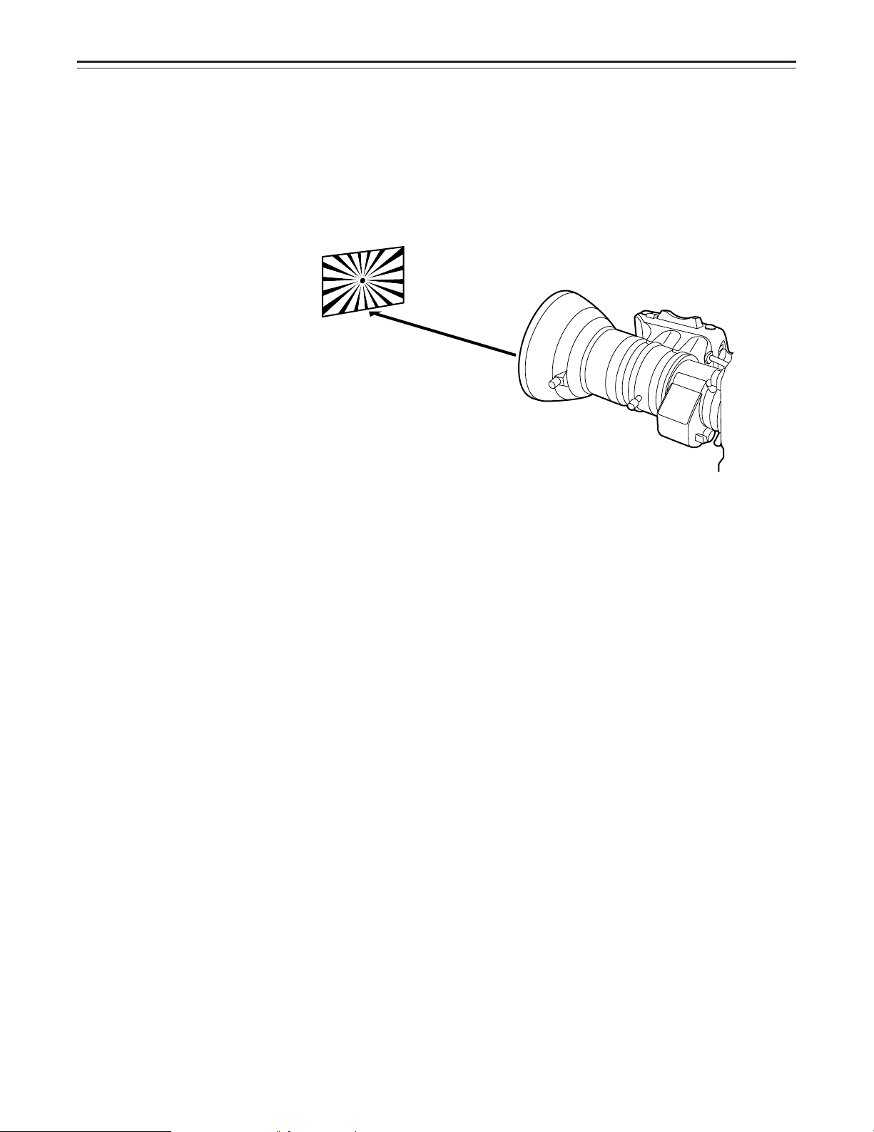
Adjusting the Flange Back
1 Set the lens iris to manual.
2 Open the iris. Position the flange back adjustment chart about 10 ft from the lens and illumi-
nate it so that an appropriate image output level is obtained.
If the image level is too high, use the CC/ND filters or the shutter.
3 Loosen the Ff ring clamping screw.
4 Set the zoom ring to the telephoto position manually or by electric drive.
5 Shoot the flange back adjustment chart and turn the distance ring to bring the chart into
focus.
6 Set the zoom ring to the wide-angle position.
7 Turn the Ff ring to bring the chart into focus.
At this time, take care not to move the distance ring.
8 Repeat this operation four to seven times until the lens is in focus at both the telephoto and
wide-angle positions.
9 Firmly tighten the Ff ring clamping screw.
ÁRefer to the Operating Instructions of the lens.
–30–
 Loading...