

Panasonic AJ-D230HP User Manual
Digital Video Cassette Recorder
AJ-
P
Operating Instructions
Printed in Japan
VQT7626
S0698W
IMPORTANT
“Unauthorized recording of copyrighted
television programs, video tapes and other
materials may infringe the right of copyright
owners and be contrary to copyright laws.”
CAUTION: TO REDUCE THE RISK OF ELECTRIC SHOCK,
REFER TO SERVICING TO QUALIFIED SERVICE PERSONNEL.
DO NOT REMOVE COVER (OR BACK).
NO USER SERVICEABLE PARTS INSIDE.
The lightning flash with arrowhead symbol,
within an equilateral triangle, is intended to
alert the user to the presence of uninsulated
“dangerous voltage”
enclosure that may be of sufficient magnitude
to constitute a risk of electric shock to
persons.
The exclamation point within an equilateral
triangle is intended to alert the user to the
presence of important operating and
maintenance (service) instructions in the
literature accompanying the appliance.
within the product’s
CAUTION:
Do not install or place this unit in a bookcase,
built in cabinet or in another confined space
in order to keep well ventilated condition.
Ensure that curtains and any other materials
do not obstruct the ventilation condition to
prevent risk of electric shock or fire hazard
due to overheating.
WARNING:
TO REDUCE THE RISK OF FIRE OR SHOCK
HAZARD, DO
NOT
EXPOSE
EQUIPMENT TO RAIN OR MOISTURE.
CAUTION:
TO REDUCE THE RISK OF FIRE OR SHOCK
HAZARD AND ANNOYING INTERFERENCE,
USE THE RECOMMENDED ACCESSORIES
ONLY.
FCC Note:
This device complies with Part 15 of the FCC Rules.
To assure continued compliance follow the attached
installation instructions and do not make any
unauthorized modifications.
This equipment has been tested and found to comply
with the limits for a class A digital device, pursuant to
Part 15 of the FCC Rules. These limits are designed
to provide reasonable protection against harmful
interference when the equipment is operated in a
commercial environment. This equipment generates,
uses, and can radiate radio frequency energy and, if
not installed and used in accordance with the
instruction manual, may cause harmful interference to
radio communications. Operation of this equipment in
a residential area is likely to cause harmful
interference in which case the user will be required to
correct the interference at his own expense.
THIS
Do not insert fingers or any objects into the video
cassette holder.
Avoid operating or leaving the unit near strong
magnetic fields. Be especially careful of large audio
speakers.
Avoid operating or storing the unit in an excessively
hot, cold, or damp environment as this may result in
damage both to the recorder and to the tape.
Do not spray any cleaner or wax directly on the unit.
If the unit is not going to be used for a length of time,
protect it from dirt and dust.
Do not leave a cassette in the recorder when not in
use.
Do not block the ventilation slots of the unit.
Use this unit horizontally and do not place anything on
the top panel.
Cassette tape can be used only for one-side, one
direction recording. Two-way or two-track recordings
cannot be made.
Cassette tape can be used for either Color or Black &
White recording.
Do not attempt to disassemble the recorder.
There are no user serviceable parts inside.
If any liquid spills inside the recorder, have the
recorder examined for possible damage.
Refer any needed servicing to authorized service
personnel.
2
Table of Contents
Introduction
Features
Controls and Their Functions
Front panel
Connector section
Tapes
Operation
Switching on the power and inserting the cassette
Stop mode
Recording
Pause/still recording (back-space assemble recording)
Playback
Cue and Review
Still-picture playback
Frame advance
Sound selection
Repeat playback
5
5
6
6
9
11
12
12
13
14
15
15
16
16
16
16
17
Time Code and User’s Bit
Time code
User’s bit
Setting the time code
Setting the user’s bit
Time code and user’s bit playback
Superimposed Display Screens
Set-up (Default Settings)
Set-up Menus
BASIC menu
OPERATION menu
INTERFACE menu
MEMORY MODE menu
TAPE PROTECT menu
TIME CODE menu
VIDEO menu
AUDIO menu
19
19
19
20
20
21
22
23
24
24
25
26
27
27
28
29
30
3

Table of Contents
RS-232C Interface
1. Hardware specifications
1) Interface specifications
2) Communication parameters
2. Software specifications
1) External interface specifications
2) Sending format (from personal computer to VTR)
3) Receiving format (from VTR to personal computer)
4) Command list
Error Messages
Video Head Cleaning
Condensation
Maintenance
Specifications
30
31
31
31
32
32
32
32
34
36
37
37
37
38
4

Introduction
The model AJ-D230H is a digital VTR which uses 1/4-inch wide tapes.
It features digital compression technology which significantly reduces the deterioration in the picture and sound
quality during dubbing compared with conventional analog systems.
With its compact and lightweight design, the unit can be carried around with the greatest of ease, and it is also
easy to install it in a rack.
An interactive format is used to perform the unit’s settings while monitoring the menus on the screen of the TV
monitor.
The model AJ-D230H is provided with an RS-232C connector as a standard feature to enable the unit to be
operated by remote control from a computer.
Features
Compact size and light weight
The unit measures 8-7/16” wide, 5-1/4” high and 157/16”deep, and it weighs only 15.4 Ibs.
Grips are incorporated to make the unit easy to
carry.
2-channel digital audio with high sound quality
Computer control
The unit can be operated by remote control from a
computer by connecting the RS-232C cable
between the unit and the computer.
Up to 126 minutes of recording
Either news-gathering cassette tapes (max. 66
minutes) or general-purpose cassette tapes (max.
126 minutes) can be used. In both cases, the tape
is one-fourth of an inch wide to achieve a compact
design.
Compatibility with consumer-use equipment
Consumer-use cassette tapes which have been shot
using a consumer-use digital camera can be played
back on this unit using the cassette adaptor (AJCS750P: option).
Please note that the LP mode is not supported.
Time code
This unit incorporates a time code generator
(TCG)/time code reader (TCR).
Repeat playback
Repeat playback can be performed continuously or
only once for any section of the tape.
Menu-driven set-up
An interactive system is used to perform the unit’s
settings while monitoring the menus appearing on
the screen of the TV monitor.
Remote control
Connection of the AG-A11 remote controller (option)
enables the unit to be operated at a distance of
about 5 meters.
Digital interface
By installing the digital interface board (option) and
connecting the unit using the DVCPRO terminal
(complying with the IEEE1394 standard), it is
possible to dub tapes with hardly any resulting
deterioration in the picture and sound quality at all.
5
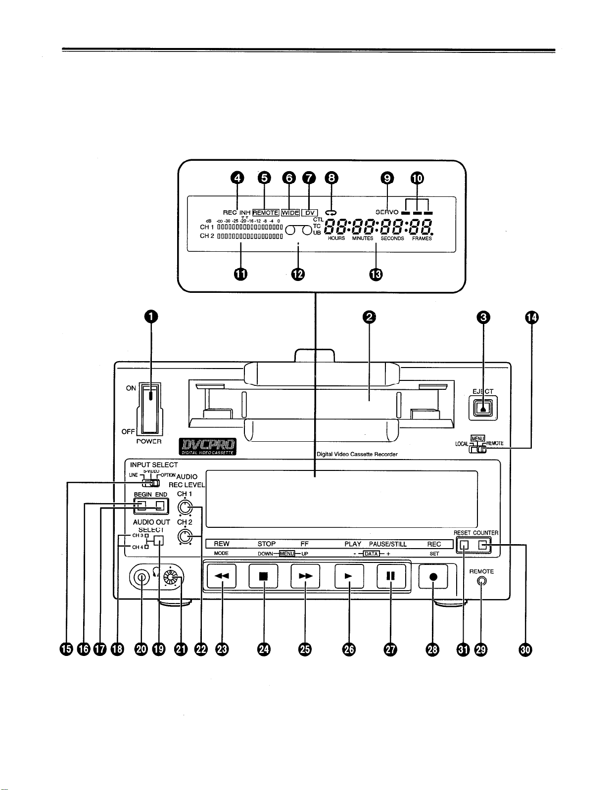
Controls and Their Functions
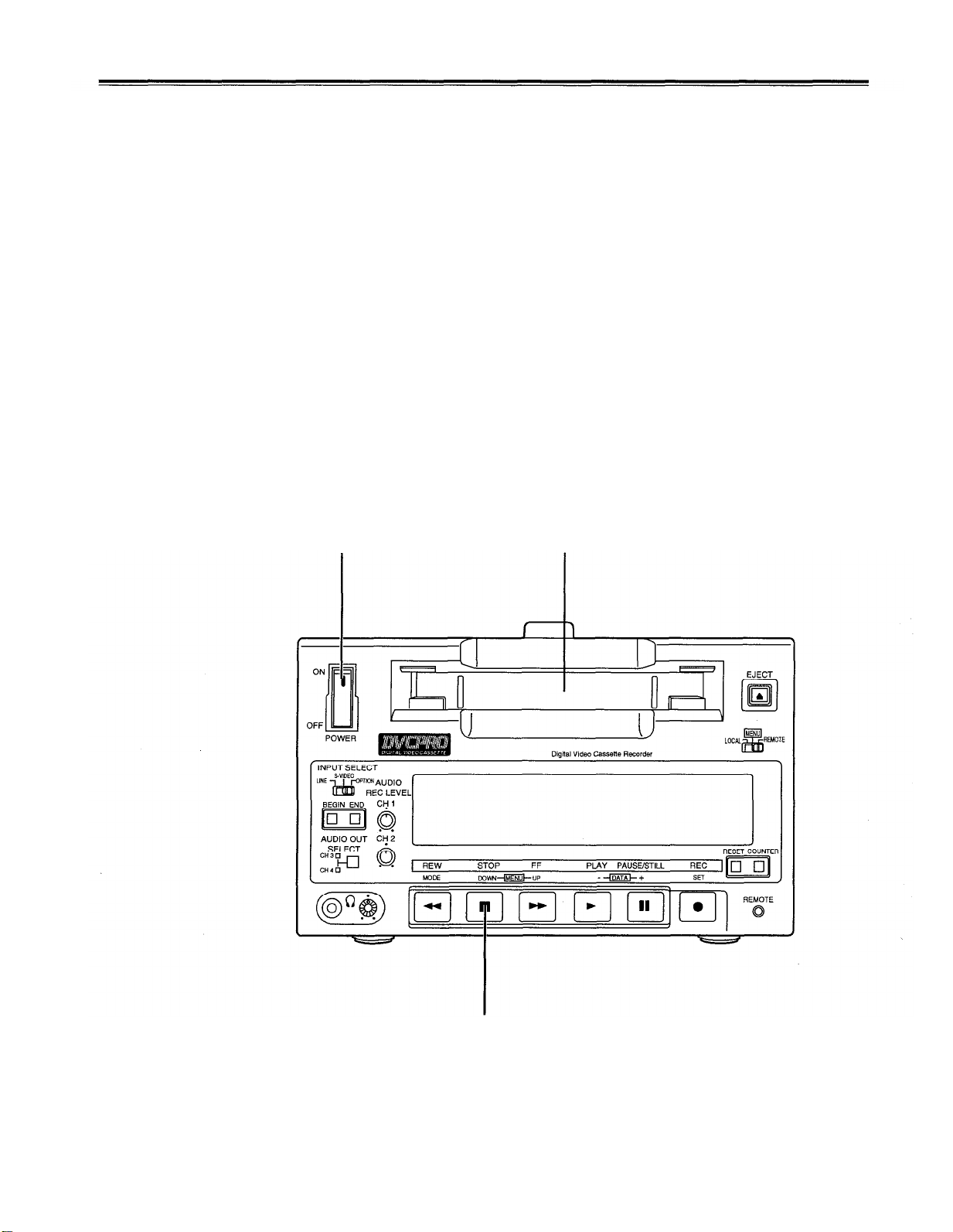
Front Panel
Counter display area
6
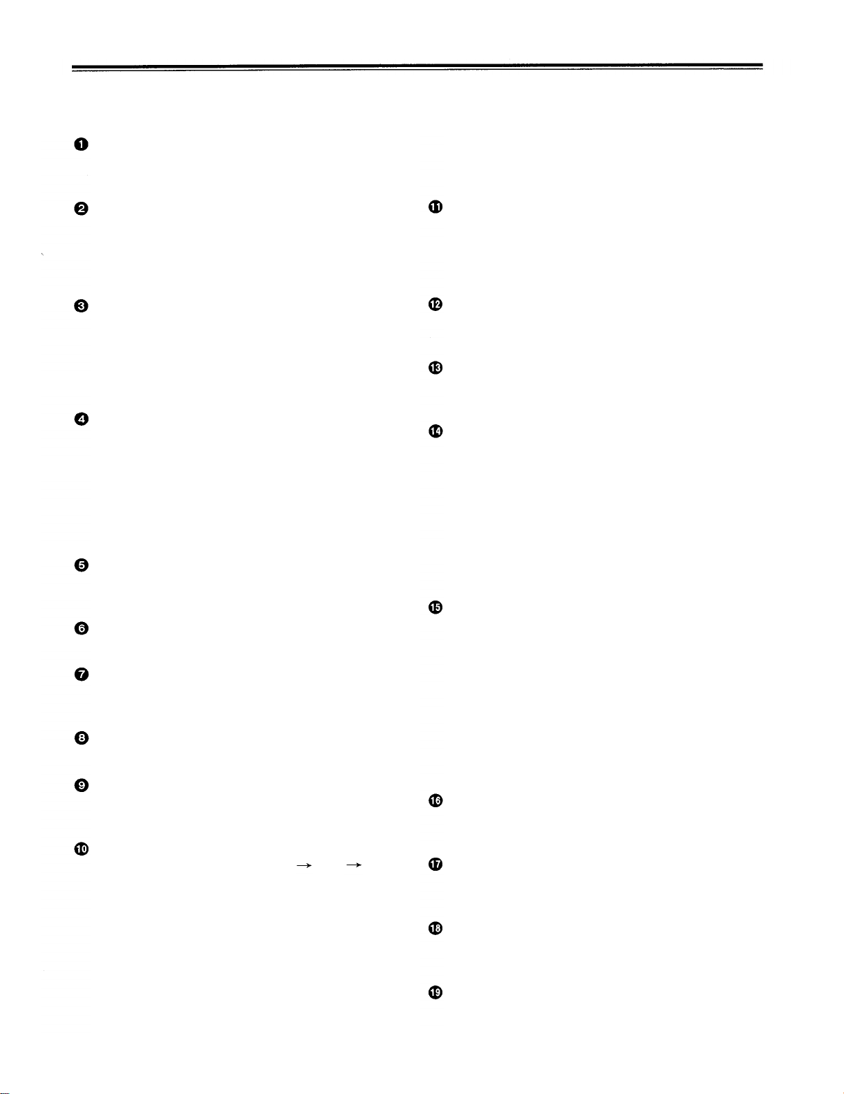
Controls and Their Functions
Front panel
POWER switch
When the ON side is pressed, the power is turned
on, and the counter display area lights.
Red:
This lights when either the video or audio
playback
interpolated.
signals
are
corrected or
Cassette slot
A news gathering cassette, general-purpose
cassette or consumer-use cassette with an adaptor
is loaded through this slot. Consumer-use
cassettes can be played back only.
EJECT button
When this is pressed, the tape is unloaded, and
several seconds later the cassette is automatically
ejected.
When the counter display area shows the CTL
display, the display is now reset.
REC/REC INH lamp
REC:
REC INH:
REMOTE lamp
This lights when the LOCAL/MENU/REMOTE
switch has been set to the REMOTE position.
WIDE lamp
This lights in the 16:9 wide screen mode.
“Consumer-use cassette loaded” display lamp
This lights when a cassette recorded on a
consumer-use DV unit has been loaded.
REPEAT lamp
This lights during repeat playback.
SERVO lamp
This lights when the drum servo and capstan servo
are locked.
Channel condition lamps
One of these lamps lights (green
accordance with the status of the error rates.
Green:
Blue:
This lights during recording.
This lights when the cassette has been
set to the accidental erasure prevention
status.
It also lights when REC INHIBIT has
been set to ON on the setup menu.
In this status, recording is not possible.
blue red) in
This lights when the error rates for the video
and audio playback signals are both
satisfactory.
This lights when the error rate for either the
video or audio playback signals has
deteriorated. The playback picture is still
normal even while this lamp is lighted.
Level meter
This displays the audio signal levels.
The input audio signal levels are displayed during
recording and E-E selection; the output audio signal
levels are displayed during playback.
“Cassette loaded” display lamp
This lights when a cassette has been loaded into
the unit.
Counter display area
The TC and CTL counts, on-screen information and
messages appear in this area.
LOCAL/MENU/REMOTE switch
This is operated when menu settings are to be
performed or when the unit is to be controlled from
a remote location.
LOCAL:
MENU:
REMOTE:
INPUT SELECT switch
This is used to select the input signals.
LINE:
S-VIDEO:
OPTION:
BEGIN button
This sets the repeat playback start point, and it
displays the currently entered start point.
END button
This sets the repeat playback end point, and it
displays the currently entered end point.
CH3/CH4 lamp
This lights during DV format playback when the
audio signals have been set in CH3 and CH4.
AUDIO OUT SELECT button
This selects the audio signals which are to be
output.
For controlling the unit using the controls
on the unit’s operation panel.
For setting the on-screen menu.
For controlling the unit with an RS-232C
or other external control unit.
For recording signals which have been
supplied to the video signal input
connector.
For recording signals which have been
supplied to the S-VIDEO input connector.
For supplying video and audio signals
from an optional board and recording
them.
7
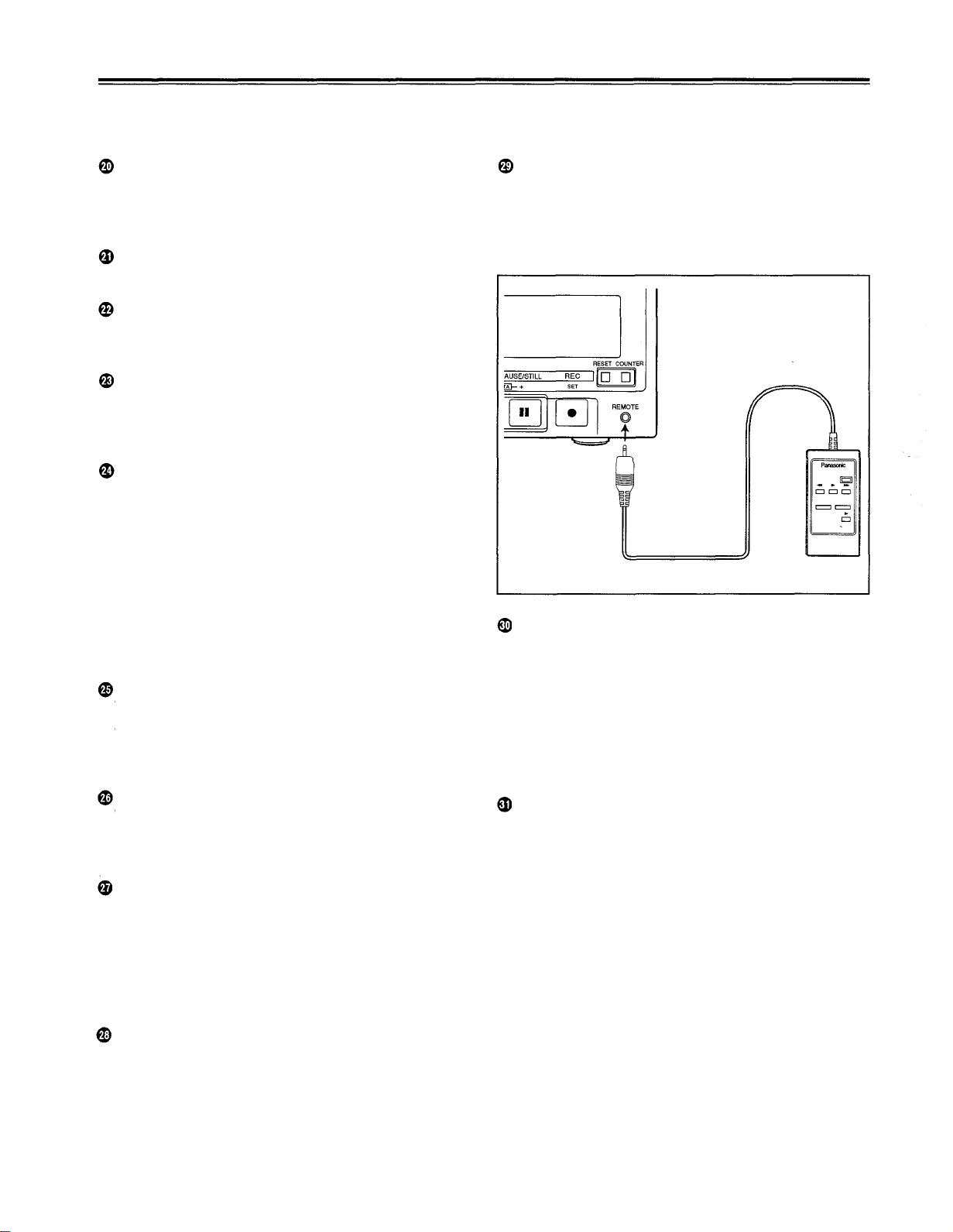
Controls and Their Functions
Headphone jack
When stereo headphones are connected here, the
recording or playback sound can be monitored
through the headphones.
Volume control
This is for adjusting the headphones volume.
Volume recording level control
This is for adjusting the PCM audio signal CH1/CH2
recording level.
REW button
When this is pressed, the tape is rewound, and
when "TAPE" is set for the "S/F/R EE SEL" set-up
menu item, the playback picture can be monitored.
STOP button
When this is pressed, the tape stops traveling, and
when "TAPE" is set for the "S/F/R EE SEL" set-up
menu item, the still picture can be monitored. Even
in the stop mode, the drum continues to rotate with
the tape kept in close contact with the drum. After
the unit has been kept in the stop mode for a
specific period of time, it is automatically set to the
standby off mode in order to protect the tape. It is
set to the stop mode immediately after a cassette
has been loaded into the unit.
FF button
When this is pressed, the tape is fast forwarded,
and when "TAPE" is set for the "S/F/R EE SEL" set-
up menu item, the playback picture can be
monitored.
PLAY button
When this is pressed, playback commences. When
it is pressed together with the REC button,
recording commences.
“
Remote control connector
When the remote controller (AG-A11) is connected
to this connector, the unit can be operated from a
distance by this controller instead of by its function
buttons. In this case, the LOCAL/MENU/REMOTE
switch must be set to the REMOTE position.
(AG-A11)
COUNTER button
This switches the display on the counter display
area.
CTL:
The tape timer (control signal) is displayed.
TC:
The time code is displayed.
UB:
The user's bit is displayed.
Remaining tape:
The amount of tape remaining is displayed.
RESET button
When this is pressed in the CTL mode, the counter
display is reset to 00:00:00:00.
PAUSE/STILL button
When this is pressed during recording, the tape
travel is temporarily stopped (pause mode). When
it is pressed again, recording is resumed.
When this is pressed during playback, the still
picture mode is established. When it is pressed
again, playback is resumed.
REC button
When this is pressed together with the PLAY
button, recording commences.
8
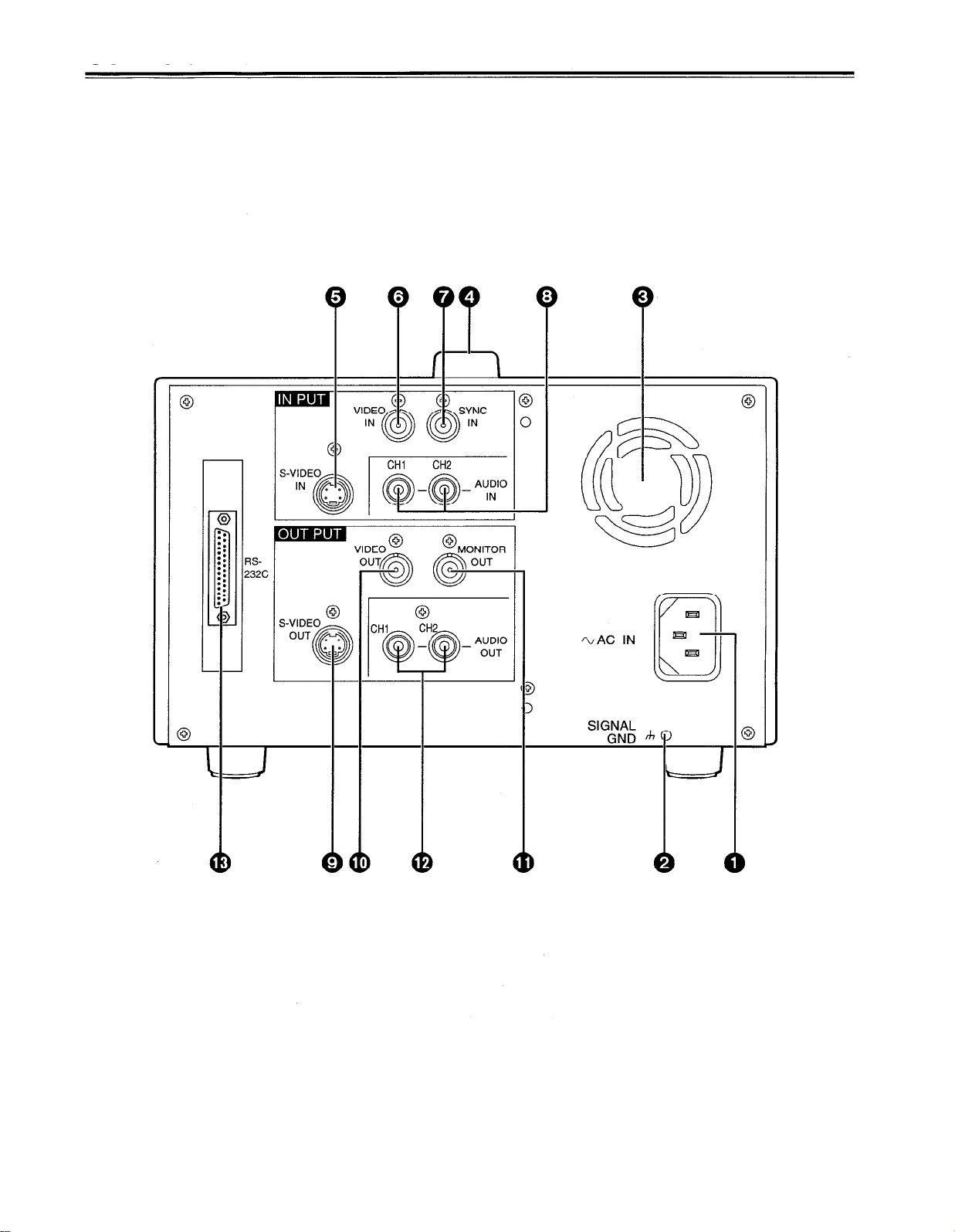
Controls and Their Functions
Connector section
9
Controls and Their Functions
Connector section
AC IN connector
Use the power cord supplied to connect this connector to the power outlet.
SIGNAL GND terminal
This is connected to the signal ground terminal on the unit connected in order to reduce the
noise. It is not a safety ground.
Fan motor
This is for cooling the unit.
Handle
S-VIDEO IN connector
This is the input connector for the S-VIDEO video signals.
VIDEO IN connector
This is the input connector for the analog video signals.
SYNC IN connector
This is connected to the composite sync signals of a reference sync signal generator if
synchronization with an external reference sync signal is to be obtained during playback.
AUDIO IN connector
This is the input connector for the analog audio signals.
S-VIDEO OUT connector
This is the output connector for the S-VIDEO video signals.
VIDEO OUT connector
This is the output connector for the analog video signals.
MONITOR OUT connector
This is the output connector for the video monitor signals.
Superimposed video signals can be output from it.
AUDIO OUT connector
This is the output connector for the analog audio signals.
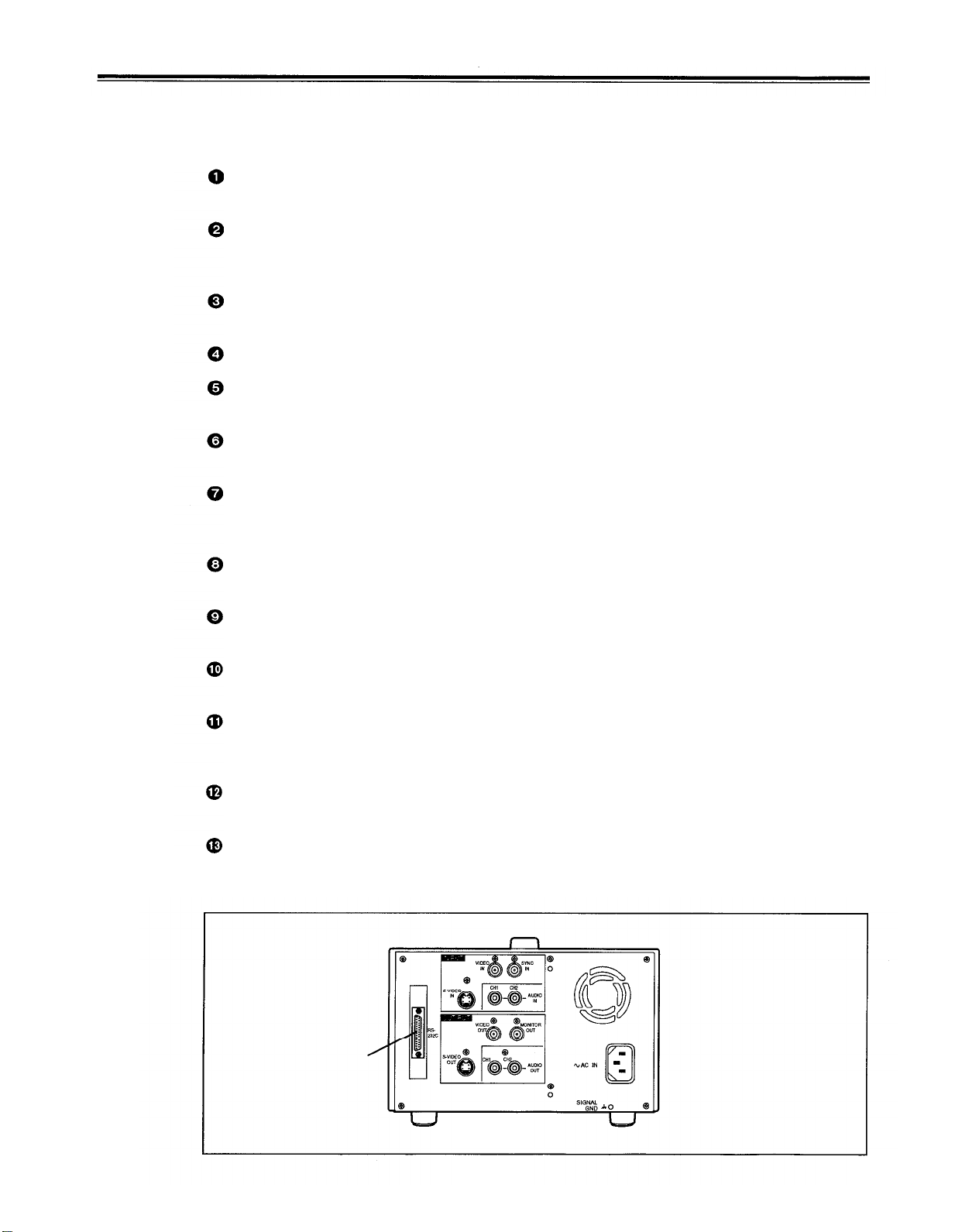
RS-232C connector
Connecting the optional RS-232C cable to this connector enables many kinds of
computerized operations to be performed for the unit.
RS-232C connector
10
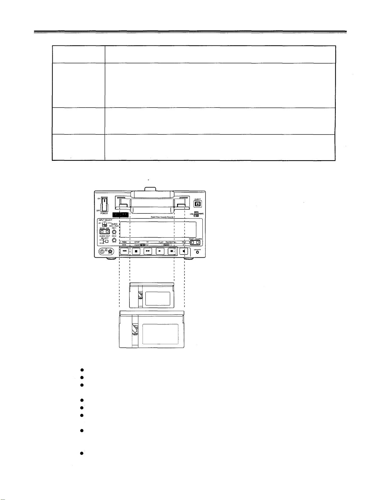
Tapes
Type
Consumer-use
cassette
(S size cassette)
M size cassette
L size cassette
Align the cassette tape with the center of the loading slot, and push it in gently.
then be loaded automatically.
Description
This is exclusively designed for use in consumer-use camera/recorder units. It can be
used in the unit for playback only provided that the cassette adaptor (option) is obtained.
Use of Panasonic consumer DV cassette tape is recommended.
Note that inserting a cassette tape without using the cassette adaptor can damage the
unit.
Recording/playback tape with a maximum length of 66 minutes
(AJ-P12MP, AJ-P24MP, AJ-P33MP, AJ-P46MP, AJ-P66MP)
Recording/playback tape with a maximum length of 126 minutes
(AJ-P34LP, AJ-P66LP, AJ-P94LP, AJ-P126LP)
It will
M size cassette
L size cassette
<Precautions for playing back consumer-use DV tapes>
A consumer-use tape can be used for playback only.
A consumer-use tape recorded in LP mode cannot be played back.
Since a consumer-use tape cannot be used for recording, the unit’s functions related to
recording are prohibited.
The maximum traveling speed of a consumer-use tape is 32× normal tape speed.
The still-picture images on a consumer-use tape may be disturbed.
From the perspective of protecting the tape, refrain from cue-up operation using a consumertape wherever possible.
When a consumer-use tape is employed, the maximum duration of the still timer is set to 10
seconds, and the total time during which the unit is allowed to be left standing in the still mode
is set to 1 minute.
The time code read disabled display may appear when a search is performed on a consumeruse tape or the still-picture image of such a tape is displayed.
11
Operation
Switching on the power and inserting the cassette
Before attempting to operate the unit, make sure that it has been connected properly.
Switch on the power.
1
Insert the cassette tape.
2
Insert the cassette tape into its prescribed position without forcing it in any way.
Check that the STOP lamp has lighted.
3
When the tape is inserted, the cylinder starts rotating automatically, the tape is loaded,
and the unit is set to the stop mode.
1
2
3
12
 Loading...