

Page 1
Operating Instructions/Bedienungsanleitung
Mode d’emploi/Istruzioni per l’uso
Instrucciones de funcionamiento
取扱説明書
1-inch Electronic HD Color View Finder
1-Zoll Elektronischer HD-Farbe-Sucher
HD Couleur Viseur électronique de 1 pouce
HD Colore Mirino Elettronico da 1 pollici
HD Color Visor Electrónico de 1 pulgadas
1 型 HD カラービューファインダー
ModelNo.
Before operating this product, please read the instructions carefully and save this
manual for future use.
Bitte lesen Sie diese Bedienungsanleitung vor der Inbetriebnahme dieses Produkts
aufmerksam durch, und bewahren Sie sie für späteres Nachschlagen auf.
Avant d’utiliser l’appareil, lire attentivement ce mode d’emploi, et le conserver à des
fins de référence ultérieure.
Prima di far funzionare questo prodotto, leggere attentamente le istruzioni e
conservare questo manuale per riferimenti futuri.
Antes de utilizar este producto, lea cuidadosamente las instrucciones y guarde este
manual por si tiene que utilizarlo en el futuro.
このたびは、“ パナソニック製品 ” をお買い上げいただき、まことにありがとうございます。
■ 取扱説明書をよくお読みのうえ、正しく安全にお使いください。
■ ご使用前に「安全上のご注意」(
■ 保証書は「お買い上げ日・販売店名」などの記入を確かめ、取扱説明書とともに大切に保
管してください。
2 〜 4 ページ)を必ずお読みください。
AJ-CVF100G
ENGLISHDEUTSCHITALIANO FRANÇAISESPANÕL
日
本
語
保証書別添付
F0509T0 -F @
Printed in Japan
製造番号は、品質管理上重要なものです。
製品本体と保証書の製造番号をお確かめください。
VQT2C51
Page 2
ENGLISH
Read this first!
For General
_ DO NOT REMOVE PANEL COVERS BY UNSCREWING THEM.
No user serviceable parts inside.
Refer servicing to qualified service personnel.
WARNING:
z TO REDUCE THE RISK OF FIRE OR SHOCK HAZARD, DO NOT EXPOSE THIS
EQUIPMENT TO RAIN OR MOISTURE.
z TO REDUCE THE RISK OF FIRE OR SHOCK HAZARD, KEEP THIS EQUIPMENT AWAY
FROM ALL LIQUIDS. USE AND STORE ONLY IN LOCATIONS WHICH ARE NOT
EXPOSED TO THE RISK OF DRIPPING OR SPLASHING LIQUIDS, AND DO NOT
PLACE ANY LIQUID CONTAINERS ON TOP OF THE EQUIPMENT.
Caution:
z Do not point the eyepiece directly at the sun.
indicates safety information.
E-1
Page 3
Read this first! (Continued)
For USA
This device complies with part 15 of the FCC Rules. Operation is subject to the following two
conditions:
(1) This device may not cause harmful interference, and (2) this device must accept any
interference received, including interference that may cause undesired operation.
FCC Note:
This equipment has been tested and found to comply with the limits for a class B digital device,
pursuant to Part 15 of the FCC Rules. These limits are designed to provide reasonable
protection against harmful interference in a residential installation. This equipment generates,
uses, and can radiate radio frequency energy and, if not installed and used in accordance with
the instruction manual, may cause harmful interference to radio communications. However,
there is no guarantee that interference will not occur in a particular installation. If this
equipment does cause harmful interference to radio or television reception, which can be
determined by turning the equipment off and on, the user is encouraged to try to correct the
interference by one or more of the following measures:
z Reorient or relocate the receiving antenna.
z Increase the separation between the equipment and receiver.
z Connect the equipment into an outlet on a circuit different from that to which the receiver is
connected.
z Consult the dealer or an experienced radio/TV technician for help.
z The user may find the booklet “Something About Interference” available from FCC local
regional offices helpful.
Warning :
To assure continued FCC emission limit compliance, the user must use only shielded interface
cables when connecting to external units. Also, any unauthorized changes or modifications to
this equipment could void the user’s authority to operate it.
ENGLISH
For Canada
NOTIFICATION (Canada)
This class B digital apparatus complies with Canadian ICES-003.
indicates safety information.
E-2
Page 4

Table of Contents
Read this first! ................................................................................................... 1
Features ............................................................................................................. 4
Parts and Their Functions ................................................................................ 4
Adjusting the Viewfinder .................................................................................. 7
Attaching the Viewfinder................................................................................................7
Adjusting the Viewfinder’s left-right position..................................................................8
Adjusting the Viewfinder’s front-back position...............................................................8
Detaching the Viewfinder ..............................................................................................9
Diopter Adjustment......................................................................................................10
Screen Adjustment......................................................................................................10
Cleaning the Eyepiece .................................................................................... 11
Attaching the Microphone.............................................................................. 12
Specifications.................................................................................................. 13
E-3
Page 5
Features
z It is compatible with Multi-format (1080i/720P).
z High resolution color LCD panel will display fine images, making it easy to focus.
z With the 1-inch LCOS panel, it has realized fast response and high resolution equivalent
to a CRT.
z This unit is same size as the conventional B&W HD viewfinder, making it possible to
replace without any modification.
(This unit is compatible with the AJ-HDX900 and AJ-HPX Series. Consult the dealer
regarding other cameras)
z It is possible to easily switch between color and B&W modes using the CHROMA switch.
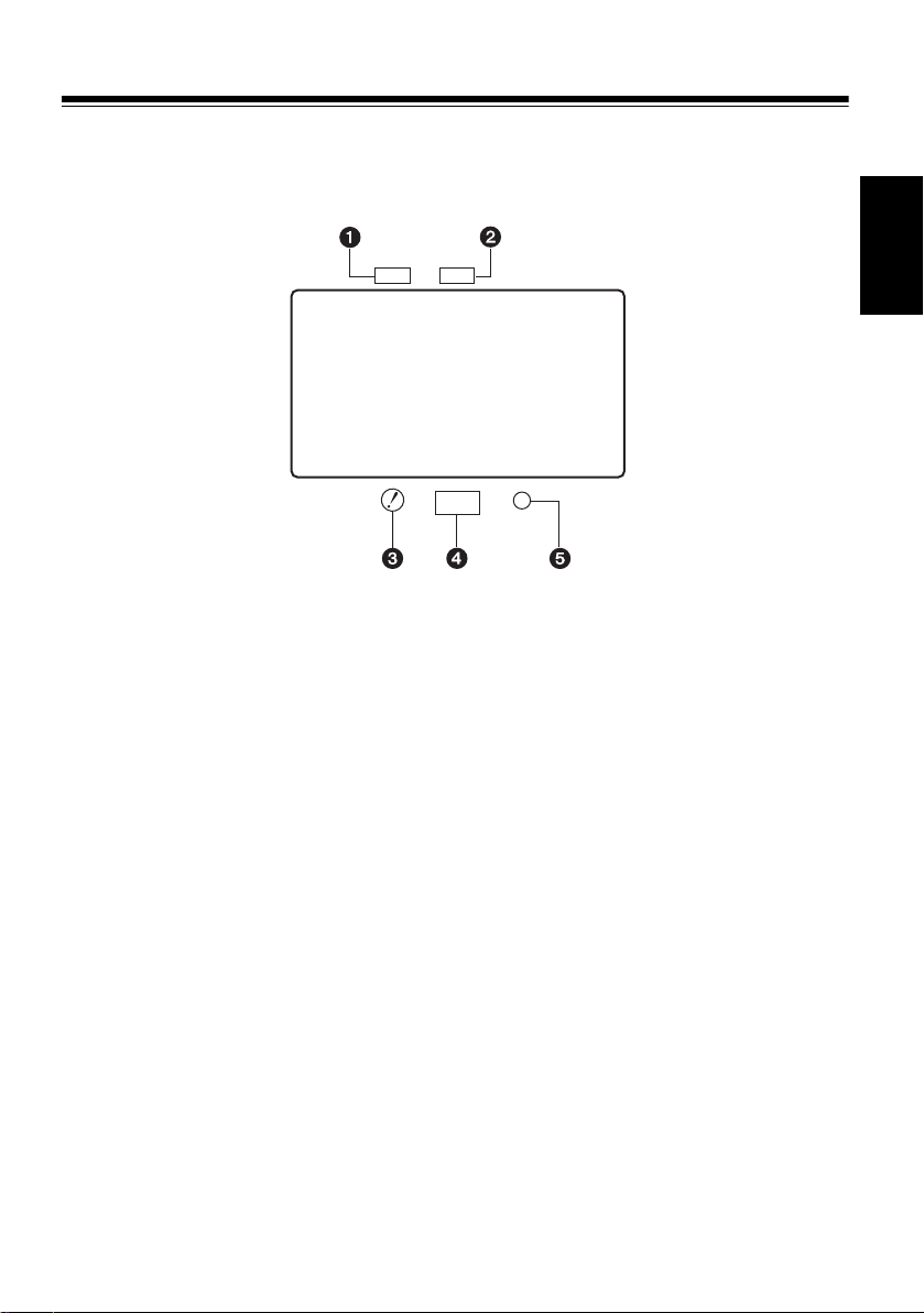
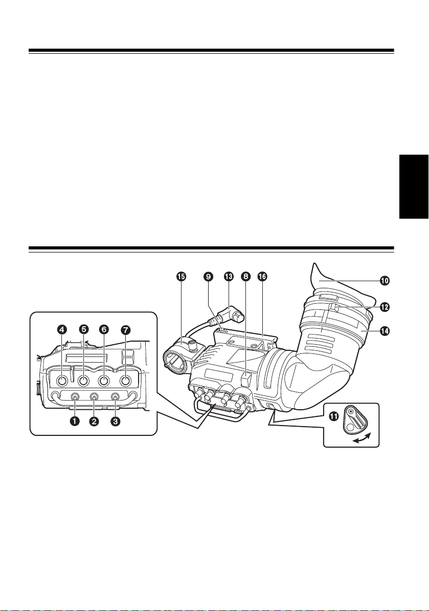
Parts and Their Functions
ENGLISH
CHROMA
PEAKING CONTRAST BRIGHT
OFF
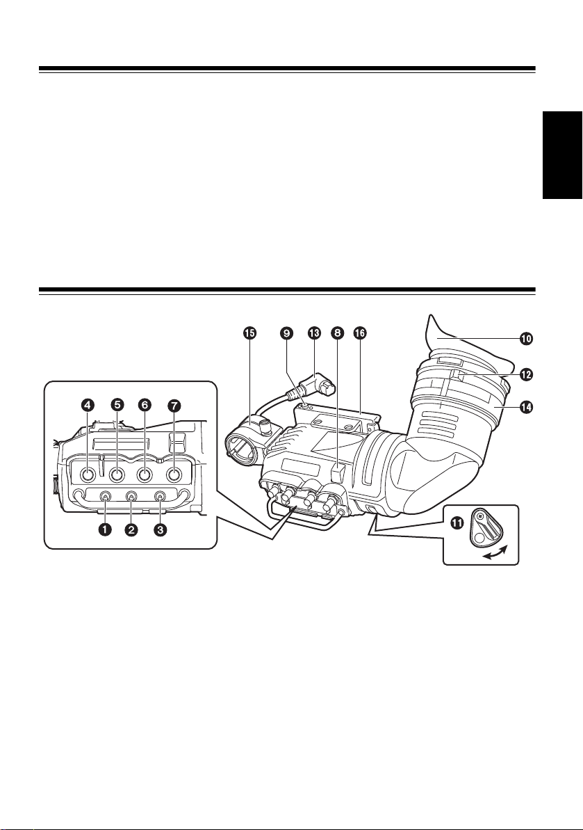
1 CHROMA Switch
Switches the display of the images between color and B&W on the viewfinder.
ON: Displays color images.
OFF: Displays B&W images.
ZEBRA (Zebra Pattern) Switch
2
Displays a zebra pattern inside the viewfinder.
ON: Displays a zebra pattern.
OFF: No zebra pattern is displayed.
The details of the display, such as the type of zebra pattern, will differ depending on the
camera used with the viewfinder. Refer to the instruction manual of the camera for
details.
ON
E-4
Page 6

Parts and Their Functions (Continued)
3 TALLY Sw itch
Controls the front tally lamp.
HIGH: Makes the front tally lamp brighter.
OFF: Turns the tally lamp off.
LOW: Makes the front tally lamp dimmer.
PEAKING Control
4
Adjusts the outlines of the images in the viewfinder to make focusing easier. The
setting of this control has no effect on the output signal of the camera.
CHROMA Control
5
Adjusts the chroma of the color for the image in the viewfinder. The setting of this
control has no effect on the output signal of the camera.
<Note>
In low temperature environments, the colors in the displayed image may be paler
immediately after switching on the power.
6 CONTRAST Control
Adjusts the contrast of the screen inside the viewfinder. The setting of this control has
no effect on the output signal of the camera.
BRIGHT (Brightness) Control
7
Adjusts the brightness of the screen inside the viewfinder. The setting of this control
has no effect on the output signal of the camera.
Front Tally Lamp
8
Lights when the camera is shooting and the TALLY switch is set to HIGH or LOW.
Also, flashes on and off as a warning indication, in the same manner as the REC lamp
inside the viewfinder.
The brightness of the front tally lamp is controlled by the setting of the TALLY switch
(HIGH or LOW).
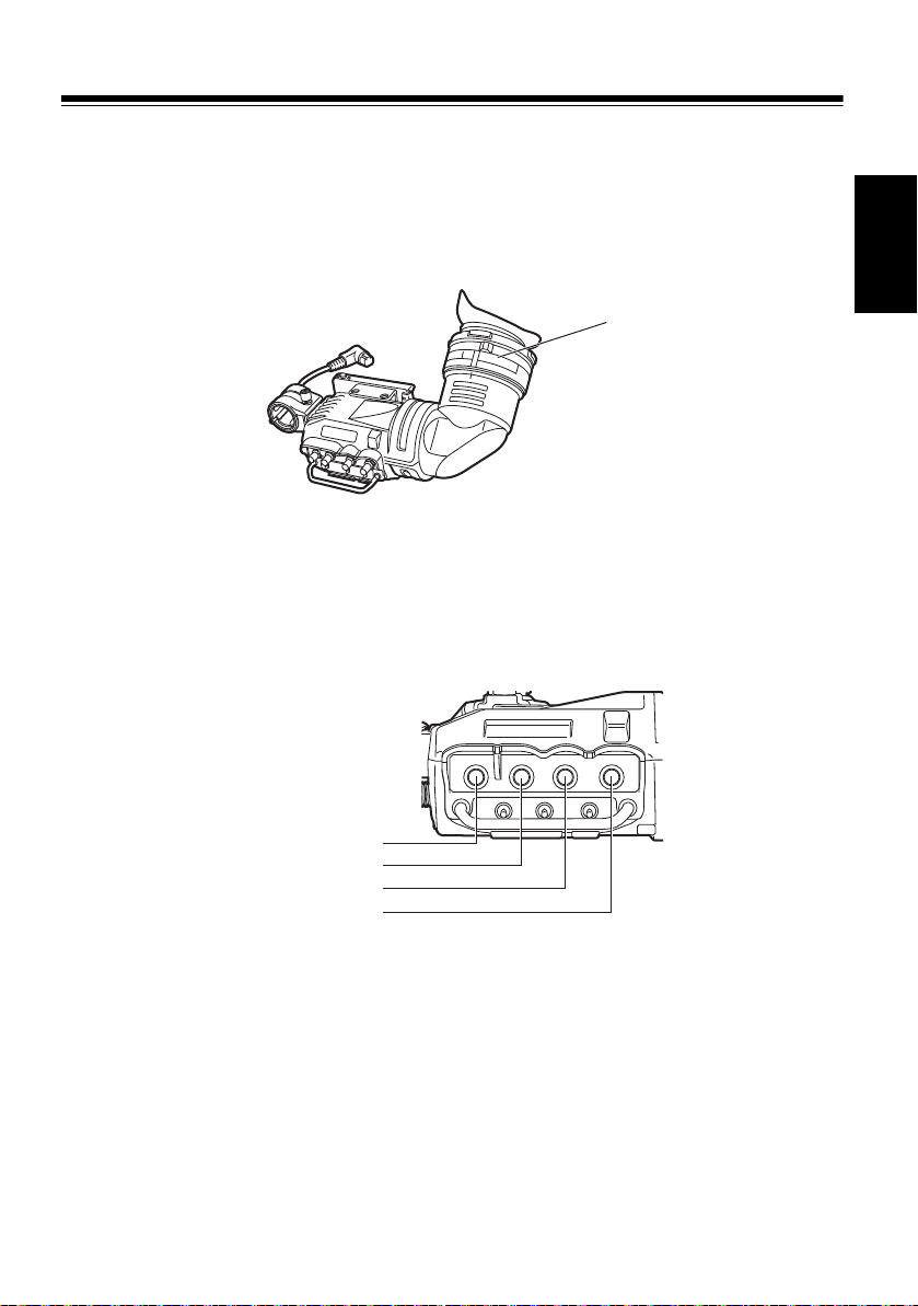
Viewfinder Stopper
9
This is used to attach and detach the viewfinder.
Eyepiece
:
; Back Tally Lamp
Lights when the camera is shooting. Also, flashes on and off as a warning indication, in
the same manner as the REC lamp inside the viewfinder.
The back tally lamp is hidden when the lever is in the OFF position.
Diopter Adjuster Ring
<
Adjust this control to match the vision of the person using the camera so that the image
on the screen in the viewfinder is as clear as possible.
= Connection Plug
> Lock Ring
? Microphone Holder
@ Slide rail
E-5
Page 7
Parts and Their Functions (Continued)
TALLY / REC
BATT
SAVE
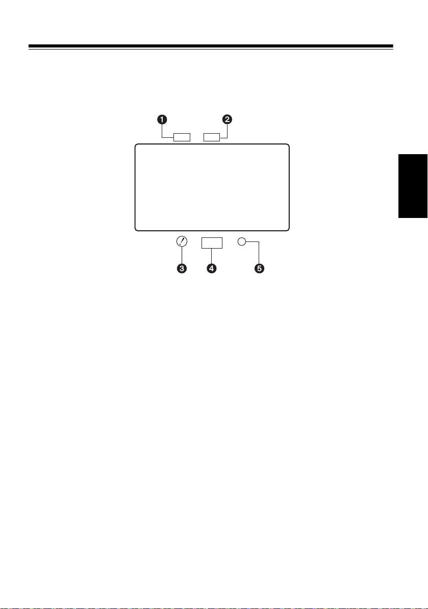
Internal LEDs
Indicators and displayed screen content are different depending on the camera used.
Refer to the instruction manual of the camera for details.
1
Green TALLY Indicator
Lights in green when a green TALLY signal is received from the camera control unit.
TALLY/REC Indicator
2
Lights in red during the recording, or when the red TALLY signal is received from the
camera control unit. Flashes in red when there is an error.
3
! Indicator
Light condition for ! Indicator can be set with the ! LED item of the menu in the camera.
This can be used to prevent erroneous operation for various operations.
BATT Indicator
4
Lights or flashes depending on the condition of the battery. Condition to flash or light is
different depending on the camera setting.
SAVE Indicator
5
Lights when the SAVE switch of the camera is ON, or when the VTR SAVE/STBY
switch of the camera is set to SAVE.
ENGLISH
E-6
Page 8
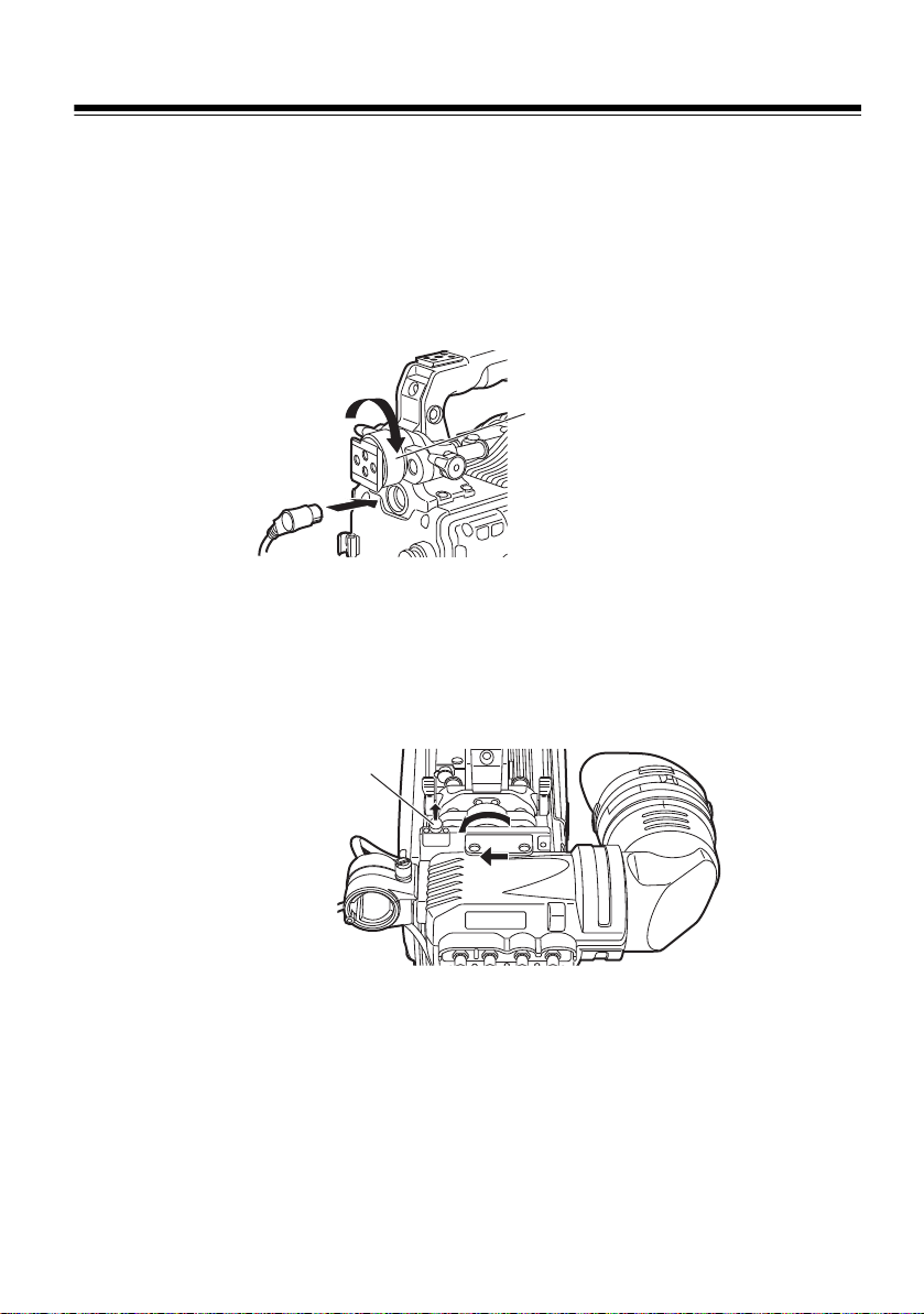
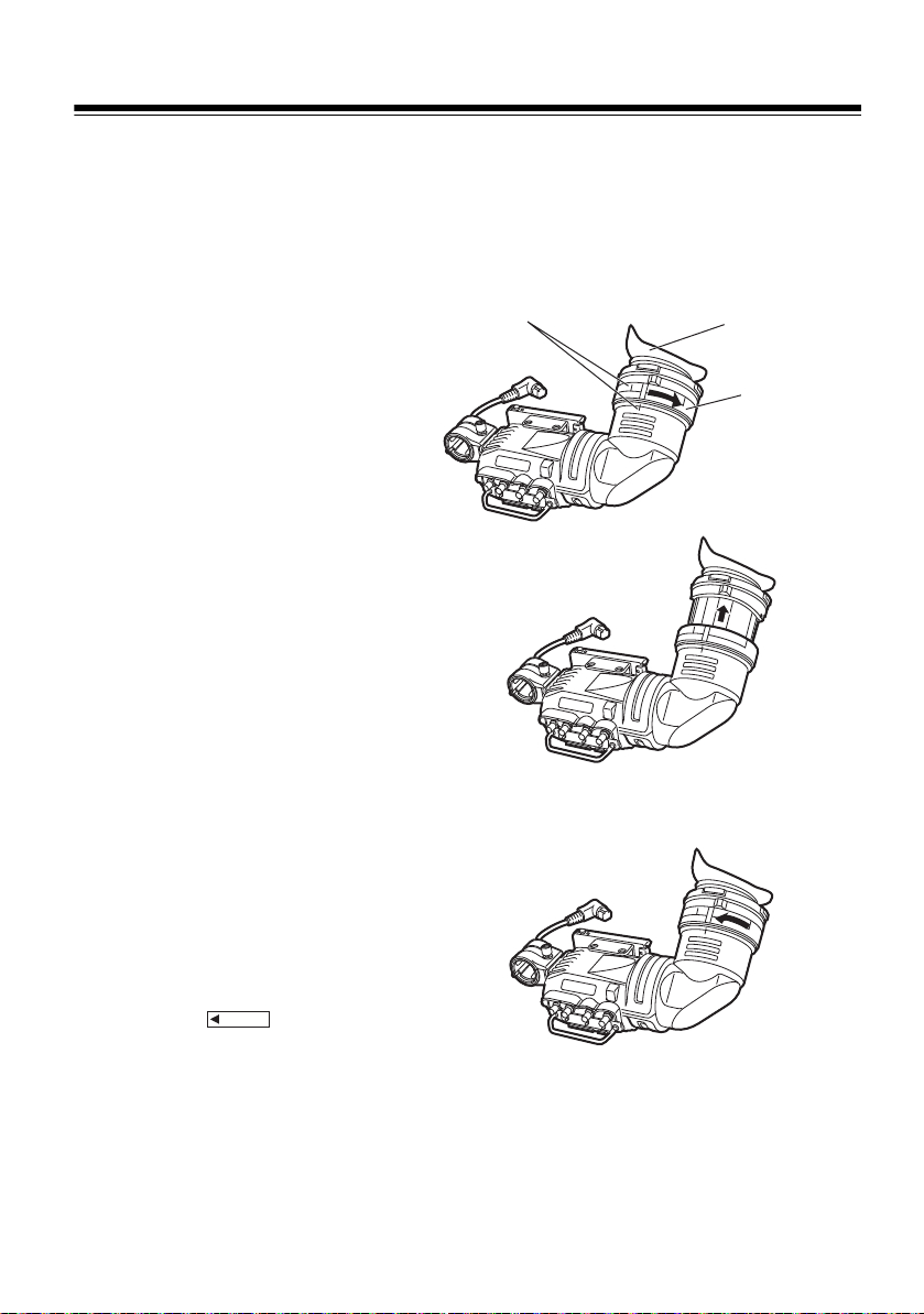
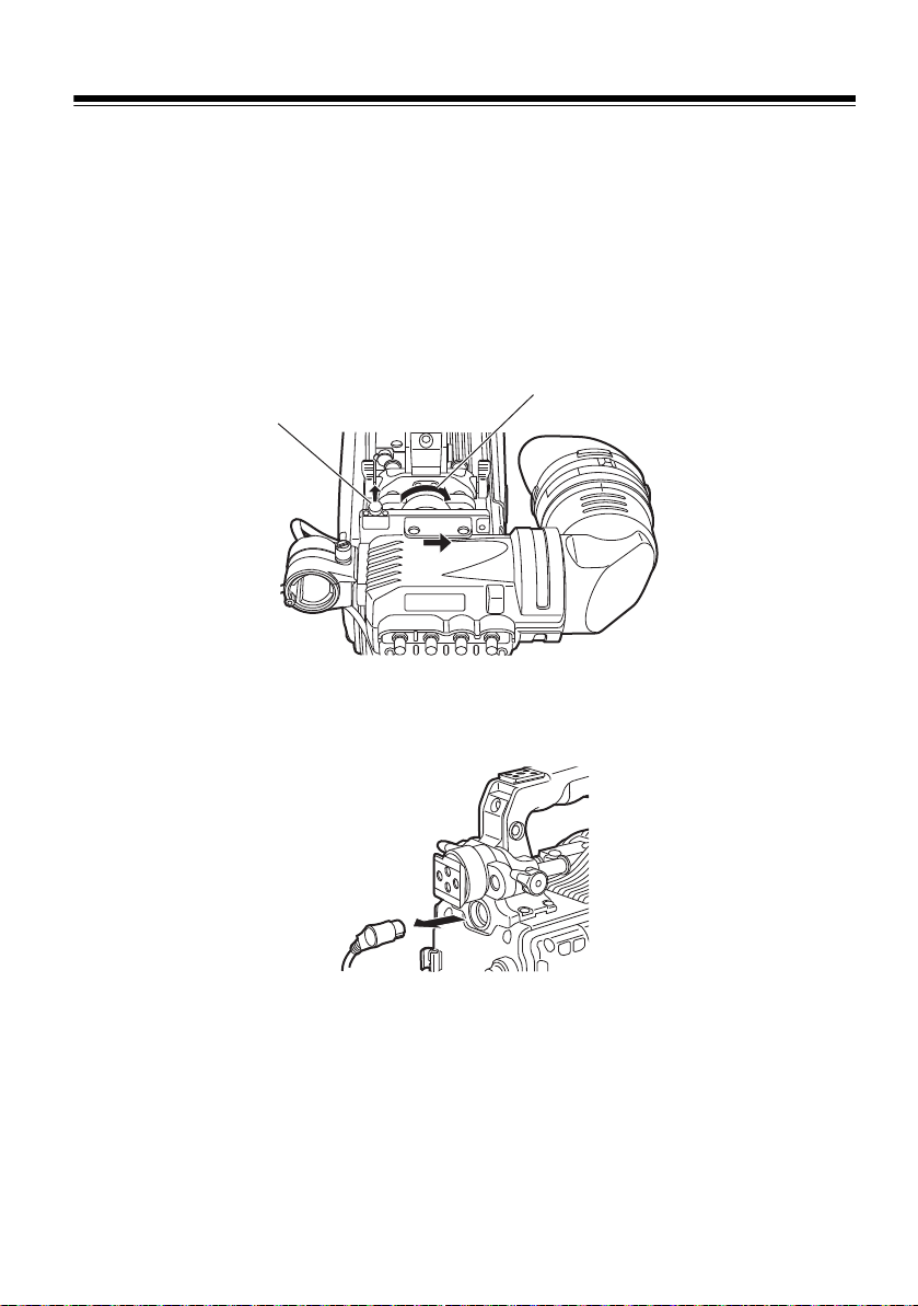
Adjusting the Viewfinder
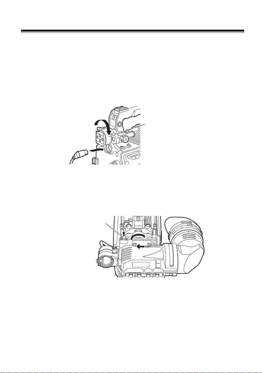
Loosen the ring.
Viewfinder left-right
position anchoring ring
Viewfinder stopper
Attaching the Viewfinder
1 Confirm that the POWER switch of the camera is “OFF”.
2 Insert the plug into the connection jack of the viewfinder.
<Note>
Be sure to insert the plug all the way into the connection jack.
3 Loosen the viewfinder left-right position anchoring ring.
4 While pulling up the viewfinder stopper, attach the viewfinder by sliding it in the
direction of the arrow. After attaching the viewfinder, check that the stopper is in
place.
5 Tighten the viewfinder left-right position anchoring ring.
E-7
Page 9
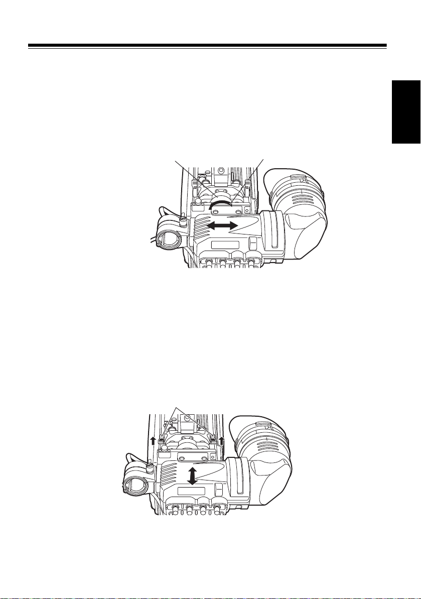
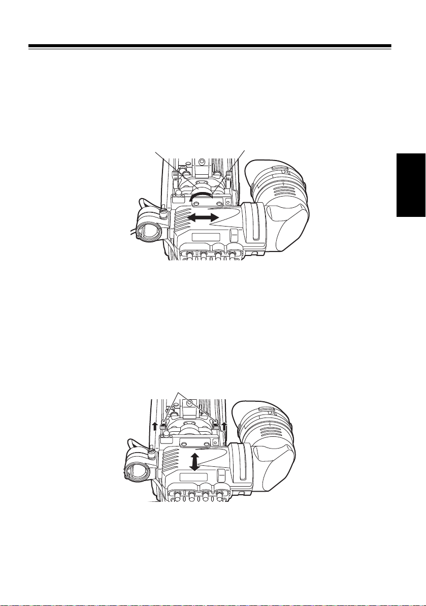
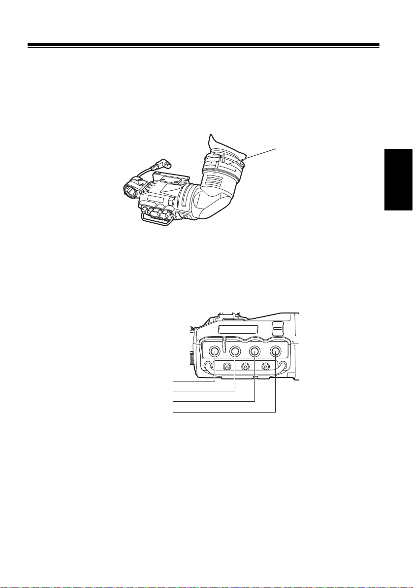
Adjusting the Viewfinder (Continued)
Viewfinder left-right
position anchoring ring
Tighten the ring.
Viewfinder front-back position anchoring lever
Adjusting the Viewfinder’s left-right position
1 Loosen the viewfinder left-right position anchoring ring.
2 Slide the viewfinder to the left or right, and adjust it to a position that allows easy
viewing.
3 Tighten the viewfinder left-right position anchoring ring.
Adjusting the Viewfinder’s front-back position
ENGLISH
1 Loosen the viewfinder front-back position anchoring lever.
2 Slide the viewfinder to the front or back, and adjust it to a position that allows easy
viewing.
3 Tighten the viewfinder front-back position anchoring lever.
E-8
Page 10
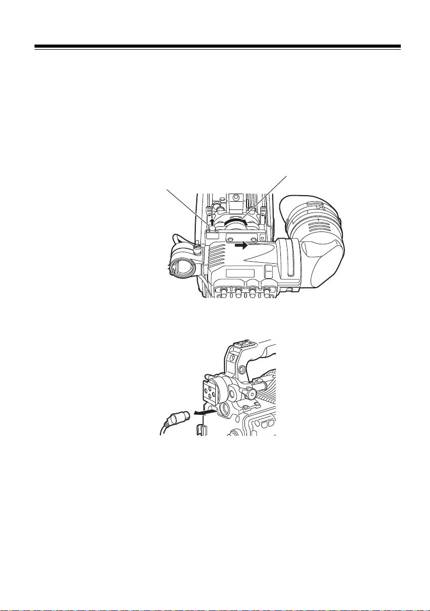
Adjusting the Viewfinder (Continued)
Viewfinder stopper
Loosen the ring.
Detaching the Viewfinder
1 Confirm that the POWER switch of the camera is “OFF”.
2 Loosen the viewfinder left-right position anchoring ring.
3 While pulling up the viewfinder stopper, remove the viewfinder by sliding it in the
direction of the arrow.
4 Release the viewfinder cable and mic cable from the cable clamps, and disconnect
the cables.
E-9
Page 11
Adjusting the Viewfinder (Continued)
Diopter adjustment ring
PEAKING control
CONTRAST control
BRIGHT control
CHROMA
CHROMA control
Diopter Adjustment
1 Set the POWER switch of the camera to “ON”. A picture will appear in the viewfinder.
2 Turn the diopter adjustment ring to adjust the diopter so that the viewfinder picture
can be clearly seen.
Screen Adjustment
Adjust the condition of the viewfinder screen.
Brightness: Adjust the BRIGHT control.
Contrast: Adjust the CONTRAST control.
Chroma: Adjust the CHROMA control.
Contour: Adjust the PEAKING control.
ENGLISH
PEAKING CONTRAST BRIGHT
1 Set the POWER switch of the camera to “ON”.
2 Set the OUTPUT switch of the camera to “BAR”.
3 Adjust the brightness and contrast of the image by turning the BRIGHT and
CONTRAST controls on the viewfinder, and the chroma of the image by the
CHROMA control.
Turning the PEAKING control makes the picture appear sharper.
A sharper picture facilitates focusing the lens.
<Note>
Primary colors (red, blue and green) may be seen when moving eye position in the
viewfinder. (This is not a failure.)
E-10
Page 12
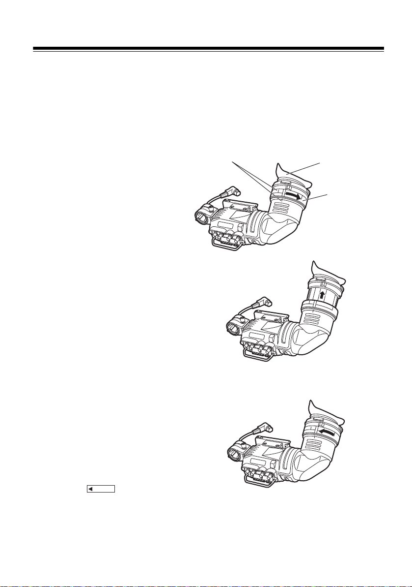
Cleaning the Eyepiece
Eyepiece
Lock ring
Alignment marks
Remove the eyepiece to clean off any dust that got on the LCOS panel screen or mirror.
<Note>
Do not wipe the mirror surface under any circumstances as it has been specially treated.
Dust which has adhered to the mirror should be blown away with a blower, etc.
1 Turn the lock ring as far as
possible in the counterclockwise
direction to line up the alignment
marks on the lock ring and
viewfinder barrel.
2 Detach the eyepiece.
Remounting the Eyepiece
1 Line up the alignment marks on
the lock ring and the viewfinder
barrel and slide the eyepiece
back into place.
2 Turn the lock ring clockwise as
far as the position.
E-11
LOCK
Page 13
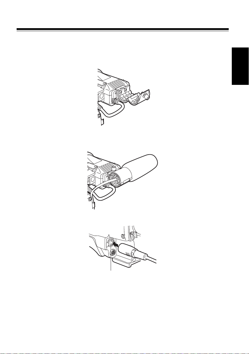
Attaching the Microphone
Viewfinder
Microphone holder
MIC IN jack
Follow the steps below to install the AJ-MC700P or the AJ-MC900G microphone kit (sold
separately).
1 Open the microphone holder.
2 Attach the microphone.
ENGLISH
3 Plug the microphone connector cable into the MIC IN jack.
E-12
Page 14

Specifications
Power supply: DC 12 V (supplied by camera)
Power consumption: 5.0 W
indicates safety information.
Display panel:
1-inch LCOS panel
Image system:
Compatible with automatic switching to the following images
1080/50i, 1080/59.94i, 1080/60i, 720/59.94P, 720/60P
External adjustment controls:
Controls
(BRIGHT, CONTRAST, CHROMA, PEAKING)
Switches
(TALLY HIGH/OFF/LOW, ZEBRA ON/OFF, CHROMA ON/OFF)
Allowable temperature range:
–10 °C to 45 °C (14 °F to 113 °F)
Allowable humidity range:
85% or less (no condensation)
External dimensions (W a H a D):
240 mm a 80 mm a 206 mm
(9-1/2 inches a 3-3/16 inches a 8-1/8 inches)
Weight: 770 g (1.70 lb)
Weight and dimentions when shown are approximately.
Specifications are subject to change without notice.
E-13
Page 15

Information on Disposal for Users of Waste Electrical &
Electronic Equipment (private households)
This symbol on the products and/or accompanying documents means
that used electrical and electronic products should not be mixed with
general household waste.
For proper treatment, recovery and recycling, please take these
products to designated collection points, where they will be accepted
on a free of charge basis. Alternatively, in some countries you may be
able to return your products to your local retailer upon the purchase of
an equivalent new product.
Disposing of this product correctly will help to save valuable resources and prevent any
potential negative effects on human health and the environment which could otherwise
arise from inappropriate waste handling. Please contact your local authority for further
details of your nearest designated collection point.
Penalties may be applicable for incorrect disposal of this waste, in accordance with
national legislation.
For business users in the European Union
If you wish to discard electrical and electronic equipment, please contact your dealer or
supplier for further information.
Information on Disposal in other Countries outside the European Union
This symbol is only valid in the European Union.
If you wish to discard this product, please contact your local authorities or dealer and ask
for the correct method of disposal.
ENGLISH
E-14
Page 16
DEUTCH
Bitte lesen!
_ Öffnen Sie nicht das Gerät durch Abschrauben von Gehäuseteilen.
Im Geräteinneren befinden sich keine Teile, die vom Benutzer gewartet werden können.
Wartungs- und Reparaturarbeiten grundsätzlich autorisiertem Kundendienstpersonal
überlassen.
WARNUNG:
z ZUR REDUZIERUNG DER GEFAHR VON BRAND UND ELEKTRISCHEM SCHLAG
DIESES GERÄT WEDER NÄSSE NOCH FEUCHTIGKEIT AUSSETZEN.
z UM BRAND- ODER STROMSCHLAGGEFAHR ZU REDUZIEREN, MUSS DIESES
GERÄT VON ALLEN FLÜSSIGKEITEN FERNGEHALTEN WERDEN. VERMEIDEN SIE
GEBRAUCH UND LAGERUNG DES GERÄTES AN ORTEN, AN DENEN DIE GEFAHR
BESTEHT, DASS ES MIT FLÜSSIGKEITEN BETROPFT ODER BESPRITZT WIRD, UND
STELLEN SIE KEINE FLÜSSIGKEITSBEHÄLTER AUF DAS GERÄT.
Vorsicht:
z Richten Sie das Okular nicht direkt auf die Sonne.
ist die Sicherheitsinformation.
Inhalt
Bitte lesen!......................................................................................................... 1
Merkmale............................................................................................................ 2
Teile und ihre Funktionen................................................................................. 2
Einstellen des Suchers ..................................................................................... 5
Anbringen des Suchers.................................................................................................5
Einstellen der Querposition des Suchers ......................................................................6
Einstellen der Längsposition des Suchers ....................................................................6
Abnehmen des Suchers................................................................................................7
Dioptrieneinstellung.......................................................................................................8
Sucherschirmeinstellung ...............................................................................................8
Reinigen des Sucherokulars ............................................................................ 9
Anbringen des Mikrofons ............................................................................... 10
Technische Daten............................................................................................ 11
G-1
Page 17
Merkmale
z Es ist mit dem Multi-Format kompatibel (1080i/720P).
z Ein hoch auflösendes Farb-LCD-Panel zeigt genaue Bilder an, was das Fokussieren
einfach macht.
z Mit dem 1-Zoll LCOS-Panel wurden eine schnelle Ansprache und eine hohe Auflösung
erreicht, vergleichbar mit einem CRT.
z Dieses Gerät hat die gleiche Größe wie ein konventioneller Schwarzweiß-HD-Sucher,
was einen Austausch ohne eine Veränderung ermöglicht.
(Dieses Gerät ist mit den AJ-HDX900 und Serien AJ-HPX vergleichbar. Fragen Sie Ihren
Händler bezüglich anderer Kameras)
z Es ist möglich, ganz einfach zwischen den Farb- und den Schwarzweißmodi zu
wechseln, indem man den CHROMA-Schalter betätigt.
Teile und ihre Funktionen
DEUTSCH
CHROMA
PEAKING CONTRAST BRIGHT
OFF
1 CHROMA-Schalter
Schaltet im Sucher die Bildanzeige zwischen Farb- und Schwarzweißanzeige um.
ON: Zeigt Farbbilder.
OFF: Zeigt Schwarzweißbilder.
2 Zebramusterschalter [ZEBRA]
Dient zum Anzeigen eines Zebramusters im Sucher.
ON: Ein Zebramuster wird angezeigt.
OFF: Kein Zebramuster wird angezeigt.
Die Details der Anzeige, z.B. die Art des Zebramusters, hängen von der mit dem Sucher
verwendeten Kamera ab. Einzelheiten sind der Bedienungsanleitung der Kamera zu entnehmen.
ON
G-2
Page 18

Teile und ihre Funktionen (Fortsetzung)
3 Signallampenschalter [TALLY]
Steuert die vordere Signallampe.
HIGH: Erhöht die Helligkeit der vorderen Signallampe.
OFF: Schaltet die Signallampe aus.
LOW: Verringert die Helligkeit der vorderen Signallampe.
Regler PEAKING
4
Dient zur Einstellung der Bildkonturen im Sucher, um die Scharfeinstellung zu erleichtern.
Die Einstellung dieses Reglers hat keinen Einfluß auf das Ausgangssignal der Kamera.
5 Regler CHROMA
Stellt Sie die Farbsättigung des Bildes im Sucher ein. Die Einstellung dieses Reglers
hat keinen Einfluß auf das Ausgangssignal der Kamera.
<Hinweis>
In Umgebungen mit niedriger Temperatur, kann es sein, dass die Farben, sofort nach
dem Anstellen des Stroms, im wiedergegeben Bild etwas schwächer dargestellt werden.
6 Regler CONTRAST
Dient zur Einstellung des Sucherschirmkontrastes. Die Einstellung dieses Reglers hat
keinen Einfluß auf das Ausgangssignal der Kamera.
Regler BRIGHT
7
Dient zur Einstellung der Helligkeit des Sucherschirms. Die Einstellung dieses Reglers
hat keinen Einfluß auf das Ausgangssignal der Kamera.
Vordere Signallampe
8
Leuchtet auf, wenn die Kamera aufnimmt und der Schalter TALLY auf HIGH oder LOW steht.
Die Lampe blinkt außerdem als Warnsignal, wie die Lampe REC im Sucher.
Die Helligkeit der vorderen Signallampe wird durch die Einstellung des Schalters
TALLY (HIGH oder LOW) beeinflußt.
9 Sucheranschlag
Dient zum Anbringen und Abnehmen des Suchers.
Okular
:
; Rückwärtige Signallampe
Leuchtet auf, wenn die Kamera aufnimmt. Die Lampe blinkt außerdem als Warnsignal,
wie die Lampe REC im Sucher.
Die rückwärtige Signallampe ist verdeckt, wenn sich der Hebel in der Stellung OFF
befindet.
Dioptrien-Einstellring
<
Dient zur Anpassung des Suchers an die Sehkraft des jeweiligen Benutzers der
Kamera, um ein möglichst scharfes Sucherbild zu erhalten.
= Anschlußstecker
> Verriegelungsring
? Mikrofonhalter
@ Gleitschiene
G-3
Page 19
Teile und ihre Funktionen (Fortsetzung)
TALLY / REC
BATT
SAVE
Interne LEDs
Inhalte der Anzeigen und Bildschirmanzeigen unterscheiden sich davon, welche
Kamera benutzt wird.
Einzelheiten sind der Bedienungsanleitung der Kamera zu entnehmen.
Grüne TALLY-Anzeige
1
Leuchtet grün auf, wenn ein grünes TALLY-Signal von der Bedienungseinheit der
Kamera empfangen wird.
TALLY/REC-Anzeige
2
Leuchtet während der Aufnahme rot auf oder wenn das rote TALLY-Signal von der
Bedienungseinheit der Kamera empfangen wird. Leuchtet rot auf, wenn ein Fehler
auftritt.
3 !-Anzeige
Lichtbedingungen für die !-Anzeige können mit dem ! LED-Element des Kameramenüs
eingestellt werden. Dies kann verwendet werden, um vor einem fehlerhaften Betrieb
bei verschiedenen Operationen zu schützen.
4 BATT-Anzeige
Leuchtet oder blinkt abhängig davon, wie sich der Zustand der Batterie befindet. Die
Bedingung, ob es blinkt oder leuchtet, hängt von der Kameraeinstellung ab und kann
unterschiedlich sein.
SAVE-Anzeige
5
Leuchtet auf, wenn der SAVE-Schalter der Kamera auf ON steht, oder wenn der VTR
SAVE/STBY-Schalter der Kamera auf SAVE gestellt wurde.
DEUTSCH
G-4
Page 20
Einstellen des Suchers
Den Ring lösen.
Querpositions-Feststellring
des Suchers
Sucheranschlag
Anbringen des Suchers
1 Sicherstellen, daß sich der Schalter POWER der Kamera in der AUS-Stellung
befindet.
2 Den Stecker in die Anschlußbuchse des Suchers einführen.
<Hinweis>
Führen Sie den Stecker bis zum Anschlag in die Anschlußbuchse ein.
3 Lösen Sie den Querpositions-Feststellring des Suchers.
4 Bringen Sie den Sucher durch Einschieben in Pfeilrichtung an, während Sie den
Sucheranschlag hochziehen. Nachdem der Sucher angeschlossen wurde,
überprüfen Sie, ob sich der Sucheranschlag an der richtigen Stelle befindet.
5 Ziehen Sie den Querpositions-Feststellring des Suchers an.
G-5
Page 21
Einstellen des Suchers (Fortsetzung)
Querpositions-Feststellring des Suchers
Den Ring anziehen.
Längspositions-Feststellhebel des Suchers
Einstellen der Querposition des Suchers
1 Lösen Sie den Querpositions-Feststellring des Suchers.
2 Schieben Sie den Sucher nach links oder rechts, um seine Position so einzustellen,
dass der Suchermonitor bequem ablesbar ist.
3 Ziehen Sie den Querpositions-Feststellring des Suchers an.
Einstellen der Längsposition des Suchers
DEUTSCH
1 Lösen Sie den Längspositions-Feststellhebel des Suchers.
2 Schieben Sie den Sucher nach vorn oder hinten, um seine Position so einzustellen,
dass der Suchermonitor bequem ablesbar ist.
3 Ziehen Sie den Längspositions-Feststellhebel des Suchers an.
G-6
Page 22
Einstellen des Suchers (Fortsetzung)
Sucheranschlag
Den Ring lösen.
Abnehmen des Suchers
1 Sicherstellen, daß sich der Schalter POWER der Kamera in der AUS-Stellung
befindet.
2 Lösen Sie den Querpositions-Feststellring des Suchers.
3 Entfernen Sie den Sucher durch Schieben in Pfeilrichtung, während Sie den
Sucheranschlag hochziehen.
4 Lösen Sie das Sucherkabel und das Mikrofonkabel aus den Kabelklemmen, und
trennen Sie die Kabel ab.
G-7
Page 23
Einstellen des Suchers (Fortsetzung)
Dioptrien-Einstellring
PEAKING CONTRAST BRIGHT
CHROMA
Regler PEAKING
Regler CONTRAST
Regler BRIGHT
Regler CHROMA
Dioptrieneinstellung
1 Den Schalter POWER der Kamera auf die EIN-Stellung stellen. Ein Bild erscheint im
Sucher.
2 Das Okular durch Drehen des Dioptrien-Einstellrings so einstellen, daß das
Sucherbild scharf ist.
Sucherschirmeinstellung
Den Zustand des Sucherschirms einstellen.
Helligkeit: Den Regler BRIGHT drehen.
Kontrast: Den Regler CONTRAST drehen.
Sättigung: Den Regler CHROMA drehen.
Kontur: Den Regler PEAKING drehen.
DEUTSCH
1 Den Schalter POWER der Kamera auf die EIN-Stellung stellen.
2 Den Schalter OUTPUT der Kamera auf “BAR” stellen.
3 Stellen Sie Helligkeit und Kontraste des Bildes ein, indem Sie die Regler BRIGHT
und CONTRAST am Sucher drehen. Farbton und Sättigung des Bildes (Chroma)
stellen Sie mit dem Regler CHROMA ein.
Die Konturenschärfe durch Drehen des Reglers PEAKING erhöhen.
Ein schärferes Sucherbild erleichtert das Fokussieren des Objektivs.
<Hinweis>
Beim Bewegen der Augenposition im Sucher sind Primärfarben sichtbar (Rot, Blau,
Grun). (Hierbei handelt es sich nicht um einen Fehler.)
G-8
Page 24
Reinigen des Sucherokulars
Okular
Verriegelungsring
Ausrichtmarkierungen
LOCK
Entfernen Sie das okular, um Staub zu entfernen, der auf den LCOS-Panel des
Bildschirms oder des Spiegels gelangt ist.
<Hinweis>
Die Spiegeloberfläche darf unter keinen Umständen abgewischt werden, da sie speziell
vergütet ist. Am Spiegel haftender Staub sollte mit einem Blasepinsel oder dergleichen
entfernt werden.
1 Den Verriegelungsring so weit
wie möglich nach rechts drehen,
um die Ausrichtmarkierungen an
Verriegelungsring und
Suchertubus zur Deckung zu
bringen.
2 Das Okular abnehmen.
Anbringen des Okulars
1 Die Ausrichtmarkierungen an
Verriegelungsring und
Suchertubus zur Deckung
bringen, und das Okular wieder
einschieben.
2 Den Verriegelungsring bis zur
Position nach rechts
drehen.
G-9
Page 25

Anbringen des Mikrofons
Sucher
Mikrofonhalter
Buchse MIC IN
Führen Sie die folgenden Schritte aus, um den Mikrofonsatz AJ-MC700P oder AJMC900G (getrennt erhältlich) zu montieren.
1 Den Mikrofonhalter öffnen.
2 Das Mikrofon anbringen.
DEUTSCH
3 Den Stecker des Mikrofonkabels an die Buchse MIC IN anschließen.
G-10
Page 26

Technische Daten
Stromversorgung: 12 V Gleichspannung (Versorgung durch Kamera)
Leistungsaufnahme: 5,0 W
ist die Sicherheitsinformation.
Anzeige:
1-Zoll LCOS-Panel
Bildsystem:
Kompatibel mit automatischer Umschaltung auf folgende Bilder
1080/50i, 1080/59,94i, 1080/60i, 720/59,94P, 720/60P
Externe Regler und Schalter:
Regler
(BRIGHT, CONTRAST, CHROMA, PEAKING)
Schalter
(TALLY HIGH/OFF/LOW, ZEBRA ON/OFF, CHROMA ON/OFF)
Zulässiger Temperaturbereich:
–10 °C bis 45 °C
Zulässiger Luftfeuchtigkeitsbereich:
85% oder weniger (keine Kondensation)
Außenabmessungen (BaHaT):
240 mm a 80 mm a 206 mm
Gewicht: 770 g
Bei den Angaben zu Gewicht und Abmessungen handelt es sich um Näherungswerte.
Änderungen der technischen Daten bleiben im Sinne der ständigen Produktverbesserung
vorbehalten.
G-11
Page 27

Benutzerinformationen zur Entsorgung von elektrischen und
elektronischen Geräten (private Haushalte)
Dieses Symbol auf Produkten und/oder begleitenden Dokumenten
bedeutet, dass verbrauchte elektrische und elektronische Produkte
nicht mit gewöhnlichem Haushaltsabfall vermischt werden sollen.
Bringen Sie zur ordnungsgemäßen Behandlung, Rückgewinnung und
Recycling diese Produkte zu den entsprechenden Sammelstellen, wo
sie ohne Gebühren entgegengenommen werden. In einigen Ländern
kann es auch möglich sein, diese Produkte beim Kauf eines
entsprechenden neuen Produkts bei Ihrem örtlichen Einzelhändler
abzugeben.
Die ordnungsgemäße Entsorgung dieses Produkts dient dem Umweltschutz und
verhindert mögliche schädliche Auswirkungen auf Mensch und Umgebung, die aus einer
unsachgemäßen Handhabung von Abfall entstehen können. Genauere Informationen
zur nächstgelegenen Sammelstelle erhalten Sie bei Ihrer Gemeindeverwaltung.
In Übereinstimmung mit der Landesgesetzgebung können für die unsachgemäße
Entsorgung dieser Art von Abfall Strafgebühren erhoben werden.
Für Geschäftskunden in der Europäischen Union
Bitte treten Sie mit Ihrem Händler oder Lieferanten in Kontakt, wenn Sie elektrische und
elektronische Geräte entsorgen möchten. Er hält weitere Informationen für sie bereit.
Informationen zur Entsorgung in anderen Ländern außerhalb der Europäischen
Union
Dieses Symbol ist nur in der Europäischen Union gültig.
Bitte treten Sie mit Ihrer Gemeindeverwaltung oder Ihrem Händler in Kontakt, wenn Sie
dieses Produkt entsorgen möchten, und fragen Sie nach einer Entsorgungsmöglichkeit.
DEUTSCH
G-12
Page 28

FRANÇAIS
Lire ces informations en premier !
_ Ne pas dévisser le couvercle.
Il ne se trouve à l’intérieur aucune pièce qui puisse être réparée par l’utilisateur.
Confier toute réparation à un personnel qualifié.
AVERTISSEMENT:
z POUR RÉDUIRE LES RISQUES D’INCENDIE OU DE CHOC ÉLECTRIQUE, ÉVITEZ
D’EXPOSER CET APPAREIL À LA PLUIE OU À L’HUMIDITÉ.
z POUR RÉDUIRE TOUT RISQUE DE FEU OU DE CHOC ÉLECTRIQUE, ÉLOIGNER
L’APPAREIL DES LIQUIDES - UTILISER ET RANGER UNIQUEMENT DANS UN
ENDROITNE RISQUANT PAS DE RECEVOIR DES GOUTTES OU D’ÊTRE ASPERGÉ DE
LIQUIDES, ET NE PAS METTRE DE RÉCIPIENT RENFERMANT DES LIQUIDES SUR LE
DESSUS DE L’APPAREIL.
Attention:
z Veiller à ne pas diriger l’oeilleton directement sur le soleil.
Pour le Canada
NOTIFICATION (Canada)
Cet appareil numéique de la classe B est conforme à la norme NMB-003 du Canada.
Informations concernant la sécurité.
F-1
Page 29

Table des matières
Lire ces informations en premier ! .................................................................. 1
Caractéristiques ................................................................................................ 2
Les commandes et leurs fonctions ................................................................. 3
Réglage du viseur ............................................................................................. 5
Montage du viseur.........................................................................................................5
Réglage de la position gauche-droite du viseur ............................................................6
Réglage de la position avant-arrière du viseur..............................................................6
Retrait du viseur ............................................................................................................7
Réglage de la correction dioptrique...............................................................................8
Réglage de l’écran.........................................................................................................8
Nettoyage de l’oculaire ..................................................................................... 9
Montage du microphone................................................................................. 10
Fiche technique............................................................................................... 11
Caractéristiques
z Il est compatible avec le Multi-format (1080i/720P).
z L’écran LCD couleur haute résolution affiche des images fines permettant une mise au
point facile.
z Grâce à l’écran LCOS de 1 pouce, il a réalisé une réponse rapide et une haute
résolution équivalentes à un CRT.
z Cet appareil fait la même taille que le viseur B&W HD conventionnel pouvant être donc
remplacé sans modification.
(Cet appareil est compatible avec les AJ-HDX900 et séries AJ-HPX. Consultez le
revendeur pour les autres appareils)
z Il est possible de basculer entre les modes couleurs et B&W à l’aide du commutateur de
saturation.
FRANÇAIS
F-2
Page 30

Les commandes et leurs fonctions
ON
OFF
CHROMA
PEAKING CONTRAST BRIGHT
1 Commutateur de saturation
(CHROMA)
Bascule l’affichage des images entre
Couleurs et B&W sur le viseur.
ON: Affiche les images en couleur.
Affiche les images en noir et blanc.
OFF:
2 Commutateur de motif de
zébrures (ZEBRA)
Il permet d’afficher un motif de zébrures
dans le viseur.
ON: Affiche un motif de zébrures.
OFF: N’affichage pas de motif de
zébrures.
Les détails de l’affichage, comme le type
du motif de zébrures, varient en fonction
de la caméra utilisée. Pour les détails, voir
le mode d’emploi de la caméra.
3 Commutateur de signalisation
(TALLY)
Permet de commander le témoin de
signalisation avant.
HIGH: Rend le voyant de signalisation
avant plus brillant.
OFF: Eteint le voyant de signalisation.
LOW: Rend le voyant de signalisation
avant moins brillant.
Commande PEAKING
4
Il permet de régler les contours de
l’image dans le viseur de façon à les
rendre plus nets. Le réglage de cette
commande est sans effet sur le signal
de sortie de la caméra.
Commande CHROMA
5
Règle la saturation de la couleur pour
l’image du viseur. Le réglage de cette
commande est sans effet sur le signal
de sortie de la caméra.
<Remarque>
Dans des environnements où la
température est basse, les couleurs de
l’image affichée peuvent être plus pâles
aussitôt après la mise sous tension.
Commande CONTRAST
6
Il permet de régler le contraste de
l’écran dans le viseur. Le réglage de
cette commande est sans effet sur le
signal de sortie de la caméra.
Commande BRIGHT
7
Il permet de régler la luminosité de
l’écran dans le viseur. Le réglage de
cette commande est sans effet sur le
signal de sortie de la caméra.
F-3
Page 31

Les commandes et leurs fonctions (suite)
TALLY / REC
BATT
SAVE
8 Voyant de signalisation avant
S’allume pendant la prise de vues
lorsque le commutateur TALLY est réglé
sur HIGH ou LOW.
Par ailleurs, il clignote à titre
d’avertissement, de la même manière
que le voyant REC dans le viseur.
La luminosité du voyant de signalisation
avant est contrôlée par le réglage du
commutateur TALLY (HIGH ou LOW).
Butée du viseur
9
Elle permet de fixer et de retirer le viseur.
: Œilleton
; Voyant de signalisation arrière
S’allume pendant la prise de vues. Par
ailleurs, il clignote à titre d’avertissement,
de la même manière que le voyant REC
dans le viseur.
Le voyant de signalisation arrière est
dissimulé lorsque le levier est en position
OFF.
< Bague de correction dioptrique
Cette commande permet d’adapter le
viseur à la vue de l’opérateur, de façon
que l’image dans l’écran du viseur soit
la plus nette possible.
= Fiche de raccordement
> Bague de verrouillage
? Support de microphone
@ Rail coulissant
LED internes
Les témoins et le contenu de l’écran
affiché sont différents selon l’appareil
utilisé.
Pour les détails, voir le mode d’emploi
de la caméra.
Témoin vert TALLY
1
S’allume en vert lorsqu’un signal TALLY
est reçu par l’unité de contrôle de
l’appareil.
Témoin TALLY/REC
2
S’allume en rouge pendant l’enregistrement
ou lorsque le signal rouge TALLY est reçu
par l’unité de contrôle de l’appareil. Clignote
en rouge en cas d’erreur.
3 Témoin !
La condition d’allumage du témoin ! peut
être paramétré à l’aide de l’élément
! LED du menu dans l’appareil. Cela est
utile pour prévenir toutes opérations
erronées pour diverses opérations.
4 Témoin BATT
S’allume ou clignote en fonction de
l’état de la batterie. Le prérequis pour
que le témoin clignote ou s’allume
dépend du réglage de l’appareil.
5 Témoin SAVE
S’allume lorsque le commutateur SAVE
de l’appareil est sur ON ou lorsque le
commutateur VTR SAVE/STBY de
l’appareil est réglé sur SAVE.
FRANÇAIS
F-4
Page 32

Réglage du viseur
Desserrer la bague.
Bague d’ancrage de la position
gauche-droite du viseur
Butée du viseur
Montage du viseur
1 Vérifier que l’interrupteur POWER de la caméra est éteint (“OFF”).
2 Insérer la fiche dans la prise de raccordement du viseur.
<Remarque>
Bien insérer la fiche à fond dans la prise de raccordement.
3 Desserrer la bague d’ancrage de la position gauche-droite du viseur.
4 Tout en soulevant la butée du viseur, fixer le viseur en le glissant dans le sens de la
flèche. Après avoir fixé le viseur, vérifiez que la butée est en place.
5 Serrer la bague d’ancrage de la position gauche-droite du viseur.
F-5
Page 33

Réglage du viseur (suite)
Bague d’ancrage de la position
gauche-droite du viseur
Serrer la bague.
Lift d’ancrage de la position avant-arrière du viseur
Réglage de la position gauche-droite du viseur
1 Desserrer la bague d’ancrage de la position gauche-droite du viseur.
2 Glisser le viseur vers la gauche ou vers la droite, et le régler sur la position
permettant une vue facile des données sur l’écran.
3 Serrer la bague d’ancrage de la position gauche-droite du viseur.
Réglage de la position avant-arrière du viseur
1 Desserrer la lift d’ancrage de la position avant-arrière du viseur.
2 Glisser le viseur vers l’avant ou vers l’arrière, et le régler sur la position permettant
une vue facile des données sur l’écran.
3 Serrer la lift d’ancrage de la position avant-arrière du viseur.
FRANÇAIS
F-6
Page 34

Réglage du viseur (suite)
Butée du viseur
Desserrer la bague.
Retrait du viseur
1 Vérifier que l’interrupteur POWER de la caméra est éteint (“OFF”).
2 Desserrer la bague d’ancrage de la position gauche-droite du viseur.
3 Tout en soulevant la butée du viseur, retirer le viseur en le glissant dans le sens de la
flèche.
4 Dégager le câble du viseur et le câble du microphone des colliers de câble, et
débrancher les câbles.
F-7
Page 35

Réglage du viseur (suite)
Bague de correction
dioptrique
Commande PEAKING
Commande CONTRAST
Commande BRIGHT
CHROMA
Commande CHROMA
Réglage de la correction dioptrique
1 Mettre l’interrupteur POWER de la caméra sur “ON”. Une image apparaît dans le
viseur.
2 Tourner la bague de correction dioptrique de façon que l’image du viseur soit nette.
Réglage de l’écran
Régler les conditions de l’écran du viseur.
Luminosité: Régler la commande BRIGHT.
Contraste: Régler la commande CONTRAST.
Saturation: Régler la commande CHROMA.
Contours: Régler la commande PEAKING.
FRANÇAIS
PEAKING CONTRAST BRIGHT
1 Mettre l’interrupteur POWER de la caméra sur “ON”.
2 Régler le commutateur OUTPUT de la caméra sur “BAR”.
3 Réglez la luminosité et le contraste de l’image en tournant les commandes BRIGHT
et CONTRAST sur le viseur et la saturation de l’image avec la commande CHROMA.
Si l’on tourne la commande PEAKING, l’image devient plus nette.
Une image plus nette facilite la mise au point.
<Remarque>
Les couleurs primaires (rouge, bleu et vert) peuvent apparaître lors du déplacement de la
position de l’oeil sur le viseur. (Ce phénomène est normal.)
F-8
Page 36

Nettoyage de l’oculaire
OEilleton
Bague de
verrouillage
Repères d’alignement
Retirez l’oeilleton pour dépoussiérer l’écran d’affichage LCOS ou le miroir.
<Remarque>
En aucun cas on n’essuiera la surface du miroir, car elle a été spécialement traitée. La
poussière qui colle au miroir devra être enlevée avec une poire soufflante, par exemple.
1 Tourner la bague de verrouillage
à fond vers la gauche de façon à
amener les repères d’alignement
de la bague de verrouillage sur
ceux du barillet du viseur.
2 Retirer l’oeilleton.
Remontage de l’oeilleton
1 Amener les repères d’alignement
de la bague de verrouillage sur
ceux du barillet du viseur, et
glisser l’oeilleton pour le remettre
en place.
2 Tourner la bague de verrouillage
vers la droite jusqu’à la position
LOCK
F-9
.
Page 37

Montage du microphone
Viseur
Support de microphone
Prise MIC IN
Pour monter le microphone AJ-MC700P ou AJ-MC900G (vendu séparément),
procéder de la façon suivante.
1 Ouvrir le support de microphone.
2 Monter le microphone.
FRANÇAIS
3 Brancher le câble de raccordement du microphone dans la prise MIC IN.
F-10
Page 38

Fiche technique
Alimentation: CC 12 V (fournie par la caméra)
Consommation: 5,0 W
Informations concernant la sécurité.
Panneau d’affichage:
Ecran LCOS de 1 pouce
Système image:
Compatible avec le basculement automatique des images suivantes
1080/50i, 1080/59,94i, 1080/60i, 720/59,94P, 720/60P
Commandes de réglage externes:
Commandes de niveau
(BRIGHT, CONTRAST, CHROMA, PEAKING)
Commutateurs
(TALLY HIGH/OFF/LOW, ZEBRA ON/OFF, CHROMA ON/OFF)
Plage de température admissible:
–10 °C à 45 °C (14 °F à 113 °F)
Plage d’humidité admissible:
85% ou moins (sans condensation)
Dimensions externes (L a H a P):
240 mm a 80 mm a 206 mm
(9-1/2 pouces a 3-3/16 pouces a 8-1/8 pouces)
Poids: 770 g (1,70 lb)
Le poids et les dimensions sont approximatifs.
Les données techniques sont sujettes à des modifications sans avertissement préalable.
F-11
Page 39

Informations relatives à l’évacuation des déchets, destinées
aux utilisateurs d’appareils électriques et électroniques
(appareils ménagers domestiques)
Lorsque ce symbole figure sur les produits et/ou les documents qui les
accompagnent, cela signifie que les appareils électriques et
électroniques ne doivent pas être jetés avec les ordures ménagères.
Pour que ces produits subissent un traitement, une récupération et un
recyclage appropriés, envoyez-les dans les points de collecte
désignés, où ils peuvent être déposés gratuitement. Dans certains
pays, il est possible de renvoyer les produits au revendeur local en cas
d’achat d’un produit équivalent.
En éliminant correctement ce produit, vous contribuerez à la conservation des resources
vitales et à la prévention des éventuels effets négatifs sur l’environnement et la santé
humaine qui pourraient survenir dans le cas contraire.
Afin de connaître le point de collecte le plus proche, veuillez contacter vos autorités
locales.
Des sanctions peuvent être appliquées en cas d’élimination incorrecte de ces déchets,
conformément à la législation nationale.
Utilisateurs professionnels de l’Union européenne
Pour en savoir plus sur l’élimination des appareils électriques et électroniques, contactez
votre revendeur ou fournisseur.
Informations sur l’évacuation des déchets dans les pays ne faisant pas partie de
l’Union européenne
Ce symbole n’est reconnu que dans l’Union européenne.
Pour vous débarrasser de ce produit, veuillez contacter les autorités locales ou votre
revendeur afin de connaître la procédure d’élimination à suivre.
FRANÇAIS
F-12
Page 40

ITALIANO
Leggere prima quanto segue!
_ ATTENZIONE:
All’interno non ci sono parti riparabili dall’utente.
Per le riparazioni, rivolgersi a personale tecnico qualificato.
ATTENZIONE:
z PER RIDURRE IL RISCHIO D’INCENDIO O DI SCOSSE, NON ESPORRE QUESTO
PRODOTTO ALLA PIOGGIA O ALL’UMIDITÀ.
z PER RIDURRE IL RISCHIO D’INCENDIO O DI SCOSSE ELETTRICHE, TENERE
QUESTO PRODOTTO LONTANO DA TUTTI I LIQUIDI. USARLO E CONSERVARLO
SOLTANTO IN LUOGHI CHE NON SIANO ESPOSTI A GOCCIOLAMENTI O SPRUZZI DI
LIQUIDI, E NON METTERVI SOPRA RECIPIENTI DI LIQUIDI.
Attenzione:
z Fare attenzione a non puntare l’oculare direttamente sul sole.
sono le informazioni sulla sicurezza.
Sommario
Leggere prima quanto segue! .......................................................................... 1
Caratteristiche ................................................................................................... 2
Parti e loro funzioni........................................................................................... 2
Regolazione del mirino ..................................................................................... 5
Montaggio del mirino .....................................................................................................5
Regolazione della posizione destra/sinistra del mirino..................................................6
Regolazione della posizione avanti/indietro del mirino..................................................6
Modo di staccare il mirino..............................................................................................7
Regolazione delle diottrie..............................................................................................8
Regolazione dello schermo ...........................................................................................8
Pulizia del’oculare ............................................................................................. 9
Montaggio del microfono ............................................................................... 10
Dati tecnici ....................................................................................................... 11
I-1
Page 41

Caratteristiche
z È compatibile con Multi-format (1080i/720P).
z Il pannello colore LCD ad alta risoluzione visualizzerà immagini nitide, facilitando la
messa a fuoco.
z Con il pannello da LCOS da 1 pollice, è stata ottenuta una risposta rapida e alta
risoluzione equivalente a un CRT.
z Quest’unità è dello stesso formato del mirino convenzionale B&W HD, ed è possibile
sostituirla senza alcuna modifica. (L’unità è compatibile con le AJ-HDX900 e serie AJHPX. Consultare il rivenditore riguardo alle altre videocamere)
z È possibile passare facilmente dalla modalità colore alla modalità B&W e viceversa
usando l’interruttore CHROMA.
Parti e loro funzioni
CHROMA
PEAKING CONTRAST BRIGHT
OFF
1 Interruttore CHROMA
Imposta la visualizzazione delle immagini nel mirino su colore o B&W.
ON: Visualizza immagini a colori.
OFF: Visualizza immagini B&W.
Interruttore ZEBRA (forma zebra)
2
Visualizza una forma zebra all’interno del mirino.
ON: La forma zebra viene visualizzata.
OFF: La forma zebra non viene visualizzata.
I dettagli del display, come il tipo di forma zebra, differiscono secondo la videocamera
usata con il mirino. Per i dettagli, riferirsi al manuale di istruzioni della videocamera.
ITALIANO
ON
I-2
Page 42

Parti e loro funzioni (continua)
3 Interruttore TALLY
Controlla la spia di ripresa.
HIGH: Rende più luminosa la spia di ripresa anteriore.
OFF: Spegne la spia di ripresa.
LOW: Rende più fioca la spia di ripresa anteriore.
Controllo PEAKING
4
Regola i contorni delle immagini nel mirino per facilitare la messa a fuoco. La regolazione
di questo controllo non ha alcun effetto sul segnale di uscita della videocamera.
5 Controllo CHROMA
Regola la tonalità di colore dell’immagine nel mirino. La regolazione di questo controllo
non ha alcun effetto sul segnale di uscita della videocamera.
<Nota>
In ambienti a bassa temperatura, i colori dell’immagine visualizzata potrebbero essere
più pallidi subito dopo l’accensione.
Controllo CONTRAST
6
Regola il contrasto dello schermo all’interno del mirino. La regolazione di questo
controllo non ha alcun effetto sul segnale di uscita della videocamera.
Controllo BRIGHT
7
Regola la luminosità dello schermo all’interno del mirino. La regolazione di questo
controllo non ha alcun effetto sul segnale di uscita della videocamera.
Spia di ripresa anteriore
8
Si accende quando la videocamera esegue la ripresa e l’interruttore TALLY è regolato
su HIGH o LOW. Lampeggia anche come un indicatore di avvertimento, allo stesso
modo della spia REC, all’interno del mirino.
La luminosità della spia di ripresa anteriore è controllata dalla regolazione
dell’interruttore TALLY (HIGH o LOW).
Fermo mirino
9
Serve ad attaccare e rimuovere il mirino.
Oculare
:
; Spia di ripresa posteriore
Si accende quando la videocamera esegue la ripresa. Lampeggia anche come un
indicatore di avvertimento, allo stesso modo della spia REC, all’interno del mirino.
La spia di ripresa posteriore è nascosta quando la leva si trova sulla posizione OFF.
Anello di regolazione diottrie
<
Questo controllo va regolato secondo la vista dell’utente, in modo che le immagini sullo
schermo del mirino siano quanto più nitide possibile.
= Spina di connessione
> Anello di bloccaggio
? Supporto microfono
@ Rotaia di scorrimento
I-3
Page 43

Parti e loro funzioni (continua)
TALLY / REC
BATT
SAVE
LED interni
Gli indicatori e il contenuto della schermata visualizzata differiscono a seconda della
videocamera utilizzata.
Per i dettagli, riferirsi al manuale di istruzioni della videocamera.
Indicatore TALLY verde
1
Si illumina di verde quando riceve un segnale TALLY verde dall’unità di controllo della
videocamera.
Indicatore TALLY/REC
2
Si illumina di rosso durante la registrazione, o quando riceve il segnale TALLY rosso
dall’unità di controllo della videocamera. Lampeggia in rosso quando c’è un errore.
Indicatore !
3
Lo stato della luce per l’indicatore ! può essere impostata con la voce ! LED del menu
della videocamera. Questa può essere usata per prevenire un’operazione scorretta.
Indicatore BATT
4
Si illumina o lampeggia a seconda della condizione della batteria. Lo stato di
lampeggiamento o luce continua differisce a seconda dell’impostazione della
videocamera.
5 Indicatore SAVE
Si illumina quando l’interruttore SAVE della videocamera è su ON, o quando
l’interruttore VTR SAVE/STBY della videocamera è impostato su SAVE.
ITALIANO
I-4
Page 44

Regolazione del mirino
Allentare l’anello.
Anello di ancoraggio posizione
destra/sinistra mirino
Fermo mirino
Montaggio del mirino
1 Accertarsi che l’interruttore POWER della videocamera sia posizionato su “OFF”.
2 Inserire la spina nella presa di connessione del mirino.
<Nota>
Inserire completamente la spina nella presa di connessione.
3 Allentare l’anello di ancoraggio posizione destra/sinistra mirino.
4 Tirando su il fermo mirino, attaccare il mirino spingendolo nella direzione della
freccia. Dopo aver applicato il mirino, controllare che il fermo sia in posizione.
5 Stringere l’anello di ancoraggio posizione destra/sinistra mirino.
I-5
Page 45

Regolazione del mirino (continua)
Anello di ancoraggio posizione
destra/sinistra mirino
Stringere l’anello.
Leva di ancoraggio posizione avanti/indietro mirino
Regolazione della posizione destra/sinistra del mirino
1 Allentare l’anello di ancoraggio posizione destra/sinistra mirino.
2 Spingere il mirino a destra o a sinistra, e regolarlo su una posizione che permetta una
comoda visione.
3 Stringere l’anello di ancoraggio posizione destra/sinistra mirino.
Regolazione della posizione avanti/indietro del mirino
1 Allentare la leva di ancoraggio posizione avanti/indietro mirino.
2 Spingere il mirino avanti o indietro e regolarlo su una posizione che permetta una
comoda visione.
3 Stringere la leva di ancoraggio posizione avanti/indietro mirino.
ITALIANO
I-6
Page 46

Regolazione del mirino (continua)
Fermo mirino
Allentare l’anello.
Modo di staccare il mirino
1 Accertarsi che l’interruttore POWER della videocamera sia posizionato su “OFF”.
2 Allentare l’anello di ancoraggio posizione destra/sinistra mirino.
3 Tirando su il fermo mirino, rimuovere il mirino spingendolo nella direzione della
freccia.
4 Rilasciare il cavo del mirino e il cavo del microfono dai morsetti, e staccare i cavi.
I-7
Page 47

Regolazione del mirino (continua)
Anello di regolazione diottrie
Controllo PEAKING
Controllo CONTRAST
Controllo BRIGHT
CHROMA
Controllo CHROMA
Regolazione delle diottrie
1 Posizionare l’interruttore POWER della videocamera su “ON”. Sul mirino appaiono le
immagini.
2 Girare l’anello di regolazione diottrie per regolare le diottrie in modo da vedere
chiaramente le immagini sul mirino.
Regolazione dello schermo
Regolare la condizione dello schermo del mirino.
Luminosità: Regolare il controllo BRIGHT.
Contrasto: Regolare il controllo CONTRAST.
Tonalità: Regolare il controllo CHROMA.
Contorno: Regolare il controllo PEAKING.
PEAKING CONTRAST BRIGHT
1 Posizionare l’interruttore POWER della videocamera su “ON”.
2 Posizionare l’interruttore OUTPUT della videocamera su “BAR”.
3 Regolare la luminosità e il contrasto dell’immagine ruotando i controlli BRIGHT e
CONTRAST sul mirino, e la tonalità dell’immagine tramite il controllo CHROMA.
Girando il controllo PEAKING si rendono le immagini più nitide.
Le immagini più nitide facilitano la messa a fuoco dell’obiettivo.
<Nota>
Spostando la posizione dell’occhio nel mirino, si possono vedere i colori primari (rosso,
blu e verde). (Non si tratta di un errore.)
ITALIANO
I-8
Page 48

Pulizia del’oculare
Oculare
Anello di
bloccaggio
Segni di allineamento
Rimuovere l’oculare per pulire l’eventuale polvere presente sul pannello LCOS o sullo
specchio.
<Nota>
Non si deve assolutamente strofinare la superficie dello specchio, perché è trattata in
modo speciale. La polvere sullo specchio deve essere soffiata via con un soffietto, ecc.
1 Girare al massimo l’anello di
bloccaggio in antiorario per
allineare i segni di allineamento
sull’anello di bloccaggio e sul
cilindro del mirino.
2 Staccare l’oculare.
Modo di rimontare l’oculare
1 Allineare i segni di allineamento
sull’anello di bloccaggio e sul
cilindro del mirino, e rispingere
l’oculare in posizione.
2 Girare l’anello di bloccaggio in
senso orario fino alla posizione
LOCK
I-9
.
Page 49

Montaggio del microfono
Mirino
Supporto microfono
Presa MIC IN
Per installare il kit del microfono AJ-MC700P o AJ-MC900G (venduto separatamente),
seguire il procedimento dei passi sotto.
1 Aprire il supporto del microfono.
2 Montare il microfono.
3 Attaccare il cavo connettore microfono alla presa MIC IN.
ITALIANO
I-10
Page 50

Dati tecnici
Alimentazione: CC 12 V (fornita dalla videocamera)
Assorbimento di corrente: 5,0 W
sono le informazioni sulla sicurezza.
Pannello:
Pannello LCOS da 1 pollice
Sistema immagini:
Compatibile con passaggio automatico alle seguenti immagini.
1080/50i, 1080/59,94i, 1080/60i, 720/59,94P, 720/60P
Controlli di regolazione esterna:
Controlli
(BRIGHT, CONTRAST, CHROMA, PEAKING)
Interruttori
(TALLY HIGH/OFF/LOW, ZEBRA ON/OFF, CHROMA ON/OFF)
Temperatura di esercizio:
Da –10 °C a 45 °C
Umidità permissibile:
85% o meno (senza condensa)
Dimensioni esterne (L a A a P):
240 mm a 80 mm a 206 mm
Peso: 770 g
Il peso e le dimensioni sono approssimativi.
Dati tecnici soggetti a modifiche senza avviso.
I-11
Page 51

Informazioni per gli utenti sullo smaltimento di
apparecchiature elettriche ed elettroniche obsolete (per i
nuclei familiari privati)
Questo simbolo sui prodotti e/o sulla documentazione di
accompagnamento significa che i prodotti elettrici ed elettronici usati
non devono essere mescolati con i rifiuti domestici generici.
Per un corretto trattamento, recupero e riciclaggio, portare questi
prodotti ai punti di raccolta designati, dove verranno accettati
gratuitamente. In alternativa, in alcune nazioni potrebbe essere
possibile restituire i prodotti al rivenditore locale, al momento
dell’acquisto di un nuovo prodotto equivalente.
Uno smaltimento corretto di questo prodotto contribuirà a far risparmiare preziose risorse
ed evitare potenziali effetti negativi sulla salute umana e sull’ambiente, che potrebbero
derivare, altrimenti, da uno smaltimento inappropriato. Per ulteriori dettagli, contattare la
propria autorità locale o il punto di raccolta designato più vicino.
In caso di smaltimento errato di questo materiale di scarto, potrebbero venire applicate
delle penali, in base alle leggi nazionali.
Per gli utenti aziendali nell’Unione Europea
Qualora si desideri smaltire apparecchiature elettriche ed elettroniche, contattare il
rivenditore o il fornitore per ulteriori informazioni.
Informazioni sullo smaltimento in nazioni al di fuori dell’Unione Europea
Questo simbolo è valido solo nell’Unione Europea.
Qualora si desideri smaltire questo prodotto, contattare le autorità locali o il rivenditore e
chiedere informazioni sul metodo corretto di smaltimento.
ITALIANO
I-12
Page 52

ESPANÕL
Lea esto primero
_ NO QUITE LA CUBIERTA DESATORNILLÁNDOLA.
Las piezas del interior no requieren mantenimiento por parte del usuario.
Solicite las reparaciones al personal de servicio calificado.
ADVERTENCIA:
z PARA REDUCIR EL RIESGO DE PRODUCIR UN INCENDIO O RECIBIR UNA
DESCARGA ELÉCTRICA, NO EXPONGA ESTE EQUIPO A LA LLUVIA NI A LA
HUMEDAD.
z PARA REDUCIR EL RIESGO DE INCENDIO O SACUDIDA ELÉCTRICA, MANTENGA
ESTE EQUIPO ALEJADO DE TODOS LOS LÍQUIDOS. UTILÍCELO Y GUÁRDELO
SOLAMENTE EN LUGARES DONDE NO CORRA EL RIESGO DE QUE LE CAIGAN
GOTAS O LE SALPIQUEN LÍQUIDOS, Y NO COLOQUE NINGÚN RECIPIENTE DE
LÍQUIDOS ENCIMA DEL EQUIPO.
Precaución:
z Tenga cuidado para no apuntar el ocular directamente al sol.
indica información de seguridad.
Índice
Lea esto primero ............................................................................................... 1
Características .................................................................................................. 2
Partes y sus funciones ..................................................................................... 2
Ajuste del visor ................................................................................................. 5
Montaje del visor...........................................................................................................5
Ajuste de la posición hacia la derecha o hacia la izquierda del visor............................6
Ajuste de la posición hacia adelante o hacia atrás del visor.........................................6
Desmontaje del visor.....................................................................................................7
Ajuste de dioptrías.........................................................................................................8
Ajuste de pantalla..........................................................................................................8
Limpieza del ocular........................................................................................... 9
Montaje del micrófono.................................................................................... 10
Especificaciones ............................................................................................. 11
S-1
Page 53

Características
ON
OFF
CHROMA
z Compatible con Multi-formato (1080i/720P).
z Panel LCD en color con alta resolución que muestra detalladas imágenes, lo que facilita
el enfoque.
z Con el panel LCOS de 1 pulgada, ha demostrado una rápida respuesta y una alta
resolución equivalentes a las de un CRT.
z Esta unidad tiene el mismo tamaño que el visor convencional HD B/N, lo que posibilita
su sustitución sin realizar ninguna modificación. (Esta unidad es compatible con las AJHDX900 y series AJ-HPX. Consulte sobre otras videocámaras con el vendedor.)
z Es posible conmutar con facilidad entre los modos de color y B/N utilizando el
conmutador CHROMA.
Partes y sus funciones
PEAKING CONTRAST BRIGHT
1 Conmutador CHROMA
Conmuta entre la visualización de imágenes en color y en B/N en el visor.
ON: Muestra imágenes en color.
OFF: Muestra imágenes en B/N.
2 Conmutador ZEBRA (patrón cebra)
Visualiza un patrón de cebra en el interior del visor.
ON: Se visualiza un patrón de cebra.
OFF: No se visualiza patrón de cebra.
Los detalles de la visualización, tales como el tipo del patrón de cebra, cambiarán
según la videocámara utilizada con el visor. Consulte el manual de instrucciones de la
videocámara para conocer más detalles.
ESPANÕL
S-2
Page 54

Partes y sus funciones (Continuación)
3 Conmutador TALLY
Controla la lámpara indicadora.
HIGH: Hace que la lámpara indicadora delantera brille más.
OFF: Apaga la lámpara indicadora.
LOW: Hace que la lámpara indicadora delantera brille menos.
Control PEAKING
4
Ajusta los contornos de las imágenes en el visor para facilitar el enfoque. El ajuste de
este control no tiene ningún efecto en las señales de salida de la videocámara.
5 Control CHROMA
Ajusta los tonos de color de la imagen en el visor. El ajuste de este control no tiene
ningún efecto en las señales de salida de la videocámara.
<Nota>
En ambientes de baja temperatura, el color de la imagen mostrada puede ser más
pálido inmediatamente después de encender la unidad.
Control CONTRAST
6
Ajusta el contraste de la pantalla en el interior del visor. El ajuste de este control no
tiene ningún efecto en las señales de salida de la videocámara.
Control BRIGHT (brillo)
7
Ajuste el brillo de la pantalla del interior del visor. El ajuste de este control no tiene
ningún efecto en las señales de salida de la videocámara.
8 Lámpara indicadora delantera
Se enciende cuando la cámara está filmando y el conmutador TALLY está en la
posición HIGH o LOW. Además, parpadea como indicación de aviso, de igual forma
que la lámpara REC, en el interior del visor.
El brillo de la lámpara indicadora delantera se controla con la posición del conmutador
TALLY (HIGH o LOW).
Tope del visor
9
Se utiliza para colocar y retirar el visor.
Ocular
:
; Lámpara indicadora trasera
Se enciende cuando la cámara está filmando. Además, parpadea como indicación de
aviso, de igual forma que la lámpara REC en el interior del visor.
La lámpara indicadora trasera se oculta cuando la palanca se pone en la posición OFF.
Anillo de ajuste de dioptrías
<
Ajuste este control para que la persona que utilice la videocámara pueda ver tan
claramente como sea posible la imagen de la pantalla del visor.
= Clavija de conexión
> Anillo de bloqueo
? Soporte para el micrófono
@ Riel de deslizamiento
S-3
Page 55

Partes y sus funciones (Continuación)
TALLY / REC
BATT
SAVE
LEDs internos
Los indicadores y el contenido que se muestra en la pantalla varían dependiendo de la
cámara que se utilice.
Consulte el manual de instrucciones de la videocámara para tener detalles.
1
Indicador verde TALLY
Se ilumina con color verde cuando se recibe una señal TALLY verde desde la unidad
de control de la cámara.
Indicador TALLY/REC
2
Se ilumina con color rojo mientras se está grabando, o cuando se recibe una señal
TALLY roja desde la unidad de control de la cámara. Parpadea con color rojo cuando
se produce un error.
Indicador !
3
La condición de iluminación para el indicador ! puede ajustarse con el elemento ! LED
del menú en la cámara. Esto puede utilizarse para evitar operaciones erróneas en
diversas funciones.
Indicador BATT
4
Se enciende o parpadea dependiendo del estado de la batería. La condición para que
parpadee o esté fija depende del ajuste de la cámara.
Indicador SAVE
5
Se enciende cuando el interruptor SAVE de la cámara está en ON, o cuando el
interruptor VTR SAVE/STBY de la cámara está en la posición SAVE.
ESPANÕL
S-4
Page 56

Ajuste del visor
Afloje el anillo.
Anillo de fijación de la posición hacia la
derecha o hacia la izquierda del visor
Tope del visor
Montaje del visor
1 Confirme que el conmutador POWER de la videocámara esté en “OFF”.
2 Inserte la clavija en la toma de conexión del visor.
<Nota>
Asegúrese de insertar a fondo la clavija en la toma de conexión.
3 Afloje el anillo de fijación de la posición hacia la derecha o hacia la izquierda del
visor.
4 Mientras tira del tope del visor, coloque el visor deslizándolo en el sentido de la
flecha. Después de colocar el visor, compruebe que el tope está situado en su
posición.
5 Apriete el anillo de fijación de la posición hacia la derecha o hacia la izquierda del
visor.
S-5
Page 57

Ajuste del visor (Continuación)
Anillo de fijación de la posición hacia la
derecha o hacia la izquierda del visor
Apriete el anillo.
Palanca de fijación de la posición hacia adelante o hacia atrás del visor
Ajuste de la posición hacia la derecha o hacia la izquierda del visor
1 Afloje el anillo de fijación de la posición hacia la derecha o hacia la izquierda del
visor.
2 Deslice el visor hacia la derecha o hacia la izquierda y ajústelo en una posición que
permita ver su pantalla fácilmente.
3 Apriete el anillo de fijación de la posición hacia la derecha o hacia la izquierda del
visor.
Ajuste de la posición hacia adelante o hacia atrás del visor
1 Afloje la palanca de fijación de la posición hacia adelante o hacia atrás del visor.
2 Deslice el visor hacia delante o hacia atrás, y ajústelo en la posición que permita ver
su pantalla fácilmente.
3 Aprietar la palanca de fijación de la posición hacia adelante o hacia atrás del visor.
ESPANÕL
S-6
Page 58

Ajuste del visor (Continuación)
Tope del visor
Afloje el anillo.
Desmontaje del visor
1 Confirme que el conmutador POWER de la videocámara esté en “OFF”.
2 Afloje el anillo de fijación de la posición hacia la derecha o hacia la izquierda del
visor.
3 Mientras tira hacia arriba del tope del visor, retire el visor deslizándolo en el sentido
de la flecha.
4 Suelte el cable del visor y el cable del micrófono de las abrazaderas de cables y
desconecte los cables.
S-7
Page 59

Ajuste del visor (Continuación)
Anillo de ajuste de dioptrías
Control PEAKING
Control CONTRAST
Control BRIGHT
PEAKING CONTRAST BRIGHT
CHROMA
Control CHROMA
Ajuste de dioptrías
1 Ponga el conmutador POWER de la videocámara en “ON”. En el visor aparecerá una
imagen.
2 Gire el anillo de ajuste de dioptrías de forma que la imagen del visor pueda verse
claramente.
Ajuste de pantalla
Ajuste la condición de la pantalla del visor.
Brillo: Ajuste el control BRIGHT.
Contraste: Ajuste el control CONTRAST.
Color: Ajuste el control CHROMA.
Contorno: Ajuste el control PEAKING.
1 Ponga el conmutador POWER de la videocámara en “ON”.
2 Ponga el conmutador OUTPUT de la videocámara en “BAR”.
3 Ajuste el brillo y el contraste de la imagen girando los controles BRIGHT y
CONTRAST en el visor, y el color de la imagen utilizando el control CHROMA.
Al girar el control PEAKING la imagen aparece más nítida.
La imagen más nítida facilita el enfoque del objetivo.
<Nota>
Es posible que se vean colores primarios (rojo, azul y verde) al mover la posicion del
ocular en el visor. (Esto no es un defecto.)
ESPANÕL
S-8
Page 60

Limpieza del ocular
Ocular
Anillo de
bloqueo
Marcas de alineación
LOCK
Retire el ocular para limpiar el polvo que haya podido adherirse sobre la pantalla del
panel LCOS o sobre el espejo.
<Nota>
No frote la superficie del espejo bajo ninguna circunstancia porque ha sido tratada
especialmente. El polvo adherido al espejo deberá quitarse con un soplador, etc.
1 Gire todo lo posible hacia la
derecha el anillo de bloqueo para
alinear las marcas de alineación
del anillo de bloqueo y del
tambor del visor.
2 Desmonte el ocular.
Montaje del ocular
1 Alinee las marcas de alineación
del anillo de bloqueo y del
tambor del visor y deslice el
ocular para colocarlo en su lugar.
2 Gire el anillo de bloqueo hacia la
derecha todo lo posible, hasta
que llegue a la posición .
S-9
Page 61

Montaje del micrófono
Visor
Soporte del micrófono
Toma M I C I N
Siga los pasos de abajo para instalar el juego del micrófono AJ-MC700P o AJ-MC900G
(vendido por separado).
1 Abra el soporte del micrófono.
2 Monte el micrófono.
3 Enchufe el cable del micrófono en la toma MIC IN.
ESPANÕL
S-10
Page 62

Especificaciones
Alimentación: CC 12 V (suministrada por la videocámara)
Consumo: 5,0 W
indica información de seguridad.
Panel:
Panel LCOS de 1 pulgada
Sistema de imagen:
Compatible con la conmutación automática a los siguientes formatos
de imágenes
1080/50i, 1080/59,94i, 1080/60i, 720/59,94P, 720/60P
Controles de ajuste externo:
Controles
(BRIGHT, CONTRAST, CHROMA, PEAKING)
Conmutadores
(TALLY HIGH/OFF/LOW, ZEBRA ON/OFF, CHROMA ON/OFF)
Gama de temperaturas disponible:
–10 °C a 45 °C (14 °F a 113 °F)
Gama de humedad permisible:
85% o menos (sin condensación)
Dimensiones externas (An a Al a Prof):
240 mm a 80mm a 206 mm
(9-7/16 pulgadas a 3-1/8 pulgadas a 8-1/8 pulgadas)
Peso: 770 g (1,70 libras)
El peso y las dimensiones son aproximados.
Las especificaciones están sujetas a cambios sin previo aviso.
S-11
Page 63

Información sobre la eliminación para los usuarios de
equipos eléctricos y electrónicos usados (particulares)
La aparición de este símbolo en un producto y/o en la documentación
adjunta indica que los productos eléctricos y electrónicos usados no
deben mezclarse con la basura doméstica general.
Para que estos productos se sometan a un proceso adecuado de
tratamiento, recuperación y reciclaje, llévelos a los puntos de recogida
designados, donde los admitirán sin coste alguno. En algunos países
existe también la posibilidad de devolver los productos a su minorista
local al comprar un producto nuevo equivalente.
Si desecha el producto correctamente, estará contribuyendo a preservar valiosos
recursos y a evitar cualquier posible efecto negativo en la salud de las personas y en el
medio ambiente que pudiera producirse debido al tratamiento inadecuado de desechos.
Póngase en contacto con su autoridad local para que le informen detalladamente sobre
el punto de recogida designado más cercano.
De acuerdo con la legislación nacional, podrían aplicarse multas por la eliminación
incorrecta de estos desechos.
Para empresas de la Unión Europea
Si desea desechar equipos eléctricos y electrónicos, póngase en contacto con su
distribuidor o proveedor para que le informe detalladamente.
Información sobre la eliminación en otros países no pertenecientes a la Unión
Europea
Este símbolo sólo es válido en la Unión Europea.
Si desea desechar este producto, póngase en contacto con las autoridades locales o
con su distribuidor para que le informen sobre el método correcto de eliminación.
S-12
ESPANÕL
Page 64

日本語
目 次
安全上のご注意 ................................................................................................ 2
特 長 .............................................................................................................. 5
各部の名称と機能.............................................................................................5
ビューファインダーの調整............................................................................... 8
ビューファインダーの取り付け ................................................................................. 8
ビューファインダーの左右位置調整 .......................................................................... 9
ビューファインダーの前後位置調整 .......................................................................... 9
ビューファインダーの取り外し ............................................................................... 10
視度調整...................................................................................................................11
画面調整...................................................................................................................11
アイピースのお手入れ.................................................................................... 12
マイクを取り付ける ....................................................................................... 13
保証とアフターサービス ................................................................................14
定 格 ............................................................................................................ 15
J-1
Page 65

安全上のご注意
安全上のご注意
人への危害、財産の損害を防止するため、必ずお守りいただくことを説明しています。
■ 誤った使い方をしたときに生じる危害や損害の程度を区分して、説明していま
す。
必ずお守りください
警告
注意
■ お守りいただく内容の種類を、次の絵表示で区分し、説明しています。
「死亡や重傷を負うおそれがある内容」です。
「傷害を負うことや、財産の損害が発生するおそれがある内容」です。
このような絵表示は、してはいけない「禁止」内容です。
このような絵表示は、必ず実行していただく「強制」内容です。
J-2
日
本
語
Page 66

警告
分解禁止
_ コードが破損するようなことはしない
[傷つける、加工する、高温部や熱機器具に近づける、無理に曲げる、ね
じる、引っ張る、重いものを載せる、束ねるなど]
(傷んだまま使用すると、火災・ショートの原因になります。)
⇒ コードの修理は、お買い上げの販売店にご相談ください。
_ 乗り物を運転しながら使わない
(事故の誘発につながります。)
⇒ 歩行中でも周囲の状況、路面の状態などに十分ご注意ください。
_ 分解や改造をしない
(火災の原因になります。また、使用機器を損傷することがあります。)
_ 異常があったときは、接続プラグを外す
[内部に金属や水などの液体、異物が入ったとき、落下などで外装ケー
スが破損したとき、煙や異臭、異音などが出たとき]
(そのまま使うと、火災の原因になります。)
⇒ 販売店に相談してください。
_ 確実に固定する
(外れると、落下したりしてけがの原因となります。 )
_ 本機がぬれたり、水などの液体や異物が入らないようにする
(火災の原因になります。)
⇒雨天・降雪・海岸・水辺での使用は、特にご注意ください。
⇒ 機器の上や近くに、水などの液体が入った花びんなどの容器を置かないでくださ
い。
_ コードのプラグは、根元まで確実に差し込む
(差し込みが不完全ですと、発熱による火災の原因になります。)
⇒ 傷んだプラグは使用しないでください。
J-3
Page 67

注意
_ 直射日光の当たる場所や異常に温度が高くなる場所に置かない
(特に真夏の車内、車のトランクの中は、想像以上に高温(約60℃以上)になります。
本機を絶対に放置しないでください。外装ケースや内部部品が劣化するほか、火災
の原因になります。)
_ アイピースを太陽や強い光源に向けない
(レンズにより集光されると、内部部品が 加熱・破損し、火災、 故障の原因となりま
す。 )
_ 本機の放熱を妨げない
[押し入れや本箱など狭いところに入れない、テーブルクロスを掛けた
りじゅうたんや布団の上に置かない]
(内部に熱がこもり、火災の原因になります。)
_ 油煙や湯気の当たるところ、湿気やほこりの多いところに置かない
(電気が油や水分、ほこりを伝わり、火災の原因になることがあります。 )
_ お手入れの際は安全のため、接続プラグを抜く
(火災の原因になります。)
_ 飛行機内で使うときは、航空会社の指示に従う
(本機が出す電磁波などにより、飛行機の計器に影響を及ぼす恐れがあります。)
⇒ 病院などで使うときも、病院の指示に従ってください。
J-4
日
本
語
Page 68

特 長
z マルチフォーマット(1080i/720P)に対応しています。
z 高解像度カラー液晶パネルがきめ細かな画像を映し出し、フォーカス操作を容易に行う
ことができます。
1インチLCOS パネルの採用で、CRT 並みの高速応答性、高解像度を実現しています。
z
z 本機は従来の白黒
能です。(本機は
その他のカメラにつきましては、販売店にご相談ください)
z CHROMAスイッチを使って、簡単にカラー / 白黒モードを切り替えることができます。
HD ビューファインダーと同サイズですので、そのまま置き換えが可
AJ-HDX900、AJ-HDX400A、AJ-HPXシリーズなどに対応しています。
各部の名称と機能
CHROMA
PEAKING CONTRAST BRIGHT
OFF
1 CHROMAスイッチ
ビューファインダーに表示する画像をカラー / 白黒で切り替えます。
ON: カラー画像を表示します。
OFF: 白黒画像を表示します。
ZEBRA (ゼブラパターン ) スイッチ
2
ビューファインダー内にゼブラパターンを表示させます。
ON: ゼブラパターンを表示させます。
OFF: ゼブラパターンは表示されません。
ゼブラパターンの種類など表示内容は、組み合わせるカメラによって異なります。詳
しくは、カメラの取扱説明書をご覧ください。
J-5
ON
Page 69

各部の名称と機能(続き)
3 TALLY スイッチ
フロントタリーランプをコントロールします。
HIGH: フロントタリーランプが明るくなります。
OFF: フロントタリーランプが消灯します。
LOW: フロントタリーランプが暗くなります。
PEAKING (ピーキング ) つまみ
4
ピントを合わせやすくするために、ビューファインダー内の映像の輪郭を調整します。
カメラの出力信号には影響ありません。
5
CHROMA (色 ) つまみ
ビューファインダー内の映像の色の濃さを調整します。
カメラの出力信号には影響ありません。
<ノート >
低温下で電源をONにした直後は、映像の色合いが薄くなる場合があります。
CONTRAST (濃淡 ) つまみ
6
ビューファインダー内の画面の濃淡を調整します。
カメラの出力信号には影響ありません。
7
BRIGHT (明るさ ) つまみ
ビューファインダー内の画面の明るさを調整します。
カメラの出力信号には影響ありません。
8 フロントタリーランプ
TAL LY
スイッチが「
す。また、ビューファインダー内の
点灯時の明るさは、
HIGH
TAL LY
」または「
スイッチ
LOW
」の位置のときに動作し、撮影中に点灯しま
REC
ランプと同様に点滅し、警告表示も行います。
(HIGH
または
LOW)
で切り替えることができます。
9 ビューファインダーストッパー
ビューファインダーの取り付け、取り外しに使用します。
: アイピース
; バックタリーランプ
撮影中に点灯します。また、ビューファインダー内のREC ランプと同様に点滅し、警
告表示も行います。
レバーをOFF側にすると、バックタリーランプが隠れます。
視度調整リング
<
カメラマンの視度に合わせて、ビューファインダー画面上の映像が最もはっきり見え
るように調整します。
=
接続プラグ
> ロックリング
? マイクホルダー
@ スライドレール
日
本
語
J-6
Page 70

各部の名称と機能(続き)
TALLY / REC
BATT
SAVE
内部
LED
各ランプや画面上の表示内容は、組み合わせるカメラによって異なります。
詳しくは、カメラの取扱説明書をご覧ください。
1 グリーンタリーインジケーター
カメラコントロールユニットからグリーンタリー信号を受けると、緑に点灯します。
TALLY/REC インジケーター
2
記録中、またはカメラコントロールユニットからレッドタリー信号を受けると、赤に
点灯します。また異常が発生したときは赤色に点滅します。
3 !インジケーター
カメラ本体メニューの! LED 項目で、!インジケーターの点灯条件が設定できます。
各種操作の誤操作防止などにご使用ください。
BATTインジケーター
4
バッテリーの状態によって、点滅または点灯します。点滅・点灯する条件は、カメラ
の設定によって変わります。
5
SAVEインジケーター
カメラの SAVEスイッチが ON のとき、またはカメラの VTR SAVE/STBY スイッチが
SAVE側のときに点灯します。
J-7
Page 71

ビューファインダーの調整
ゆるめる
ビューファインダー
左右位置固定リング
ビューファインダー
ストッパー
ビューファインダーの取り付け
1 カメラのPOWER スイッチが「OFF」であることを確認します。
2 ビューファインダー接続端子にプラグを接続します。
<ノート >
ビューファインダー接続端子にプラグを接続するときはしっかり確実に押し込んで
ください。
3 ビューファインダー左右位置固定リングをゆるめます。
4 ビューファインダーストッパーを引き上げながら、ビューファインダーを矢印の方
向へスライドさせて取り付けます。取り付け後、ストッパーがかかったことをご確
認ください。
5 ビューファインダー左右位置固定リングを締めます。
日
本
語
J-8
Page 72

ビューファインダーの調整(続き)
ビューファインダー
左右位置固定リング
締める
ビューファインダー前後位置固定レバー
ビューファインダーの左右位置調整
1 ビューファインダー左右位置固定リングをゆるめます。
2 ビューファインダーを左右にスライドさせ、見やすい位置に調整します。
3 ビューファインダー左右位置固定リングを締めます。
ビューファインダーの前後位置調整
1 ビューファインダー前後位置固定レバーをゆるめます。
2 ビューファインダーを前後にスライドさせ、見やすい位置に調整します。
3 ビューファインダー前後位置固定レバーを締めます。
J-9
Page 73

ビューファインダーの調整(続き)
ビューファインダー
ストッパー
ゆるめる
ビューファインダーの取り外し
1 カメラのPOWER スイッチが「OFF」であることを確認します。
2 ビューファインダー左右位置固定リングをゆるめます。
3 ビューファインダーストッパーを引き上げながら、ビューファインダーを矢印の方
向へスライドして取り外します。
4 ビューファインダーケーブルとマイクケーブルをクランプから外し、それぞれの
ケーブルを抜きます。
日
本
語
J-10
Page 74

ビューファインダーの調整(続き)
視度調整リング
PEAKING つまみ
CHROMA つまみ
CONTRAST つまみ
BRIGHT つまみ
視度調整
1 カメラのPOWER スイッチを「ON」にします。ビューファインダーに画像が見え
ます。
2 視度調整リングを回して、ビューファインダーの画像がはっきり見えるように調整
します。
画面調整
ビューファインダーの画面の状態を調整します。
: BRIGHT つまみで調整します。
明るさ
濃 淡: CONTRAST つまみで調整します。
色の濃さ
輪 郭: PEAKING つまみで調整します。
: CHROMAつまみで調整します。
CHROMA
PEAKING CONTRAST BRIGHT
1 カメラのPOWER スイッチを「ON」にします。
2 カメラのOUTPUT スイッチを「BAR」にします。
3 ビューファインダーのBRIGHT とCONTRAST つまみを回して画像の明るさとコン
トラストを、CHROMAつまみを回して画像の色の濃さを調整します。
PEAKING つまみを回すと、画像をよりシャープに調整できます。
シャープにすると、レンズでのピント合わせがやり易くなります。
<ノート >
ビューファインダー内で視線を動かした場合などに原色(赤、青、緑)が見えることがあ
ります。(故障ではありません。)
J-11
Page 75

アイピースのお手入れ
アイピース
ロックリング
合いマーク
LOCK
LCOSパネル画面やミラーにほこりが付着した場合、アイピースを取り外して除去してく
ださい。
<ノート>
ミラーは表面に特殊処理をほどこしていますので、絶対にふかないでください。ほこりが
付着した時はブロワなどで、ふき飛ばしてください。
1 ロックリングを時計と反対方向
にいっぱいに回し、ロックリン
グとビューファインダーの筒の
合いマークを合わせます。
2 アイピースを抜き取ります。
再び取りつけるには
1 ロックリングの合いマークを
ビューファインダーの筒の合い
マークに合わせ、アイピースを
差し込みます。
2 ロックリングを時計方向に、
の位置まで確実に回して
ください。
日
本
語
J-12
Page 76

マイクを取り付ける
ビューファインダー
マイクホルダー
MIC IN端子
マイクキットAJ-MC700P、AJ-MC900G(別売品)のマイクを取りつけることができます。
1 マイクホルダーを開きます。
2 マイクを取りつけます。
3 マイクの接続ケーブルをカメラのMIC IN 端子に接続します。
J-13
Page 77

保証とアフターサービス
故障・修理・お取扱い
などのご相談は、まず、
お買い上げの販売店
へ、お申し付けください。
8年
修理を依頼されるとき
お買い上げの販売店がご不明の場合は、当社(裏表紙)までご連絡ください。
※内容により、お近くの窓口をご紹介させていただく場合がございますのでご了承くだ
さい。
z 保証書 (別添付 )
お買い上げ日・販売店名などの記入を必
ずお確かめの上、お買い上げの販売店か
らお受け取りください。
内容をよくお読みいただき、大切に保存
してください。
万一、保証期間内に故障を生じた場合に
は、保証書記載内容に基づき、「無料修
理」させていただきます。
保証期間:お買い上げ日から本体1年間
z 補修用性能部品の保有期間
当社では、このビューファインダーの補
修用性能部品を、製造打ち切り後
保有しています。
※補修用性能部品とは、その製品の機能
を維持するために必要な部品です。
この取扱説明書を再度ご確認の上、お買
い上げの販売店までご連絡ください。
◆ 保証期間中の修理は...
保証書の記載内容に従って、修理させて
いただきます。詳しくは保証書をご覧く
ださい。
◆ 保証期間経過後の修理は...
修理により、機能、性能の回復が可能な
場合は、ご希望により有料で修理させて
いただきます。
8 年間
z 保守・点検
保守・点検は機器の機能を常に良好な状
態に維持し、お客様が安心してご使用し
ていただくためのものです。
部品の劣化、ごみ、ホコリの付着などに
より突発的な故障、トラブルを未然に防
ぐとともに、安定した機能、性能の維持
のために、定期的な保守・点検を推奨い
たします。
保守・点検(有料)
容は、お買い上げの販売店にご相談くだ
さい。
ご連絡いただきたい内容
品 名
品 番
製造番号
お買い上げ日
故障の状況
についての詳しい内
1型 HDカラー
ビューファインダー
AJ-CVF100G
日
本
語
J-14
Page 78

定 格
電 源 :
消費電力 : 5.0 W
は安全項目です。
表示パネル :1 インチLCOSパネル
映像方式 : 以下の映像に自動切換え対応
外部調整器 :コントロールつまみ
許容温度 : −
許容湿度 :
外形寸法 :
質 量 :
DC 12 V(カメラより供給)
1080/50i、1080/59.94i、1080/60i、720/59.94P、720/60P
(
BRIGHT、CONTRAST、 CHROMA、 PEAKING)
スイッチ
TALLY HIGH/OFF/LOW、 ZEBRA ON/OFF、 CHROMA ON/
(
)
OFF
10 °C 〜 45 °C
85 %以下(結露なきこと)
240 mm × 80 mm × 206 mm(幅×高さ×奥行)
770 g
仕様および外観は、改良のため予告なく変更することがあります。
J-15
Page 79

ヨーロッパ連合以外の国の廃棄処分に関する情報
このシンボルマークはEU 域内でのみ有効です。
製品を廃棄する場合には、最寄りの市町村窓口、または販売店で、正しい
廃棄方法をお問い合わせください。
J-16
日
本
語
Page 80

Web Site: http://panasonic.net
Panasonic Broadcast & Television Systems Company
Unit Company of Panasonic Corporation of North America
Executive Office: One Panasonic Way 4E-7, Secaucus, NJ 07094 Tel: 201-348-7000
Eastern Zone: One Panasonic Way 4E-7, Secaucus, NJ 07094 Tel: 201-348-7196
Southeast Region: Tel: 201-392-6151
Western Zone: 3330 Cahuenga Blvd W., Los Angeles, CA 90068 Tel: 323-436-3608
Government Marketing Department:
One Panasonic Way 2E-10, Secaucus, NJ 07094 Tel: 201-348-7587
Broadcast PARTS INFORMATION & ORDERING:
9:00 a.m. – 5:00 p.m. (EST) Tel: 800-334-4881/24 Hr. Fax: 800-334-4880
Emergency after hour parts orders Tel: 800-334-4881
e-mail: PBTSparts@us.panasonic.com
TECHNICAL SUPPORT: Emergency 24 Hour Service Tel: 800-222-0741
e-mail: PBTSCservice@us.panasonic.com
Panasonic Canada Inc.
5770 Ambler Drive, Mississauga, Ontario L4W 2T3 Tel: 905-624-5010
Panasonic de México S.A. De C.V.
Casa Matriz: Moras No.313 Col. Tlacoquemecatl Del Valle Del.Benito Juárez México, D.F., C.P.03200
Tel: 55-5488-1000 Fax: 55-5575-6783
Panasonic Latin America, S.A.
P.O.Box 0816-03164 Panama, Republic of Panama Tel: +507-229-2955 Fax: 507-229-5352
Panasonic do Brasil Ltda.
Rua Cubatão, 320-6o andar-Paraíso CEP 04013-001- São Paulo -SP Tel: 11-3889-4000 Fax: 11-3889-4004
Professional & Broadcast IT Systems Business Unit Europe
Panasonic AVC Systems Europe a Division of Panasonic Marketing Europe GmbH
Hagenauer Str. 43, 65203 Wiesbaden-Biebrich Deutschland Tel: +49-611-235-481
Panasonic Systems Asia Pacific (Broadcast Regional Operation Center)
2 Jalan Kilang Barat, Panasonic Building, Singapore 159346 Tel: +65-6270-0110
파나소닉 코리아 주식회사 (PKL)
서울특별시 서초구 서초동 1718-9 서현 BLDG
서비스 문의 : 02-533-8452
http://panasonic.kr
〒 571-8503 大阪府門真市松葉町 2 番 15 号 i(06) 6901ー 1161
モヷヤ
ɕɋɐɷʀȷɁ᰷ƷȿɁɎɨᏡȸɳʀɟ
G
モヷヤ
ɕɋɐɷʀȷɁ᰷ƷȿɁɎɨᏡȸɳʀɟ
©
2009
 Loading...