

Panasonic aj-ca900 Operation Manual
AJ- P
Operation Instructions
CAMERA ADAPTER
- 1 -
CAUTION
RISK OF ELECTRIC SHOCK
DO NOT OPEN
CAUTION: TO REDUCE THE RISK OF ELECTRIC SHOCK,
DO NOT REMOVE COVER (OR BACK).
NO USER SERVICEABLE PARTS INSIDE.
REFER TO SERVICING TO QUALIFIED SERVICE PERSONNEL.
The lightning flash with arrowhead symbol,
within an equilateral triangle, is intended to
alert the user to the presence of uninsulated
“dangerous voltage” within the product’s
enclosure that may be of sufficient magnitude
to constitute a risk of electric shock to
persons.
The exclamation point within an equilateral
triangle is intended to alert the user to the
presence of important operating and
maintenance (service) instructions in the
literature accompanying the appliance.
CAUTION:
TO REDUCE THE RISK OF FIRE OR SHOCK
HAZARD AND ANNOYING INTERFERENCE,
USE THE RECOMMENDED ACCESSORIES
ONLY.
WARNING:
TO REDUCE THE RISK OF FIRE OR SHOCK
HAZARD, DO NOT EXPOSE THIS
EQUIPMENT TO RAIN OR MOISTURE.
CAUTION:
TO REDUCE THE RISK OF FIRE OR SHOCK
HAZARD, REFER CHANGE OF SWITCH
SETTING INSIDE THE UNIT TO QUALIFIED
SERVICE PERSONNEL.
FCC Note:
This device complies with Part 15 of the FCC Rules.
To assure continued compliance follow the attached
installation instructions and do not make any
unauthorized modifications.
This equipment has been tested and found to comply
with the limits for a class A digital device, pursuant to
Part 15 of the FCC Rules. These limits are designed
to provide reasonable protection against harmful
interference when the equipment is operated in a
commercial environment. This equipment generates,
uses, and can radiate radio frequency energy and, if
not installed and used in accordance with the
instruction manual, may cause harmful interference to
radio communications. Operation of this equipment in
a residential area is likely to cause harmful
interference in which case the user will be required to
correct the interference at his own expense.
Safety precautions

- 2 -
Safety precautions..................................................................... 1
Features .................................................................................... 2
Installation ................................................................................. 3
Parts and their functions............................................................ 4
Rear panel ..................................................................................................4
Left side ......................................................................................................5
Right side....................................................................................................5
Connectors and signals............................................................. 6
Selecting the intercom microphone ........................................... 7
Specifications ............................................................................ 8
Contents
The unit has the following features.
≥ It enables high picture quality transmission by means of non-compressed wide-band 360 Mbps serial component signals.
≥ It uses a tri-axial cable.
≥ It enables a DVCPRO camera recorder to be operated as a system camera.
≥ It enables transmission up to 2000 meters when three AJ-RP900P Repeaters are used. (*1)
≥ It enables the transmission of the signals of two audio channels.
≥ It enables RET 1CH and PROMPT 1CH transmission.
≥ It can easily be installed in, or detached from, the camera recorder using the spacer.
≥ Its TRIAX connector area can be rotated for easy operation.
≥ It comes with RET and PROMPT output connectors (BNC).
≥ It comes with a DC 12 V output jack.
Features
*1 The unit’s power supply is subject to some restrictions. Refer to the Instruction Manual of the repeater when configuring the system.
Thank you very much for purchasing this AJ-CA900P Camera Adapter (referred to throughout these instructions as “the unit”).
The unit is installed in a DVCPRO or DVCPRO50 camera recorder to configure a transmission system which uses a tri-axial cable to
enable the camera recorder to be operated as a system camera.
Use of non-compressed wide-band 360 Mbps serial component signals makes high picture quality transmission possible so that the
high picture quality of the images shot by the DVCPRO camera recorder are transmitted with their high picture quality kept intact.
This serves to expand the range of the DVCPRO camera recorder’s operating formats.
Note:
≥≥
When the unit is connected, external input signals cannot be recorded on tape inside the camera
recorder.“CAM” must be selected as the REC SIGNAL setting on the REC/PB/RET menu of the
camera recorder.
≥≥
When using an external power supply (DC 12 V) for the unit, always turn the main power switch of
the base station (AJ-BS900P) ON before turning the power switch of the camera recorder ON.
- 3 -
Installation
A
J
-
C
a
m
e
r
a
A
d
a
p
t
e
r
M
IC LE
VE
L
IN
C
O
M
P
GM
ON
OFF
ON
OFF
PTT
D
IG
IT
A
L
T
R
IA
X
I
M
P
O
R
T
A
N
T
N
O
T
T
O
B
E
U
S
E
D
A
S
A
C
H
A
R
G
E
A
D
A
P
T
E
R
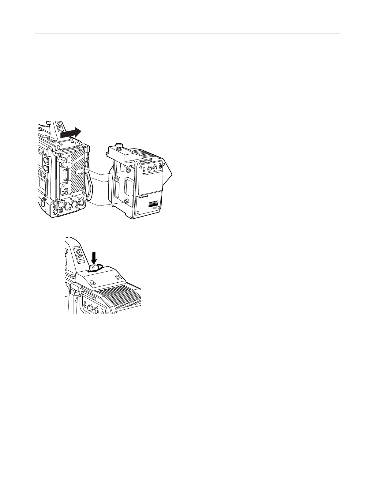
2.
As shown in the figure on the left, align the spacer on the
back of the camera recorder with the guide in the unit, and
push the unit in the direction of the arrow until it clicks into
place.
1.
Make sure that the coin screw used to secure the AJ-CA900P connectors is unscrewed (The screw will be completely
disengaged from the thread.). Mounting the AJ-CA900P with the screw in the closed position could damage the connectors.
3.
Screw the coin screw to the closed position while pressing
down on it.
Coin screw
Follow the steps below to attach the unit to the camera recorder.
<Notes>
The spacer must be mounted on the camera recorder before the unit is attached. For details on how to mount the spacer, consult
your dealer.
Depending on the version of the software being used with the camera recorder, it may be necessary to update it, in which case you
should consult your dealer.
ON
OFF
MIC
INCOM
LEVEL
O
N
O
F
PGM
P
O
N
- 4 -
RET 1 RET 2
INCOM
PUSH
PUSH
PGM OUT
CALL
RET SW
DC 12V IN
DC OUT
1
2
3
4
5
6
7
8
500mA
12V
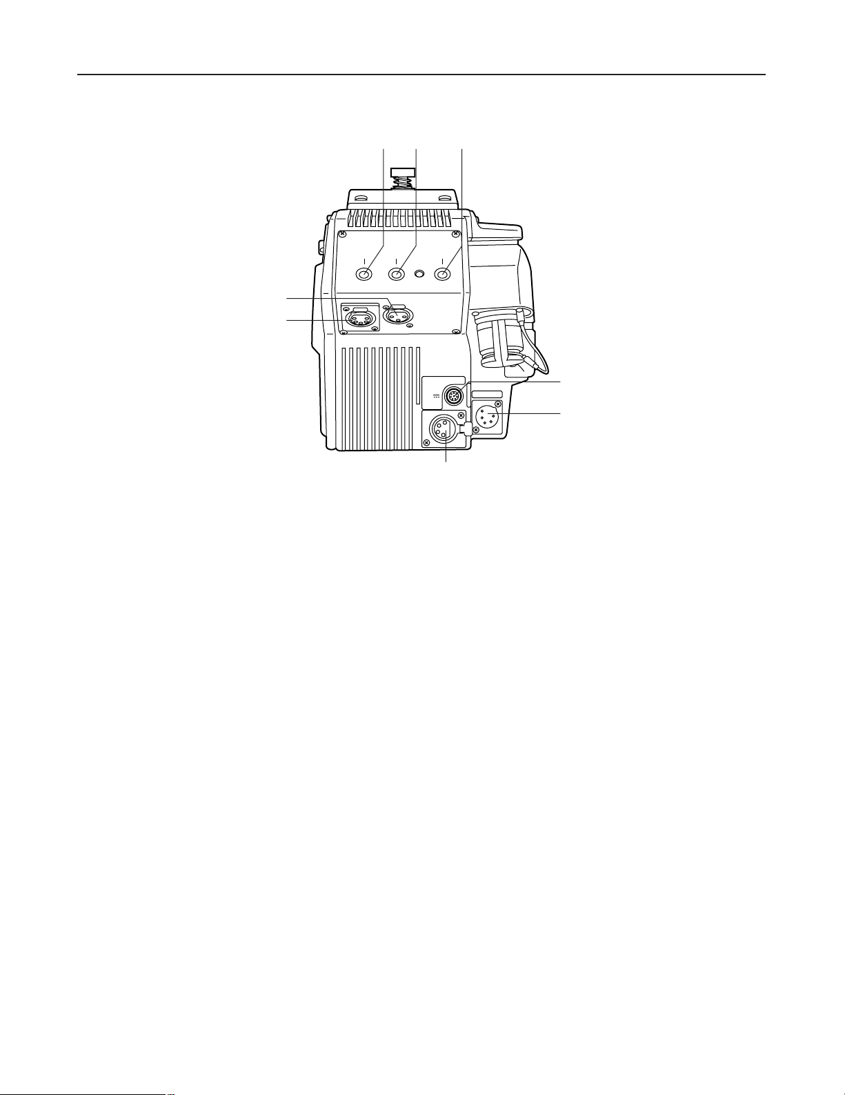
Parts and their functions
1
Return select button (RET1)
This button is used to select the return signal generated when the return switch is pressed. This button
selects RET1.
2
Return select button (RET2)
This button is used to select the return signal generated when the return switch is pressed. This button
selects RET2.
3
CALL button
This button is used to call the base station (AJ-BS900P) from the camera adapter. Pressing the CALL button
causes the CALL lamp on the AJ-BS900P to light.
4
Return switch jack (RET SW)
This jack connects to RET SW BOX. Supported functions are RET1 and RET2 selection as well as intercom
PTT (push to talk) and CALL.
Rear panel
6
DC OUT (DC power supply output) jack
This is a DC 12 V output jack. A current up to 500 mA can be output from this jack.
5
DC 12V IN (external power supply input) jack
When the unit is operated using an external power supply, the AJ-B95 AC adapter (sold separately) connects
to this jack. It is also possible to connect an external battery to this jack.
When connection is made to this jack, the external power supply is selected automatically.
7
Intercom connector
This connecter is used to connect to an intercom system via the AJ-BS900P for two-way voice connections.
8
PGM OUT connector
This is the PGM audio output connector.
- 5 -
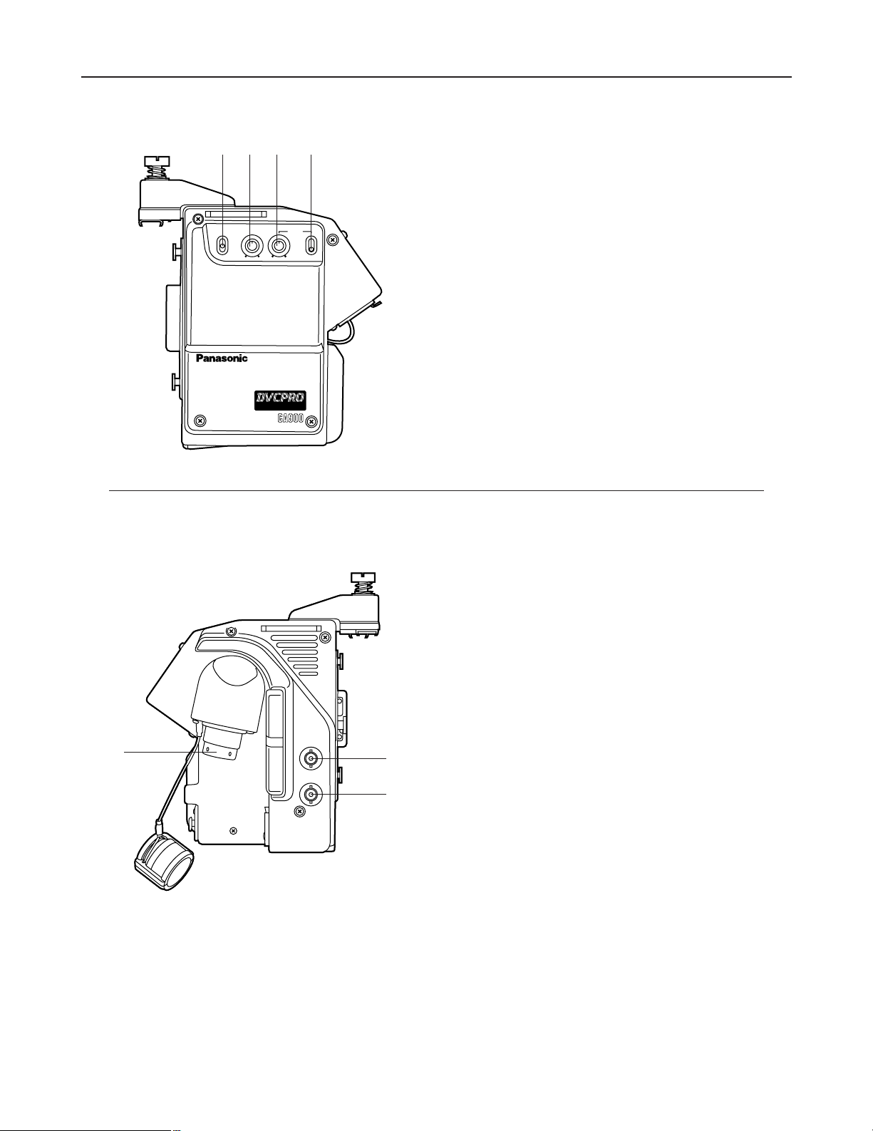
Parts and their functions
1
Microphone intercom switch (MIC)
Used to switch the intercom line between the ON, OFF,
and PTT settings. (PTT: Audio transmission continues as
long as the switch is held down.)
2
Intercom level knob (LEVEL)
This knob is used to adjust the intercom reception volume
level.
3
Program level knob (PGM)
This knob is used to adjust the intercom PGM volume level.
4
Program line switch
This switch controls the program line multiplexed on the
intercom line. It has two positions: ON and OFF.
AJ-Camera
Adapter
MIC LEVEL
INCOM
PGM
ON
OFF
ON
OFF
PTT
DIGITAL TRIAX
1
2
34
Left side
3
Triax connector
This connector is used to connect to the base station (AJBS900P) using a triax cable.
1
Prompter video output (PROMPT OUT)
The prompter video signal input to the base station (AJBS900P) is output from this jack.
2
Return video output (RET OUT)
The return video signal (either RET1 or RET2) input to the
base station (AJ-BS900P) is output from this jack.
RET-1 or RET-2 is selected by operating the return select
button (see page 4).
PROMPT
OUT
RET OUT
PROMPT
OUT
RET OUT
1
2
3
Right side
 Loading...