

Page 1
BEFORE USE
DESCRIPTION
OF PARTS
PREPARATION
SHOOTING
PLAYBACK
EDITING
DISPLAYS
MENUS
TROUBLE-
SHOOTING
SPECIFI-
CATIONS,
OTHER
Page 2
2
IMPORTANT
“Unauthorized recording of copyrighted television programs, video tapes and other materials may
infringe the right of copyright owners and be contrary to copyright laws.”
indicates safety information.
CAUTION
RISK OF ELECTRIC SHOCK
DO NOT OPEN
CAUTION: TO REDUCE THE RISK OF ELECTRIC
SHOCK, DO NOT REMOVE COVER (OR BACK).
NO USER SERVICEABLE PARTS INSIDE.
REFER TO SERVICING TO QUALIFIED SERVICE
PERSONNEL.
The lightning flash with arrowhead symbol,
within an equilateral triangle, is intended to
alert the user to the presence of uninsulated
“dangerous voltage” within the product’s
enclosure that may be of sufficient magnitude
to constitute a risk of electric shock to
persons.
The exclamation point within an equilateral
triangle is intended to alert the user to the
presence of important operating and
maintenance (service) instructions in the
literature accompanying the appliance.
CAUTION:
TO REDUCE THE RISK OF FIRE OR SHOCK
HAZARD AND ANNOYING INTERFERENCE,
USE THE RECOMMENDED ACCESSORIES
ONLY.
FCC Note:
This equipment has been tested and found to
comply with the limits for a class A digital
device, pursuant to Part 15 of the FCC Rules.
These limits are designed to provide reasonable
protection against harmful interference when the
equipment is operated in a commercial
environment. This equipment generates, uses,
and can radiate radio frequency energy and, if
not installed and used in accordance with the
instruction manual, may cause harmful
interference to radio communications. Operation
of this equipment in a residential area is likely to
cause harmful interference in which case the
user will be required to correct the interference
at his own expense.
Warning:
To assure continued FCC emission limit
compliance, the user must use only shielded
interface cable when connecting to external
units. Also, any unauthorized changes or
modifications to this equipment could void the
user’s authority to operate it.
CAUTION:
Do not install or place this unit in a
bookcase, built-in cabinet or any other
confined space in order to maintain
adequate ventilation. Ensure that curtains
and any other materials do not obstruct the
ventilation to prevent risk of electric shock
or fire hazard due to overheating.
CAUTION:
Danger of explosion or fire if battery is
mistreated.
OReplace only with same or specified type.
ODo not disassemble or dispose of in fire.
O
Do not store in temperatures over 140°F (60°C).
OUse specified charger for rechargeable
batteries.
ODo not recharge the battery if it is not a
rechargeable type.
For Remote Controller
O Replace battery with part No. CR2025 only.
O Do not recharge the battery.
WARNING:
TO REDUCE THE RISK OF FIRE OR SHOCK
HAZARD, DO NOT EXPOSE THIS
EQUIPMENT TO RAIN OR MOISTURE.
TO REDUCE THE RISK OF FIRE OR SHOCK
HAZARD, KEEP THIS EQUIPMENT AWAY
FROM ALL LIQUIDS-USE AND STORE ONLY
IN LOCATIONS WHICH ARE NOT EXPOSED
TO THE RISK OF DRIPPING OR SPLASHING
LIQUIDS, AND DO NOT PLACE ANY LIQUID
CONTAINERS ON TOP OF THE EQUIPMENT.
Notice (U.S.A.only):
This product has a fluorescent lamp that
contains a small amount of mercury.
It also contains lead in some components.
Disposal of these materials may be regulated
in your community due to environmental
considerations.
For disposal or recycling information please
contact your local authorities, or the
Electronics Industries Alliance:
<http://www.eiae.org.>
CAUTION:
TO PREVENT ELECTRIC SHOCK, MATCH
WIDE BLADE OF PLUG TO WIDE SLOT,
FULLY INSERT.
CAUTION:
THE AC OUTLET (MAINS SOCKET) SHALL
BE INSTALLED NEAR THE EQUIPMENT AND
SHALL BE EASILY ACCESSIBLE.
Camera-Recorder
OThe rating plate is on the underside of the
Camera-Recorder
AC Adapter
OThe rating plate is on the underside of the AC
Adapter.
ODisconnect the AC mains plug from the AC
mains socket when not in use.
Page 3

3
BEFORE USE
Important Safeguards
1. Read Instructions — All the safety and
operating instructions should be read before
the unit is operated.
2. Retain Instructions — The safety and
operating instructions should be retained for
future reference.
3. Heed Warnings — All warnings on the unit
and in the operating instructions should be
adhered to.
4. Follow Instructions — All operating and
maintenance instructions should be
followed.
5. Cleaning — Unplug this video unit from the
wall outlet before cleaning. Do not use liquid
or aerosol cleaners. Use a dry cloth for
cleaning.
6. Attachments — Do not use attachments not
recommended by the video product
manufacturer as they may be hazardous.
7. Water and Moisture — Do not use this video
unit near water — for example near a bath
tub, wash bowl, kitchen sink, or laundry tub,
in a wet basement, or near a swimming pool,
and the like.
8. Accessories — Do not place this video unit
on an unstable cart, stand, tripod, bracket, or
table. The video unit may fall, causing
serious injury to a child or adult, and serious
damage to the unit. Use only with a cart,
stand, tripod, bracket, or table
recommended by the manufacturer, or sold
with the video unit. Any mounting of the unit
should follow the manufacturer’s instructions
and should use a mounting accessory
recommended by the manufacturer.
An appliance and cart
combination should be
moved with care. Quick
stops, excessive force,
and uneven surfaces
may cause the appliance
and cart combination to
overturn.
9. Ventilation — Slots and openings in the
cabinet are provided for ventilation and to
ensure reliable operation of the video unit
and to protect it from overheating. These
openings must not be blocked or covered.
Never place the video unit on a bed, sofa,
rug, or other similar surface, or near or over
a radiator or heat register. This video unit
should not be placed in a built-in installation
such as a bookcase or rack unless proper
ventilation is provided or the manufacturer's
instructions have been adhered to.
10. Power Sources — This video unit should be
operated only from the type of power source
indicated on the marking label. If you are not
sure of the type of power supply to your
home, consult your appliance dealer or local
power company. For video units intended to
be operated from battery power, or other
sources, refer to the operating instructions.
11. Grounding or Polarization — This video unit
may be equipped with either a polarized 2wire AC (Alternating Current) line plug (a
plug having one blade wider than the other)
or 3-wire grounding type plug, a plug having
a third (grounding) pin.
The 2-wire polarized plug will fit into the
power outlet only one way. This is a safety
feature. If you are unable to insert the plug
fully into the outlet, try reversing the plug. If
the plug still fails to fit, contact your
electrician to replace your obsolete outlet.
Do not defeat the safety purpose of the
polarized plug.
The 3-wire grounding type plug will fit into a
grounding type power outlet. This is a safety
feature. If you are unable to insert the plug
into the outlet, contact your electrician to
replace your obsolete outlet. Do not defeat
the safety purpose of the grounding type
plug.
12. Power-Cord Protection — Power-supply
cords should be routed so that they are not
likely to be walked on or pinched by items
placed upon or against them, paying
particular attention to cords of plugs,
convenience receptacles, and the point
where they exit from the unit.
Page 4
4
Important Safeguards
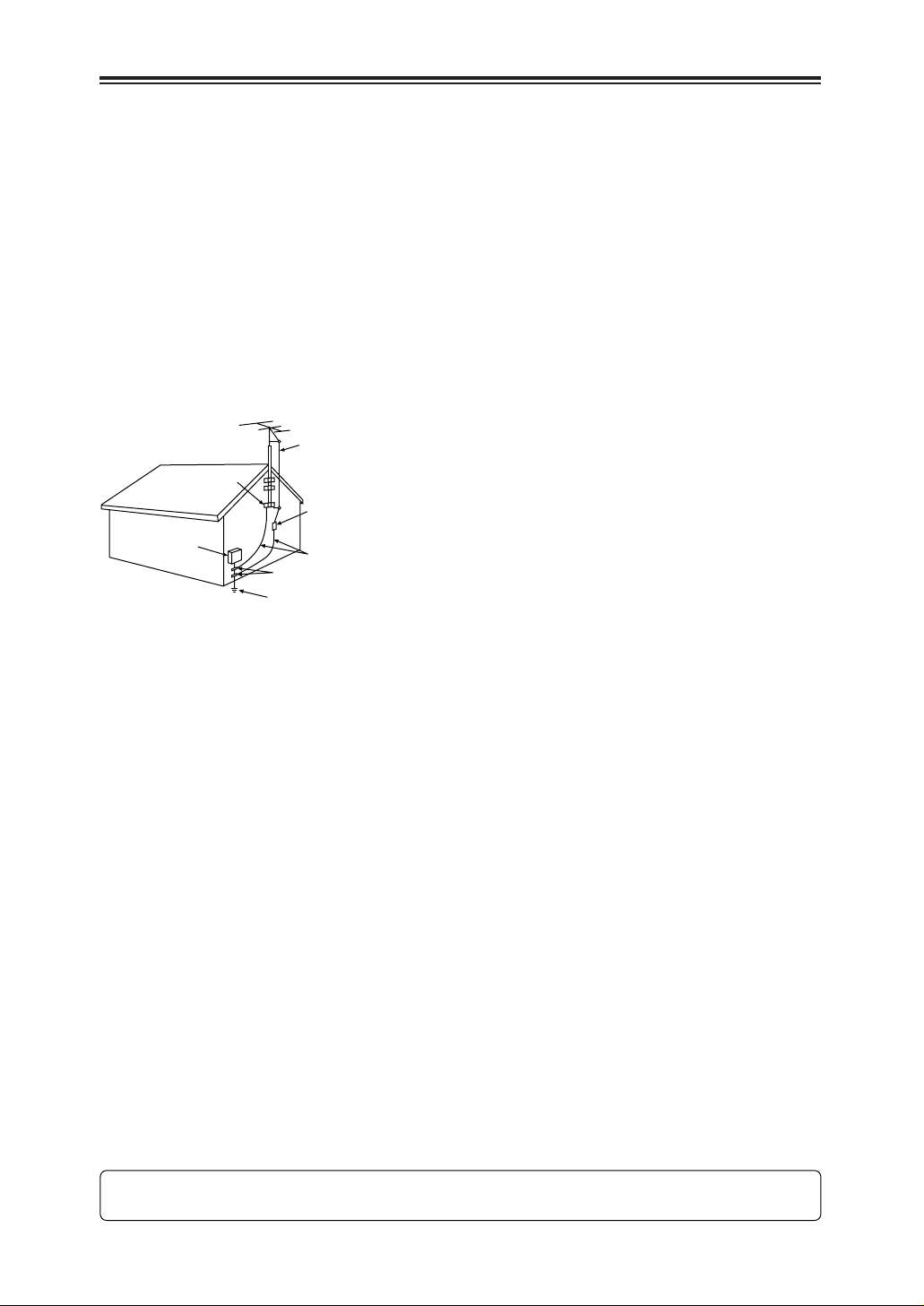
13. Outdoor Antenna Grounding — If an outside
antenna or cable system is connected to the
video unit, be sure the antenna or cable
system is grounded so as to provide some
protection against voltage surges and builtup static charges. Part 1 of the Canadian
Electrical Code, in USA Section 810 of the
National Electrical Code, provides
information with respect to proper grounding
of the mast and supporting structure,
grounding of the lead-in wire to an antenna
discharge unit, size of grounding conductors,
location of antenna discharge unit,
connection to grounding electrodes, and
requirements for the grounding electrode.
14. Lightning — For added protection of this
video unit receiver during a lightning storm,
or when it is left unattended and unused for
long periods of time, unplug it from the wall
outlet and disconnect the antenna or cable
system. This will prevent damage to the
video unit due to lightning and power-line
surges.
15. Power Lines — An outside antenna system
should not be located in the vicinity of
overhead power lines or other electric light
or power circuits, or where it can fall into
such power lines or circuits. When installing
an outside antenna system, extreme care
should be taken to keep from touching such
power lines or circuits as contact with them
might be fatal.
16. Overloading — Do not overload wall outlets
and extension cords as this can result in a
risk of fire or electric shock.
17. Objects and Liquids — Never push objects
of any kind into this video unit through
openings as they may touch dangerous
voltage points or short out parts that could
result in a fire or electric shock. Never spill
liquid of any kind onto the video unit.
18. Servicing — Do not attempt to service this
video unit yourself as opening or removing
covers may expose you to dangerous
voltage or other hazards. Refer all servicing
to qualified service personnel.
19. Damage Requiring Service — Unplug this
video unit from the wall outlet and refer
servicing to qualified service personnel
under the following conditions:
a. When the power-supply cord or plug is
damaged.
b. If any liquid has been spilled onto, or
objects have fallen into the video unit.
c. If the video unit has been exposed to rain
or water.
d. If the video unit does not operate normally
by following the operating instructions.
Adjust only those controls that are
covered by the operating instructions, as
an improper adjustment of other controls
may result in damage and will often
require extensive work by a qualified
technician to restore the video unit to its
normal peration.
e. If the video unit has been dropped or the
cabinet has been damaged.
f. When the video unit exhibits a distinct
change in performance – this indicates a
need for service.
20. Replacement Parts — When replacement
parts are required, be sure the service
technician has used replacement parts
specified by the manufacturer or have the
same characteristics as the original part.
Unauthorized substitutions may result in fire,
electric shock or other hazards.
21. Safety Check — Upon completion of any
service or repairs to this video unit, ask the
service technician to perform safety checks
to determine that the video unit is in safe
operating order.
FCC Warning: Any unauthorized changes or modifications to this equipment would void the
user’s authority to operate.
ANTENNA LEAD IN WIRE
GROUND
CLAMP
ELECTRIC
SERVICE
EQUIPMENT
NEC – NATIONAL
ELECTRICAL CODE
ANTENNA DISCHARGE UNIT
(NEC SECTION 810-20)
GROUNDING CONDUCTORS
(NEC SECTION 810-21)
GROUND CLAMPS
POWER SERVICE GROUNDING
ELECTRODE SYSTEM
(NEC ART 250, PART H)
Page 5

5
BEFORE USE
Read this first!
Always take some trial shots before actual
shooting.
When shooting important events (such as
weddings), always take some trial shots and
check that the sound and images have been
recorded properly before actual shooting.
Remember to check the settings especially
when you intend to use special effects or
backlight compensation.
Panasonic makes no guarantees for your
recordings.
Please understand that Panasonic makes no
guarantees for your recordings in cases where
images and/or sound were not recorded as you
intended due to problems with the camerarecorder or cassette.
Respect copyrights
Copyright laws forbid the use of video and audio
material you have recorded for any purpose
other than your own personal enjoyment.
Remember that restrictions apply to the
shooting of certain material even it is intended
for private use.
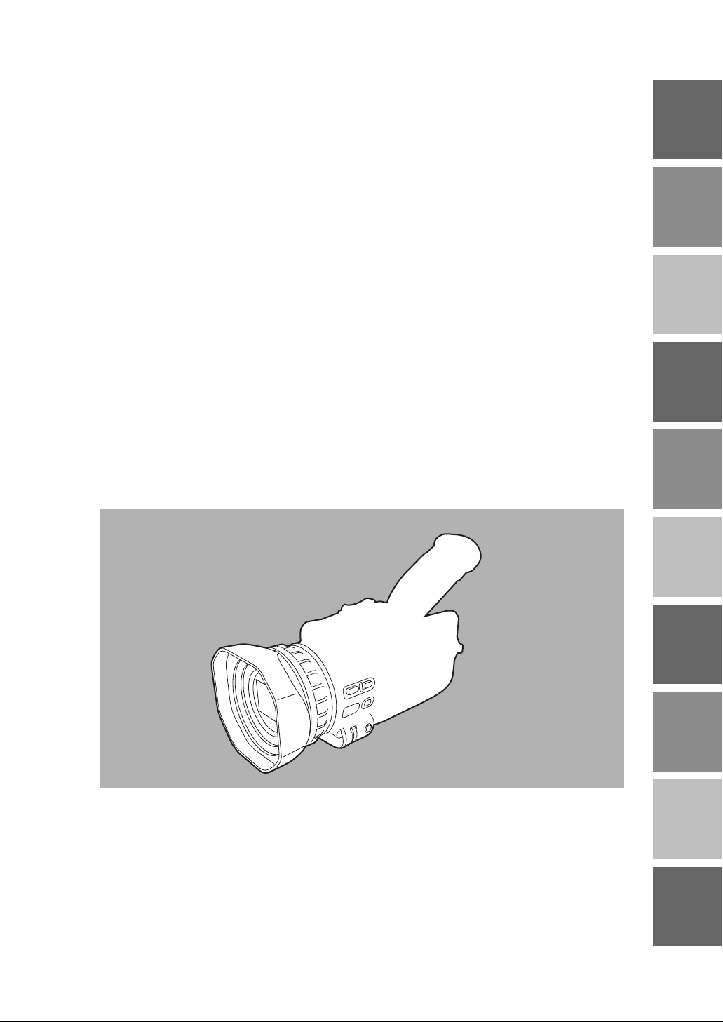
Caution concerning illustrations in these
instructions
O Note that all illustrations (camera-recorder,
menu screens, etc.) in these operating
instructions will differ slightly from the actual
camera-recorder.
O If the operations described can be performed
using either the camera-recorder or the
remote control unit, an illustration of the
remote control unit is shown alongside.
Reference pages
Reference pages are indicated as (P00).
Usable cassette tapes
Digital video cassette tapes with the Ò mark
can be used with this camera-recorder.
Page 6

6
Contents
Accessories . . . . . . . . . . . . . . . . . . . . . . . . . . . . . . .8
Operating precautions . . . . . . . . . . . . . . . . . . . . . . .9
Storage precautions . . . . . . . . . . . . . . . . . . . . . . .11
Checking the system operations . . . . . . . . . . . . .12
Getting ready . . . . . . . . . . . . . . . . . . . . . . . . . . . .12
Connecting the power cord . . . . . . . . . . . . . . . . .12
Inserting the cassette tape . . . . . . . . . . . . . . . . . .13
Turning on the power . . . . . . . . . . . . . . . . . . . . . .13
Shooting . . . . . . . . . . . . . . . . . . . . . . . . . . . . . . . .14
Checking what you have shot (rec check) . . . . . .14
Removing the tape . . . . . . . . . . . . . . . . . . . . . . . .15
Turning off the power . . . . . . . . . . . . . . . . . . . . . .15
Disconnecting the power cord . . . . . . . . . . . . . . .15
Adjusting the hand strap . . . . . . . . . . . . . . . . . . . .16
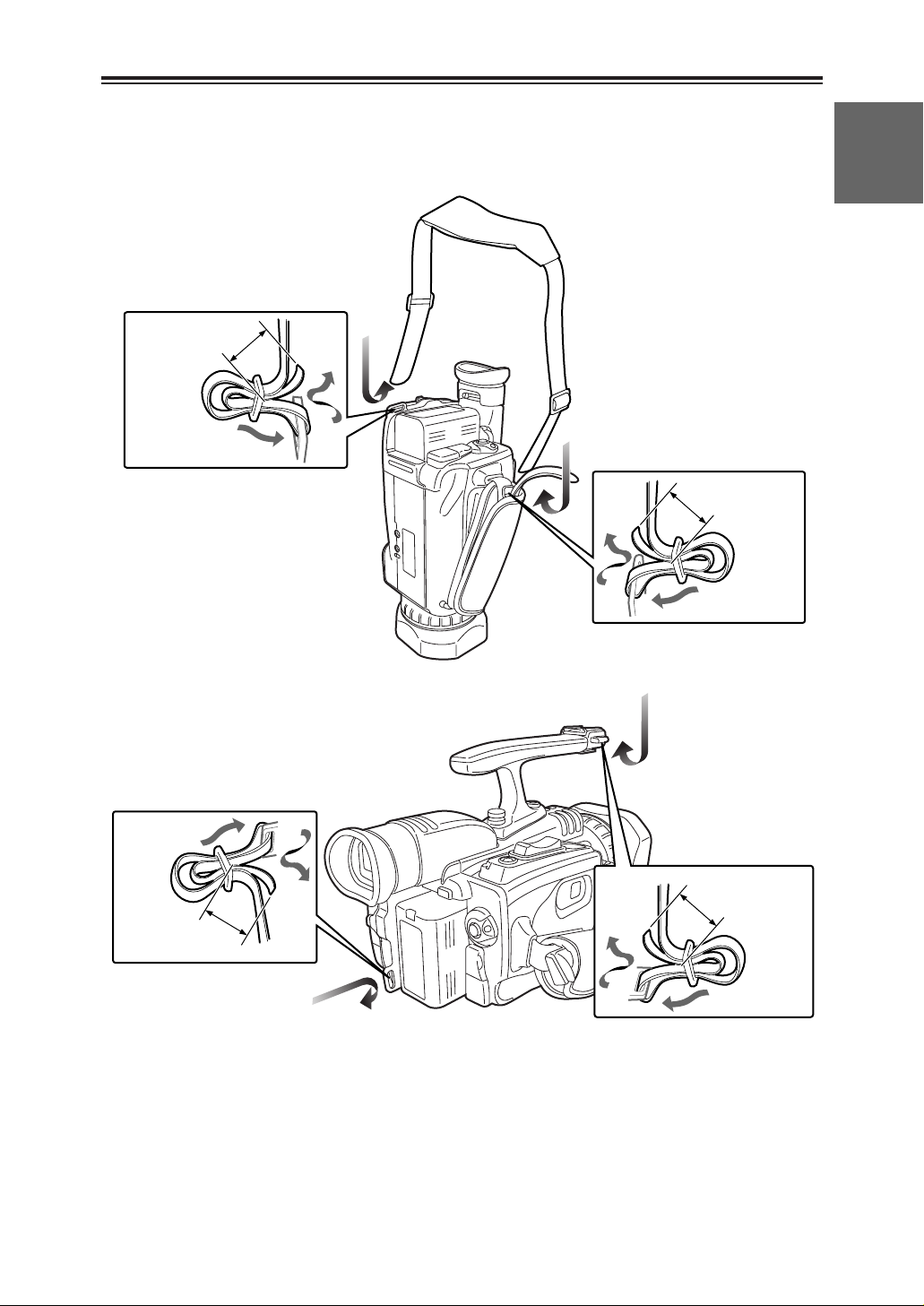
Attaching the handle . . . . . . . . . . . . . . . . . . . . . . .16
Attaching the large eye-cup . . . . . . . . . . . . . . . . .16
Attaching the shoulder strap . . . . . . . . . . . . . . . .17
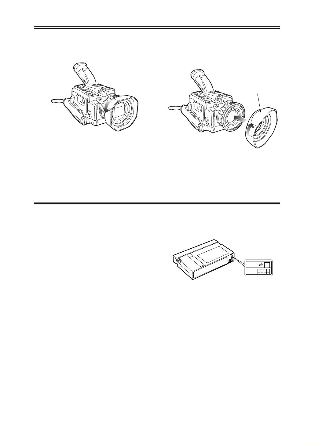
Lens hood . . . . . . . . . . . . . . . . . . . . . . . . . . . . . . . .18
Cassette tapes . . . . . . . . . . . . . . . . . . . . . . . . . . . .18
BEFORE USE
Camera-recorder . . . . . . . . . . . . . . . . . . . . . . . . . .19
Wireless remote control unit . . . . . . . . . . . . . . . . .22
DESCRIPTION OF PARTS
Battery . . . . . . . . . . . . . . . . . . . . . . . . . . . . . . . . . . .23
Charging . . . . . . . . . . . . . . . . . . . . . . . . . . . . . . .23
Mounting . . . . . . . . . . . . . . . . . . . . . . . . . . . . . . .24
Removing . . . . . . . . . . . . . . . . . . . . . . . . . . . . . . .24
Remote control unit . . . . . . . . . . . . . . . . . . . . . . . .25
Installing the battery . . . . . . . . . . . . . . . . . . . . . . .25
Setting the remote control unit . . . . . . . . . . . . . . .25
Viewfinder . . . . . . . . . . . . . . . . . . . . . . . . . . . . . . . .26
Using the viewfinder . . . . . . . . . . . . . . . . . . . . . .26
Using the LCD monitor . . . . . . . . . . . . . . . . . . . .26
Adjusting the screen display . . . . . . . . . . . . . . . .27
Time data . . . . . . . . . . . . . . . . . . . . . . . . . . . . . . . .29
Adjusting the calendar . . . . . . . . . . . . . . . . . . . . .29
Charging the internal battery . . . . . . . . . . . . . . . .30
Setting the user’s bit . . . . . . . . . . . . . . . . . . . . . .31
Setting the time code . . . . . . . . . . . . . . . . . . . . . .33
Specifying the time code . . . . . . . . . . . . . . . . . . .33
PREPARATION
Regular shooting . . . . . . . . . . . . . . . . . . . . . . . . . .35
Preparation and inspections . . . . . . . . . . . . . . . .35
Shooting . . . . . . . . . . . . . . . . . . . . . . . . . . . . . . . .35
Shooting techniques for different targets . . . . . .36
Low-angle shooting . . . . . . . . . . . . . . . . . . . . . . .36
Searching specific scenes (image search) . . . . .36
Zoom functions . . . . . . . . . . . . . . . . . . . . . . . . . .36
Self-portrait shooting . . . . . . . . . . . . . . . . . . . . . .37
Recording the time stamp . . . . . . . . . . . . . . . . . .37
High-sensitivity shooting (SNS) . . . . . . . . . . . . . .37
Vibration reduction function . . . . . . . . . . . . . . . . .38
Wind noise reduction . . . . . . . . . . . . . . . . . . . . . .38
Movie-like shooting . . . . . . . . . . . . . . . . . . . . . . .38
Photo shots . . . . . . . . . . . . . . . . . . . . . . . . . . . . .39
Color bars . . . . . . . . . . . . . . . . . . . . . . . . . . . . . .39
Zebra pattern . . . . . . . . . . . . . . . . . . . . . . . . . . . .39
Markers . . . . . . . . . . . . . . . . . . . . . . . . . . . . . . . .39
Field and frame shooting . . . . . . . . . . . . . . . . . . .40
Frame-by-frame shooting . . . . . . . . . . . . . . . . . .40
Changing the image size . . . . . . . . . . . . . . . . . . .40
Using the USER buttons . . . . . . . . . . . . . . . . . . .41
One-touch zooming . . . . . . . . . . . . . . . . . . . . . . .41
Backlight compensation function . . . . . . . . . . . . .41
AE lock function . . . . . . . . . . . . . . . . . . . . . . . . . .41
Index recording . . . . . . . . . . . . . . . . . . . . . . . . . .41
Backup recording . . . . . . . . . . . . . . . . . . . . . . . . .42
Switching to manual mode . . . . . . . . . . . . . . . . . .42
Focusing . . . . . . . . . . . . . . . . . . . . . . . . . . . . . . .42
Shutter speed, iris and gain adjustments . . . . . .43
Shutter speed adjustment . . . . . . . . . . . . . . . . . .43
Iris and gain adjustments . . . . . . . . . . . . . . . . . . .44
White balance adjustments . . . . . . . . . . . . . . . . . .45
Auto white balance . . . . . . . . . . . . . . . . . . . . . . .45
Setting the white balance . . . . . . . . . . . . . . . . . . .45
Adjusting the white balance manually . . . . . . . . .46
Audio level adjustments . . . . . . . . . . . . . . . . . . . .47
Adjusting the mic input audio level . . . . . . . . . . .47
Adjusting the headphone volume . . . . . . . . . . . .48
SHOOTING
Page 7

7
BEFORE USE
O “LEICA” is a registered trademark of Leica Microsystems IR GmbH.
O “DICOMAR” is a registered trademark of Leica Camera AG.
Other names, company names or product names mentioned in these instructions are the
trademarks or registered trademarks of the companies concerned.
Normal playback . . . . . . . . . . . . . . . . . . . . . . . . . .49
Playing back a tape . . . . . . . . . . . . . . . . . . . . . . .49
Adjusting the volume . . . . . . . . . . . . . . . . . . . . . .50
Connecting a TV to view images . . . . . . . . . . . . .50
Checking the shooting date and time . . . . . . . . .50
Variable-speed playback . . . . . . . . . . . . . . . . . . . .51
Slow playback . . . . . . . . . . . . . . . . . . . . . . . . . . .51
Still-picture playback . . . . . . . . . . . . . . . . . . . . . .51
Frame-feed playback . . . . . . . . . . . . . . . . . . . . . .51
Cue and review . . . . . . . . . . . . . . . . . . . . . . . . . .51
Search functions . . . . . . . . . . . . . . . . . . . . . . . . . .52
Variable-speed search . . . . . . . . . . . . . . . . . . . . .52
Blank search . . . . . . . . . . . . . . . . . . . . . . . . . . . .52
Index search . . . . . . . . . . . . . . . . . . . . . . . . . . . .53
Counter . . . . . . . . . . . . . . . . . . . . . . . . . . . . . . . . . .54
Counter display . . . . . . . . . . . . . . . . . . . . . . . . . .54
Counter memory function . . . . . . . . . . . . . . . . . .54
PLAYBACK
Connecting external units . . . . . . . . . . . . . . . . . . .55
Headphones . . . . . . . . . . . . . . . . . . . . . . . . . . . .55
Digital video equipment . . . . . . . . . . . . . . . . . . . .55
TV set . . . . . . . . . . . . . . . . . . . . . . . . . . . . . . . . .56
Video deck . . . . . . . . . . . . . . . . . . . . . . . . . . . . . .56
External microphone
(connected to phono jack) . . . . . . . . . . . . . . .57
External microphone
(connected to XLR connector) . . . . . . . . . . . .57
Audio dubbing . . . . . . . . . . . . . . . . . . . . . . . . . . . .58
Dubbing . . . . . . . . . . . . . . . . . . . . . . . . . . . . . . . . . .60
Analog input . . . . . . . . . . . . . . . . . . . . . . . . . . . . .60
Analog output . . . . . . . . . . . . . . . . . . . . . . . . . . . .61
Digital input/output . . . . . . . . . . . . . . . . . . . . . . . .62
EDITING
Screen displays . . . . . . . . . . . . . . . . . . . . . . . . . . .63
Displays in CAMERA and VCR modes . . . . . . . .63
In VCR mode only . . . . . . . . . . . . . . . . . . . . . . . .66
Warnings . . . . . . . . . . . . . . . . . . . . . . . . . . . . . . .66
Using the MODE CHK button . . . . . . . . . . . . . . .67
Setting the DISPLAY items . . . . . . . . . . . . . . . . .67
DISPLAYS
Menu operations . . . . . . . . . . . . . . . . . . . . . . . . . .68
Setting the menu mode . . . . . . . . . . . . . . . . . . . .68
Selecting the main items . . . . . . . . . . . . . . . . . . .69
Selecting the sub items . . . . . . . . . . . . . . . . . . . .69
Entering the settings . . . . . . . . . . . . . . . . . . . . . .70
Setting other sub items . . . . . . . . . . . . . . . . . . . .71
Returning to the main item screen . . . . . . . . . . . .71
Setting other main items . . . . . . . . . . . . . . . . . . .71
Releasing the menu mode . . . . . . . . . . . . . . . . . .71
Initializing the menu settings . . . . . . . . . . . . . . . .71
Menu configuration . . . . . . . . . . . . . . . . . . . . . . . .72
CAMERA mode menu . . . . . . . . . . . . . . . . . . . . .72
VCR mode menu . . . . . . . . . . . . . . . . . . . . . . . . .72
SCENE FILE screen . . . . . . . . . . . . . . . . . . . . . .73
CAMERA SETUP screen . . . . . . . . . . . . . . . . . . .73
PLAYBACK FUNCTION screen . . . . . . . . . . . . .74
SW MODE screen . . . . . . . . . . . . . . . . . . . . . . . .75
RECORDING SETUP screen . . . . . . . . . . . . . . .76
AV IN/OUT SETUP screen . . . . . . . . . . . . . . . . .78
DISPLAY SETUP screen . . . . . . . . . . . . . . . . . . .78
OTHER FUNCTIONS screen . . . . . . . . . . . . . . .79
MENUS
Before calling for service . . . . . . . . . . . . . . . . . . .81
Power supply . . . . . . . . . . . . . . . . . . . . . . . . . . . .81
Battery . . . . . . . . . . . . . . . . . . . . . . . . . . . . . . . . .81
Normal video recording . . . . . . . . . . . . . . . . . . . .81
Other types of video recording . . . . . . . . . . . . . . .82
Editing . . . . . . . . . . . . . . . . . . . . . . . . . . . . . . . . .82
Displays . . . . . . . . . . . . . . . . . . . . . . . . . . . . . . . .82
Playback (images) . . . . . . . . . . . . . . . . . . . . . . . .82
Playback (sound) . . . . . . . . . . . . . . . . . . . . . . . . .83
Other . . . . . . . . . . . . . . . . . . . . . . . . . . . . . . . . . .83
TROUBLESHOOTING
Condensation . . . . . . . . . . . . . . . . . . . . . . . . . . . . .84
Tally lamp . . . . . . . . . . . . . . . . . . . . . . . . . . . . . . . .84
System resetting . . . . . . . . . . . . . . . . . . . . . . . . . .84
Cleaning the video heads . . . . . . . . . . . . . . . . . . .85
Maintenance cautions . . . . . . . . . . . . . . . . . . . . . .85
Specifications . . . . . . . . . . . . . . . . . . . . . . . . . . . . .86
SPECIFICATIONS, OTHER
Contents (cont.)
Page 8
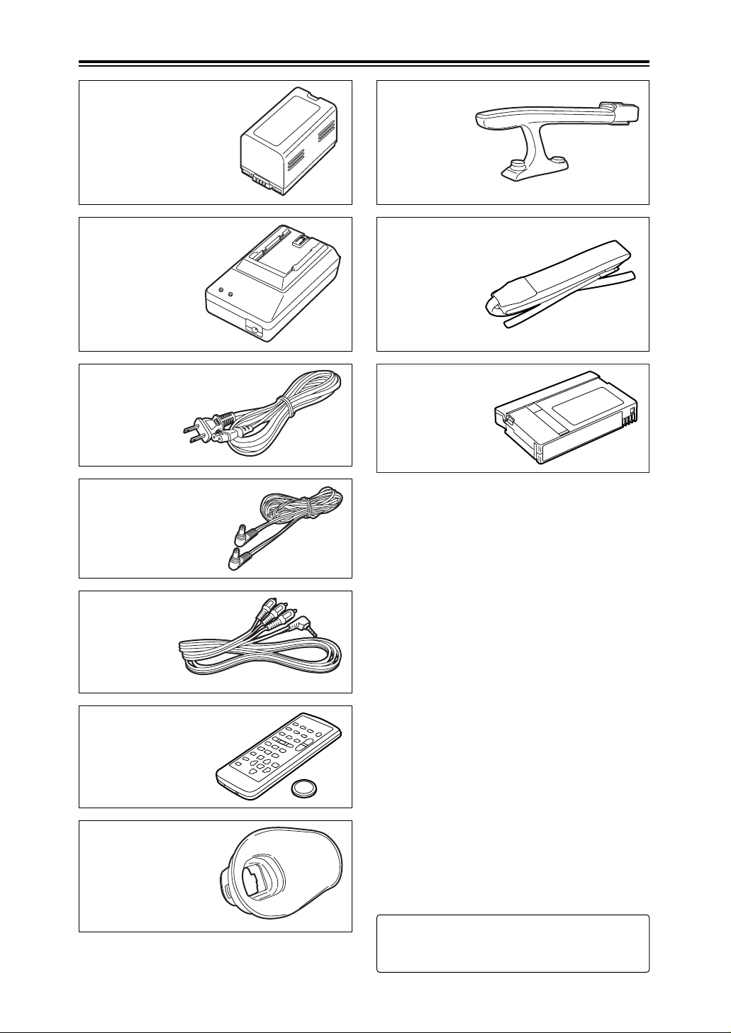
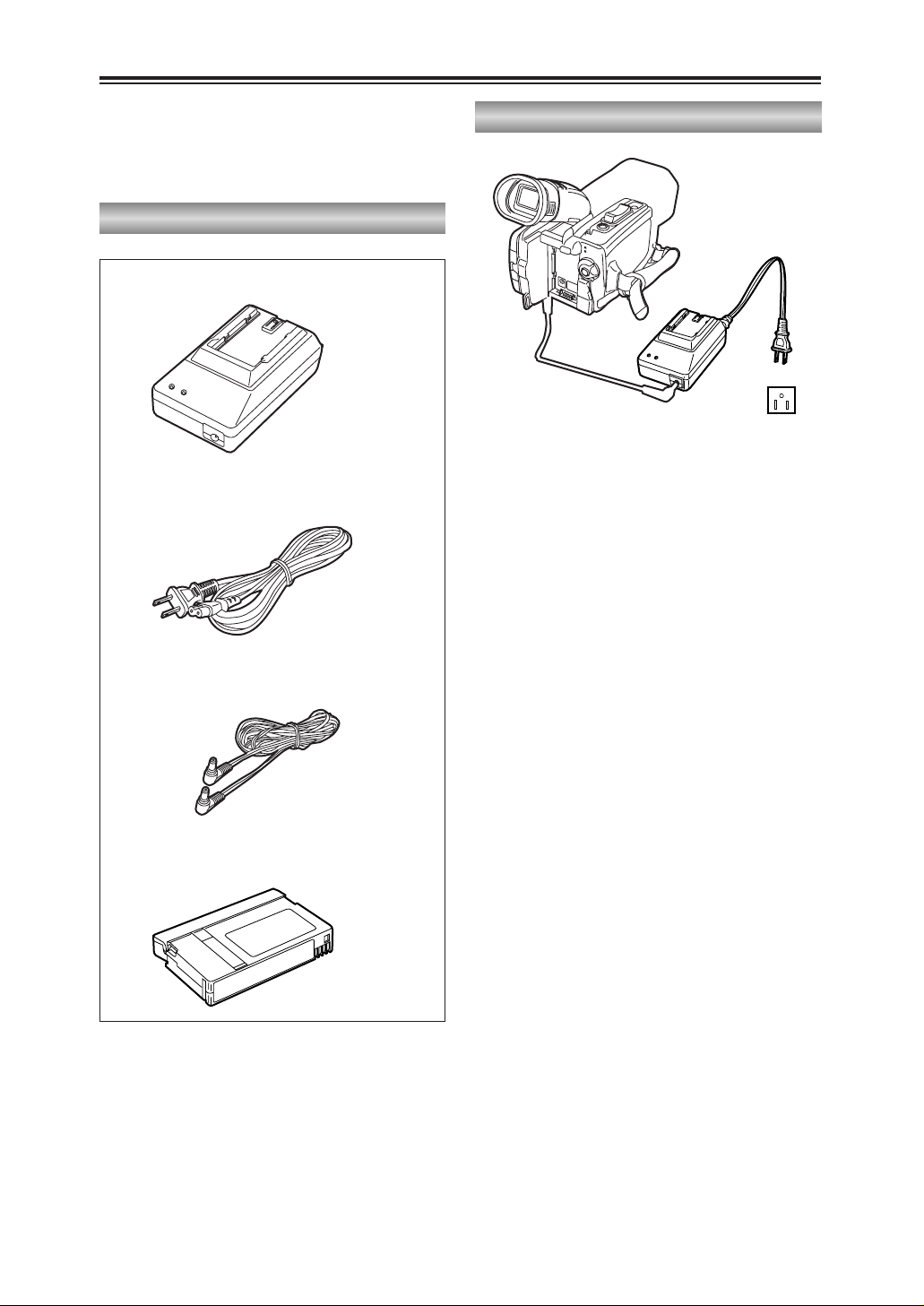
Mini DV cassette tape
(AY-DVM63MQ)
8
Accessories
Wireless remote control
(VFA0402)
Button battery
(CR2025)
DC cord
(K2GJ2DC00002)
AC cord
(K2CB2CB00006)
AV cable
(K2KC4CB00009)
Handle
(VYH0312)
Shoulder strap
(VFC3891)
Eye-cup (large)
(VMG1370)
2: For the battery and AC adapter model
numbers, refer to the “Optional peripheral
units” section. (P87)
Battery (2)
AC adapter (2)
Page 9

9
BEFORE USE
Operating precautions
Do not allow any water to get into the
camera-recorder when using it in the rain or
snow or at the beach.
O Failure to heed this caution will cause the
camera-recorder or cassette to malfunction
(and may result in irreparable damage).
Keep the camera-recorder away from
equipment (such as TV sets and video game
machines) that generate magnetic fields.
O Using the camera-recorder on top of or near
a TV set may cause distortion in the images
and/or sound due to the electromagnetic
waves that the set emits.
O The powerful magnetic fields generated by
speakers or large motors may damage your
tape recordings or distort the images.
O The electromagnetic waves emitted from a
microcomputer will adversely affect the
camera-recorder, causing the images and/or
sound to be distorted.
O If the camera-recorder is so adversely
affected by products that generate magnetic
fields that it no longer operates properly, turn
it off and remove the battery or unplug the
AC adapter from the power outlet. Then
install the battery again or re-connect the AC
adapter. After this, turn the camera-recorder
back on.
Do not use the camera-recorder near radio
transmitters or high-voltage equipment.
O Using the camera-recorder near a radio
transmitter or high-voltage equipment may
adversely affect the recorded images and/or
sound.
Do not allow any sand or dust to get into the
camera-recorder when using it at the beach
and other similar places.
O Sand and dust can damage the camera-
recorder and cassette. (Be especially careful
when inserting or removing the cassettes.)
AC adapter and battery
O If the battery has become extremely hot or
cold or if it has not been used for a long time
and has no charge, the CHARGE lamp will
blink several times and charging will start
automatically.
O If the CHARGE lamp continues to blink even
when the battery temperature is normal, it
may mean that something is wrong with the
battery or AC adapter. Consult your dealer.
O When the battery is warm, it will take longer
to charge than normal.
O When the AC adapter is used near a radio,
the sound from the radio may be distorted.
Keep the AC adapter at least a yard away
from the radio.
O Noise may be heard while the AC adapter is
being used; however, this is not a sign of
malfunctioning.
Do not drop the camera-recorder while
carrying it.
O Strong impact may damage the camera-
recorder to the extent that it will no longer
operate properly.
O When carrying the camera-recorder around,
use the hand strap, handle or shoulder strap,
and remember to handle it carefully.
Do not expose the camera-recorder to insect
sprays or volatile substances.
O Contact with insect sprays or volatile
substances may distort the shape of the
camera-recorder and/or cause its finish to
peel off.
O Do not leave the camera-recorder in contact
with rubber or PVC products for extended
periods of time.
After use, always remove the cassette and
remove the battery or unplug the AC cord
from the power outlet.
O If the cassette is left inside the camera-
recorder, the tape may become slack or
damaged.
O Leaving the battery on the camera-recorder
for an extended period may cause the battery
voltage to drop excessively, and it may not
be possible to re-use it even after charging it.
Page 10

Mounting the camera-recorder on a tripod
The depth of the tripod mounting hole is
5.5 mm.
When mounting this camera-recorder on a
tripod, do not force the screw beyond this
depth.
Note that if you use any screw other than
a 1/4-20UNC type you could damage the
camera-recorder.
Camera mounted on a tripod
(1/4-20UNC type of screw)
10
Operating precautions (cont.)
Battery characteristics
This camera-recorder uses a rechargeable
lithium-ion battery that uses its internal chemical
reaction to generate electrical energy. This
reaction is easily influenced by the ambient
temperature and humidity, and the battery’s
effective operating time is reduced as the
temperature rises or falls. When the battery is
used in an environment where the temperature
is very low, it will not allow more than 5 minutes
of operation.
If you let the battery get very hot, its protection
function will be triggered, which will make it
unusable for some time.
Always remove the battery after use.
If it is left inside, a small amount of current will
be consumed even while the camera-recorder’s
power is off. Also, if it is left inside for an
extended period, the battery may become overdischarged and it may not be possible to re-use
it even after charging it.
To dispose of an unusable battery
O The battery has a definite service life.
In order to protect valuable natural
resources, do not throw away a battery
which you no longer need. Take it to a
store that participates in the recycling of
rechargeable batteries.
Protect the battery’s terminal area.
Keep the battery’s terminal area free of dust and
other foreign matter. If a battery has been
dropped, check whether its body or terminal
area has been bent out of shape.
Attempting to install an out-of-shape battery in
the camera-recorder or mounting it in the AC
adapter may damage the camera-recorder or
AC adapter.
Liquid crystal displays
O If the same image or characters are left
displayed on the LCD monitor or viewfinder
for an extended period, they may become
burned onto the screen. However, if the
power is kept off for several hours, the
screen will return to normal.
O The liquid crystal parts are manufactured
using high-precision technology. More than
99.99% of the pixels are effective, which
means that less than 0.01% of the pixels are
missing or permanently lighted. Missing or
lighted pixels are not a sign of malfunctioning
and have no effect at all on the images which
are recorded.
O
Page 11

11
BEFORE USE
Storage precautions
Before storing the camera-recorder, remove
both the cassette and battery. Store all of these
items in a place with a low humidity and
relatively constant temperature.
Recommended temperature range:
59°F to 77°F (15°C to 25°C)
Recommended relative humidity:
40% to 60%
Camera-recorder
Wrap the camera-recorder in a soft cloth to
keep the dust off.
Battery
O The battery life is shortened in places which
are very hot or cold.
O Storing the battery in a location with oily
vapors or high dust concentrations may
corrode the terminals, cause other damage
and lead to malfunctioning.
O Keep metal objects (such as necklaces
and hairpins) away from the battery.
Short-circuiting may occur across the
terminals, causing the battery to heat up,
and you may seriously burn yourself if
you touch the battery in this state.
O The battery should be discharged for
storage. When storing it for an extended
time, we recommended that at least once a
year you charge it, use up its charge by
operating the camera-recorder, and then
store it again.
Cassette tapes
O Always rewind your tapes to the start before
storing them. If a cassette that has been
stopped part the way through is left standing
for six months or more (this timeframe differs
depending on the storage conditions), the
tape will become slack.
O Always put tapes back into their original
cases before storing them as factors such as
dust, direct sunlight (ultraviolet rays) and
humidity may damage the tapes. Dust
contains particles of hard minerals which
may damage the camera-recorder’s heads
and other parts if they get inside the
cassette.
O Fast forward and rewind your tapes once
every six months. If tapes are kept wound up
for more than a year, the expansion and
contraction caused by changes in the
temperature and humidity may distort the
tapes. Also, parts of the tape may get stuck
together.
O Do not place cassettes near equipment or
anything else with strong magnetic fields.
O The top surface of tapes is coated with
microscopically small magnetic particles
where the signals are recorded. Magnetic
necklaces, toys and other products may have
a stronger magnetic field than you might
suspect: they may be strong enough to erase
recordings and generate noise on the screen
and in the sound.
Page 12
12
Checking the system operations
Connecting the power cord
Getting ready
1
Connect the DC cord to the DC input socket.
After purchasing your camera-recorder, follow
the instructions for checking the system
operations to ensure that the unit is working
properly before you attempt to shoot anything.
2
Connect the other end of the DC cord and
one end of the AC cord to the AC adapter.
3
Plug the other end of the AC cord into the
power outlet.
2
2
3
Page 13
13
BEFORE USE
Checking the system operations (cont.)
Turning on the power
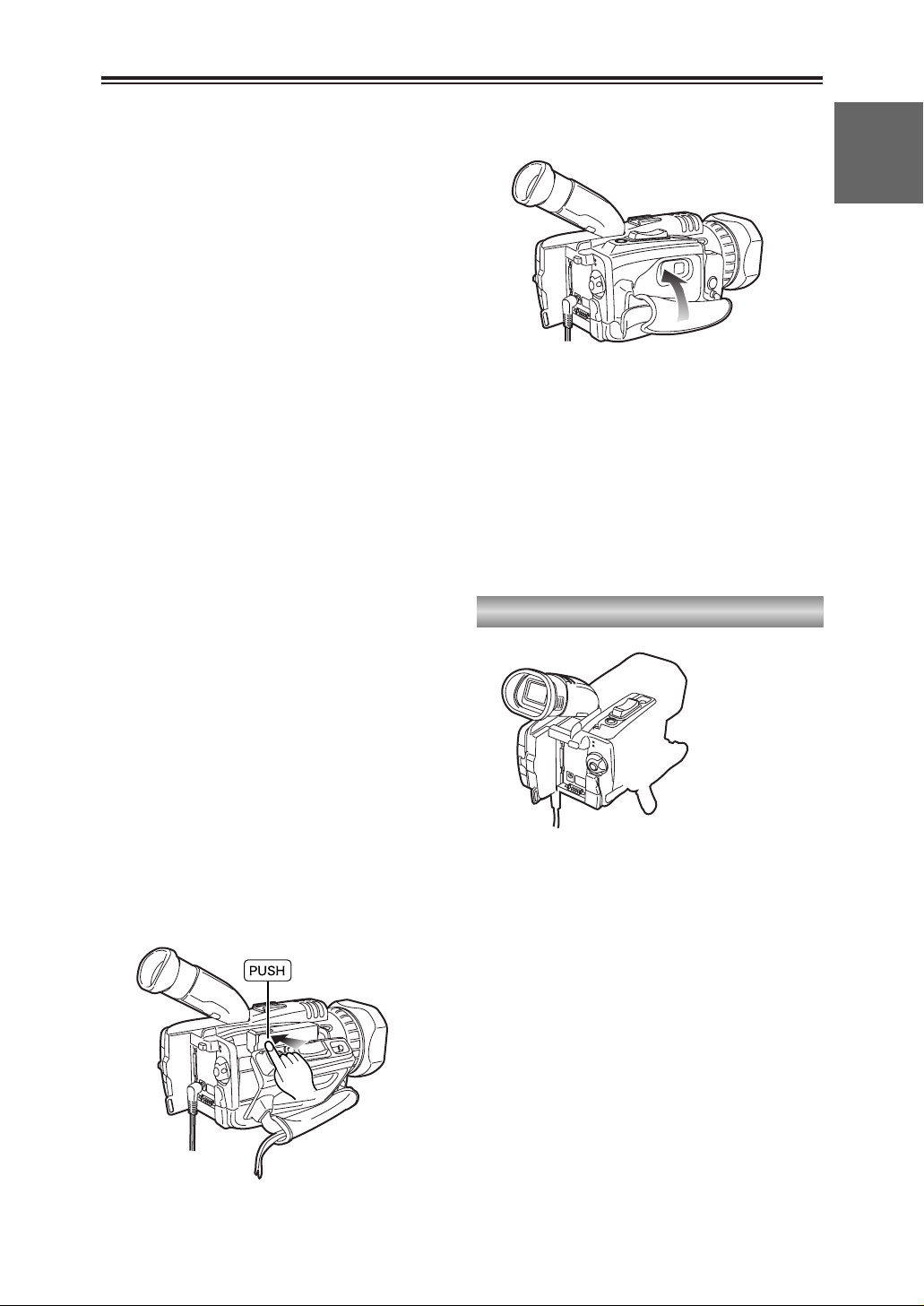
3
Press the part marked “PUSH” and close the
cassette holder.
When the holder is closed properly, the
cassette holder is retracted automatically.
4
Close the cassette cover after the cassette
holder has been completely retracted.
O Do not take hold of the cassette cover alone
to insert or remove tapes.
Insert and remove cassette tapes after
putting the camera-recorder down on a
stable, flat surface or hold it with both hands
to keep it stable.
O Do not forcibly push the cassette holder into
place as this may cause malfunctioning.
O Wait until the cassette holder is completely
retracted before closing the cassette cover.
3
4
Page 14
14
Checking the system operations (cont.)
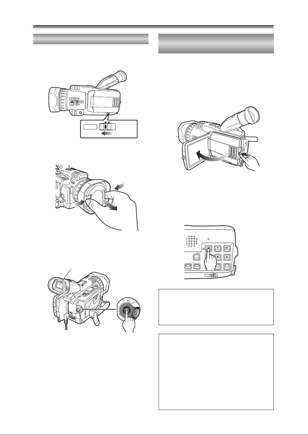
1
Set the AUTO/MANUAL selector switch to
AUTO.
2
Squeeze both sides of the lens cap and
remove it.
3
Look through the viewfinder and check what
you want to shoot.
4
Shooting starts when you press the
START/STOP (red) button on the POWER
lever.
Press this button again to pause shooting
(shooting pause mode).
Shooting
O
F
F
O
N
M
O
D
E
3
4
Viewfinder
1
MANUALAUTO
2
In the shooting pause mode, press the
6
button.
The last two or three seconds of the scenes
you have shot are now played back.
After playback, the shooting pause mode is
restored.
1
Open the LCD monitor while holding down
the panel locking button.
The LCD monitor can be opened to a
maximum angle of 90°.
Forcing it past this point will damage the
camera-recorder.
Checking what you have shot (rec check)
90°
You can conduct an image search (P36) by
holding down the 6 button in the shooting
pause mode.
Do not hold down the 6 button when
conducting a rec check.
Tape protection mode
If you leave the camera-recorder in the
shooting pause mode for 5 minutes or so, the
camera-recorder will automatically switch to
the tape protection mode and its power will
turn off.
However, when “STBY” has been selected as
the TAPE PROTECT item setting on the
OTHER FUNCTIONS screen using the
menus (P68-P71), the cylinder head will stop
instead of the power being turned off. (P80)
2
RESET
SEARCH
REC
COUNTER RESET MODE CHK ZEBRA OIS
DIGITAL ZOOM
BARS
MANUALAUTO
SEARCH
PHOTO SHOT
Page 15
15
BEFORE USE
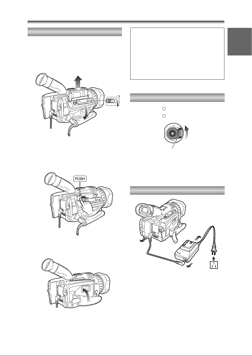
Hold down the white button and turn the
POWER lever to the OFF position.
The power is now turned off, and the CAMERA
lamp goes off.
2
Disconnect the DC cord from the DC input
socket.
O
F
F
O
N
M
O
D
E
POWER
CAMERA
VCR
Turning off the power
Disconnecting the power cord
3
Disconnect the DC cord and AC cord from
the AC adapter.
1
Disconnect the AC cord from the power
outlet.
3
3
1
2
Checking the system operations (cont.)
Removing the tape
1
Slide the OPEN/EJECT lever in the direction
of the arrow, and open the cassette cover.
When the cover is fully opened, the cassette
holder pops out automatically.
2
Take out the cassette tape.
3
Press the part marked “PUSH” and close the
cassette holder.
4
Close the cassette cover after the cassette
holder has been completely retracted.
2
OPEN/EJECT
1
3
4
O Check that the camera-recorder’s power is
on before sliding the OPEN/EJECT lever.
O Close the cassette cover if you are not
going to insert a cassette tape immediately
after removing another.
O Do not attempt to remove a tape while you
are recording. The cassette cover opens
but recording will continue, allowing outside
light and dust to adversely affect the tape.
Page 16

16
Adjusting the hand strap
1
Open the cover and adjust the strap length.
Adjust the hand strap to fit your hand.
Page 17
17
BEFORE USE
Attaching the shoulder strap
13
/16
inch (20 mm)
or more
13
/16 inch (20 mm)
or more
13
/16
inch (20 mm)
or more
13
/16 inch (20 mm)
or more
We recommended that you attach the shoulder
strap to help you avoid dropping the camerarecorder.
When the handle is not attached
When the handle is attached
Page 18
18
Cassette tapes
Preventing accidental erasure
To prevent erasing the recordings on a tape by
accident, set the tab on the cassette to SAVE.
REC
SAVE
$ We recommend that you use the following
mini DV cassette tapes with this camerarecorder.
AY-DVM30 (30 minutes in SP mode)
AY-DVM60 (60 minutes in SP mode)
$ Although the picture quality of material shot
in the LP mode is not bad, mosaic-like noise
may appear, limitations may apply to some of
the memory functions and/or regular
playback may not be possible when:
O a tape shot in the LP mode using this
camera-recorder is played back in another
digital video unit;
O a tape shot in the LP mode using another
digital video unit is played back in this
camera-recorder;
O a tape shot in the LP mode using this
camera-recorder is played back in another
digital video unit that does not have an LP
mode capability;
O slow or frame-feed playback is performed; or
O an image search is conducted
$ Audio dubbing cannot be performed in the LP
mode as the tracks on the tape are narrower
than the heads.
Larger flat area
Lens hood
Removing the lens hood
O Turn the lens hood counterclockwise to
remove it.
Attaching the lens hood
O Make sure that the larger flat part of the lens
hood is pointing upward, then fit it into place.
O Turn the lens hood clockwise to attach it.
Page 19
19
DESCRIPTION
OF PARTS
Page 20
20
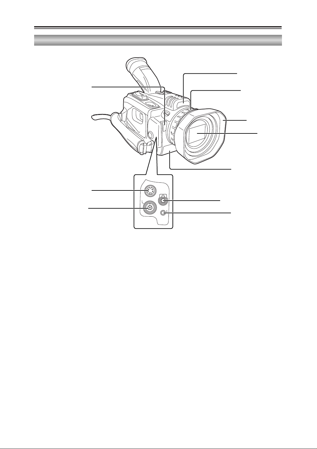
Description of parts (cont.)
Camera-recorder
S-VIDEO
IN/OUT
MIC
AV
IN/OUT
XLR ADAPTER
White balance sensor (P45)
S-VIDEO IN/OUT connector
(P56)
XLR ADAPTER connector
(P57, P59)
Tally lamp (P79, P84)
Focusing ring (P36,
P42, P44, P76)
Infrared light (P37, P80)
MIC jack (P57, P59, P64, P78)
AV IN/OUT jack (P56,
P58-P61, P74, P78, P80)
Lens hood (P18)
Lens (P10)
Page 21
21
DESCRIPTION
OF PARTS
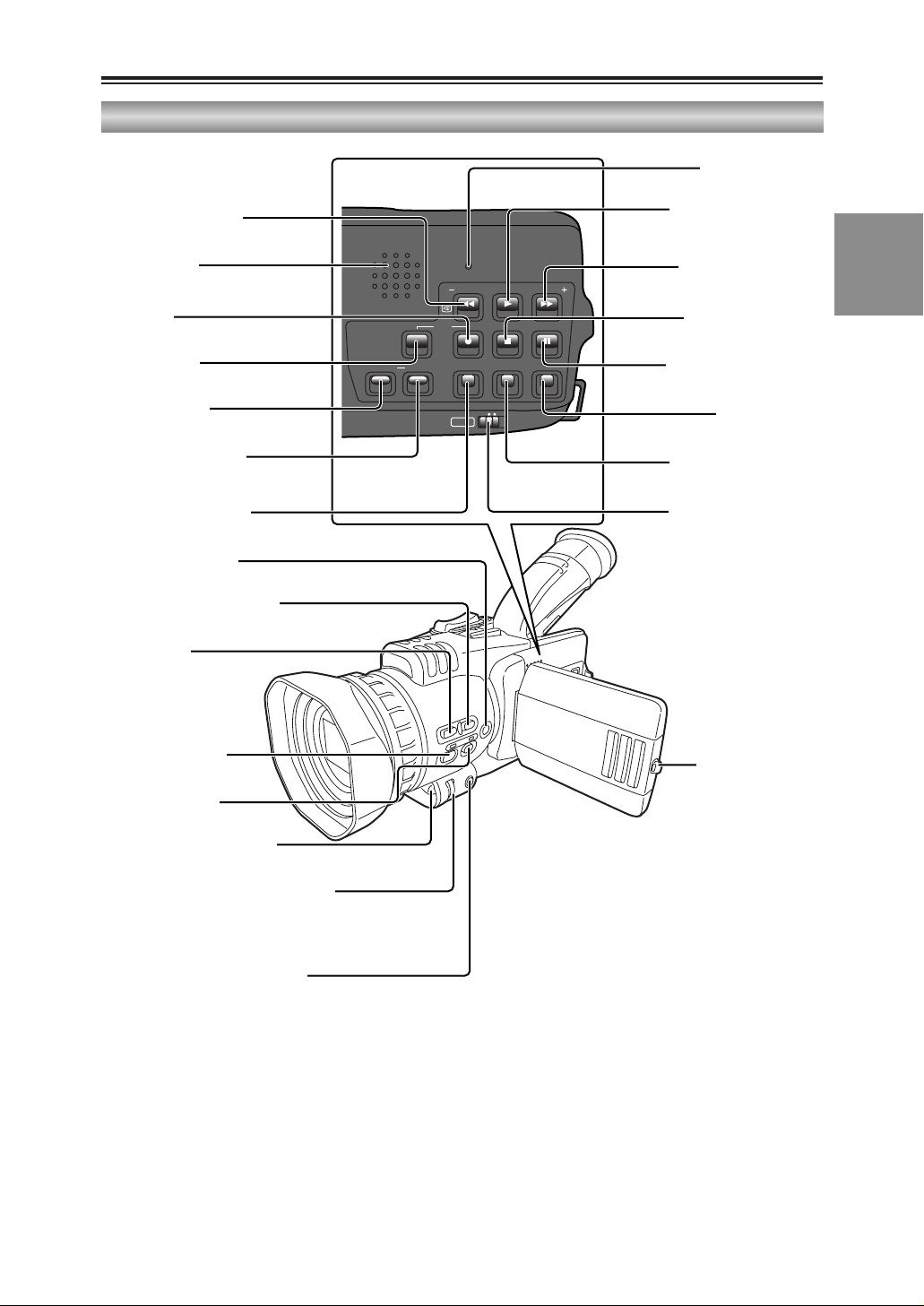
Description of parts (cont.)
Camera-recorder
SEARCH
RESET
SEARCH
DIGITAL ZOOM
REC
COUNTER RESET MODE CHK ZEBRA OIS
PHOTO SHOT
BARS
MANUALAUTO
–SEARCH (6) button
(P14, P36, P49, P51)
Built-in speaker
(P50, P59, P64)
REC button
(P60, P62)
REC sub button
(P60, P62)
COUNTER button
(P54, P65)
RESET button (counter)
(P28, P32, P34, P54)
SNS button (P37, P64)
USER2 button (P41, P52, P58,
P63, P64, P75)
USER3 button
(P41, P52, P58,
P63, P64, P75)
FOCUS button (P42)
WHITE BAL button
(P45, P46)
Remote control sensor (P25)
MENU button (P27, P29, P32, P34,
P47, P48, P68, P71)
MODE CHK button (P67)
Multi dial (P27, P29, P31-P34, P43, P44,
P47, P48, P50-P53, P66, P69, P70, P76)
RESET button (P84)
Digital zoom (1) button
(P36, P49, P51, P52, P61,
P62)
SEARCH + (5) button
(P36, P49, P51)
BARS ($) button (P39,
P49, P60-P62, P64)
PHOTO SHOT (;) button
(P39, P49, P51)
OIS button (P38)
ZEBRA button (P39, P64)
AUTO/MANUAL selector
switch (P14, P35, P42,
P43, P45, P46)
Panel locking button
(P14, P26, P49)
Page 22
22
Description of parts (cont.)
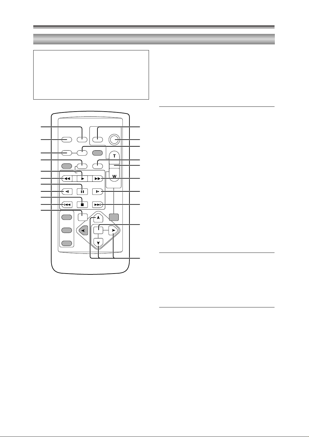
Wireless remote control unit
Note that the following buttons are for
functions that cannot be executed on the
camera-recorder.
OTITLE OMULTI/P-IN-P
OSELECT OSTORE
OOFF/ON OPB. ZOOM
O N
1. DATE/TIME button (P50)
2. OSD button (P50)
3. COUNTER button (P54)
4. RESET button (counter)
(P28, P32, P34, P54)
5. A.DUB button (P58)
6. REC button (P60, P62)
<Playback controls>
7. PLAY button (1)
21
(P49, P51, P52, P60-P62)
8. PAUSE button (;)
21
(P49, P51, P58)
9. C/REW button (6)
21
(P36, P49, P54)
10. STILL ADV button (E, D)
(P25, P51)
11. INDEX button (:, 9)
(P53, P74)
12. STOP button ($)
21
(P25, P49, P60-P62)
13. FF/B button (5)
21
(P36, P49, P54)
21
: During playback, these buttons function in
exactly the same way as the corresponding
buttons on the camera-recorder.
<Shooting/volume controls>
14. PHOTO SHOT button
22
(P39)
15. START/STOP button
22
(P35)
16. ZOOM/VOL buttons
22
(P50)
22
: During shooting, these buttons function in
exactly the same way as the corresponding
buttons on the camera-recorder.
17. VAR.SEARCH button (P52)
18. MENU button
(P27, P29, P31, P32, P34, P47, P48, P68,
P71)
19. [V] [B], [M] buttons
(P27, P29, P31-P34, P47, P48, P52, P53,
P69, P70)
OSD
COUNTER
RESET TITLE
STILL ADV
PAUSE
STILL ADV
INDEX
SELECT
STORE
OFF/ON
P.B.DIGITAL
VAR.
SEARCH
– VOL +
PB.
ZOOM
MENU
SET
ITEM
STOP INDEX
MULTI/
P-IN-P
REC A.DUB
PLAY
C
/REW FF/
B
ZOOM
DATE/
TIME
PHOTO
SHOT
START/
STOP
114
215
3
4
6
7
9
8
10
12
11
17
5
16
13
10
11
18
19
Page 23
23
PREPARATION
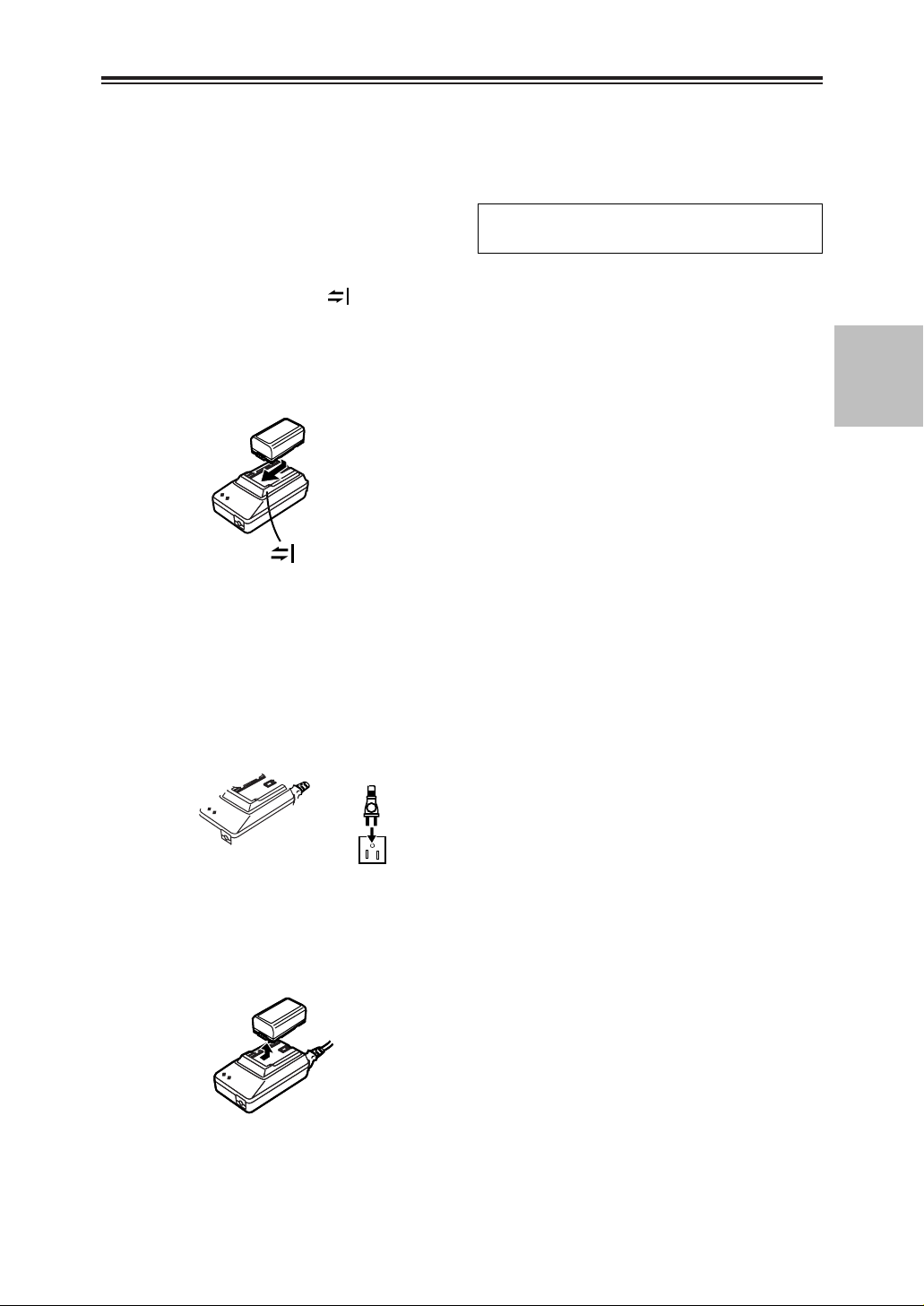
Battery
Before using the battery, fully charge it in the
AC adapter.
We recommend that you keep a spare battery
with you whenever you use the battery to run
the camera-recorder.
Charging time Continuous recording time
1
Align the battery with the “” marking on
the AC adapter, place it flat, and slide it in
the direction shown below.
O Before doing this, disconnect the DC cord
from the AC adapter as the battery cannot
be charged if it is connected.
2
Connect the AC cord to the power outlet.
O The POWER lamp and CHARGE lamp on
the AC adapter light, and charging begins.
O If the CHARGE lamp does not light when
the battery is placed in the AC adapter,
remove the battery and place it in the
adapter once again.
3
When the battery has been charged, the
CHARGE lamp on the AC adapter goes off.
4
Slide the battery, and remove it.
Page 24
24
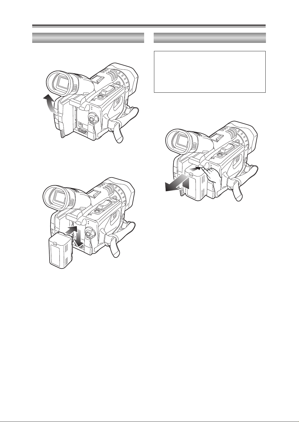
1
Raise the viewfinder.
2
Press the battery straight against the
camera-recorder body and slide it down until
it clicks into place.
3
Return the viewfinder to its original position.
O Turn the POWER lever to the OFF position,
check that the POWER lamp
(CAMERA/VCR) has gone off, and then
remove the battery.
O Support the battery with your hand so that it
does not drop off.
Battery (cont.)
Mounting
To remove the battery, hold down the battery
release button and slide it up.
Removing
Page 25

25
PREPARATION
Remote control unit
Setting the remote control unitInstalling the battery
When two camera-recorders are used
simultaneously, either [VCR1] or [VCR2] can be
set for this camera-recorder and the wireless
remote control unit so that the remote control
unit will not be used to operate the wrong
camera-recorder by mistake.
O The remote control sensor used for this is
located at the lower side of the lens on the
camera recorder. Point the wireless remote
control unit towards the sensor when
operating the camera-recorder with it.
Setting procedure
O Wireless remote control unit
Press the STOP ($) and STILL ADV (D)
buttons at the same time to set the remote
control unit for use with VCR1. Alternatively,
press the STOP ($) and STILL ADV (E)
buttons at the same time to set the remote
control unit for use with VCR2.
When the battery in the remote control unit is
replaced, the remote control unit is set for
use with VCR1.
O Camera-recorder
Use the menus (P68-P71) to set the
REMOTE item on the OTHER FUNCTIONS
screen. (P79)
If different settings are used for the camerarecorder and remote control unit, “REMOTE” will
light up in red on the viewfinder and LCD
monitor.
Page 26
26
Viewfinder
1
Set the POWER lever to the ON position,
and check that images appear in the
viewfinder.
O Keep the LCD monitor closed.
2
Adjust the viewfinder’s angle so that the
screen is positioned where it is easiest to
see.
3
Adjust the diopter adjustment lever so that
the characters on the viewfinder screen are
seen most clearly.
Do not point the viewfinder at the sun.
Doing so may damage the parts inside.
This camera-recorder offers a choice of
viewfinders: a viewfinder with a small LCD
screen and one with a 3.5-inch LCD monitor.
Use the viewfinder that best suits the application
and shooting conditions.
O The brightness and hue may differ between
the images appearing on the viewfinder and
LCD monitor and those displayed on a TV
monitor.
To see how the final images will appear,
check them on a TV monitor.
Using the viewfinder
Diopter adjustment
lever
Viewfinder
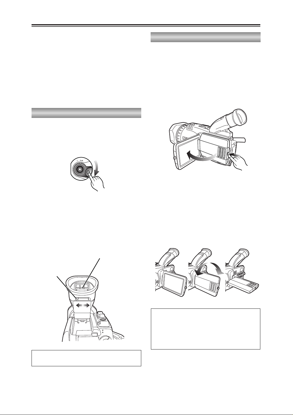
Using the LCD monitor
1
Set the POWER lever to the ON position.
2
Open the LCD monitor while holding down
the panel locking button.
The LCD monitor can be opened to a
maximum angle of 90°.
Forcing it past this point will damage the
camera-recorder.
3
Position the LCD monitor where it is easiest
to see.
O The monitor can be rotated by 180
degrees toward the lens and 90 degrees
toward you.
Forcing the monitor beyond these
angles or attempting to close the
monitor while it has been rotated by 90
degrees will damage the camerarecorder.
180° 90°
90°
O
F
F
O
N
M
O
D
E
O When closing the LCD monitor, ensure that
it is closed securely.
O When the LCD monitor is rotated toward
the lens (for self-portrait shooting), the
viewfinder and LCD monitor will light up at
the same time.
Page 27
27
PREPARATION
When the [M] button on the remote control unit is used to make adjustments, the level meter
reading starts changing in the opposite direction once it has reached the maximum (or minimum)
position.
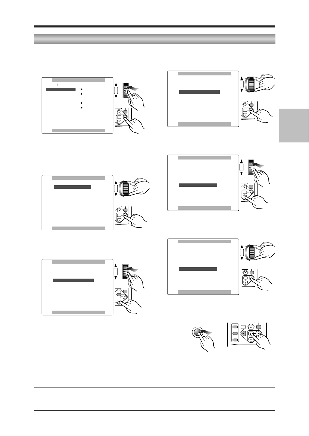
Viewfinder (cont.)
1
Use the menus (P68-P71) to select “YES” as
the LCD/EVF SET item setting on the
DISPLAY SETUP screen.
Adjusting the screen display
2
The LCD/EVF SET screen with “LCD
BRIGHTNESS” selected appears. Turn the
multi dial to adjust the brightness of the LCD
monitor screen.
DISPLAY SETUPDISPLAY SETUP
LCD/EVF SETLCD/EVF SET –––––––– YES YES
SELF SHOOT NORMAL
EVF MODE AUTO
EVF COLOR ON
PUSH MENU TO RETURNPUSH MENU TO RETURN
SHUTTER/IRIS
VOL/JOG
PUSH
LCD/EVF SETLCD/EVF SET
LCD BRIGHTNESS LCD BRIGHTNESS
[–]
? ? ? ?
––––[+]
LCD COLOR LEVEL
[–]
? ? ? ?
––––[+]
EVF BRIGHTNESS
[–]
? ? ? ?
––––[+]
PUSH MENU TO RETURNPUSH MENU TO RETURN
SHUTTER/IRIS
VOL/JOG
PUSH
3
Upon completion of the settings, press the
multi dial to select “LCD COLOR LEVEL.”
LCD/EVF SETLCD/EVF SET
LCD BRIGHTNESS
[–]
? ? ? ?
––––[+]
LCD COLOR LEVEL LCD COLOR LEVEL
[–]
? ? ? ?
––––[+]
EVF BRIGHTNESS
[–]
? ? ? ?
––––[+]
PUSH MENU TO RETURNPUSH MENU TO RETURN
SHUTTER/IRIS
VOL/JOG
PUSH
6
Turn the multi dial to adjust the brightness of
the viewfinder screen.
LCD/EVF SETLCD/EVF SET
LCD BRIGHTNESS
[–]
? ? ? ?
––––[+]
LCD COLOR LEVEL
[–]
? ? ? ?
––––[+]
EVF BRIGHTNESS EVF BRIGHTNESS
[–]
? ? ? ?
––––[+]
PUSH MENU TO RETURNPUSH MENU TO RETURN
SHUTTER/IRIS
VOL/JOG
PUSH
5
Upon completion of the settings, press the
multi dial to select “EVF BRIGHTNESS.”
LCD/EVF SETLCD/EVF SET
LCD BRIGHTNESS
[–]
? ? ? ?
––––[+]
LCD COLOR LEVEL
[–]
? ? ? ?
––––[+]
EVF BRIGHTNESS EVF BRIGHTNESS
[–]
? ? ? ?
––––[+]
PUSH MENU TO RETURNPUSH MENU TO RETURN
SHUTTER/IRIS
VOL/JOG
PUSH
4
Turn the multi dial to adjust the color level of
the LCD monitor screen.
LCD/EVF SETLCD/EVF SET
LCD BRIGHTNESS
[–]
? ? ? ?
––––[+]
LCD COLOR LEVEL LCD COLOR LEVEL
[–]
? ? ? ?
––––[+]
EVF BRIGHTNESS
[–]
? ? ? ?
––––[+]
PUSH MENU TO RETURNPUSH MENU TO RETURN
SHUTTER/IRIS
VOL/JOG
PUSH
7
Press the MENU button three times to exit
the menu mode.
MENU
PB.
ZOOM
MENU
SET
ITEM
PB.
ZOOM
MENU
SET
ITEM
PB.
ZOOM
MENU
SET
ITEM
PB.
ZOOM
MENU
SET
ITEM
PB.
ZOOM
MENU
SET
ITEM
PB.
ZOOM
MENU
SET
ITEM
SELECT
VAR.
PB.
SEARCH
STORE
OFF/ON
P.B.DIGITAL
ZOOM
MENU
SET
ITEM
Page 28

28
Viewfinder (cont.)
Adjusting the screen display
O If the RESET button (counter) is pressed
when it is possible to change the settings
by selecting the LCD/EVF SET item, the
values set for those items (LCD
BRIGHTNESS and COLOR LEVEL, and
EVF BRIGHTNESS) can be returned to the
factory settings.
O When “ON” is selected as the setting for the
EVF MODE item on the DISPLAY SETUP
screen, the images will always be displayed
on the viewfinder even if the LCD monitor is
open. (P79)
O Using the EVF COLOR item on the
DISPLAY SETUP screen, either color or
black and white can be selected for
displaying the viewfinder images. (P79)
No matter whether color or black and white
is selected, the images will have the same
resolution.
O When you press the USER button to which
the EVF DTL function has been allocated,
the contours of the images in the viewfinder
and LCD monitor are emphasized, making
it easier to bring the subject into focus.
(P75)
Note that the contours of the images will
still be emphasized to make focusing easier
even if “ON” has been selected as the EVF
DETAIL item setting on the DISPLAY
SETUP screen. (P79)
OSD
COUNTER
RESET TITLE
MULTI/
P-IN-P
REC A.DUB
ZOOM
DATE/
TIME
PHOTO
SHOT
START/
STOP
RESET
SEARCH
REC
COUNTER RESET MODE CHK ZEBRA OIS
DIGITAL ZOOM
BARS
MANUALAUTO
SEARCH
PHOTO SHOT
Page 29
29
PREPARATION
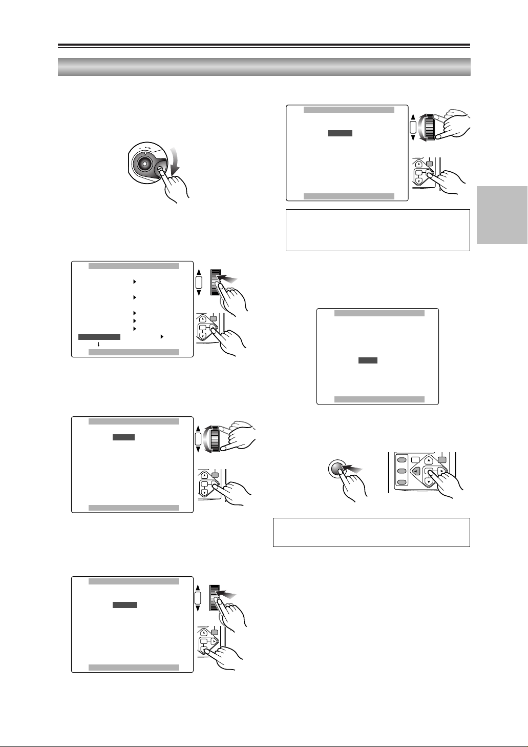
5
Turn the multi dial to set DEC.
6
In the same way, use the multi dial to set 25
for “DAY,” 17 for “HOUR” and 20 for “MIN.”
O The 24-hour system is used for the time.
An error will gradually develop in the time, so
check that the time is correct before shooting.
Adjusting the calendar
OTHER FUNCTIONSOTHER FUNCTIONS
REMOTE VCR1
DV CONTROL OFF
DV CMD SEL REC P
REC LAMP OFF
BEEP SOUND OFF
CLOCK SETCLOCK SET –––––––– YES YES
PUSH MENU TO RETURNPUSH MENU TO RETURN
SHUTTER/IRIS
VOL/JOG
PUSH
CLOCK SETCLOCK SET
YEAR 2004
MONTHMONTH DEC DEC
DAY 24
HOUR 13
MIN. 7
PUSH MENU TO RETURNPUSH MENU TO RETURN
SHUTTER/IRIS
VOL/JOG
PUSH
CLOCK SETCLOCK SET
YEAR 2004
MONTH DEC
DAY 25
HOUR 17
MIN.MIN. 20 20
PUSH MENU TO RETURNPUSH MENU TO RETURN
CLOCK SETCLOCK SET
YEARYEAR 2004 2004
MONTH APR
DAY 24
HOUR 13
MIN. 7
PUSH MENU TO RETURNPUSH MENU TO RETURN
SHUTTER/IRIS
VOL/JOG
PUSH
CLOCK SETCLOCK SET
YEAR 2004
MONTHMONTH APR APR
DAY 24
HOUR 13
MIN. 7
PUSH MENU TO RETURNPUSH MENU TO RETURN
SHUTTER/IRIS
VOL/JOG
PUSH
Time data
This shows you how to adjust the calendar to
5:20 PM on December 25, 2004.
2
Use the menus (P68-P71) to select “YES” as
the CLOCK SET item setting on the OTHER
FUNCTIONS screen.
3
The CLOCK SET screen with “YEAR”
selected appears. Turn the multi dial to set
2004.
4
Press the multi dial to move the setting item
to “MONTH.”
Any year from 2000 to 2089 can be set.
7
Press the MENU button three times to exit
the menu mode.
MENU
1
Set the POWER lever to the ON position.
O
F
F
O
N
M
O
D
E
JAN (January), FEB (February), MAR (March), APR
(April), MAY (May), JUN (June), JUL (July), AUG
(August), SEP (September), OCT (October), NOV
(November), DEC (December)
PB.
ZOOM
MENU
SET
ITEM
PB.
ZOOM
MENU
SET
ITEM
SELECT
VAR.
PB.
SEARCH
PB.
ZOOM
MENU
SET
ITEM
STORE
OFF/ON
P.B.DIGITAL
ZOOM
MENU
SET
ITEM
PB.
ZOOM
MENU
SET
ITEM
Page 30

30
The calendar data (year/month/day/hours/
minutes) is kept in the memory by the internal
battery.
When the “” display appears on the
viewfinder and LCD monitor screen, it means
that the battery has run out.
Follow the steps below to charge the battery.
Set the date and time after the battery is fully
recharged.
1
Connect the AC adapter to the camerarecorder. (P12)
O Keep the LCD monitor closed.
2
Leave the POWER lever at the OFF position.
3
Leave the camera-recorder like this for about
4 hours.
O The internal battery is charged during this
time.
Time data (cont.)
Charging the internal battery
Page 31

31
PREPARATION
Time data (cont.)
By setting the user’s bit, you can store 8-digit
information (such as the date and time) in the
hexadecimal format on the tape’s sub code
track.
The user’s bit settings are automatically saved
in the memory and retained even after the
power has been turned off.
3
Turn the multi dial to move to the UB
PRESET item.
5
The screen shown below appears. Set the
user’s bit using the multi dial.
Turn the multi dial and select the user’s bit
characters.
O Numbers from 0 to 9 and letters from A to
F can be used as the characters that
make up the user’s bit.
Press the multi dial to move to the next digit.
Setting the user’s bit
1
Set the POWER lever to the ON position.
O
F
F
O
N
M
O
D
E
SHUTTER/IRIS
VOL/JOG
PUSH
PB.
ZOOM
MENU
SET
ITEM
Page 32

32
Time data (cont.)
7
The screen shown below appears. Turn the
multi dial to select “YES.”
8
The user’s bit is entered when the multi dial
is pressed.
Setting the user’s bit
UB PRESETUB PRESET
PRESET OK?
NONO ––– PUSH JOG
YES ––– PUSH JOG
SHUTTER/IRIS
VOL/JOG
PUSH
PB.
ZOOM
MENU
SET
ITEM
Page 33

33
PREPARATION
Perform the settings related to the time code
using the items below on the RECORDING
SETUP screen. (P76, P77)
OTCG
OFIRST REC TC
OTC PRESET
O1394 TC REGEN (the menu items appear in
the VCR mode)
O In the VCR mode, the settings of the items
listed here cannot be changed if “ON” has
been selected as the 1394 TC REGEN item
setting.
Time data (cont.)
Setting the time code
Specifying the time code
1
Set the POWER lever to the ON position.
O
F
F
O
N
M
O
D
E
SHUTTER/IRIS
VOL/JOG
PUSH
RECORDING SETUPRECORDING SETUP
FIRST REC TCFIRST REC TC REGEN REGEN
PRESETPRESET
TC PRESET ––––
UB MODE USER
DATE TCG DATE TCG
UB PRESET ––––
ONE–SHOT REC OFF
REC TIME 0.5S
PUSH MENU TO RETURNPUSH MENU TO RETURN
2
Use the menus (P68-P71) to select
“PRESET” as the FIRST REC TC item
setting on the RECORDING SETUP screen.
You can record a value of your choice as the
initial setting for the time code to be used at the
start of recording.
3
Turn the multi dial to move to the TC
PRESET item.
RECORDING SETUPRECORDING SETUP
FIRST REC TC PRESET
TC PRESETTC PRESET –––––––– YES YES
UB MODE USER
UB PRESET ––––
ONE–SHOT REC OFF
REC TIME 0.5S
PUSH MENU TO RETURNPUSH MENU TO RETURN
SHUTTER/IRIS
VOL/JOG
PUSH
4
Press the multi dial to move 1to “YES.”
RECORDING SETUPRECORDING SETUP
FIRST REC TC PRESET
TC PRESETTC PRESET –––––––– YES YES
UB MODE USER
UB PRESET ––––
ONE–SHOT REC OFF
REC TIME 0.5S
PUSH MENU TO RETURNPUSH MENU TO RETURN
SHUTTER/IRIS
VOL/JOG
PUSH
5
The screen shown below appears. Use the
multi dial to set the time code.
Turn the multi dial to specify the time code.
TC PRESETTC PRESET
10h00m00s00f
PUSH MENU TO RETURNPUSH MENU TO RETURN
SHUTTER/IRIS
VOL/JOG
PUSH
TC PRESETTC PRESET
00h00m00s00f
PUSH MENU TO RETURNPUSH MENU TO RETURN
PB.
ZOOM
MENU
SET
ITEM
PB.
ZOOM
MENU
SET
ITEM
PB.
ZOOM
MENU
SET
ITEM
PB.
ZOOM
MENU
SET
ITEM
Page 34

34
Time data (cont.)
Specifying the time code
Press the multi dial to move to the next digit.
PB.
Page 35

35
SHOOTING
Regular shooting
Before shooting, check that the camerarecorder is operating properly.
Check the equipment as warranted by the
shooting conditions.
$ Battery (P23)
Have a fully charged battery ready.
We also recommend that you keep a spare
battery on hand.
$ Cassette tape (P13, P18)
Check that the cassette tape can be used for
recording:
O Is the cassette’s accidental erasure
prevention tab not set to the SAVE
position?
O Is there not already any important material
on the tape?
O Is the cassette cover closed securely?
$ Viewfinder (P26)
Check whether the viewfinder’s diopter
adjustment has been made.
$ Zoom/focus/iris
O Check that motor-driven zooming is
possible. (P36)
O Check that the focusing can be performed
both automatically and manually. (P42)
O Check that the lens iris operations can be
performed automatically and manually.
(P44)
$ Time data (P29-P34)
O Check that the calendar and time have
been set correctly.
O Check that the time code and user’s bit
have been set correctly.
Preparation and inspections
1
Set the AUTO/MANUAL selector switch to
the AUTO position.
2
Squeeze both sides of the lens cap and
remove it.
3
Look through the viewfinder and check what
you want to shoot.
4
Shooting starts when you press the
START/STOP (red) button on the POWER
lever.
Press this button again to pause shooting
(shooting pause mode).
Shooting
3
4
O
F
F
O
N
M
O
D
E
Page 36

The digital zoom function is made operational
by pressing the DIGITAL ZOOM button in the
shooting pause mode.
When “k24” is selected as the D.ZOOM item
(P76) setting on the SW MODE screen, the
digital zoom function works at the following
magnification levels each time this button is
pressed: k1.25 5 k1.5 5 k1 (OFF). Zooming
at a maximum level of k24 is possible at this
setting.
If, on the other hand, “k160” is selected as the
item’s setting, the digital zoom function works at
the following magnification levels each time this
button is pressed: k2 5 k5 5 k10 5 k1
(OFF). Zooming at a maximum level of k160 is
possible at this setting.
The zoom position is displayed at all times at
the top right of the screen, and the magnification
level of the digital zoom also appears when the
digital zoom function is working. (P65)
O The magnification level cannot be changed
during shooting.
O When shooting with the digital zoom function,
you cannot obtain the same image quality as
you can with normal (optical) zooming.
When “ZOOM” has been selected as the
FOCUS RING item setting on the SW MODE
screen using the menus (P68-P71), zooming
operations can be performed using the focus
ring but only when shooting in the auto focus
mode. (P76)
36
Shooting techniques for different targets
DIGITAL ZOOM
For shooting at a low angle, you can attach the
accessory handle (P16) and use the
START/STOP button on the lens.
The recording operation of this button can be
set using the FRONT S/S INHIBIT item on the
SW MODE screen. (P76)
To check what you have shot straight away,
conduct a rec check (P14).
To find specific scenes among the ones that you
have shot so far, conduct an image search while
the shooting pause mode is established.
Image search comes in handy when you want to
continue shooting from a particular scene you
have found (shooting with frame-to-frame
continuity).
START/STOP button
(on lens)
Low-angle shooting
This camera-recorder comes with a k16 optical
zoom. Press the ZOOM buttons gently for slow
zooming; press them more forcefully for fast
zooming.
The zoom speed resulting when the buttons are
pressed gently can be set using the ZOOM
MODE item (P76) on the SW MODE screen.
Zoom functions
1
In the shooting pause mode, hold down the
5
or 6button.
While the button is held down, the tape is
played back in the forward or reverse
direction.
SEARCH
RESET
SEARCH
DIGITAL ZOOM
REC
COUNTER RESET MODE CHK ZEBRA OIS
PHOTO SHOT
BARS
MANUALAUTO
2
When you have found the scene you are
looking for, release the button.
Upon completion of the image search,
operation returns to the shooting pause
mode.
Searching specific scenes (image search)
W button
(for zooming out)
DIGITAL ZOOM
button
T button
(for zooming in)
Focus ring
MULTI/
REC A.DUB
P-IN-P
C
/REW FF/
STILL ADV
INDEX
PLAY
PAUSE
STILL ADV
STOP INDEX
– VOL +
B
Page 37

IR
SUPER_IR
COLOR_NS
Lighted
Off
1/60 sec.
1/4 sec.
Black and
white
Color
High-sensitivity
shooting mode
Shutter
speed
IR light
Recorded
image
37
SHOOTING
Shooting techniques for different targets (cont.)
Self-portrait shooting
When the LCD monitor is opened and turned
180 degrees toward the lens to take shots of
yourself, the images shot may appear differently
from how you would normally.
When “MIRROR” has been selected as the
SELF SHOOT item setting on the DISPLAY
SETUP screen using the menus (P68-P71), an
image with the left and right sides reversed will
appear on the LCD monitor. This way, it feels as
if you were looking at yourself in a mirror, which
makes it easier to check what you are shooting.
(P79)
However, even if you take self-portrait shots in
the mirror mode, the images recorded on the
tape will be exactly like the ones you would
normally shoot (i.e. not mirror images).
When shooting in the mirror mode, the
information displayed on the viewfinder and
LCD monitor is limited to the following.
¥ : Shooting
¥
;
: Shooting pause
: Remaining battery charge
: Warning
If is displayed, return the LCD monitor to its
original position, and check the contents of the
warning.
Recording the time stamp
By selecting “REC” as the TIME STAMP setting
on the RECORDING SETUP screen using the
menus (P68-P71), the shooting date and time
can be superimposed on the images shot and
recorded on the tape. (P76)
When “REC” is selected as the TIME STAMP
item setting, appears on the screen.
R
O The time stamp cannot be recorded when
“k160” has been selected as the D.ZOOM
item setting on the SW MODE screen. (P76)
O When the audio level is adjusted (P47, P48)
during actual shooting, the time stamp
recording will be suspended while the
adjustments are being made.
High-sensitivity shooting (SNS)
This camera-recorder comes with a highsensitivity shooting function to enable shooting
in very dark places.
You can shoot scenes in three high-sensitivity
shooting modes, which you could not capture
using a regular camera, by combining the light
in the infrared ray region (IR light) with the
shutter speed.
Press the SNS button for high-sensitivity
shooting.
Switch back to regular shooting by pressing the
SNS button again.
The high-sensitivity shooting modes are
selected using the SNS item on the SW MODE
screen. (P76)
O High-sensitivity shooting cannot be
performed during regular shooting even by
pressing the SNS button. Temporarily stop
shooting first, and then press the SNS
button.
Infrared light
SNS buttonLens hood
SNS: Super Night Shooting system
Page 38

If you are going to hold the camera to shoot,
you can use the vibration reduction function to
achieve shooting with minimal vibration (camera
shake).
appears on the screen when this function is
working.
To release the function, press the OIS (Optical
Image Stabilizer) button. When the OIS button
is pressed again, the function is reactivated.
If you use a tripod, you can obtain natural
images by shooting with the vibration reduction
function released.
Vibration reduction function
O It may not be possible to reduce the vibration
at such times when the vibration is severe or
when a moving subject is being tracked and
shot at the same time.
O The vibration reduction function may not
work properly when the digital zoom function
is working.
38
Shooting techniques for different targets (cont.)
Wind noise reduction
When “ON” has been selected as the WIND
CUT item setting on the RECORDING SETUP
screen using the menus (P68-P71), the noise
created by wind blowing into the microphone on
very windy days can be reduced. (P76)
When the wind noise reduction is activated,
WIND CUT appears on the screen.
O The wind noise reduction function works for
both the internal microphone and external
microphone.
O If there is any bass sound, some of it may be
reduced along with the wind noise.
Movie-like shooting
When “4. MOVIE-LIKE” has been selected as
the SCENE FILE item setting on the SCENE
FILE screen using the menus (P68-P71), you
can shoot movie-like images. (P73)
When SUPER_IR or COLOR_NS has been
selected as the high-sensitivity shooting
mode, images are shot with the CCD taking
about 16 times more time than usual to
accumulate the signals.
As a result, very small brilliant points that are
not usually visible may be recorded as the
images: this is normal and does not indicate
an error or malfunctioning.
O The aperture (IRIS) cannot be adjusted with
the multi dial in the IR and SUPER_IR
modes; however, both the aperture and gain
can be adjusted in the COLOR_NS mode.
(P44)
O You can change the lighting control of the IR
light using the IR LED item on the OTHER
FUNCTIONS screen. (P80)
O Do not look directly at the IR light when it is
on.
O Do not cover the IR light with your hand or
anything else.
O When using the camera-recorder’s IR light,
remove the lens hood before you start to
shoot. (P18)
O For shooting at an even higher sensitivity, we
recommend that you use the optional IR light
(AG-YRL30G).
O Performing high-sensitivity shooting may give
rise to such problems as after-image, a
deterioration in the image quality and
difficulties in focusing.
COUNTER RESET MODE CHK ZEBRA OIS
RESET
SEARCH
REC
DIGITAL ZOOM
BARS
MANUALAUTO
SEARCH
PHOTO SHOT
Page 39

39
SHOOTING
Shooting techniques for different targets (cont.)
Photo shots
You can record still pictures on tape just as if
you were taking snapshots with an ordinary
camera.
When the PHOTO SHOT button is pressed in
the shooting pause mode, a still picture lasting
for about 7 seconds is recorded.
Once the still picture has been recorded, the
camera-recorder is set to the shooting pause
mode.
A photo index for images recorded using the
photo shot function is created, enabling you to
perform a photo index search when the tape is
played back to find any still pictures you have
recorded. (P53)
O While shooting is in progress, still pictures
cannot be recorded even when the PHOTO
SHOT button is pressed.
Zebra pattern
When the ZEBRA button is pressed, parts that
may be whitened out due to overexposure can
be displayed in stripes.
O Parts that are extremely bright
O Parts that reflect a lot of light
By adjusting the iris and shutter speed in the
manual mode to remove the areas with zebra
patterns, you can obtain images with minimal
whitened-out areas.
You can set the brightness level at which the
zebra patterns are to be displayed by using the
menus (P68-P71) and the ZEBRA DETECT
item on the DISPLAY SETUP screen. (P78)
The markers are displayed when the ZEBRA
button is pressed again.
Color bars
When the BARS button is pressed during
shooting or in the shooting pause mode, color
bars (complying with the SMPTE standard),
which come in handy for adjusting the picture
quality of TV and external monitor images, can
be displayed.
When the BARS button is pressed again, the
original image is restored.
When the ID information in the ID SET item on
the RECORDING SETUP screen have been set
using the menus (P68-P71), the ID information
will be displayed on the screen along with the
color bars. (P76)
If the START/STOP button is now pressed, the
images with ID information superimposed onto
the color bars can be recorded on a tape.
Markers
When the ZEBRA button is pressed again while
zebra patterns are displayed, markers will
appear at the center of the screen.
When these markers are displayed, the video
level is indicated at the bottom left of the screen.
The video level is displayed as a percentage
from 0 to 99, and “99:” appears when the level
exceeds 99.
The regular screen is restored when the ZEBRA
button is pressed again.
O The video level and video level detection
area will not be displayed when the digital
zooming is performed. (P36)
O The color bars will not be displayed when the
digital zooming is performed. (P36)
99
Video level detection area
Video level
Markers
RESET
SEARCH
REC
COUNTER RESET MODE CHK ZEBRA OIS
DIGITAL ZOOM
BARS
MANUALAUTO
SEARCH
PHOTO SHOT
OSD
COUNTER
MULTI/
P-IN-P
DATE/
PHOTO
TIME
SHOT
RESET TITLE
REC A.DUB
START/
STOP
ZOOM
OL +
RESET
SEARCH
REC
COUNTER RESET MODE CHK ZEBRA OIS
DIGITAL ZOOM
BARS
MANUALAUTO
SEARCH
PHOTO SHOT
RESET
SEARCH
REC
COUNTER RESET MODE CHK ZEBRA OIS
DIGITAL ZOOM
BARS
MANUALAUTO
SEARCH
PHOTO SHOT
Page 40

40
Shooting techniques for different targets (cont.)
Frame-by-frame shooting
When “ON” has been selected as the ONESHOT REC item setting on the RECORDING
SETUP screen using the menus (P68-P71),
frame-by-frame shooting can be performed.
(P77)
The number of seconds for the shooting is set
using the REC TIME item on the same screen.
When the START/STOP button is pressed,
shooting is initiated for the number of seconds
set, and then the shooting pause mode is
established.
O When the frame-by-frame shooting mode is
set, an asterisk (2) at the left of the VCR’s
operating mode on the screen blinks. When
recording is started, the asterisk stops
blinking and lights.
O Even if the frame-by-frame shooting mode
has been set, it is cancelled when the power
is turned OFF.
Ao Ae BoBe Co Ce Do De EoEe Fo FeGoGeHo He Io Ie Jo Je
ABCDEFGH I J
Field and frame shooting
This camera-recorder normally shoots scenes
using field recording (60 fields per second).
When “FRAME” has been selected as the REC
MODE setting for the SETTING item on the
SCENE FILE screen using the menus (P68-
P71), scenes can be shot using frame recording
(30 frames per second). (P73)
When playing back still pictures, high-quality
images can be obtained.
O If normal (moving image) playback is
performed, the images will appear jerky.
When you are going to shoot scenes using
frame recording, we recommend that you set
the shutter speed to 1/60. (P43)
Field recording
Frame recording
Changing the image size
This camera-recorder allows you to change the
size (aspect ratio) of the images recorded on
tape.
Use the menus (P68-P71) to select the desired
setting for the ASPECT CONV item on the
CAMERA SETUP screen. (P73)
NORMAL:
Images are recorded with the standard 4:3
aspect ratio.
LETTER BOX:
Images are recorded with a 16:9 aspect ratio.
Black bands are recorded at the top and
bottom of the screen.
SQUEEZE:
The camera images are squeezed
horizontally and recorded. When images
recorded in this mode are played back on a
TV monitor that supports the wide screen
format, they are displayed with the 16:9
aspect ratio.
When SQUEEZE has been selected as the
item’s setting, “SQU” is displayed on the
screen.
O When the mode is switched to SQUEEZE,
the screen image may be disrupted for an
instant. This is not a sign of
malfunctioning.
O The image quality may deteriorate when
images recorded at the SQUEEZE setting
are played back.
Page 41

This function locks the shutter speed and iris for
as long as you shoot when you press the USER
button (P75) to which the AE lock function has
been allocated.
When you zoom in on a subject so that it
appears larger on the screen and then press the
USER button, the shutter speed and iris that are
suitable for the subject are fixed.
Even when the brightness of the background
changes, you can shoot the subject at the same
brightness level.
appears on the screen while the AE lock
function is working.
AE LOCK
AE lock function
41
SHOOTING
Shooting techniques for different targets (cont.)
Using the USER buttons
You can allocate functions that you have
selected using the menu to the USER1, USER2
and USER3 buttons.
This enables you to change the shooting
conditions to match the subject or add fade
effects to the images.
The USER button functions can be selected
using the USER1, USER2 and USER3 items on
the SW MODE screen. (P75)
One-touch zooming is initiated while you are
shooting by pressing the USER button (P75) to
which you have allocated the (PUSH)
AF+ZOOM function.
While this button is held down, the camerarecorder zooms in on the subject from the
current zoom position for a close-up shot and
focuses automatically.
When the button is released, the camerarecorder returns to the original zoom position.
This function is useful when you are shooting
with manual focusing.
One-touch zooming
Index recording
The scene index signals are recorded on the
tape when you press the USER button (P75) to
which you have allocated the INDEX function
during shooting or recording.
The scene index recording standby status is
established when you press the USER button in
the shooting or recording pause mode.
If you start shooting or recording after pressing
the USER button, the scene index will be
recorded on the tape.
Recording the scene index enables you to
search (scene index search) scenes during
playback. (P53)
USER2 button
USER3 button
USER1 button
When shooting subjects in backlight conditions,
press the USER button (P75) to which you have
allocated the BACKLIGHT (backlight
compensation) function.
Backlight compensation prevents the image of
the subject from turning out dark.
When the backlight compensation is activated,
appears on the screen.
Press the USER button again to release the
backlight compensation.
O This function is activated when auto mode is
used for the iris adjustment.
Backlight compensation function
Page 42

42
Shooting techniques for different targets (cont.)
This camera-recorder enables you to switch
over to the manual mode, which enables you to
perform the operations listed below manually.
O Focusing (P42)
O Shutter speed (P43)
O Iris (P44)
O Gain (P44)
O White balance (P45, P46)
Switching to manual mode
With this camera-recorder, you can select either
auto focusing or manual focusing.
When the AUTO/MANUAL selector switch is set
to MANUAL and the FOCUS button is pressed,
manual focusing is selected and “MF” appears
on the screen.
Use the focus ring to bring the subject into
focus.
Press the FOCUS button again to switch back
to auto focusing.
O The subject may not be in focus if you zoom
out (wide angle), manually focus on the
subject and then zoom in (telephoto).
O To blur the background so that the subject
stands out, reduce the F-number (opening
the iris) and focus.
Conversely, to obtain a greater depth of field
so that the object in front of and behind the
subject are also in focus, increase the Fnumber (closing the iris) and focus.
Focusing
FOCUS button
Focus ring
AUTO/MANUAL
selector switch
Backup recording
You can automatically record backups of the
camera images on an external unit (P55)
connected to the DV connector.
Set the method used to control the external unit
using the DV CONTROL and DV CMD SEL
items on the OTHER FUNCTIONS screen.
(P79)
Remember the following when you record
backups of images.
O The menu item settings are retained in the
memory even when the power is turned off.
This means that if the camera-recorder is
used with the settings for backup recording
still in effect, images on tapes in any unit
that has been connected may be
overwritten.
If you have performed backup recording,
check the menu item settings before you
operate the camera-recorder.
O If another AG-DVC30 is used as the
external unit for the backup recording,
select “OFF” as the DV CONTROL item
setting for the external unit and then set it
to the VCR mode before use.
O Backup recording may not work properly if
two or more external units are connected.
O Make sure that the DV cable (IEEE 1394)
used to connect the external unit is not
more than 4.5 meters long.
O Before starting backup recording, make
sure the external unit is set up to record DV
signals.
O When backup recording is performed with
“CHAIN” selected as the DV CONTROL
item setting, recording will be started
automatically by the backup unit that has
been set to the recording standby mode as
soon as the camera-recorder’s tape
approaches its end during shooting.
O If any of the following operations are
performed when backup recording is
performed with “EXT” or “CHAIN” selected
as the DV CONTROL item setting, the
pictures or sound recorded by the backup
unit may be disrupted.
O Digital zoom (P36)
O High-sensitivity
shooting (P37)
O Photo shot (P39)
O Frame recording (P40)
O Squeeze recording
(P40)
O Slow shutter speed
(P43)
Page 43
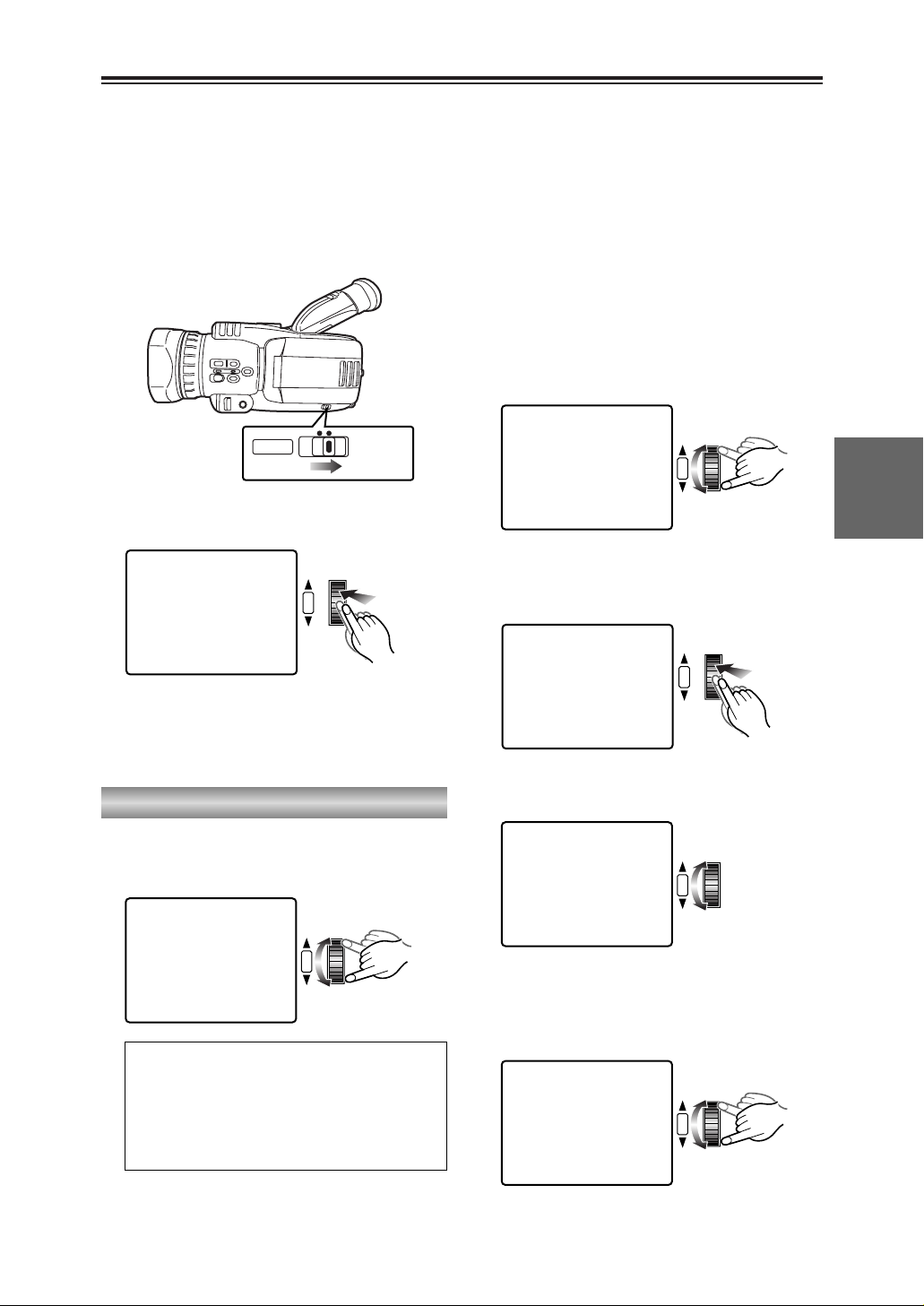
43
SHOOTING
Shutter speed, iris and gain adjustments
You can adjust the shutter speed, iris and gain
to suit the scenes being shot and the lighting
conditions.
Shutter speed adjustment
1
Set the AUTO/MANUAL selector switch to
MANUAL.
O No adjustments can be performed with
this switch at AUTO.
1
MANUALAUTO
2
Press the multi dial.
The shutter speed is displayed on the
screen.
1
1/60
SHUTTER/IRIS
VOL/JOG
PUSH
Slow shutter speeds:
1/4, 1/8, 1/15, 1/30
Regular shutter speeds:
1/60, 1/100-1/4000, 1/8000
Synchro scan shutter speeds:
1/60.3-1/250
1
1/120
SHUTTER/IRIS
VOL/JOG
PUSH
3
Turn the multi dial to select the shutter
speed.
1
SLOW
SHUTTER/IRIS
VOL/JOG
PUSH
Adjusting the slow shutter speed
You cannot switch to the slow shutter speed
while you are shooting at a normal shutter
speed.
Neither can you switch to the normal shutter
speed while you are shooting at a slow shutter
speed.
To make the switch, first set the camerarecorder to the shooting pause mode, and
then select the normal shutter speed or slow
shutter speed you desire.
1 Turn the multi dial in the direction for
reducing the shutter speed until SLOW
appears on the screen.
1
NORM
SHUTTER/IRIS
VOL/JOG
PUSH
Returning to the normal shutter speed
4 Turn the multi dial in the direction for
increasing the shutter speed until NORM
appears on the screen.
1
1/30
SHUTTER/IRIS
VOL/JOG
PUSH
2 When the multi dial is pressed, the number
representing the slow shutter speed appears
on the screen.
1
1/15
SHUTTER/IRIS
VOL/JOG
PUSH
Page 44

44
Shutter speed, iris and gain adjustments (cont.)
Iris and gain adjustments
Iris (F-number):
CLOSE, F16-F1.7, OPEN
Gain value:
0 dB, 3 dB-15 dB, 18 dB
SHUTTER/IRIS
VOL/JOG
PUSH
1/120
1
F2.8
0dB
5
Turn the multi dial to select the F-number.
SHUTTER/IRIS
VOL/JOG
PUSH
1/120
OPEN
1
3dB
7
Turn the multi dial to select the gain value.
6
When OPEN is selected as the F-number,
1
moves to the gain value.
1/120
1
F5.6
0dB
SHUTTER/IRIS
VOL/JOG
PUSH
4
When you press the multi dial, the iris and
gain values are displayed on the screen.
O When “IRIS” has been selected as the
FOCUS RING item setting on the SW MODE
screen using the menus (P68-P71), you can
use the focus ring to adjust the iris and gain
but only when you are shooting in the auto
focus mode. (P76)
Synchro scan shutter speeds
A synchro scan shutter speed is a shutter
speed used to shoot TV screens or PC
monitor screens.
The synchro scan shutter speed is set using
the SYNCHRO SCAN item on the CAMERA
SETUP screen when the synchro scan
shutter speed has been selected by the multi
dial. (P73)
O If you adjust the shutter speed to match the
frequency of the TV screen or PC monitor
screen, you can shoot the screen while
minimizing the horizontal noise that is
generated when TV screens are shot.
O With artificial lighting and especially fluorescent
lights and mercury-vapor lamps, the luminance
changes in synchronization with the power line
frequency. In areas where this frequency is 50
Hz, mutual interference will occur between the
camera-recorder’s vertical sync frequency
(approx. 60 Hz) and the lighting frequency (50
Hz). This means that the white balance may
change periodically.
Before shooting in areas with a 50 Hz frequency
or adjusting the white balance, set the shutter
speed to 1/100.
O The higher the shutter speed, the lower the
camera’s sensitivity.
O If the shutter speed is increased when the auto
iris is set (when the F-number is not displayed),
the iris will open (the F-number is reduced) so
that the background is more blurred and the
subject stands out.
O Shooting at a slow shutter speed may give rise
to such problems as after-image, a deterioration
in the image quality and difficulties in focusing.
O When a slow shutter speed has been selected,
images are shot with the CCD taking more time
than usual to accumulate the signals.
As a result, very small brilliant points that are
not usually visible may be recorded as the
images: this is normal and does not indicate an
error or malfunctioning.
1
1/60
SHUTTER/IRIS
VOL/JOG
PUSH
5 When the multi dial is pressed, the number
representing the normal shutter speed
appears on the screen.
Page 45

If you press the USER button to which the AWB
LOCK function has been allocated (P75) when
you are shooting in the auto white balance
mode, the white balance at the time the button
was pressed is used until the button is pressed
again.
Each time the button is pressed, the camerarecorder switches between auto white balance
and AWB lock.
45
SHOOTING
White balance adjustments
When you shoot with the AUTO/MANUAL
selector switch at the AUTO position, the white
balance is adjusted automatically while scenes
are being recorded.
As the white balance sensor is used to detect
the light source during shooting so the camerarecorder can adjust the white balance, do not
cover the sensor with your hand or anything
else.
Select the white balance setting mode if the
white balance needs to be adjusted very
precisely.
O Before shooting in areas with a 50 Hz power
line frequency or adjusting the white balance,
set the shutter speed to 1/100.
Setting the white balance
Auto white balance
White balance sensor
1
Set the AUTO/MANUAL selector switch to
MANUAL.
O No adjustments can be performed with
this switch at AUTO.
1
MANUALAUTO
2
Press the WHITE BAL button to select the
desired white balance setting mode.
Setting mode
W. LOCK: Lock mode
The current white balance is retained.
: Indoor (incandescent bulb) mode
Incandescent bulbs, halogen lamps
: Outdoor mode
Outdoors under clear skies
: Set mode
O Mercury-vapor lamps, sodium-vapor
lamps, some fluorescent lamps
O Lights used for wedding receptions in
hotels, theater spotlights
O Sunset, sunrise, etc.
No display: Auto mode
The white balance setting mode cannot be
selected while digital zooming is performed
with “k160” selected as the D. ZOOM item
(P76) setting on the SW MODE screen.
Page 46
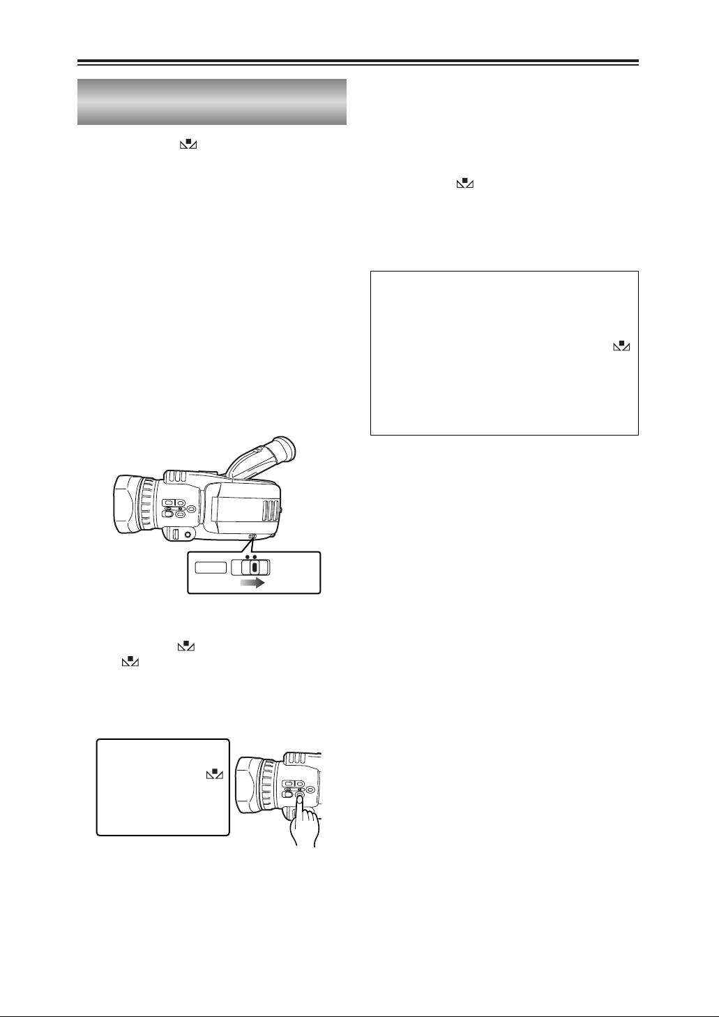
46
White balance adjustments (cont.)
3
Press the WHITE BAL button and hold it
down until the display lights.
The display will start to blink immediately
after it lights.
O This operation can be performed even if
the setting mode for the white balance
has been selected.
1
Place a white pattern in a location with the
same lighting conditions and light source as
the subject, then zoom in and fill the whole
screen with white.
A white object (a white cloth or white wall)
near the subject can be used instead of the
white pattern.
O Keep high-brightness spotlights and
yellow subjects off the screen.
4
The white balance is now adjusted
automatically.
The screen then darkens for a moment
before the black balance is adjusted
automatically.
When the adjustments have been
completed, stops blinking and changes
back to a lighted display.
O Do not move the screen away from the
subject until the adjustments are
completed.
2
Set the AUTO/MANUAL selector switch to
MANUAL.
O No adjustments can be performed with
this switch at AUTO.
1
MANUALAUTO
O If these steps are taken during shooting,
only the white balance will be adjusted.
O If the white balance cannot be adjusted
satisfactorily because the place is
extremely bright or extremely dark, the
display will blink slowly.
O The white balance cannot be adjusted
manually while digital zooming is performed
with “k160” selected as the D. ZOOM item
(P76) setting on the SW MODE screen.
In the set mode ( ), you can save the white
balance, which has been adjusted manually, in
the memory.
Adjusting the white balance manually
Page 47

2
Press the multi dial to move 1to MANUAL.
The MIC •A_IN LEVEL item is displayed.
The “∆” displayed below the level meter
indicates the standard level.
AUDIO LEVEL SETUPAUDIO LEVEL SETUP
PAUSE
MONITOR LEVEL
[–]
? ? ? ?
––––[+]
MICMIC•A_IN MODEA_IN MODE AUTO MANUAL AUTO MANUAL
MIC•A_IN LEVEL
[–]
? ? ? ? ? ? ? ? ? ? ? ? ? –––[+]
INPUT
(dB)
48K
PUSH MENU TO RETURNPUSH MENU TO RETURN
SHUTTER/IRIS
VOL/JOG
PUSH
CH1
-30 -10-20 -0
CH2
1
Hold down the MENU button until the AUDIO
LEVEL SETUP screen appears.
O In CAMERA mode, the screen selected
for the MIC •A_IN MODE item setting will
appear. On this screen, the mic input level
adjustment will take precedence.
In the VCR mode, the screen selected for
the MONITOR LEVEL item setting will
appear and the headphone and speaker
output level adjustments will take
precedence.
O On the AUDIO LEVEL SETUP screen, the
unit’s operation status is displayed at the
top right of the screen.
AUDIO LEVEL SETUPAUDIO LEVEL SETUP
PAUSE
MONITOR LEVEL
[–]
? ? ? ?
––––[+]
MICMIC•A_IN MODEA_IN MODE AUTO MANUAL AUTO MANUAL
INPUT
(dB)
48K
PUSH MENU TO RETURNPUSH MENU TO RETURN
MENU
CH1
-30 -10-20 -0
CH2
47
SHOOTING
Audio level adjustments
You can adjust the level of the audio input from
a microphone and the headphone volume to suit
the shooting conditions.
O You can use the same procedure as that for
“Adjusting the mic input audio level” to adjust
the audio input of the audio component
connected to the AV IN/OUT jack.
Adjusting the mic input audio level
3
Turn the multi dial to move to the MIC •A_IN
LEVEL item.
AUDIO LEVEL SETUPAUDIO LEVEL SETUP
PAUSE
MONITOR LEVEL
[–]
? ? ? ?
––––[+]
MIC•A_IN MODE MANUAL
MICMIC•A_IN LEVELA_IN LEVEL
[–]
? ? ? ? ? ? ? ? ? ? ? ? ? –––[+]
INPUT
(dB)
48K
PUSH MENU TO RETURNPUSH MENU TO RETURN
SHUTTER/IRIS
VOL/JOG
PUSH
CH1
-30 -10-20 -0
CH2
6
Press the multi dial to clear the “1” display
and complete the adjustment.
AUDIO LEVEL SETUPAUDIO LEVEL SETUP
PAUSE
MONITOR LEVEL
[–]
? ? ? ?
––––[+]
MIC•A_IN MODE MANUAL
MICMIC•A_IN LEVELA_IN LEVEL
[–]
? ? ? ? ? ? ? ?
–––––––[+]
INPUT
(dB)
48K
PUSH MENU TO RETURNPUSH MENU TO RETURN
PB.
ZOOM
MENU
SET
ITEM
PB.
ZOOM
MENU
SET
ITEM
PB.
ZOOM
MENU
SET
ITEM
PB.
ZOOM
MENU
SET
ITEM
Page 48

48
Audio level adjustments (cont.)
Adjusting the headphone volume
1
Hold down the MENU button until the AUDIO
LEVEL SETUP screen appears.
AUDIO LEVEL SETUPAUDIO LEVEL SETUP
PAUSE
MONITOR LEVEL
[–]
? ? ? ?
––––[+]
MICMIC•A_IN MODEA_IN MODE AUTO MANUAL AUTO MANUAL
INPUT
(dB)
48K
PUSH MENU TO RETURNPUSH MENU TO RETURN
MENU
CH1
-30 -10-20 -0
CH2
6
Press the MENU button to release the
AUDIO LEVEL SETUP screen.
MENU
3
Press the multi dial.
“1” appears to the left of the level meter
under the MONITOR LEVEL item.
AUDIO LEVEL SETUPAUDIO LEVEL SETUP
PAUSE
MONITOR LEVELMONITOR LEVEL
[–]
? ? ? ?
––––[+]
MIC•A_IN MODE AUTO
INPUT
(dB)
48K
PUSH MENU TO RETURNPUSH MENU TO RETURN
SHUTTER/IRIS
VOL/JOG
PUSH
PB.
ZOOM
MENU
SET
ITEM
SELECT
VAR.
PB.
SEARCH
STORE
OFF/ON
P.B.DIGITAL
PB.
ZOOM
MENU
SET
ITEM
ZOOM
MENU
SET
ITEM
Page 49

49
PLAYBACK
V
C
V
V
V
PLAY
/REW FF/
STILL ADV
PAUSE
INDEX
STOP INDEX
SELECT
STILL ADV
–
B
RESET
SEARCH
DIGITAL ZOOM
REC
BARS
MODE CHK ZEBRA OIS
MANUALAUTO
SEARCH
PHOTO SHOT
C
PLAY
/REW FF/
STILL ADV
PAUSE
INDEX
STOP INDEX
SELECT
C
PLAY
/REW FF/
STILL ADV
PAUSE
INDEX
STOP INDEX
SELECT
C
PLAY
/REW FF/
STILL ADV
PAUSE
INDEX
STOP INDEX
SELECT
STILL ADV
STILL ADV
STILL ADV
–
B
–
B
–
B
Page 50

50
Normal playback (cont.)
You can adjust the speaker volume when a tape
is being played back.
The adjustment will be reflected in the
headphone volume.
1
Hold down the multi dial until the audio level
meter is displayed.
VOLUMEVOLUME [–]
? ? ? ?
––––[+]
SHUTTER/IRIS
VOL/JOG
PUSH
2
Turn the multi dial to adjust the volume.
VOLUMEVOLUME [–]
? ? ? ? ? ? ?
––[+]
SHUTTER/IRIS
VOL/JOG
PUSH
3
Press the multi dial to clear the level meter
display.
SHUTTER/IRIS
VOL/JOG
PUSH
Adjusting the volume
When the camera-recorder is connected to a TV
set using the accessory AV cable or S-video
cord (option), you can view the playback images
on the TV screen.
1
Connect the camera-recorder to the TV set.
(P56)
2
Start playback.
O Press the OSD button on the remote
control unit to display the information
(counter, mode displays) appearing on the
LCD monitor and viewfinder on the TV
screen.
The displays are cleared when the OSD
button is pressed again.
Connecting a TV to view images
You can display the shooting date and time on
the screen by pressing the DATE/TIME button
on the remote control unit while a tape is playing
back.
Each time the button is pressed, the display
changes in the following sequence.
Time
7
Date
7
Time and date
7
Original screen
Checking the shooting date and time
TITLE
ZOOM
A.DUB
– VOL +
B
FF/
START/
DATE/
PHOTO
STOP
TIME
SHOT
OSD
COUNTER
RESET TITLE
REC A.DUB
ZOOM
OL +
MULTI/
P-IN-P
OSD
COUNTER
MULTI/
P-IN-P
DATE/
PHOTO
TIME
SHOT
RESET TITLE
REC A.DUB
START/
STOP
ZOOM
OL +
Page 51

51
PLAYBACK
Variable-speed playback
You can play back tapes recorded in the SP and
LP mode at about one-fifth and one-third of the
normal tape speed, respectively.
1
Play back the tape.
2
Press one of the STILL ADV (Dor E)
buttons on the remote control unit.
O Press the 1button to return to normal
playback.
O Press the 1button or ;button to return to
normal playback.
O Press the 1button to return to normal
playback.
V
Slow playback
MULTI/
If you press the ;button while the tape is
playing back, the camera-recorder is set to the
playback pause mode so that the still pictures of
the frames can be viewed.
Still-picture playback
MULTI/
Frame-feed playback can be initiated by turning
the multi dial during still-picture playback. Turn
the multi dial upward to play back the tape in the
forward direction and downward to play it back
in the reverse direction.
Frame-feed playback
SHUTTER/IRIS
VOL/JOG
PUSH
V
O Press the 1button to return to normal
playback.
The tape is cued by pressing the
5
button
while the tape is playing back and reviewed by
pressing the 6button.
The tape is cued or reviewed only for as long as
the button is held down.
Cue and review
MULTI/
REC A.DUB
RESET
SEARCH
REC
COUNTER RESET MODE CHK ZEBRA OIS
DIGITAL ZOOM
BARS
MANUALAUTO
SEARCH
PHOTO SHOT
P-IN-P
C
/REW FF/
PLAY
STILL ADV
PAUSE
INDEX
STOP INDEX
SELECT
– VOL +
B
STILL ADV
VAR.
PB.
STILL ADV
–
B
C
PLAY
/REW FF/
STILL ADV
PAUSE
INDEX
STOP INDEX
SELECT
REC A.DUB
RESET
SEARCH
DIGITAL ZOOM
REC
COUNTER RESET MODE CHK ZEBRA OIS
BARS
PHOTO SHOT
SEARCH
P-IN-P
C
/REW FF/
PLAY
STILL ADV
PAUSE
INDEX
STOP INDEX
SELECT
VAR.
STILL ADV
– VOL +
B
PB.
PLAY
STILL ADV
–
B
C
/REW FF/
STILL ADV
PAUSE
INDEX
STOP INDEX
SELECT
REC A.DUB
RESET
SEARCH
REC
COUNTER RESET MODE CHK ZEBRA OIS
DIGITAL ZOOM
BARS
MANUALAUTO
SEARCH
PHOTO SHOT
P-IN-P
C
/REW FF/
PLAY
STILL ADV
PAUSE
INDEX
STOP INDEX
SELECT
VAR.
STILL ADV
B
– VOL +
PB.
MANUALAUTO
Page 52

52
Search functions
O Press the 1button to return to normal
playback.
This function enables you to change the
playback speed and search for specific scenes.
Variable-speed search
1
Press the 1button on the camera-recorder
or the VAR SEARCH button on the remote
control unit while the tape is playing back.
“1k” appears on the viewfinder and LCD
monitor, and the tape is played back at the
normal speed.
No sound is heard at this time.
2
Turn the multi dial.
When the multi dial is turned, the playback
speed changes in the sequence of 1/5k (or
1/3k in the LP mode), 1k, 2k, 5k, 10k and
20k the normal tape speed.
The tape is played back in the forward
direction when the dial is turned upward and
in the reverse direction when it is turned
downward.
SHUTTER/IRIS
VOL/JOG
PUSH
Blank search
If, in the VCR mode, you press the USER button
(P75) to which you have allocated the BLANK
SEARCH function, the end of the last scene
shot (a blank part of the tape) is found, and a
still picture of the frame that is about a second
ahead of the end of the last scene is displayed.
O If there are no unrecorded blanks, the tape
will stop at the end of the tape.
O If shooting is started immediately after an
unrecorded blank has been found, the scene
will be recorded with frame-to-frame
continuity following on from the last frame.
USER2 button
USER3 button
USER1 button
INDEX
INDEX
SELECT
STORE
OFF/ON
P.B.DIGITAL
SELECT
STORE
OFF/ON
P.B.DIGITAL
STOP INDEX
VAR.
SEARCH
STOP INDEX
VAR.
SEARCH
MENU
MENU
PB.
ZOOM
SET
ITEM
PB.
ZOOM
SET
ITEM
RESET
SEARCH
REC
COUNTER RESET MODE CHK ZEBRA OIS
DIGITAL ZOOM
BARS
MANUALAUTO
SEARCH
PHOTO SHOT
Page 53

53
PLAYBACK
Search functions (cont.)
O To stop the search at any time, press the
STOP button ($).
This function searches for the index signals
recorded on the tape so that the tape can be
cued up to a particular part.
Index searches can only be performed using the
remote control unit.
Index search
Index signals
This camera-recorder can record index
signals that serve as a guide for tape cue-up.
O Photo index:
These signals are recorded when a tape
has been recorded using the photo shot
technique. (P39)
O Scene index:
These signals are recorded when index
recording has been performed. (P41, P75)
1
Using the menus (P68-P71), select the index
to be searched at the SEARCH item on the
PLAYBACK FUNCTION screen.
PLAYBACK FUNCTIONSPLAYBACK FUNCTIONS
SEARCHSEARCH PHOTO SCENE PHOTO SCENE
32K(12bit) AUDIO
ST1
AUDIO OUT CH1
•
CH2
PUSH MENU TO RETURNPUSH MENU TO RETURN
SHUTTER/IRIS
VOL/JOG
PUSH
2
Press one of the INDEX buttons (
9
or
:
) on the remote control unit.
+
P-IN-P
REC A.DUB
PHOTO:
When the INDEX button is pressed, the
tape is cued back or forward to the image
containing the photo index signal.
When the tape is cued, it is played back for
about 4 seconds, and then the image is
played back as a still picture. (If you
continue still-picture playback for 5 or more
minutes, the camera-recorder is set to the
stop mode in order to safeguard the heads
from wear.)
SCENE:
When the INDEX button is pressed once,
“S1” is displayed, and the tape is cued back
or forward to the image containing the photo
index signal.
Each time this button is pressed again after
operation has started, “S2” and then “S3”
are displayed, and the tape is cued up to
the second and subsequent scenes. When
the tape is cued up, playback starts from
that section. (Up to the ninth scene before
or ahead on the tape can be specified for
cue-up.)
The function may not work properly if the
interval between one index and the next is
less than one minute.
PB.
ZOOM
MENU
SET
ITEM
C
PLAY
/REW FF/
STILL ADV
PAUSE
INDEX
STOP INDEX
SELECT
VAR.
STILL ADV
– VOL
B
PB.
Page 54

When adding sound to an existing recording
by audio dubbing, you can use this function to
set the point at which the audio dubbing is to
end. (P59)
54
1
Press the COUNTER button to display the
counter memory.
2
At the desired position on the tape, press the
RESET button (counter) to reset the counter
memory display.
3
Proceed with playback or shooting.
5
When the tape is rewound or fast forwarded,
it stops automatically near where the counter
memory display was reset.
Counter
You can display a counter that indicates how
much time has elapsed during shooting or
playback by pressing the COUNTER button.
The following data is selected in turn each time
the COUNTER button is pressed.
0 : 00. 0 : Counter value
7
M 0 : 00. 0 : Counter memory
7
TC XX : XX : XX. XX : Time code
7
UB XX XX XX XX : User’s bit
7
Returns to original screen
O What is shown on the counter can be reset to
zero by pressing the RESET button (counter)
while the counter value or counter memory is
displayed.
O The time code and user’s bit cannot be reset
using the RESET button (counter).
Page 55

55
EDITING
PHONES
DV
CAM REMOTE
PHONES
DV
CAM REMOTE
DV cable (option)
4-pin type
Connecting external units
(P48)
Headphones
(P42, P61)
Digital video equipment
OBefore proceeding to connect or disconnect the DV cable (IEEE1394), be
absolutely sure to turn off the power of the units that are to be connected or
disconnected using this cable.
OBefore proceeding to connect the unit which uses a 6-pin type of DV
connector, carefully check the shape of the connectors on the DV cable and
unit. Connecting a connector upside down may damage the parts inside the
camera-recorder and cause malfunctioning.
Always connect the DV cable to the unit with the 6-pin type DV connector first.
OWhen recording signals from an external unit, first check that video signals are supplied.
OWhile signals from an external unit are being recorded, do not operate the external unit or disconnect any of
its cables. This will stop the output, which may result in the signals not being recognized when recording is
resumed.
OYou can connect a digital video unit equipped with a DV connector and digitally transfer video and audio
signals as well as time codes and other information.
OWhen a DV cable has been connected to the DV connector, do not apply any strong external force as this
may damage the connector.
6-pin type 4-pin type
Page 56

56
S-VIDEO
IN/OUT
MIC
AV
IN/OUT
XLR ADAPTER
S-VIDEO
IN/OUT
MIC
AV
IN/OUT
XLR ADAPTER
Connecting external units (cont.)
AV cable
(accessory)
AV cable
(accessory)
S-video cable (option)
Red: CH2 (R ch) audio
White: CH1 (L ch) audio
Yellow: Video
Yellow
Red: CH2 (R ch) audio
White: CH1 (L ch) audio
S-video connector
supported
(P58-P61)
TV set
S-video cable (option)
Red: CH2 (R ch) audio
White: CH1 (L ch) audio
Yellow: Video
Yellow
Red: CH2 (R ch) audio
White: CH1 (L ch) audio
S-video connector
supported
(P58-P61)
Video deck
OWhen connecting an external unit to the camera-recorder and inputting the video and audio signals of that
unit to the camera-recorder, connect the camera-recorder to the output connectors on the external unit.
OWhen connecting an external unit to the camera-recorder and outputting the video and audio signals of the
camera-recorder to that unit, connect the camera-recorder to the input connectors on the external unit.
OWhen video signals are input to both the S-VIDEO IN/OUT connector and AV IN/OUT jack, the signals of the
S-VIDEO IN/OUT connector take precedence.
OExcept when performing audio dubbing on existing recordings, audio signals cannot be recorded unless
video signals are input to the S-VIDEO IN/OUT connector and/or AV IN/OUT jack.
Page 57

57
EDITING
S-VIDEO
IN/OUT
MIC
AV
IN/OUT
XLR ADAPTER
S-VIDEO
IN/OUT
MIC
AV
IN/OUT
XLR ADAPTER
XLR microphone
(AG-MC100G, option)
Stereo microphone
(AG-MC15, option)
XLR microphone adapter
(AG-MYA30G, option)
Connecting external units (cont.)
(P58, P59)
External microphone
(connected to phono jack)
(P58, P59)
External microphone (connected to XLR connector)
Page 58

7
When the PAUSE button (;) on the remote
control unit is pressed, the camera-recorder
reurns to the still-picture playback mode.
If more sound is to be dubbed, repeat steps
5 and 6.
8
When the STOP button ($) on the remote
control unit is pressed, audio dubbing is
stopped.
58
When the AUDIO DUB (sound adding)
function is allocated to a USER button on the
camera-recorder, audio dubbing can be
performed (sound can be added) by operating
that button in the same way as the PAUSE
button (;) on the remote control unit.
Audio dubbing
3
Select the sound to be recorded using the A
DUB INPUT item on the AV IN/OUT SETUP
screen. (P78)
2
Using the menus (P68-P71), select the audio
recording system at the AUDIO REC item on
the RECORDING SETUP screen. (P76)
Background music or narration can be added to
the images you have recorded on the tape.
(P56, P57)
1
Turn the POWER lever to set the camerarecorder to the VCR mode.
1
O
F
F
O
N
M
O
D
E
POWER
CAMERA
VCR
MIC:
The sound of the built-in or external microphone is
recorded.
A_IN:
The sound of the audio component connected to the
AV IN/OUT jack is recorded.
32K (12bit):
The sound is recorded using the 12-bit/32kHz (4channel) system.
Use this mode when you want to keep the sound that
was heard while you were shooting even after audio
dubbing has been performed.
48K (16bit):
The sound is recorded using the 16-bit/48kHz system
(2 channels with a good sound quality).
When audio dubbing is performed, the sound that was
heard while you were shooting will be erased.
4
Find the scene where the sound is to be
added, and set the camera-recorder to the
still-picture playback mode. (P51)
? ?
5
Press the A.DUB button on the remote
control unit to establish the status ready for
audio dubbing.
A.DUB A.DUB
? ?
6
Press the PAUSE button (;) on the remote
control unit and start input of the sound to be
dubbed.
A.DUB A.DUB
1
USER2 button
USER3 button
USER1 button
RESET
SEARCH
DIGITAL ZOOM
REC
BARS
COUNTER RESET MODE CHK ZEBRA OIS
SEARCH
PHOTO SHOT
C
PLAY
/REW FF/
STILL ADV
PAUSE
STILL ADV
INDEX–STOP INDEX
B
COUNTER
RESET TITLE
REC A.DUB
PLAYC/REW FF/
ZOOM
– VOL +
B
MULTI/
P-IN-P
B
PLAYC/REW FF/
STILL ADV
PAUSE
STILL ADV
INDEX–STOP INDEX
MANUALAUTO
Page 59

59
EDITING
Audio dubbing (cont.)
$ Listening to sound that has
been dubbed
You can switch between the sound that has
been dubbed and the sound heard during
shooting using the 32K (12bit) AUDIO item
setting on the PLAYBACK FUNCTION
screen. (P74)
ST1:
The sound heard during shooting is played
back.
ST2:
The sound that has been dubbed on a
recording is played back.
MIX:
Both the sound heard during shooting and
that you have dubbed on a recording are
played back at the same time.
$ Performing audio dubbing as
you listen to it
You can monitor the sound by setting “ST2”
while audio dubbing is temporarily
suspended.
If you use headphones when performing
audio dubbing on a recording using mic
input, you can listen to the sound being
dubbed.
When you perform audio dubbing using line
input (from the audio component connected
to the AV IN/OUT jack), you can listen to the
sound being dubbed through the speakers.
$ Using the counter memory
function to edit dubbed sound
1 First reset the counter memory display at
the position where the audio dubbing is to
end. (P54)
2 Rewind the tape to the position where the
audio dubbing is to start, and start the
dubbing.
3 The tape then stops automatically at the
position on the tape where the counter
memory display was reset.
$ Adjusting the audio input level
Use the procedure described for “Adjusting
the mic input audio level” (P47) to adjust the
audio level of mic input and line input (from
the audio component connected to the AV
IN/OUT jack).
$ Adjusting the audio output
level
Use the procedure described for “Adjusting
the headphone volume” (P48) to adjust the
audio level output from the headphones and
speakers.
Inputs and audio tracks for recordings
2 You will need the XLR microphone adapter (AG-
MYA30G, option) if you intend to use the XLR
microphone. (P57)
O Which sound is to be recorded during shooting is
automatically determined by the order of priority for the
mic inputs.
O The audio tracks on which dubbed sound is to be
recorded can be changed using the A.DUB INPUT item
on the AV IN/OUT SETUP screen. (P78)
Input
When performing audio dubbing
in the 32K (12bit) mode
A. DUB INPUT:
MIC
A. DUB INPUT:
A_IN
Order of priority
for mic inputs
High
Low
When shooting
External mic L channel CH1 CH3
__
External mic R channel CH2 CH4
__
INPUT 1 (XLR mic) 2
CH1 CH3
__
INPUT 2 (XLR mic) 2
CH2 (CH1) CH4 (CH3)
__
Internal mic L channel CH1 CH3
__
Internal mic R channel CH2 CH4
__
Audio IN/OUT CH1 (L channel)
(white phono jack)
__ __
CH3
Audio IN/OUT CH2 (R channel)
(red phono jack)
__ __
CH4
Page 60

60
Dubbing
2
Turn on the power of the external unit, and
play back the tape.
4
Press the $ button to stop the recording.
5
Stop play back on the external unit.
Using the dubbing function, you can dub (copy)
the contents of S-VHS (or VHS) cassettes onto
DV cassettes or record TV programs. (P56)
1
Turn the POWER lever to set the camerarecorder to the VCR mode.
1
O
F
F
O
N
M
O
D
E
POWER
CAMERA
VCR
Analog input
3
To start recording, press the REC button
while holding down the REC sub button on
the camera-recorder.
If you are using the remote control unit,
press the PLAY button while holding down
the REC button.
O If you do this during still-picture playback
(P51), the camera-recorder will be set to
the rec pause status.
To resume recording from the rec pause
status, press the ;button.
MULTI/
$ Adjusting the audio input level
Use the procedure described for “Adjusting
the mic input audio level” (P47) to adjust the
audio level of mic input and line input (from
the audio component connected to the AV
IN/OUT jack).
COUNTER
RESET TITLE
RESET
SEARCH
REC
COUNTER RESET MODE CHK ZEBRA OIS
DIGITAL ZOOM
BARS
MANUALAUTO
SEARCH
PHOTO SHOT
MULTI/
P-IN-P
STILL ADV
INDEX
REC A.DUB
PLAYC/REW FF/
PAUSE
STOP INDEX
STILL ADV
ZOOM
– VOL +
B
REC A.DUB
RESET
SEARCH
REC
COUNTER RESET MODE CHK ZEBRA OIS
DIGITAL ZOOM
BARS
MANUALAUTO
SEARCH
PHOTO SHOT
P-IN-P
C
/REW FF/
PLAY
STILL ADV
PAUSE
INDEX
STOP INDEX
SELECT
VAR.
STILL ADV
– VOL +
B
PB.
Page 61
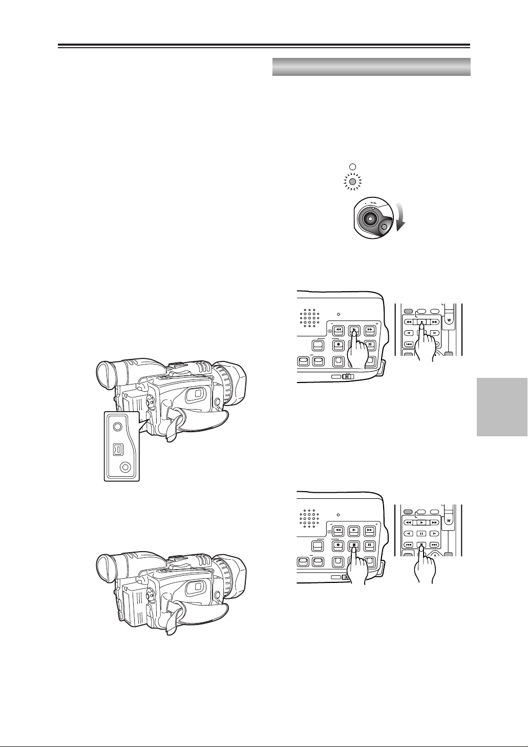
61
EDITING
Dubbing (cont.)
You can use a video deck to dub the images
you have shot using this camera-recorder onto
an S-VHS (or VHS) cassette tape. (P56)
Analog output
2
Press the 1 button to play back the tape in
the camera-recorder.
5
Press the $ button to stop playing back the
tape in the camera-recorder.
1
Turn the POWER lever to set the camerarecorder to the VCR mode.
1
O
F
F
O
N
M
O
D
E
POWER
CAMERA
VCR
3
Start recording on the video deck.
4
Stop recording on the video deck.
MULTI/
MULTI/
PHONES
DV
CAM REMOTE
REC A.DUB
RESET
SEARCH
REC
COUNTER RESET MODE CHK ZEBRA OIS
DIGITAL ZOOM
BARS
SEARCH
PHOTO SHOT
P-IN-P
C
/REW FF/
PLAY
STILL ADV
PAUSE
INDEX
STOP INDEX
SELECT
VAR.
STILL ADV
– VOL +
B
PB.
MANUALAUTO
REC A.DUB
RESET
SEARCH
REC
COUNTER RESET MODE CHK ZEBRA OIS
DIGITAL ZOOM
BARS
MANUALAUTO
SEARCH
PHOTO SHOT
P-IN-P
C
/REW FF/
PLAY
STILL ADV
PAUSE
INDEX
STOP INDEX
SELECT
VAR.
STILL ADV
– VOL +
B
PB.
Page 62

62
Dubbing (cont.)
5
Press the $ button to stop playback in the
player.
4
Press the $ button to stop the recording in
the recorder.
MULTI/
MULTI/
You can perform dubbing with a high image
quality by means of digital signals by using the
DV cable (option) to connect the camerarecorder to a digital video unit equipped with a
DV connector (IEEE 1394 connector). (P55)
Digital input/output
2
Press the 1 button to play back the tape in
the player.
1
Turn the POWER lever to set the player unit
and recorder unit to the VCR mode.
1
O
F
F
O
N
M
O
D
E
POWER
CAMERA
VCR
MULTI/
3
To start recording in the recorder, press the
REC button while holding down the REC sub
button.
If you are using the remote control unit,
press the PLAY button while holding down
the REC button.
O If you do this during still-picture playback
(P51), the camera-recorder will be set to
the rec pause status.
To resume recording from the rec pause
status, press the ;button.
O Digitally dubbed sound is recorded in the
same audio mode as the player’s tape
regardless of the recorder’s menu setting.
O When dubbing is performed with “ON”
selected as the 1394 TC REGEN and 1394
UB REGEN item settings on the recorder’s
menu, the player’s time code and user’s bit
can be copied. (P76, P77)
In this case, check the recorder’s screen to
verify that the player’s images are being
received before starting to record.
If you start recording when there are no
images being received from the recorder, it
may not be possible to copy the time code
and user’s bit properly.
REC A.DUB
RESET
SEARCH
REC
COUNTER RESET MODE CHK ZEBRA OIS
DIGITAL ZOOM
BARS
MANUALAUTO
SEARCH
PHOTO SHOT
P-IN-P
C
/REW FF/
PLAY
STILL ADV
PAUSE
INDEX
STOP INDEX
SELECT
– VOL +
B
STILL ADV
VAR.
PB.
COUNTER
RESET TITLE
RESET
SEARCH
REC
COUNTER RESET MODE CHK ZEBRA OIS
DIGITAL ZOOM
BARS
SEARCH
PHOTO SHOT
MULTI/
P-IN-P
STILL ADV
INDEX
REC A.DUB
PLAYC/REW FF/
PAUSE
STOP INDEX
STILL ADV
ZOOM
– VOL +
B
REC A.DUB
RESET
SEARCH
REC
COUNTER RESET MODE CHK ZEBRA OIS
DIGITAL ZOOM
BARS
MANUALAUTO
SEARCH
PHOTO SHOT
P-IN-P
C
/REW FF/
PLAY
STILL ADV
PAUSE
INDEX
STOP INDEX
SELECT
– VOL +
B
STILL ADV
VAR.
PB.
REC A.DUB
RESET
SEARCH
REC
COUNTER RESET MODE CHK ZEBRA OIS
DIGITAL ZOOM
BARS
MANUALAUTO
SEARCH
PHOTO SHOT
P-IN-P
C
/REW FF/
PLAY
STILL ADV
PAUSE
INDEX
STOP INDEX
SELECT
– VOL +
B
STILL ADV
VAR.
PB.
MANUALAUTO
Page 63

63
DISPLAYS
Screen displays
Displays in CAMERA and VCR modes
1. Warning information
REMOTE:
This blinks when the wrong equipment
setting has been selected on the remote
control unit. (P25)
:
This blinks when condensation has
formed inside the camera-recorder. (P84)
:
This blinks when the cylinder heads are
dirty.
:
This blinks when the cassette tape has
not been inserted or the one that has
been inserted is set to the recording
inhibited status.
END:
This blinks when the tape has come to its
end.
:
This blinks if a problem has occurred in
the camera-recorder while taking a selfportrait in the mirror mode.
:
This blinks when the internal battery for
the calendar has run out. (P30)
2. Back-up unit modes
The status (modes) of the backup unit
connected to the DV connector is displayed
here.
No status is displayed when “OFF” has
been selected as the DV CONTROL item
setting on the OTHER FUNCTIONS screen.
(P79)
DV ¥ :Recording
DV
;
: Recording standby
: The backup unit cannot be
controlled.
DV : The backup unit has not been
connected.
DV – – :The backup unit is connected but it
is not in the recording or recording
standby mode.
3. Recording time mode
SP :SP (standard play) mode
LP : LP (long play) mode
4. Squeeze information
This display appears when recording with
“SQUEEZE” selected as the ASPECT
CONV item setting on the CAMERA SETUP
screen or when images recorded in the
squeeze mode are played back. (P40, P73)
5. Setting selection
The selected setting is displayed here when
a switch is selected or a button is pressed
to select a setting.
2
PAUSE D16X Z0 0
DVO
TC 12:34:56.00 1.25X
SP MNL
SQU MOVI E–L I KE MF
U1 : PUSH AF+ZM
1/
100
U2 : BACL I GHT F5 . 6
U3 : AE LOCK 18
dB
99 S SN:IR SNS
WINDCUT
INDEX
RNOV30200323:59:59
48
KM
222min
CH1
CH2
1
2
3
4
5
7
9
10
11
19
20
21
22
23
24
=
=
=
=
25
26
18
17
32 31 29 2830
1412 1513
16
8
6
27
Items with the = mark next to their numbers in
the figure at left are also displayed in the VCR
mode as camera data when “ON” has been
selected as the CAMERA DATA item setting on
the DISPLAY SETUP screen. (P78)
Page 64

64
Displays in CAMERA and VCR modes
Screen displays (cont.)
6. Button functions
The functions allocated to the USER
buttons (P75) and high-sensitivity shooting
mode (P37) are displayed here while the
MODE CHK button is held down.
7. Video level
The video level near the markers is
displayed here. (P39)
8. Markers
The markers are displayed here when the
ZEBRA button is pressed twice during
shooting. (P39)
9. Wind noise reduction
WIND CUT is displayed here when “ON”
has been selected as the WIND CUT item
setting on the RECORDING SETUP
screen. (P38, P76)
10. Time stamp
is displayed here when “REC” has been
selected as the TIME STAMP item setting
on the RECORDING SETUP screen. The
date and time are recorded as part of the
images on the tape. (P37, P76)
11. Audio recording system
The digital sound recording system is
displayed here. (P76)
12. Mic manual mode
“M” is displayed here when sound is
recorded manually using the internal
microphone or external microphone. (P47)
13. Audio level meter
This indicates the levels of the audio input
and output signals.
14. Remaining tape
The remaining tape time is displayed here.
It is not displayed while it is being
calculated or during slow playback.
15. Remaining battery charge
As the remaining battery charge drops, the
display changes as follows:
5
555
.
When the battery has completely
discharged, ( ) blinks. (When
the AC adapter is being used, a display
other than may appear: this is not a
sign of malfunctioning.)
R
16. Calendar
The current date and time are displayed
here.
When the BARS button is pressed to
display color bars, the ID information set at
the ID SET item on the DISPLAY SETUP
screen is displayed.
17. Index recording
“INDEX” lights during index signal
recording. This is initiated by pressing the
USER button in which the INDEX function
has already been allocated during
recording. (P41, P75)
It blinks when the INDEX button is pressed
before recording (to indicate the index
signal recording standby status).
18. High-sensitivity shooting mode
SNS is displayed here when shooting in a
high-sensitivity mode. (P37)
19. Gain value
The gain value used for shooting is
displayed here. (P44)
20. F-number
The iris (F-number) used for shooting is
displayed here. (P44)
“” appears when the backlight is being
compensated. (P41)
“” appears in the spotlight mode. (P75)
mmm dd yyyy hh:mm:ss
Month:
JAN (January), FEB (February), MAR (March), APR
(April), MAY (May), JUN (June), JUL (July), AUG
(August), SEP (September), OCT (October), NOV
(November), DEC (December)
Day of the month
Year:
2000 --- 2089
Hours: (24-hour clock)
Minutes
Seconds
Page 65

65
DISPLAYS
21. Shutter speed
The shutter speed used for shooting is
displayed here. (P43)
22. White balance information
The white balance information is displayed
here. (P45, P46)
23. Manual focus control
“MF” is displayed here when the focus is
controlled manually. (P42)
24. Vibration reduction ( )
“” is displayed here when the vibration
reduction function is used. (P38)
25. Digital zoom
This display appears when the digital zoom
function is used. (P36)
26. Zoom position
The zoom position from Z00 (max. wide
angle) to Z99 (max. telephoto) is displayed
here.
27. Operation control
The operation control mode of the camerarecorder is displayed here.
No display : Auto mode
MNL : Manual mode
: This is displayed while the AE
lock function is working. (P41)
28. Zoom value
The zoom value is displayed here for
several seconds when it has been changed.
“D” appears when the digital zoom function
is being used.
29. Operation mode displays
REC : Recording
¥ : Recording (for self-portraits)
PAUSE : Recording standby
¥
;
: Recording standby
(for self-portraits)
;;
: Playback pause
STNDBY : Standby
(cylinder heads stopped)
A.DUB
;;
: Audio dubbing standby
A/DUB
11
: Audio dubbing
11
: Playback
55(66
):Fast forward/cue (rewind/review)
??11(22 ??
):Slow playback (slow playback in
reverse direction)
AE LOCK
CHK : Rec check
99(::
): Cue-up (cue-up in reverse
direction)
;; 11(22 ;;
): Frame feed playback (frame
feed playback in reverse
direction)
BLANK : Blank search
k
11/k55(k22/k66
):
Variable-speed search (variable-speed
search in reverse direction)
30. One-shot recording
An asterisk (2) appears when the camerarecorder has been set up for frame feed
recording. It blinks in the shooting pause
mode. (P40)
31. Counter
The following data is selected in turn each
time the COUNTER button is pressed.
0 : 00. 0:
Counter value
M 0 : 00. 0:
Counter value in counter memory mode
TC XX : XX : XX. XX:
Time code value. “TC2” appears when
this value cannot be read correctly from
the tape.
UB XX XX XX XX:
User’s bit value. “UB2” appears when
this value cannot be read correctly from
the tape.
32. Filename used
The name of the scene file used for the
current shooting is displayed here. (P73)
Screen displays (cont.)
Displays in CAMERA and VCR modes
Page 66

66
33. Monitor volume level meter
Press the multi dial to display the level
meter showing the volume level of the
sound that is output from the internal
speaker and PHONES jack.
34. Search number
The index number used to perform the
index search is displayed here. (S1 to S9)
Screen displays (cont.)
In VCR mode only
The following messages are displayed in the
center of the screen when a problem with the
camera-recorder, tape, etc. has occurred.
UNPLAYABLE TAPE (OTHER FORMAT)
The tape cannot be played back because it is
in the wrong format.
COPY INHIBITED
The material cannot be recorded properly
because its input signals are copy-guarded.
UNABLE TO A. DUB (LP RECORDED)
Audio dubbing cannot be performed on this
tape since it was recorded in the LP mode.
INCOMPATIBLE TAPE
This tape cannot be used because it
conforms to a different standard (data saving
tape, etc.).
EXTERNAL DV DISCONNECT
This message appears when shooting with
“EXT” selected as the DV CONTROL item
setting on the OTHER FUNCTIONS screen
and with no external unit connected to the
DV connector. (P42, P55, P79)
FOCUS LOCK
This message appears when a problem has
occurred during focusing.
ZOOM LOCK
This message appears when a problem has
occurred during zooming.
PSD NG
This message appears when a problem has
occurred with the vibration detection function.
AUTO OFF
AUTO OFF is displayed when a problem has
occurred with the tape transport system.
When it appears, the camera-recorder’s
power is automatically turned off.
CYLINDER LOCK
LOADING LOCK
LOW BATTERY
S REEL LOCK
(supply reel lock)
T REEL LOCK
(take-up reel lock)
UNLOADING LOCK
Warnings
PAUSE S 1
TC 12:34:56.00
SP
SQU
F5. 6
18
dB
WINDCUT
NOV 30 2 0
03
23:59:59
48
KM
222min
CH1
CH2
VOLUME –
??????
–– +
33
34
Page 67

67
DISPLAYS
Screen displays (cont.)
Using the MODE CHK button
Z00
TC 12 : 34 :56 .00 1.25X
SP MNL
SQU MOV I E– LIKE MF
U1: PUSH AF+ZM
1/
100
U2:BACLIGHT F5.6
U3 : AE LOCK 18
dB
SSN : I R SNS
WINDCUT
RNOV30200323:59:59
48
KM
222min
CH1
CH2
Setting the DISPLAY items
D16X Z00
1.2 5 X
MF
1/
100
F5. 6
18
dB
RNOV30200323:59:59
M
222 min
The amount of information to be displayed can
be set by using the menus (P68-P71) to select
the DISPLAY item setting on the DISPLAY
SETUP screen. (P78)
When “PARTIAL” is selected as the
DISPLAY item setting
D16X Z00
1.2 5 X
SP MNL
SQU MF
1/
100
F5. 6
18
dB
SNS
WINDCUT
RNOV30200323:59:59
48
KM
222min
When “ALL” is selected as the DISPLAY
item setting
Page 68

68
Menu operations
Using menus, you can change the camera-recorder’s settings to suit the scenes to be shot or
material to be recorded.
O You cannot perform menu operations while you are shooting or recording.
Setting the menu mode
1
Press the MENU button.
The main items now appear on the screen.
O The camera menu appears in the
CAMERA mode; the VCR menu appears
in the VCR mode.
SHUTTER/IRIS
VOL/JOG
PUSH
MENU
OSD
COUNTER
RESET TITLE
STILL ADV
PAUSE
STILL ADV
INDEX
SELECT
STORE
OFF/ON
P.B.DIGITAL
VAR.
SEARCH
– VOL +
PB.
ZOOM
MENU
SET
ITEM
STOP INDEX
MULTI/
P-IN-P
REC A.DUB
PLAY
C
/REW FF/
B
ZOOM
DATE/
TIME
PHOTO
SHOT
START/
STOP
[CAMERA mode]
[VCR mode]
O When the remote
control unit is used
CAMERA MENUCAMERA MENU
1.SCENE FILE 1.SCENE FILE
2.CAMER SETUP
3.SW MODE
4.RECORDING SETUP
5.DISPLAY SETUP
6.OTHER FUNCTIONS
PUSH MENU TO EXITPUSH MENU TO EXIT
VCR MENUVCR MENU
1.PLAYBACK FUNCTIONS 1.PLAYBACK FUNCTIONS
2.SW MODE
3.RECORDING SETUP
4.AV IN/OUT SETUP
5.DISPLAY SETUP
6.OTHER FUNCTIONS
PUSH MENU TO EXITPUSH MENU TO EXIT
Page 69

69
MENUS
Selecting the sub items
Menu operations (cont.)
4
Turn the multi dial.
The highlighting moves to the next sub item
in turn.
SHUTTER/IRIS
VOL/JOG
PUSH
Example:
OTHER FUNCTIONSOTHER FUNCTIONS
REMOTE VCR1
DV CONTROLDV CONTROL OFF EXT OFF EXT
BOTH CHAIN BOTH CHAIN
DV CMD SEL REC P
REC LAMP OFF
BEEP SOUND OFF
CLOCK SET ––––
PUSH MENU TO RETURNPUSH MENU TO RETURN
Selecting the main items
2
Turn the multi dial.
The highlighting moves to the next main item
in turn.
SHUTTER/IRIS
VOL/JOG
PUSH
3
Press the multi dial at the position of the item
to be displayed.
The sub items are now displayed.
SHUTTER/IRIS
VOL/JOG
PUSH
Example:
CAMERA MENUCAMERA MENU
1.SCENE FILE
2.CAMER SETUP
3.SW MODE
4.RECORDING SETUP
5.DISPLAY SETUP
6.OTHER FUNCTIONS 6.OTHER FUNCTIONS
PUSH MENU TO EXITPUSH MENU TO EXIT
Example:
OTHER FUNCTIONSOTHER FUNCTIONS
REMOTEREMOTE VCR1 VCR2 VCR1 VCR2
OFF OFF
DV CONTROL OFF
DV CMD SEL REC P
REC LAMP OFF
BEEP SOUND OFF
CLOCK SET ––––
PUSH MENU TO RETURNPUSH MENU TO RETURN
SELECT
VAR.
PB.
SEARCH
STORE
OFF/ON
P.B.DIGITAL
ZOOM
MENU
SET
ITEM
SELECT
VAR.
PB.
SEARCH
STORE
OFF/ON
P.B.DIGITAL
ZOOM
MENU
SET
ITEM
SELECT
STORE
OFF/ON
P.B.DIGITAL
VAR.
SEARCH
PB.
ZOOM
MENU
SET
ITEM
Page 70

70
Menu operations (cont.)
Entering the settings
For items whose setting is to be selected
5
Press the multi dial at the position of the item
to be changed, and move 1to the desired
setting.
The setting is now changed.
SHUTTER/IRIS
VOL/JOG
PUSH
Example:
OTHER FUNCTIONSOTHER FUNCTIONS
REMOTE VCR1
DV CONTROLDV CONTROL OFF EXT OFF EXT
BOTH CHAIN BOTH CHAIN
DV CMD SEL REC P
REC LAMP OFF
BEEP SOUND OFF
CLOCK SET ––––
PUSH MENU TO RETURNPUSH MENU TO RETURN
For items whose numerical value setting
is to be changed
5
Press the multi dial at the position of the item
to be changed, then press the dial again and
move 1to the position of the numerical
value which is to be changed.
O Turn the multi dial, and change the
setting.
SELECT
VAR.
PB.
SEARCH
STORE
OFF/ON
P.B.DIGITAL
ZOOM
MENU
SET
ITEM
Page 71

71
MENUS
Menu operations (cont.)
Setting other sub items
6
To set another sub item, repeat steps 4 and 5.
Setting other main items
8
To set another main item, repeat steps 2 to 5.
Returning to the main item screen
7
Press the MENU button.
MENU
Releasing the menu mode
9
Press the MENU button again.
MENU
Example:
CAMERA MENUCAMERA MENU
1.SCENE FILE
2.CAMER SETUP
3.SW MODE
4.RECORDING SETUP
5.DISPLAY SETUP
6.OTHER FUNCTIONS 6.OTHER FUNCTIONS
PUSH MENU TO EXITPUSH MENU TO EXIT
Initializing the menu settings
O When “INITIAL” is selected as the USER FILE item setting on the OTHER FUNCTIONS screen,
you can return the menu settings in the currently used user file to their factory settings. (P80)
O If “INITIAL” is selected as the SAVE/INT item setting on the SCENE FILE screen while you are
using a scene file (in the SETTING item on the SCENE FILE screen), you can return the menu
settings in that scene file to their factory settings. (P73)
SELECT
VAR.
PB.
SEARCH
STORE
OFF/ON
P.B.DIGITAL
ZOOM
MENU
SET
ITEM
SELECT
VAR.
PB.
SEARCH
STORE
OFF/ON
P.B.DIGITAL
ZOOM
MENU
SET
ITEM
Page 72

RECORDING SETUP REC SPEED
AUDIO REC
WIND CUT
TCG
FIRST REC TC
TC PRESET
1394 UB REGEN
1394 TC REGEN
UB PRESET
UB MODE
OTHER FUNCTIONS
REMOTE
CLOCK SET
TIME SHIFT
USER FILE
HOUR METER
PLAYBACK FUNCTIONS
SEARCH
32K (12bit) AUDIO
AUDIO OUT
SW MODE
USER1
USER2
USER3
AV IN/OUT SETUP
A. DUB INPUT
DV OUT
DISPLAY SETUP
VIDEO OUT OSD
DATE/TIME
LEVEL METER
DISPLAY
CAMERA DATA
LCD BACKLIGHT
LCD/EVF SET
EVF MODE
EVF COLOR
EVF DETAIL
VCR MENU
(P74)
(P76)
(P76)
(P78)
(P78)
(P79)
VCR mode menu
72
CAMERA MENU
SCENE FILE
CAMERA SETUP
SCENE FILE
SETTING
NAME EDIT
SAVE/INIT
RECORDING SETUP
REC SPEED
AUDIO REC
WIND CUT
ID SET
TIME STAMP
TCG
FIRST REC TC
TC PRESET
UB MODE
UB PRESET
ONE-SHOT REC
REC TIME
OTHER FUNCTIONS
REMOTE
DV CONTROL
DV CMD SEL
REC LAMP
BEEP SOUND
CLOCK SET
TIME SHIFT
TAPE PROTECT
IR LED
USER FILE
HOUR METER
SYNCRO SCAN
ASPECT CONV
SETUP
SW MODE
USER1
USER2
USER3
FOCUS RING
IRIS DIAL
ZOOM MODE
FRONT S/S INHIBIT
SNS
D. ZOOM
DISPLAY SETUP
ZEBRA DETECT
VIDEO OUT OSD
LEVEL METER
DISPLAY
LCD BACKLIGHT
LCD/EVF SET
DATE/TIME
SELF SHOOT
EVF MODE
EVF COLOR
EVF DETAIL
DETAIL LEVEL
CHROMA LEVEL
CHROMA PHASE
COLOR TEMP
MASTER PED
AE SHIFT
SKIN TONE DTL
REC MODE
Menu configuration
CAMERA mode menu
(P73)
(P73)
(P75)
(P76)
(P78)
(P79)
Page 73

73
MENUS
Menu configuration (cont.)
Item/
(Display
mode)
Description of settings
SCENE FILE
(CAMERA)
Settings corresponding to four shooting
conditions are saved as scene files in this
camera-recorder. Use this item to select the
scene file to be used.
1. SCENE1:
The settings of various menu items were
stored in this file at the factory.
2. SCENE2:
The settings of various menu items were
stored in this file at the factory.
3. B.PRESS:
This file is useful for shooting dark areas
with a sharper contrast.
4. MOVIE-LIKE:
This file is useful for shooting movie-like
images.
<Note>
You can change the settings in the scene
files using the SETTING item.
SETTING
(CAMERA)
Use this to change the settings in the scene
files.
DETAIL LEVEL:
–7 --- 0 --- +7
Set this level in the “–” direction to soften
the image outlines.
When it is set in the “+” direction, the
image outlines are emphasized and
sharp images are produced, but the
amount of noise is increased slightly.
CHROMA LEVEL:
–7 --- 0 --- +7
Set this level in the “–” direction to make
the image colors lighter.
Set it in the “+” direction to make them
darker.
CHROMA PHASE:
–7 --- 0 --- +7
Use this to adjust the hue.
COLOR TEMP:
–7 --- 0 --- +7
Set this in the “–” direction to make the
images more reddish overall.
Set it in the “+” direction to make the
images more bluish overall.
MASTER PED:
–15 --- 0 --- +15
Set this in the “–” direction to make the
images darker overall. When a setting
below –5 is selected, the dark parts of
the images may become blackened out.
When it is set in the “+” direction, the
dark parts of the images (such as the
shadows) become brighter.
AE SHIFT:
–4 --- 0 --- +4
Use this to adjust the auto iris setting.
Set it in the “–” direction for a darker
setting.
Set it the “+” direction for a brighter
setting.
SKIN TONE DTL:
OFF
, ON
When ON is selected, soft skin tones are
reproduced when people are shot,
making them look more attractive.
REC MODE:
NORM
Shooting is performed using field
recording (60 fields per second).
FRAME
Shooting is performed using frame
recording (30 frames per second).
High-quality images can be obtained at
this setting when playing back still
images, for example.
NAME EDIT
(CAMERA)
Use this to edit the name of the selected
scene file.
SAVE/INIT
(CAMERA)
SAVE:
The changed settings in the scene file
(one of the files listed in the file selection
item) are saved.
The original scene file settings will be
restored when the menu mode is
released, the operation is switched to the
VCR mode or when the power is turned
off if SAVE has not been selected.
INITIAL:
The selected scene file settings are
returned to the factory settings.
The underlining indicates the factory setting.
SCENE FILE screen
SYNCRO
SCAN
(CAMERA)
Use this to adjust the synchro scan shutter
speed used for shooting images on a TV
screen, etc. (P43, P44)
1/60.3 --- 1/250
ASPECT
CONV
(CAMERA)
Use this to select the aspect ratio of the
images which are to be recorded. (P40)
NORMAL, LETTER BOX, SQUEEZE
SETUP
(CAMERA)
Use this to add the setup level (black level).
0%
:
The setup level is not added.
7.5%:
A 7.5% setup level is added for
recording.
CAMERA SETUP screen
Item/
(Display
mode)
Description of settings
Item/
(Display
mode)
Description of settings
Page 74

74
The underlining indicates the factory setting.
Menu configuration (cont.)
SEARCH
(VCR)
Use this to set the operation to be
performed when an INDEX button (9or
:
) on the remote control unit is pressed.
PHOTO:
A photo search is conducted. (P53)
SCENE:
An index search is conducted. (P53)
32K (12bit)
AUDIO
(VCR)
Use this to set the sound to be output as
CH1 and CH2 signals when playing back a
tape that was recorded in the 32K (12-bit)
audio mode.
ST1:
This selects the sound that was recorded
during shooting.
CH1 signals = CH1 track
CH2 signals = CH2 track
ST2:
This selects the sound that was dubbed
on the recording.
CH1 signals = CH3 track
CH2 signals = CH4 track
MIX:
This mixes the sound that was recorded
during shooting and the sound that was
dubbed on the recording.
CH1 signals = CH1 + CH3 tracks
CH2 signals = CH2 + CH4 tracks
<Note>
When sound is recorded in the 48K (16-bit)
audio mode, CH3 and CH4 do not exist so
the following always stands:
CH1 signals = CH1 track
CH2 signals = CH2 track
AUDIO OUT
(VCR)
Use this to set the audio signals to be
output from the AV IN/OUT jack when the
tape is played back.
CH1•CH2:
CH1 output = CH1 signals
CH2 output = CH2 signals
CH1:
CH1 output = CH1 signals
CH2 output = CH1 signals
CH2:
CH1 output = CH2 signals
CH2 output = CH2 signals
32K (12bit) AUDIO item/AUDIO OUT item settings and audio track signals output from
the AV IN/OUT jack
Audio recording
mode
AUDIO OUT
item setting
AV IN/OUT jack
CH1 output
AV IN/OUT jack
CH2 output
32K (12bit) AUDIO
item setting
32K (12-bit)
48K (16-bit)
CH1•CH2
CH1
CH2
CH1
CH1
CH2
CH2
CH1
CH2
ST1
CH1•CH2
CH1
CH2
CH3
CH3
CH4
CH4
CH3
CH4
ST2
__
CH1+CH3 CH2+CH4MIX
CH1•CH2
CH1
CH2
CH1
CH1
CH2
CH2
CH1
CH2
__
PLAYBACK FUNCTION screen
Item/
(Display
mode)
Description of settings
Item/
(Display
mode)
Description of settings
Page 75

75
MENUS
USER1
(CAMERA)
(VCR)
This enables one function to be allocated to
the USER1 button.
$ Camera menu mode
(PUSH) AF+ZOOM:
Select this to execute one-touch
zooming. (P41)
(PUSH) AF:
Select this to switch to auto focus mode
when the camera-recorder is operated in
the manual focus mode but only while
the button is held down.
WHITE BAL:
This works in the same way as the
WHITE BAL button when the white
balance is to be set. (P45, P46)
AWB LOCK:
Select this to enable operations to be
performed with the white balance that
was in effect when the button was
pressed while operating the camerarecorder in the auto white balance mode.
(P45)
BACKLIGHT:
Select this to set the backlight
compensation function to ON or OFF.
(P41)
SPOTLIGHT:
Select this to set the auto iris control for
the spotlight to ON or OFF.
REC CHECK:
Select this to perform a rec check. (P14)
D. ZOOM:
Select this to perform digital zooming.
(P36)
WHITEFADE:
Select this to fade out the whole image
in white while the button is held down
during shooting. At the same time, the
sound is also faded out.
Conversely, fade-in in white occurs when
the button is released. At the same time,
the sound is also faded in.
BLACKFADE:
Select this to fade out the whole image
in black when the button is held down
during shooting. At the same time, the
sound is also faded out.
Conversely, fade-in in black occurs when
the button is released. At the same time,
the sound is also faded in.
PHOTO SHOT:
Select this for photo shot recording.
(P39)
INDEX:
Select this for index recording. (P41)
SNS:
Select this to set the camera-recorder to
the high-sensitivity shooting mode. (P37)
SW MODE screen
EVF DTL:
Select this to emphasize the outlines of
the images on the screen when the
button is pressed so that the subject
becomes easier to bring into focus. “EVF
DTL ON” appears for about 2 seconds in
the center of the screen after the button
has been pressed. However, the regular
images are what is recorded, not the
ones with their outlines emphasized.
The original images are restored by
pressing the button again. “EVF DTL
OFF” appears for about 2 seconds in the
center of the screen.
LUMI-FLICK:
Select this to make the screen flicker so
that images which will give the
impression that reels of photographic
film are turning just as they did years
ago are recorded.
AE LOCK:
Select this to set the camera-recorder to
the AE lock mode. (P41)
$ VCR menu mode
BLANK SEARCH:
Select this to conduct a blank search.
(P52)
AUDIO DUB:
This works in the same way as the
A.DUB button on the remote control unit
when performing audio dubbing. (P58)
INDEX:
Select this for index recording. (P41)
USER2
(CAMERA)
(VCR)
This enables one function to be allocated to
the USER2 button.
For further details, refer to the USER1 item.
$ Camera menu mode
(PUSH) AF+ZOOM, (PUSH) AF, AWB LOCK,
BACKLIGHT
, SPOTLIGHT, REC CHECK,
D. ZOOM, WHITEFADE, BLACKFADE,
PHOTO SHOT, INDEX, EVF DTL, LUMI-FLICK,
AE LOCK
$ VCR menu mode
BLANK SEARCH, AUDIO DUB, INDEX
USER3
(CAMERA)
(VCR)
This enables one function to be allocated to
the USER3 button.
For further details, refer to the USER1 item.
$ Camera menu mode
(PUSH) AF+ZOOM, (PUSH) AF, AWB LOCK,
BACKLIGHT, SPOTLIGHT, REC CHECK,
D. ZOOM, WHITEFADE, BLACKFADE,
PHOTO SHOT, INDEX, EVF DTL, LUMI-FLICK,
AE LOCK
$ VCR menu mode
BLANK SEARCH, AUDIO DUB, INDEX
Menu configuration (cont.)
The underlining indicates the factory setting.
Item/
(Display
mode)
Description of settings
Item/
(Display
mode)
Description of settings
Page 76

76
The underlining indicates the factory setting.
REC SPEED
(CAMERA)
(VCR)
Use this to select the recording duration
mode.
SP:
SP (standard recording) mode.
LP:
LP (long recording) mode.
AUDIO REC
(CAMERA)
(VCR)
Use this to select the digital audio recording
system.
32K (12bit):
The sound is recorded using the 12-bit/
32 kHz (4 channels) recording system.
Select this mode when leaving the sound
heard during shooting intact even when
audio dubbing is performed on an
existing recording.
48K (16bit):
The sound is recorded using the 16-bit/
48 kHz (2 channels with a good sound
quality) recording system.
The sound heard during shooting will be
erased when dubbing over an existing
recoding.
WIND CUT
(CAMERA)
(VCR)
Select ON to reduce the noise generated
by the wind blowing into the microphone in
windy conditions.
OFF, ON
1394 TC
REGEN
(VCR)
Use this to select the time code to be
recorded when recording the signals of the
unit connected to the DV connector.
OFF:
The time code that was selected using
the TCG setting item and FIRST REC
TC setting item is used for the recording.
ON:
The time code of the signals which are
input to the DV connector are used for
the recording.
O When ON has been selected for this
item, the time code of the signals
concerned takes precedence over the
TCG item and FIRST REC TC item
settings.
O If no signals are input to the DV
connector, the TCG item and FIRST
REC TC item settings are used.
ID SET
(CAMERA)
Use this to set the ID (5 characters)
information. The ID information set is
displayed when the color bar mode is
established.
O Characters which can be set:
) (space), A to Z, 0 to 9, :, ., /
TIME STAMP
(CAMERA)
Set this to REC to record the date and time
that were selected using the DATE/TIME
setting item (P78) on the DISPLAY SETUP
screen as an image on the tape.
NO-REC, REC
Menu configuration (cont.)
FOCUS RING
(CAMERA)
Use this to select the function to be
allocated to the focus ring.
ZOOM:
Zooming can be performed using the
focus ring when the camera-recorder is
operated in the auto focus mode.
IRIS:
Iris adjustments can be performed using
the focus ring when the camera-recorder
is operated in the auto focus mode and
the iris is to be adjusted manually.
OFF:
The focus ring is used to perform manual
focus adjustments only.
IRIS DIAL
(CAMERA)
Use this to set how the iris is to be
controlled by the direction in which the multi
dial is rotated when the iris is to be adjusted
manually.
DOWN OPEN:
The iris opens when the multi dial is
turned downward.
UP OPEN:
The iris opens when the multi dial is
turned upward.
ZOOM MODE
(CAMERA)
Use this to set the speed of the motordriven lens zoom. (P36)
NORM:
Standard
HIGH :
High speed
LOW :
Low speed
FRONT S/S
INHIBIT
(CAMERA)
Use this to set whether the recording
operation is to be performed using the
START/STOP button on the lens.
OFF:
Recording is permitted.
ON:
Recording is inhibited so as to prevent
operation from being conducted by
mistake.
SNS
(CAMERA)
Use this to select the high-sensitivity
shooting mode. (P37)
IR, SUPER_IR, COLOR_NS
SW MODE screen RECORDING SETUP screen
D. ZOOM
(CAMERA)
Use this to select the magnification level for
the digital zoom. (P36)
x24, x160
Item/
(Display
mode)
Description of settings
Item/
(Display
mode)
Description of settings
Page 77

77
MENUS
Menu configuration (cont.)
TCG
(CAMERA)
(VCR)
Use this to set the mode in which to
advance the time code.
FREE RUN:
The time code is advanced continuously
regardless of the operation mode.
It is recorded on the basis of the time
appearing on the camera-recorder’s
calendar clock.
REC RUN:
The time code is advanced only when
recording is underway.
It is recorded while ensuring that
continuity is maintained with the time
code already recorded on the tape when
shooting with frame-to-frame continuity.
FIRST REC TC
(CAMERA)
(VCR)
Use this to select the time code to be
recorded when recording is started.
REGEN:
Select this to record the time code that
will ensure continuity with the time code
already on the tape.
The time code is recorded in the REC
RUN mode regardless of the setting
selected for the TCG item.
PRESET:
Select this to record the time code using
the value selected by the TC PRESET
item as the initial value.
However, when shooting with frame-toframe continuity has taken place, the
time code is recorded to ensure
continuity with the time code already on
the tape.
TC PRESET
(CAMERA)
(VCR)
Use this to set the initial value of the time
code to be recorded.
The item takes effect when “PRESET” has
been selected as the FIRST REC TC item
setting.
1394 UB
REGEN
(VCR)
Use this to select the user’s bit to be
recorded when recording the signals of the
unit connected to the DV connector.
OFF:
The user’s bit selected by the UB MODE
item is recorded.
ON:
The user’s bit of the signals input to the
DV connector is recorded.
O When “ON” has been selected as this
item’s setting, it takes precedence over
the UB MODE item setting.
O If the signals do not contain the user’s bit
information, the user’s bit is not
recorded.
O If no signals are input to the DV
connector, the UB MODE item setting is
used for the recording.
The underlining indicates the factory setting.
RECORDING SETUP screen
REC TIME
(CAMERA)
Use this to set the recording time for frameby-frame shooting.
0.5s :
0.5 sec.
1s :
1.0 sec.
1.5s :
1.5 sec.
2s :
2.0 sec.
ONE-SHOT
REC
(CAMERA)
Use the ON setting when shooting on a
frame-by-frame basis.
OFF:
Frame-by-frame shooting is not
performed.
ON:
The camera-recorder is set to the frameby-frame shooting mode.
When the START/STOP button is
pressed, recording proceeds for the
number of seconds selected by the REC
TIME item setting, and then the camerarecorder is set to the REC PAUSE
mode.
UB MODE
(CAMERA)
(VCR)
Use this to set what is to be recorded as
the user’s bit.
USER:
The user’s information is recorded.
TIME:
The recording time is recorded.
DATE:
The recording date is recorded.
TCG:
The time code is recorded.
UB PRESET
(CAMERA)
(VCR)
Use this to set the user’s bit.
For this, however, “USER” must have been
selected as the UB MODE item setting.
Item/
(Display
mode)
Description of settings
Item/
(Display
mode)
Description of settings
Page 78

78
ZEBRA
DETECT
(CAMERA)
Use this to set the brightness level at which
the zebra patterns are to be displayed.
80%, 85%, 90%, 95%, 100%, 105%
VIDEO OUT
OSD
(CAMERA)
(VCR)
Select the ON setting to output the
information displayed on the screen
together with the signals from the AV
IN/OUT jack.
ON, OFF
DATE/TIME
(CAMERA)
(VCR)
Use this to set whether to display the date
and/or time on the screen and on the
signals that are output from the AV IN/OUT
jack.
OFF:
The date and time are not displayed.
TIME:
The time is displayed.
DATE:
The date is displayed.
TIME&DATE:
The date and time are displayed.
O If any setting other than OFF is selected,
the time and/or date are displayed for
the signals that are output from the AV
IN/OUT jack, regardless of the setting
selected for the VIDEO OUT OSD item.
LEVEL METER
(CAMERA)
(VCR)
Select ON to display the audio level meter
on the screen.
OFF, ON
DISPLAY
(CAMERA)
(VCR)
Use this to set the amount of information to
be displayed on the screen. (P67)
OFF, PARTIAL
, ALL
LCD
BACKLIGHT
(CAMERA)
(VCR)
Use this to adjust the backlight of the LCD
monitor.
When HI is selected, the backlight is made
brighter than usual.
HI, NORMAL
DISPLAY SETUP screen
CAMERA
DATA
(VCR)
With the ON setting, the camera settings
(vibration reduction, F-number, gain value
and white balance information) at the time
of shooting are displayed when the tape is
played back.
OFF, ON
<Note>
When a tape on which the unit’s camera
settings has been recorded is played back
on another unit, the camera settings may
not be displayed properly.
Menu configuration (cont.)
The underlining indicates the factory setting.
A. DUB INPUT
(VCR)
Use this to select the sound to be recorded
when performing audio dubbing.
MIC:
The sound of the internal microphone or
external microphone is recorded. (P58)
A_IN:
The sound of the audio unit connected to
the AV IN/OUT jack is recorded.
<Note>
If audio dubbing is performed on a
recording which was made in the 48K (16bit) audio mode, the sound heard during
shooting will be overwritten and the dubbed
sound recorded in its place.
DV OUT
(VCR)
Select the ON setting when converting
analog input signals into digital signals and
outputting them from the DV connector.
OFF, ON
AV IN/OUT SETUP screen
Item/
(Display
mode)
Description of settings
Item/
(Display
mode)
Description of settings
Page 79

79
MENUS
Menu configuration (cont.)
LCD/EVF SET
(CAMERA)
(VCR)
Use this to adjust the display level of the
images appearing in the viewfinder or on
the LCD monitor.
LCD BRIGHTNESS:
Select this to adjust the brightness of the
images on the LCD monitor.
LCD COLOR LEVEL:
Select this to adjust the color level of the
images on the LCD monitor.
EVF BRIGHTNESS:
Select this to adjust the brightness of the
images in the viewfinder.
SELF SHOOT
(CAMERA)
When MIRROR is selected, an image with
the left and right sides reversed will appear
on the LCD monitor when shooting a selfportrait.
NORMAL, MIRROR
EVF MODE
(CAMERA)
(VCR)
Use this to select to switch the screen
images.
ON:
The images are always displayed in the
viewfinder.
AUTO:
The images in the viewfinder are cleared
when the LCD monitor is opened.
EVF COLOR
(CAMERA)
(VCR)
Select ON to display the images on the
viewfinder screen in color.
OFF:
The images are displayed in black and
white.
ON:
The images are displayed in color.
EVF DETAIL
(CAMERA)
(VCR)
When ON is selected, the contours of the
images in the viewfinder and on the LCD
monitor are emphasized to make focusing
easier.
However, the images recorded will be
normal images without emphasized
contours.
OFF, ON
The underlining indicates the factory setting.
DISPLAY SETUP screen OTHER FUNCTIONS screen
REMOTE
(CAMERA)
(VCR)
Use this to set the operations to be
performed using the accessory remote
control unit. (P25)
VCR1:
Operations performed using the remote
control unit which has been set up for
use with VCR1 are accepted.
VCR2:
Operations performed using the remote
control unit which has been set up for
use with VCR2 are accepted.
OFF:
No operations performed using a remote
control unit are accepted.
DV CONTROL
(CAMERA)
Use this to set the control method to be
used when a backup unit is connected to
the DV connector and backup recording is
to be performed.
OFF:
The backup unit is not controlled.
EXT:
The backup unit is controlled using the
camera-recorder’s START/STOP button.
The images shot using the camerarecorder are recorded using the backup
unit. (The camera-recorder does not
perform the recording operation.)
BOTH:
The images shot using the camerarecorder are recorded by both the
camera-recorder and the backup unit.
CHAIN:
When the camera-recorder’s tape
approaches its end during shooting,
recording is automatically started by the
backup unit that has been waiting in the
recording standby mode.
DV CMD SEL
(CAMERA)
Use this to set the recording operation to be
performed by the backup unit when the
camera-recorder’s START/STOP button is
pressed.
REC_P:
The START/STOP button switches
between recording and rec pause.
STOP:
The START/STOP button switches
between recording and stop.
<Note>
If the backup unit does not have a rec
pause function, select STOP.
REC LAMP
(CAMERA)
Select ON to light the tally lamp during
shooting. (P84)
OFF, ON
Item/
(Display
mode)
Description of settings
Item/
(Display
mode)
Description of settings
Page 80

80
HOUR METER
(CAMERA)
(VCR)
Use this to display the total running time (a
5-digit figure in 1-hour increments) of the
cylinder head.
USER FILE
(CAMERA)
(VCR)
LOAD:
The menu (except scene file) settings
which were saved last are loaded.
SAVE:
The changed menu settings are saved.
INITIAL:
The menu settings are returned to the
factory settings.
O When the power is turned off without
selecting SAVE, the VCR mode menu
settings will be saved but the CAMERA
mode menu settings will be returned to
the original settings.
O When a LOAD or INITIAL operation has
been performed, set the camerarecorder’s POWER lever first to the OFF
position and then back to ON in order to
ensure that the settings concerned will
take effect.
Menu configuration (cont.)
BEEP SOUND
(CAMERA)
Select ON to be warned by a beep that the
shooting has started or ended or that a
problem has occurred.
OFF, ON
The beeps are output as audio signals from
the PHONES jack and AV IN/OUT jack.
When a beep is sounded, the audio signals
from the built-in microphone are muted and
the beep is output instead.
One beep sounds:
O when the POWER lever is set to the ON
position
O when shooting has started
Two beeps sound:
O when shooting is paused
10 beeps sound in succession:
O when a cassette tape has not been
inserted
O when the cassette tape is set to the
recording inhibited status
O when condensation has formed inside
the camera-recorder
O when a problem has occurred in the
camera-recorder
CLOCK SET
(CAMERA)
(VCR)
Use this to set the camera-recorder’s
internal calendar.
TIME SHIFT
(CAMERA)
(VCR)
The time set using this item is added to the
clock time of the internal calendar (time
difference compensation) and displayed on
the viewfinder and LCD monitor. The added
time is also recorded on the tape.
+23h --- +1h, OFF
, –1h --- –23h
(In 1-hour increments)
TAPE
PROTECT
(CAMERA)
When the camera-recorder has been left in
the pause mode for about 5 minutes, it is
automatically set to the tape protection
mode.
Use this item to select the kind of tape
protection mode to be established.
POWER OFF:
The camera-recorder’s power is set to
OFF.
STBY:
The cylinder head is set to the stop
status.
The underlining indicates the factory setting.
OTHER FUNCTIONS screen
IR LED
(CAMERA)
Use this to set the control over the infrared
light which is used during high-sensitivity
recording. (P37)
AUTO:
The infrared light comes on as soon as
the high-sensitivity shooting mode is
established.
OFF:
The infrared light does not come on no
matter whether the high-sensitivity
shooting mode is established or not.
Item/
(Display
mode)
Description of settings
Item/
(Display
mode)
Description of settings
Page 81

81
TROUBLE-
SHOOTING
Before calling for service
There’s no power.
O Have the battery and AC adapter been
connected properly?
Check the connections again. (P12, P24)
Power shuts off for no apparent reason.
O To prevent the battery from running down
needlessly and to safeguard the tape from
wear, the camera-recorder’s power is
automatically turned off when the camerarecorder has been left in the shooting pause
mode for more than 5 minutes.
Check the setting you have selected for the
TAPE PROTECT item on the OTHER
FUNCTIONS screen. (P80)
Power goes off as soon as it is turned on.
O Has the battery run out?
If the remaining battery charge display is
blinking or the display appears, it
means that the battery has run out.
Either recharge the battery or replace the
discharged battery with a fully charged one.
(P23)
O Has any condensation formed?
At times when, for instance, the camerarecorder is taken from a cold place to a
heated room, condensation may form inside.
If this happens, the power is automatically
turned off and the only operation that you will
be able to perform is to remove the cassette.
Wait until the condensation has dried out.
(P84)
Power supply
The battery runs down quickly.
O Has the battery been fully charged?
Keep charging it until the AC adapter’s
CHARGE lamp goes off. (P23)
O Are you using the battery in a cold place?
The battery is affected by the ambient
temperature. Its operating time is reduced in
low-temperature locations.
O Has the battery reached the end of its service
life?
The battery has a fixed service life which
differs depending on how the battery is used.
If the battery operates only for a short period
even when it is charged adequately, it means
that it has reached the end of its service life.
The battery cannot be charged.
O Is the DC cord connected to the AC adapter?
You cannot charge the battery if this cord is
connected.
Battery
I can’t record even though I’ve inserted the
cassette tape properly.
O Is the tab on the cassette tape used to
prevent accidental erasure at the open
(SAVE) position?
You cannot record if this tab is open. (P18)
O Has the cassette tape come to the very end?
If so, replace it with another one.
O Is the POWER lever at the ON position?
O Is the VCR lamp lighted?
You cannot shoot in the VCR mode.
O Has condensation formed?
If it has formed, the only operation you can
perform is to remove the cassette tape. Wait
until the condensation has dried out. (P84)
O Has the AUTO OFF or T REEL LOCK
warning display appeared?
Check the tape as it may have snapped.
O Is the external unit disconnected from the DV
connector while you are trying to perform
backup recording with “EXT” selected as the
DV CONTROL item setting on the OTHER
FUNCTIONS screen? (P79)
Normal video recording
Page 82

82
Before calling for service (cont.)
The subject is not brought into focus
automatically.
O Is the manual focus mode established?
You can focus automatically only when the
auto focus mode is established. (P35, P42)
O Are you shooting a scene where it’s hard to
bring the subject into focus in the auto focus
mode?
Some subjects are hard to bring into focus in
the auto focus mode. If this is the case, bring
the subject into focus in the manual focus
mode.
It may be hard to bring the subject into focus
when:
1. both close and distant objects are to be
shot
2. shooting through dirty windows or other
glass
3. shooting in dark places
4. there are sparkling or shiny objects around
the subject
5. subjects are moving fast
6. shooting scenes with minimal contrast
7. shooting at a low shutter speed
Other types of video recording
I can’t perform audio dubbing.
O Is the tab on the cassette tape used to
prevent accidental erasure at the open
(SAVE) position?
You cannot edit if this tab is open. (P18)
O Are you trying to edit a part that was shot in
the LP mode?
You cannot perform audio dubbing on tapes
recorded in the LP mode because the tracks
on the tape in this mode are narrower than
the head width.
Editing
There’s something wrong with the time code
display.
O If a tape is played in the reverse slow mode,
the time code display may not register a
regular count, but this is not a sign of
malfunctioning.
The remaining tape display differs from the
actual amount of tape remaining.
O The remaining tape is not displayed
accurately if you shoot continuously for
periods of less than 30 seconds.
O The display may show 2 to 3 minutes less
remaining tape than the time actually
remaining on the tape.
Displays
I can’t play back a tape even when I press
the play button.
O Is the VCR lamp lighted?
No kind of playback operation can be
performed unless this lamp is lighted. (P49)
Mosaic-like noise appears when I cue or
review a tape.
O This noise is inherent to digital video
technology. It is not a sign of malfunctioning.
Playback images do not appear on the TV
screen even though I have connected the
camera-recorder to the TV set properly.
O Is the TV input selector set to “video input?”
Read the TV set’s instruction manual
carefully, and select the video input
connector you should use to connect your
camera-recorder.
The playback images are not displayed
clearly.
O Are the camera-recorder’s heads dirty?
The playback images will not be displayed
clearly if these heads are dirty.
Playback (images)
Page 83

83
TROUBLE-
SHOOTING
Before calling for service (cont.)
I can’t hear any sound from the camerarecorder’s speaker.
O Have you turned down the camera-recorder’s
volume control too far?
In the VCR mode, adjust the volume level
using the multi dial. (P50)
I can hear two sets of sound.
O Have you selected “MIX” as the 32K (12bit)
AUDIO item setting on the PLAYBACK
FUNCTION screen? (P74)
O If you perform audio dubbing on a tape that
was recorded with “32K (12bit)” selected as
the AUDIO REC item setting on the
RECORDING SETUP screen, you will hear
the sound heard during recording and that of
the audio dubbing. (P76)
When I performed audio dubbing on an
existing recording, the original sound was
erased.
O If you perform audio dubbing on a tape that
was recorded with “48K (16bit)” selected as
the AUDIO REC item setting on the
RECORDING SETUP screen, you will erase
the original sound on the tape. To leave the
original sound intact, make sure that “32K
(12bit)” is selected as the item setting when
you shoot the original recording. (P76)
Playback (sound)
I can’t remove the cassette tape.
O Is power still being supplied to the camera-
recorder? (Is the power from the AC adapter
and battery supplied properly?)
So long as the power is supplied, you can
remove the cassette even if the POWER
lever is at the OFF position.
I can remove the cassette but I can’t perform
any other operations.
O Has condensation formed?
If it forms, the only operation you can perform
is to remove the cassette. Wait until the
condensation has dried out. (P84)
O If the cassette cover is closed immediately
after sliding the EJECT switch to open the
cassette cover, you may no longer be able to
perform any operations other than eject.
If you did this, slide the EJECT switch again
to open the cassette cover, check that the
cassette mechanism has finished ejecting the
cassette, and then close the cassette cover.
The remote control unit does not work.
O Has the button battery in the remote control
unit run out?
If the remote control fails to work even when
it is operated near the camera-recorder’s
remote control sensor, it means that the
button battery has run out. Replace it with a
new one. (P25)
O Is the remote control setting the same for the
remote control unit and the camera-recorder?
If the REMOTE item setting does not
correspond between the two units, the
remote control unit will not work. (P25, P79)
I hear a rattling sound when I tilt the camerarecorder back and forth.
O There are some parts in the structure of the
camera unit that make a rattling sound in the
VCR mode or when the POWER lever is at
the OFF position. This is not a sign that
something is broken.
Other
Page 84

Tally lamp
The tally lamp can be made to light up during shooting by
selecting “ON” as the REC LAMP item (P79) setting on the
OTHER FUNCTIONS screen.
When the camera-recorder is in any of the following
statuses, the tally lamp blinks.
O When the remaining charge of the battery is low
O When there is not much tape left
O When trouble has occurred in the tape transport system
O When an operation initiated by the remote control unit
has been received
O When the camera-recorder’s mode is being switched to
shooting
Tally lamp
84
Condensation
How to find out whether there is
condensation inside and what to do about it
if it has formed
If the condensation mark blinks after the
camera-recorder’s power has been turned on, it
means that condensation has formed inside the
camera-recorder. If this has happened, the
power is automatically turned off within a matter
of seconds.
Take the following action.
1 Remove the cassette
No other functions will be operational. It may
not even be possible to remove the cassette
tape depending on the amount of
condensation. If this is the case, wait two to
three hours before removing the cassette.
2 Wait two to three hours with the cassette
holder open.
The time you need to wait will differ
depending on the amount of condensation
and the ambient temperature.
3 Turn on the power two to three hours later
and check whether or not the
condensation display has gone off.
To make doubly sure, wait another hour or so
after the condensation display has gone off
before using the camera-recorder again.
Also remember that even when the
condensation display has not appeared,
condensation may be forming.
O Condensation builds up gradually so the
condensation display may not appear for 10
to 15 minutes after it has started to form
inside.
O In very cold areas, the condensation may
freeze. If this happens, it will take another
two to three hours for it to thaw out.
System resetting
Reset the system microcomputer if you can no longer
operate the camera-recorder even though its power is on or
a similar kind of a problem has occurred.
Use a pointed object to press the RESET button on the
camera-recorder. This will reset the system microcomputer.
The menu settings entered and memory contents will not be
cleared even when the system is reset.
Do not press the RESET button when the camerarecorder is operating normally.
SEARCH
RESET
SEARCH
DIGITAL ZOOM
REC
COUNTER RESET MODE CHK ZEBRA OIS
PHOTO SHOT
BARS
MANUALAUTO
RESET button
Page 85

Page 86

86
Specifications
indicates safety information.
Supply voltage: DC 7.2 V/7.9 V
Power consumption:
5.0 W (when the viewfinder is used)
6.1 W (when the LCD monitor is used)
Power consumption when XLR
microphone adapter (AG-MYA30G) is
connected:
6.2 W (when the viewfinder is used)
7.4 W (when the LCD monitor is used)
8.5 W (maximum)
[GENERAL]
Ambient operating temperature
32°F to 104°F (0°C to 40°C)
Ambient operating humidity
10% to 85% (no condensation)
Weight
2.31 lb (1.05 kg)
(excluding battery and accessories)
Dimensions (WkHkD)
4
3
/8k4 5/8k10 inches (110k116k253 mm)
The height increases to 6
5
/16 inches (160
mm) when the handle is attached.
Recording format
Digital video SD format
Tape format
Mini DV system
Video signals recorded
525i (NTSC)
Shooting mode
60i
Audio signals recorded
PCM digital recording
16 bits: 48 kHz/2 channels
12 bits: 32 kHz/4 channels
Recording tracks
Digital video/audio:
Helical tracks
Time code:
Helical track (sub code area)
Tape speeds
SP mode: 18.812 mm/sec.
LP mode: 12.555 mm/sec.
Recording time (when AY-DVM60 is used)
SP mode: 60 minutes
LP mode: 90 minutes
Tapes used
6.35 mm wide metal tapes
FF/REW time
Approx. 140 sec. (when AY-DVM60 is used)
Pickup devices
Interline transfer
1
/
4-inch CCD image senser
(k3)
Number of pixels
Total number of pixels: 410,000,
Number of effective pixels: 380,000
(pixel offset system)
Lens
Leica DICOMAR
optical image stabilizer lens
,
motorized 16k zoom,
F1.6 (f=4.1 to 65.6 mm)
(35 mm equivalent: 39.5 to 632 mm)
Color separation optical system
Prism system
ND filter
Interlocked with iris, auto ON/OFF
Gain settings
0, +3, +6, +9, +12, +15, +18 dB
Shutter speed settings
Slow shutter speeds:
1/4, 1/8, 1/15, 1/30 sec.
Regular shutter speeds:
1/60, 1/100, 1/120, 1/180, 1/250, 1/350,
1/500, 1/750, 1/1000, 1/1500, 1/2000,
1/3000, 1/4000, 1/8000 sec.
Synchro scan shutter speeds:
1/60.3 to 1/250 sec.
Minimum subject illuminance
4 lux:
F1.6, +18 dB gain, 50 IRE video output
Lens hood
Large-sized lens hood with wide angle of
view
Filter diameter
43 mm
LCD monitor
3.5-inch LCD color monitor, 200,000 pixels
Viewfinder
0.44-inch, LCD color viewfinder, 180,000
pixels
Internal microphone
Stereo microphone
Internal speaker
20 mm diameter
Page 87

87
SPECIFI-
CATIONS,
OTHER
Specifications (cont.)
[VIDEO]
Sampling frequency
Y: 13.5 MHz, PB/PR: 3.375 MHz
Quantizing
8 bits
Video compression system
DCT + variable-length code
Error correction
Reed-Solomon product code
[AUDIO]
Sampling frequency
48 kHz/32 kHz
Quantizing
16 bits/12 bits
Frequency response
20 Hz to 20 kHz
Wow & flutter
Below measurable limits
[CONNECTORS]
MIC
Stereo (3.5 mm diameter)
Mic sensitivity: –70 dBV
S-VIDEO IN/OUT
(input/output switched automatically)
S-connector, Y/C separate signal
input/output
Y: 1.0 V [p-p], C: 0.286 V [p-p], 75 Ω
AV IN/OUT
(input/output switched automatically)
Mini jack (3.5 mm diameter)
Video:
Analog composite input/output, 1.0 V [p-p],
75 Ω
Audio (CH1, CH2):
Input: –10 dBV, high impedance
Output: –10 dBV, low impedance
XLR ADAPTER
Dedicated mini XLR connector
DC input (INPUT 7.9 V)
DC 7.9 V
PHONES
Stereo (3.5 mm diameter)
DV
4 pins, digital input/output, compliant with
IEEE 1394 standard
CAM REMOTE
Mini jack (2.5 mm diameter)
[OPTIONAL UNITS]
Wide conversion lens
AG-LW4307P
Stereo microphone
AG-MC15P
XLR microphone
AG-MC100G
XLR microphone adapter
AG-MYA30G
Infrared light
AG-YRL30G
Hard carrying case
AG-HT30G
Soft carrying case
AG-SC100G
Battery
CGR-D16
(1600 mAh: equivalent to accessory
battery)
CGP-D28 (2800 mAh)
CGA-D54 (5400 mAh)
AC adapter kit
AG-B15 (equivalent to accessory AC cord,
DC cord, AC adapter)
Cleaning tape
AY-DVMCLA
indicates safety information.
Power Source:
110/120/220/240 V AC, 50/60 Hz
Power Consumption:
18 W
Weight
0.35 Ib (0.16 kg)
Dimensions (WaHaD)
2
13
/16a1 13/16a4 5/8 inches
(70a44.5a116 mm)
[AC ADAPTER]
Weight and dimensions shown are approximate.
Specifications are subject to change without
notice.
Page 88

PANASONIC BROADCAST & TELEVISION SYSTEMS COMPANY
UNIT COMPANY OF MATSUSHITA ELECTRIC CORPORATION OF AMERICA
Executive Office:
One Panasonic Way 4E-7, Secaucus, NJ 07094 (201) 348-7000
EASTERN ZONE:
One Panasonic Way 4E-7, Secaucus, NJ 07094 (201) 348-7621
Southeast Region:
1225 Northbrook Parkway, Ste 1-160, Suwanee, GA 30024 (770) 338-6835
Central Region:
1707 N Randall Road E1-C-1, Elgin, IL 60123 (847) 468-5200
WESTERN ZONE:
3330 Cahuenga Blvd W., Los Angeles, CA 90068 (323) 436-3500
Government Marketing Department:
52 West Gude Drive, Rockville, MD 20850 (301) 738-3840
Broadcast PARTS INFORMATION & ORDERING:
9:00 a.m. – 5:00 p.m. (EST) (800) 334-4881/24 Hr. Fax (800) 334-4880
Emergency after hour parts orders (800) 334-4881
TECHNICAL SUPPORT:
Emergency 24 Hour Service (800) 222-0741
Panasonic Canada Inc.
5770 Ambler Drive, Mississauga, Ontario L4W 2T3 (905) 624-5010
Panasonic de Mexico S.A. de C.V.
Av angel Urraza Num. 1209 Col. de Valle 03100 Mexico, D.F. (52) 1 951 2127
Panasonic Sales Company
Division of Matsushita Electric of Puerto Rico Inc.
San Gabriel Industrial Park, 65th Infantry Ave., Km. 9.5, Carolina, Puerto Rico 00630 (787) 750-4300
© 2004 Matsushita Electric Industrial Co., Ltd. All rights reserved.
 Loading...