

Page 1
Operating
Panasonicivns
Professional/Industrial Vkleo USJLHjrrL
Model AG-
lnstmctk)&
HoHFb Video Cassette Recorder
Betöre attempting to connect
. operate or adjust this product, please read these instructions compielely-
VQT5491
Page 2

Contents
Inspection.........................................................................2
Features...........................................................................3
System Configurations ....................................................3
Controls ...........................................................................4
Connections with TV Monitor...........................................6
Recording.........................................................................7
Playback...........................................................................8
Vertical Lock Adjustment
Counter
..........................................................................
................................................
10
Inspection
Optional Accessory
Remote Controller AG-A11
WARNING: UNAUTHORIZED RECORDING OF
COPYRIGHTED TELEVISION PROGRAMS,
FILMS, VIDEO TAPES AND OTHER MATERIALS
MAY INFRINGE ON THE RIGHTS OF
COPYRIGHT OWNERS AND BE CONTRARY TO
COPYRIGHT LAWS.
AUTO OFF Output ........................................................11
CTL Output
Dubbing
Serial Remote Control....................................................12
Remote Controller .........................................................13
Troubleshooting .............................................................13
Cautions for Use
9
Specifications ................................................................15
If the feet of this unit protrude and prevent the
unit from being housed in the rack, remove them.
....................................................................
.........................................................................
............................................................
11
11
14
CAUTION
RISK OF ELECTRIC SHOCK
DO NOtI open
CAUTION: TO REDUCE THE RISK OF ELECTRIC SHOCK.
REFER SERVICING TO QUALIFIED SERVICE PERSONNEL.
A
A
CAUTION:
To reduce the risk of fire or shock hazard and
annoying interference, use the recommended ac
cessories only.
DO NOT REMOVE COVER (OR BACK).
NO USER-SERVICEABLE PARTS INSIDE.
The lightning flash with arrowhead symbol,
within an equilateral triangle, is intended to
alert the user to the presence of uninsu
lated “dangerous voltage" within the
product’s enclosure that may be of suffi
cient magnitude to constitute a risk of
electric shock to persons.
The exclamation point within an equilateral
triangle is intended to alert the user to the
presence of important operating and main
tenance (servicing) instructions in the litera
ture accompanying the appliance.
A
WARNING:
To reduce the risk of fire or shock hazard,
do not expose this equipment to rain or
moisture.
FCC Note: This device complies with Part 15 of
the FCC Rules. To assure continued compliance
follow the attached installation instructions and do
not make any unauthorized modifications. FCC’s
limits are designed to provide reasonable protec
tion against harmful interference when operated in
a residential environment. If this device does
cause interference to radio or television reception,
which can be determined by turning the device off
and on, use this device in another location and/or
utilize an electrical outlet different from that used
by the receiver. If necessary, consult the dealer
or an experienced radio/TV technician for help.
- 2 -
3 is the safety information.
Page 3
Features
Recording and playback up to 2 or 6 hours
Using a 1/2" inch VHS cassette tape, you can record and
playback in both the SP (2-hour) and SLP (6-hour) mode.
• LP (4-hour) mode is available in playback mode only.
Hi-Fi Audio
Compact and light weight
Search playback
Locating any desired scene or position on the tape is
made easy and fast by watching the tape being played
back at about 9 times (SP or LP mode) or 11 times (SLP
mode) normal speed in fonward or reverse direction.
• Noise bars will be appeared in a fixed position to assure
a highly viewable playback picture (in the LP mode, more
noise may be noticeable, but this is normal).
Clear picture in still and slow-motion modes
Auto power ON
Power is turned ON automatically when the cassette tape
is inserted in the VTR or the power cord is connected to
the AC outlet.
Automatic tracking function
Tracking can be automatically adjusted by pressing the
Tracking “+” and Buttons simultaneously.
Built-in VIDEO AGC (Automatic Gain Control) Circuit
The video level can be adjusted at optimum level, and
can be recorded at minimal distortion even with sudden
and excessively high input levels.
Cassette tape insertion/ejection in power OFF mode
Cassette tape insertion and ejection can be performed
even when the power has been turned OFF.
Serial remote operation
Remote operation
Using an optional remote controller AG-A11, you can
operate the unit about 5 meters away from the unit.
Optional function
The following optional recording function can also be
adopted.
For details with the function, refer to your qualified service
personnel.
• 4-hour recording (normal audio only)
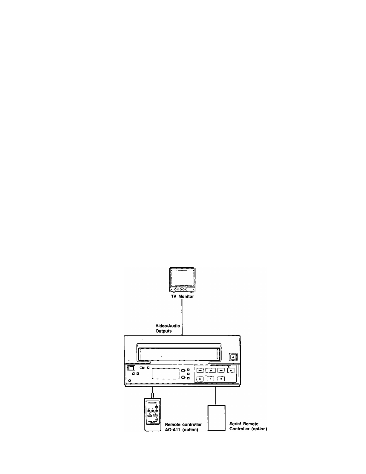
System Configurations
- 3 -
Page 4
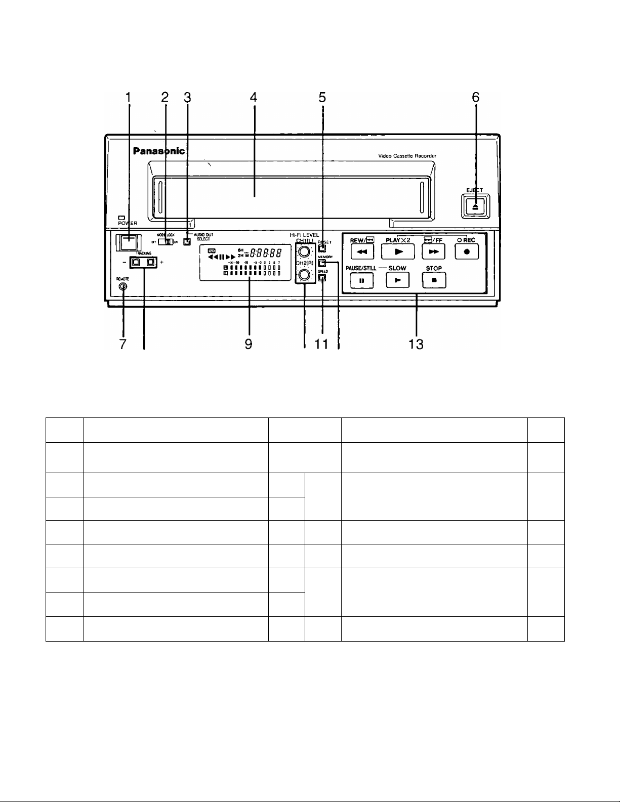
Controls
Front
8
No. Name
Power Switch —
1
Mode Lock Switch
2
Audio Out Select Button
3
4 Cassette Holder
Reset Button
5
Eject Button
6
7
Remote Control Jack (Mini-Jack)
Tracking ^ttons
8
10 12
Page No.
9 Counter/Audio level Meters
7
8
—
10
—
13
8~10
10
11
12 Memory Button 10
13
Name Page
Hi-Fi Audio CH1(L)/CH2(R)
Level Controls
Tape Speed Button
Operation Buttons
REW, PLAY, FF, REC, PAUSE/STILL,
SLOW, STOP
7, 8,
10
7
7
7~11
- 4 -
Page 5
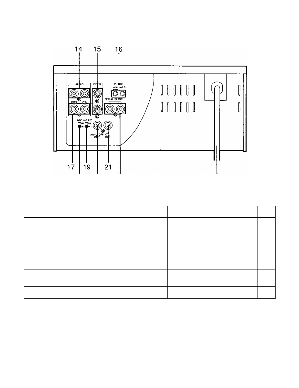
Rear
18 20
No.
Audio CH1(L)/CH2(R) IN Connectors
14
(PHONO)
15
Video IN/OUT Connectors (BNC)
V-Lock (2h*4h/6h) Controls
16
Audio CH1{L)/CH2{R) OUT Connectors
17
(PHONO)
18
AGC S\«itch*
*When this switch is set to ON, the recording
level is adjusted automatically.
Name
22
23
Page No. Name Page
6, 7,
Hi-Fi REC Switch
11.
12
6. 7,
11,
12
9
6. 8,
11
—
19
20 AUTO OFF OUT Connector (PHONO) 11
21
CTL OUT Connector (PHONO) 11
22
Serial Remote IN/OUT Connectors
23 Power Cord —
7, 11
12
- 5 -
Page 6

Connections with TV Monitor (Audio/Video)
When the connection is to be made to a TV Monitor that
does not have an 8-pin terminal {a monitor television which
has only normal audio and video connection terminals),
separate audio (phono) and video (BNC) cables are used
to make the connection.
- 6 -
Page 7

Recording
Audio Signals are recorded as described on the table.
CH
Audio^-^^
Input
Hi-Fi Normal
Preparations
• Set the Memory Button to OFF.
• Load the pre-recorded cassette tape.
Audio Level Adjustment (Hi-Fi sound oniy)
The audio level can be adjusted only for Hi-Fi audio.
Adjust the Hi-Fi Audio CH1 (L)/CH2{R) Level Controls so
that the audio level meter indication is set to 0 (so that
the 0 level is exceeded).
AUDIO OUT
SELECT
OS 6H
\«8:88-88
-oo-îO -«
. oiiiiifioaDf
-S / iO
Hi-Fi LEVEL
CH1(L) reset
■ri-, a
CH2(R) y]
I- SPEED
CHI (L)
CH2 (R)
CHI (L) &
CH2 (R)
• When Hi-Fi REC Switch is set to ON, Hi-Fi audio recording
is available.
CH1 CH1
CH2 CH2
Stereo
(CH1 & CH2)
Mixed Audio
(CH1 & CH2)
Operation
Recording starts when the REC and PLAY Buttons are
pressed simultaneously.
When the PAUSE/STILL Button is used, the sequence of
operation is as follows.
O Playback the tape and find the location which is to
be recorded. Then press the PAUSE/STILL Button.
The “ II ” indication will appear on the Counter and
VTR is set to the playback pause mode.
0 Press the REC and PLAY Buttons simultaneously. The
REC lamp now comes on and the VTR is set to the
recording pause mode.
® When the PAUSE/STILL Button is pressed again, the
VTR is released from the pause mode and recording
begins.
Tape Speed Selection
Press the Tape Speed Button to select the desired tape
speed. 2-hour (2H) or 6-hour (6H) indication will appear
on the Counter each time the Tape Speed Button is
pressed.
SPEED
2H (SP): Standard mode (recording for approx. 120
minutes using an NV-T120 tape)
6H (SLP); Super long play mode (recording for approx.
360 minutes using an NV-T120 tape)
Stopping Recording
Press the STOP Button.
Mode Lock Switch
This switch makes it impossible to switch from one VTR
operation to another.
When it is set to ON, the Power Switch and Operation
Buttons (except the Eject Button) do not function.
However, operations from the remote controller are
available.
- 7 -
Page 8

Playback
Preparations
• Press the Power Switch to ON.
• Be sure that the Mode Lock Switch is OFF.
• Insert a recorded tape.
• Turn the TV Monitor ON.
Audio Out Select Button
Set the Audio Out Select Button to the desired position.
This is to select the audio signal through Audio
CH1(L)/CH2(R) OUT Connectors. Each time the Audio Out
Select Button is pressed, the audio output mode will
change as follows:
Hi-Fi
L CH —* * R CH —* No indication (Linear)
L
AUDIO OUT
SELECT
Press
-8-8B88
-30 -10 -S -! 0 i S 7
IIIIIIDDaQ
11 I I I I D D D D
Changes
Slow Motion Playback
Press the SLOW Button during playback. The playback
picture can be viewed at a lower speed. Each time the
SLOW Button is pressed, the VTR will run at one of the
slow motion speeds shown below. To return to normal
playback, press the PLAY Button.
Normal speed -*■ 1/30
t
• If slow motion playback continues for over 10 minutes,
the VTR will go into the stop mode automatically.
• No sound is heard during slow motion playback.
1/20
1/15
1/10 1/6
1
Rewind and Fast Forward the tape
When the VTR is in stop mode:
• Press the REW Button to rewind the tape.
• Press the FF Button to move the tape forward rapidly.
Search Playback
Tape Speed
There is no need to set the tape speed since setting is
automatically made to the speed which the tape was
recorded.
Normal Playback
Press the Play Button. “ ► " indication will appear on the
Counter and playback will start.
• Press the Tracking Buttons simultaneously if the image
is partially obscured by bands of noise to move the noise
out of the picture. If the noise persists, use the or
Button for adjustment.
TRACKING
Double-speed Playback
• When the FF Button is held down while the VTR is in
the playback, slow motion playback or still, the tape will
be played back in the fonward direction at about 9 times
normal speed in SP or LP mode, and at about 11 times
normal speed in SLP mode.
• When the REW Button is held down while the VTR is
in the playback, slow motion playback or still, the tape
will be played back in the reverse direction at about 9
times normal speed in SP or LP mode, and at about 11
times normal speed in SLP mode.
• No sound is heard during search playback.
Use tapes complying with the VMS standard with this
unit. The rewind time differs depending on the hub
diameter (tape take-up volume).
• Use of Panasonic video tapes is recommended for
recording and playback.
• NV-T120 »NV-TeO
• NV-T90 • NV-T30
Press the PLAY Button during normal playback. The
playback picture can be viewed at about twice normal
playback speed. To return to normal playback, press the
PLAY Button.
• No sound is heard during double-speed playback.
- 8 -
Page 9

Still Playback After Finishing Playback
Press the PAUSE/STILL Button during normal playback or
during slow motion playback. Still playback will only return
to normal playback mode by pressing the PAUSE/STILL
Button once again.
• If noise appears during still playback, set for slow motion
mode and adjust with the Tracking Control Buttons to
minimize the bands of noise as shown below, then press
the PAUSE/STILL Button.
TRACKING
-DO
..
....
ULLLiUJliLito
• If still playback continues for more than 5 minutes, the
VTR will go into the stop mode automatically.
• A distortion may occur on the picture during still mode,
but this is not a malfunction.
• No sound is heard during still mode.
• Color program may be played back in black and white
or playback image may be dark during still mode, but
this is not a malfunction.
Press the Stop Button to stop the playback.
For playback of tapes recorded in SP mode, exchange
ability is guaranteed by the VMS standard, but a stable
playback picture may not be obtained for tapes recorded
in LP or SLP mode.
Vertical Lock Adjustment
If picture jitters vertically in STILL, adjust the V-Lock
Controls on the rear panel, but a one time adjustment
should be necessary.
If the TV Monitor has a vertical hold control, adjust this
together with the V-Lock Controls.
V-LOCK
2h(SP) 6tv{SLP)
4h(lP)
- 9 -
Page 10

Counter
Memory Stop
When the Memory Button is pressed and the “M” display
lights on the Counter, the tape can be stopped near
counter digit “00000” during FF or REW modes.
H^R level
CH1(L) reset
n □
ilCuOKr
CH2(R)
I El
f
Press until
"M" will appear.
il ■
REW/S
0 ¥
Press
Auto Stop near
counter digit
“00000"
B/FF
or
Press
Counter Reset
Pressing the Reset Button clears the counter indication to
“00000”.
Hi-R level
Ea n
W
U-
-00-3» -»
-I 9 ? » T
amili
moDD nmmiioDo
1 00 D D
□ mill
CHliL) reset
■ Ö: £. [A
CH2(R) ! /
Ö 1
Press
EÜI
n nn nn
IH
U U U U
-00-a -4 H -a » 1 1 1
Li
Audio Output
Each time the power is turned ON, Hi-Fi mode is auto
matically selected for audio output (Band □ indications
both appear on the Counter). Use the Audio Out Select
Button to select for the desired audio output.
AUDIO OUT
SELECT
E3
Press
®
2H U- V
-30 -« -S -1 0 2 S 7
IIIIIIQODD
I I I I I I 0 D D D
Hour Meter
When the Tracking Buttons are pressed simultaneously in
modes besides playback, the total number of hburs that
the VTR has been used {the cylinder has turned) is
indicated on the Counter.
ESJ
DIIIIIIIDDDD
Q I 11 I I I I D D D D
I n n n u
tuuun
2H
-00-30 -« -S -2 0 2 S 7
TRACKING
- 10 -
Page 11

AUTO OFF Output
CTL Output
If any trouble should occur, this unit is set to AUTO OFF.
At such a time, the unit stops automatically, and the REC
Lamp flashes. At the same time, signals are output from
the AUTO OFF OUT Connector on the rear panel. When
the Power Switch is set off, AUTO OFF is released.
OPEN
(Max. 12 V)
OV
OV at AUTO OFF
The CTL signal to be recorded on the tape is output in
the form shown in the figure below. It can be used for
the tape travel count, etc.
Standard
speed: 33.35mm/s
Dubbing
Refer to the figure below for the connections which apply when using two VTRs for dubbing.
Audio Cable (phono)
OPEN
(Max. 12V)
OV
AG-5210 for playback
• Memory Button: OFF
• Load the pre-recorded tape.
Operation
O Press the PLAY Button on the playback VTR to start
playback.
® Press both the REC and PLAY Buttons on the record
ing VTR at the location where the dubbing is to begin,
and proceed with dubbing.
AG-5210 for recording
• Memory Button: OFF
• Load the unrecorded tape.
© To stop the dubbing, first press the STOP Button on
the recording VTR and then press the STOP Button
on the playback VTR.
• With 6-hour recording for dubbing purposes, use the unit
with the Fli-Fi REC Switch at the OFF position.
- 11 -
Page 12

Serial Remote Control
The use of the optional serial remote controller makes it
possible to conduct recording, playback and other opera
tions from a distance, as shown in the figure.
For details, consult with, your authorized local dealer.
Note
---------
; Audio
-----------
: Video
-----------
: Serial Remote
Note
• Do not use the Remote Input/Output Connectors for any
purpose except for serial remote control since a break
down or failure may othenvise occur.
- 12 -
Page 13

Remote Controller
When the optional accessory remote controller AG-A11 is
connected to the Remote Control Jack on the front panel
of this unit, the unit can be controlled from a distance
instead of by using the buttons on the unit itself.
Troubleshooting
...Check the following points once again.
Trouble
No power
No operation starts when operation
buttons are pressed.
The playback picture is noisy or con
tains streaks.
Corrections
• Check that the Power Cord is connected to the AC Outlet.
'Check that the Power Switch is ON.
'Check that the cassette tape is inserted.
'Check the “ cl ” rnark.
When the “ ^ " mark lights:
Take out the cassette tape and leave the VTR on and let it remain at
room temperature until " rj ” mark disappears. Depending on the sur
rounding conditions, this may take several hours.
'Adjust by pressing the Tracking Control Buttons.
Refer servicing to qualified service personnel.
- 13 -
Page 14

Cautions for Use
Do not insert fingers or any other objects into the
Cassette Holder.
Avoid operating or leaving the VTR near strong mag
netic fields. Be especially careful of large audio
speakers.
Avoid operating or storing the VTR in an excessively
hot, cold, or damp environment as this may result in
damage both to the VTR and to the tape.
This unit is supplied with a 3-prong grounded AC plug—
do not try to defeat its purpose.
If the VTR is not going to be used for a length of time,
turn the power OFF and disconnect the power plug
from the AC outlet.
Do not leave a cassette tape in the VTR when not in
use.
Do not block the ventilation slots on the top of the VTR.
Use this VTR horizontally and do not place anything on
the top panel.
Cassette tape can be used only for one-side, one
direction recording. Two-way or two-track recordings
cannot be made.
Cassette tape can be used for either color or black &
white recording.
Keep the VTR away from flower vases, tubs, sinks, etc.
CAUTION: If liquids should be spilled into the VTR,
serious damage could occur. If you spill any liquid into
the VTR, remove power and consult qualified service
personnel.
Wipe the VTR with a clean, dry cloth. Never use
cleaning fluids, chemicals or wax.
Do not attempt to disassemble the VTR.
There are no user serviceable parts inside.
Refer any needed servicing to qualified service person
nel.
Dew Indication
In case of dew detection, the safety device of this VTR
will operate in order to protect the cassette tape and video
heads. In case of dew detection, the “ ^ ” mark in the
Counter lights. Take out the cassette tape and wait until
“ ^ " mark goes out with Power Switch turned ON.
“ " mark lights.
Cleaning care for video heads
The video heads are the means by which the VTR
places pictures on the tape during recording, and reads
pictures from the tape during playback.
In the unlikely event that they become dirty enough to
be clogged, no picture will be recorded or played back.
This can easily be determined if, during playback of a
known good tape, there is good sound, but no picture
{picture is extremely snowy). If this is the case, have
the VTR checked by qualified service personnel.
Note: We do not recommended that you attempt to
clean the video heads yourself.
- 14 -
Page 15

Specifications
Power Source:
Power Consumption:
Television System:
Video Recording System:
Tape Format:
Tape Speed:
Recording/Playback Time;
FF/REW Time:
Operating Temperature:
Operating Humidity:
Weight:
Dimensions:
Video
Input Level:
Output Level:
Video Horizontal Resolution:
Signal-to-Noise Ratio:
120V AC, 50-60HZ
Approx. 17 watts
EIA Standard {525 lines, 60 fields)
NTSC color signal
2 rotary heads, Helical scanning system
Luminance; FM azimuth recording
Color signal; Converted subcarrier phase shift recording
Tape width 1/2 inch (12.7 mm), high density IVHSI tape
SP; 1-5/16 i.p.s. (33.35 mm/s)
LP; 21/32 i.p.s. (16.67 mm/s)
SLP; 7/16 i.p.s. (11.12 mm/s)
360 min. with NV-T120 used in SLP mode
Approx. 3 min. with NV-T120
41°F to 104°F (5°C to 40°C)
35% to 80%
Approx. 11.2lbs. (5.1kg)
10-3/4"(W) X 13-9/16"(D) X 4-3/4'*{H)
270 X 344.5 X 120 mm
VIDEO IN (BNC), 1.0Vp-p, 750 unbalanced
VIDEO OUT (BNC), l.OVp-p, 750 unbalanced
240 lines (color mode)
45dB (color, SP mode)
Audio
Input Level:
Output Level:
Channels;
Hi-Fi Audio:
Normal Audio;
Remote:
Weight and dimensions shown are approximate.
Specifications are subject to change without notice.
AUDIO IN (PHONO), -8dBv, 47kO unbalanced
AUDIO OUT (PHONO), -8dBv, IkO unbalanced
3 Channels (Hi-Fi; 2ch, normal; 1ch)
Frequency Response; 20Hz to 20kHz
Dynamic Range; 90dB
Frequency Response; 50Hz to 10kHz (SP mode)
Signal-Noise Ratio; 43dB (SP mode)
Mini (Front)/Phono (Rear) Jacks
(1Vrms=0dB)
- 15 -
Page 16

Panasonic
Broadcast & Television Systems Company
Division of Matsushita Electric Corporation of America
Executive Office;
One Panasonic Way (3F-5), Secaucus, NJ 07094
REGIONAL OFFICES:
EASTERN ZONE:
CENTRALZONE:
SOUTHERN ZONE:
Dallas Region:
Atlanta Region:
WESTERN;
Seattle Region:
Los Angeies Region:
Government Marketing Department: 52 West Gude Drive, Rockville, MD 20850 (301 ) 738-3840
Matsushita Electric of Canada Limited
5770 Ambler Drive, Mississauga, Ontario L4W 2T3
Panasonic Sales Company
Division of Matsushita Electric of Puerto Rico Inc.
San Gabriel Industrial Park, 65th Infantry Ave., Km. 9.5, Carolina, Puerto Rico 00630
43 Hartz Way, Secaucus, NJ 07094 (201) 348-7620
1707 North Randall Road, Elgin, 1L 60123 (708) 468-5200
4500 Amon Carter Blvd., Fort Worth. TX 76155 (817) 685-1117
1854 Shackleford Ct., Suite 115, Norcross, GA 30093 (404) 717-6841
1200 Westlake Ave., North, Suite 508, Seattle, WA 98109 (206) 285-8883
6550 Katella Ave., Cypress, CA 90630 (714) 373-7271
Printed in Japan
VQT5491
S1093S-1000CÂ)
 Loading...