

Panasonic AFPX-C14R, AFPX-C14P, AFPX-C14T, AFPX-C14TD, AFPX-C14PD User Manual
...
User's Manual
PROGRAMMABLE CONTROLLER
FP-X
ARCT1F409E-9
Phone: 800.894.0412 - Fax: 888.723.4773 - Web: www.clrwtr.com - Email: info@clrwtr.com

Safety Precautions
Observe the following notices to ensure personal safety or to prevent accidents.
To ensure that you use this product correctly, read this User’s Manual thoroughly before use.
Make sure that you fully understand the product and information on safety.
This manual uses two safety flags to indicate different levels of danger.
WARNING
If critical situations that could lead to user’s death or serious injury is assumed by
mishandling of the product.
-Always take precautions to ensure the overall safety of your system, so that the whole
system remains safe in the event of failure of this product or other external factor.
-Do not use this product in areas with inflammable gas. It could lead to an explosion.
-Exposing this product to excessive heat or open flames could cause damage to the lithium
battery or other electronic parts.
-Battery may explode if mistreated. Do not recharge, disassemble or dispose of fire.
CAUTION
If critical situations that could lead to user’s injury or only property damage is
assumed by mishandling of the product.
-To prevent excessive exothermic heat or smoke generation, use this product at the values
less than the maximum of the characteristics and performance that are assured in these
specifications.
-Do not dismantle or remodel the product. It could cause excessive exothermic heat or smoke
generation.
-Do not touch the terminal while turning on electricity. It could lead to an electric shock.
-Use the external devices to function the emergency stop and interlock circuit.
-Connect the wires or connectors securely.
The loose connection could cause excessive exothermic heat or smoke generation.
-Ground the protective earth (PE) terminal (Class D grounding). Failure to do so could lead to
an electric shock.
-Do not allow foreign matters such as liquid, flammable materials, metals to go into the inside
of the product. It could cause excessive exothermic heat or smoke generation.
-Do not undertake construction (such as connection and disconnection) while the power
supply is on. It could lead to an electric shock.
Copyright / Trademarks
-This manual and its contents are copyrighted.
-You may not copy this manual, in whole or part, without written consent of
Panasonic Electric
Works SUNX Co., Ltd.
-Windows is a registered trademark of Microsoft Corporation in the United States and other
countries.
-Ethernet is a registered trademark of Fuji Xerox Co., Ltd. and Xerox Corp.
-All other company names and product names are trademarks or registered trademarks of
their respective owners.
PLC_FPX
Phone: 800.894.0412 - Fax: 888.723.4773 - Web: www.clrwtr.com - Email: info@clrwtr.com

Table of Contents
Before You Start
Differences in Functions Between Versions of Controller
Restriction on using the Add-on cassette
Programming Tool Restrictions
1. Features, Functions and Restrictions ................................................... 1-1
1.1 Features and Functions of the Unit ............................................................................ 1-2
1.2 Unit Types ................................................................................................................... 1-6
1.3 Restricti on s on Unit Combinations .......................................................................... 1-10
1.4 Programming Tools .................................................................................................. 1-14
2. Specifications and Functions of Control Unit ...................................... 2-1
2.1 Parts and Functions .................................................................................................... 2-2
2.2 Power Supply Specifications ...................................................................................... 2-5
2.3 Input Specifications .................................................................................................... 2-6
2.4 Output Spec ifications ................................................................................................. 2-8
2.5 Limitations on Number of Simultaneous Input/Output On Points .......................... 2-11
2.6 Terminal Layout ........................................................................................................ 2-20
3. Expansion Cassette and Expansion F P0 Adapter Specifications ...... 3-1
3.1 Expansion Method ...................................................................................................... 3-2
3.2 FP-X Expansion Unit ................................................................................................... 3-3
3.3 FP-X Expansion FP0 Adapter ................................................................................... 3-11
4. I/O Allocation ........................................................................................... 4-1
4.1 I/O Allocation ............................................................................................................... 4-2
4.2 Allocation of FP-X Control Unit .................................................................................. 4-3
4.3 FP0 Expansion Unit Allocation ................................................................................... 4-3
4.4 Allocation of FP0 Expansion Unit .............................................................................. 4-4
4.5 I/O All oc a t io n of FP-X Add-on Cassette ..................................................................... 4-6
5. Installation and Wiring ........................................................................... 5-1
5.1 Installation ................................................................................................................... 5-2
5.2 Installation Using Expansion Cable ........................................................................... 5-5
5.3 Expansion Method of FP0 Expansion Unit ................................................................ 5-8
5.4 How to Install Add-on Cassette .................................................................................. 5-9
5.5 Power Supply ............................................................................................................ 5-11
5.6 Wirin g of In put and Output ....................................................................................... 5-17
5.7 Wirin g of Te r m i na l B loc k .......................................................................................... 5-20
5.8 Wiring of Add-on Casset t e Terminal Block .............................................................. 5-22
5.9 Handling of Backup Batt ery...................................................................................... 5-25
5.10 Safety Measu res ...................................................................................................... 5-29
Phone: 800.894.0412 - Fax: 888.723.4773 - Web: www.clrwtr.com - Email: info@clrwtr.com

6. Tool Port and USB Port .......................................................................... 6-1
6.1 Tool Port and USB Port .............................................................................................. 6-2
6.2 Functions of Tool Port ................................................................................................ 6-3
6.3 USB Port ...................................................................................................................... 6-6
7. Communication Cassette ....................................................................... 7-1
7.1 Functions and Types .................................................................................................. 7-2
7.2 Communication Specifications ................................................................................ 7-16
7.3 Communication Funct io n 1: Comput er Link ............................................................ 7-20
7.4 Communication Function 2: General-purpose Serial Communication ................... 7-36
7.5 Communication Function 3: PC(PLC) Link .............................................................. 7-56
7.6 Communication Funct io n 4: MODBUS RTU Communication ................................. 7-75
7.7 Ethernet Co mmunicat io n (AFPX -COM5) .................................................................. 7-81
8. Application Cassette ............................................................................... 8-1
8.1 Expansion of Application Cassette ............................................................................ 8-2
8.2 Application Casset t es ................................................................................................. 8-3
8.3 Specificat io ns ............................................................................................................. 8-5
9. High-speed Counter, Pulse Output and PWM Output Functions (For Tr
Type) ............................................................................................................ 9-1
9.1 Overview of Each Fun ction s....................................................................................... 9-2
9.3 High-speed Counter Function .................................................................................. 9-11
9.4 Pulse Output Function .............................................................................................. 9-19
9.5 PWM Output Function (Pul se I/ O Cassett e) ............................................................. 9-51
10. High-speed counter, Pulse Output and PWM Output functions (For Ry
Type) .......................................................................................................... 10-1
10.1 Overview of Each Funct ions................................................................................... 10-2
10.3 High-speed Counter Fu nction ................................................................................ 10-9
10.4 Pulse Output Function (Pulse I/O Cassette) ........................................................ 10-20
10.5 PWM Output Function (Pulse I/ O Cassett e) ......................................................... 10-51
11. Security Functions .............................................................................. 11-1
11.1 Type of Security Functions..................................................................................... 11-2
11.2 Password Protect Funct ion .................................................................................... 11-3
11.3 Upload Prot ect ion ................................................................................................... 11-7
11.4 Setting Fun ction for FP M emory Loader ................................................................ 11-9
11.5 Table of Security Settings/Cancel ........................................................................ 11-13
12. Other Functions .................................................................................. 12-1
12.1 Transfer Function between Memories.................................................................... 12-2
12.2 Function of Mast er M emory Cassett e .................................................................... 12-3
12.3 P13 (ICWT) Instruction ............................................................................................ 12-8
12.4 Analog Pot entio met er ............................................................................................. 12-9
12.5 Sampling Trace Function ...................................................................................... 12-10
12.6 Time Constant Processing ................................................................................... 12-13
Phone: 800.894.0412 - Fax: 888.723.4773 - Web: www.clrwtr.com - Email: info@clrwtr.com

13. Self-Diagnostic and Troubleshooting ............................................... 13-1
13.1 Self-Diagnostic function ......................................................................................... 13-2
13.2 Troubleshooting ...................................................................................................... 13-4
14. Precautions During Programming ..................................................... 14-1
14.1 Use of Duplicat ed Output ....................................................................................... 14-2
14.2 Handling BCD Data ................................................................................................. 14-4
14.3 Handling Ind ex Regi st ers ....................................................................................... 14-5
14.4 Operation E rrors ..................................................................................................... 14-7
14.5 Instruction of Leading Edge Detection Method ..................................................... 14-9
14.6 Precautions for Programming .............................................................................. 14-13
14.7 Rewrite Funct io n Du ring RUN .............................................................................. 14-14
14.8 Processing During Forced Input and Output ....................................................... 14-19
15. Specifications...................................................................................... 15-1
15.1 Table of Specifications ........................................................................................... 15-2
15.2 Table of I/O Number Allocation ............................................................................ 15-13
15.3 Relays, Memory Areas and Con st ants ................................................................. 15-16
16. Dimensions ......................................................................................... 16-1
16.1 Dimensions ............................................................................................................. 16-2
16.2 Cable/Adapter Specifications ................................................................................. 16-4
17. Appendix ............................................................................................. 17-1
17.1 System Regist ers / Speci al Int ernal Relays / Special Data Regist ers ................... 17-2
17.2 Table of Basic Instructions ................................................................................... 17-48
17.3 Table of High-level Instr uc tions ........................................................................... 17-56
17.4 Tabl e of E rror codes ............................................................................................. 17-76
17.5 MEWTOCOL-COM Communicat io n Co mmand s .................................................. 17-89
17.6 Hexadecimal /Binary/BCD ...................................................................................... 17-90
17.7 ASCII Codes .......................................................................................................... 17-91
Phone: 800.894.0412 - Fax: 888.723.4773 - Web: www.clrwtr.com - Email: info@clrwtr.com

Phone: 800.894.0412 - Fax: 888.723.4773 - Web: www.clrwtr.com - Email: info@clrwtr.com

Before You Start
Operating environment (Use the unit within the range of the general specifications when installing)
*Ambient temperatures:0 ~ +55 ℃
*Ambient humidity: 10% to 95% RH (at 25°C, non-condensing)
*Keep the height below 2000m.
*For use in pollution Degree 2 environment.
*Do not use it in the following environments.
- Direct sunlight
- Sudden temperature changes causing condensation.
- Inflammable or corrosive gas.
- Excessive airborne dust, metal particles or saline matter.
- Benzine, paint thinner, alcohol or other organic solvents or strong alkaline solutions such as ammonia
or caustic soda.
- Direct vibration, shock or direct drop of water.
- Influence from power transmission lines, high voltage equipment, power cables, power equipment,
radio transmitters, or any other equipment that would generate high switching surges.
(Min.100mm or less)
Static electricity
-Before touching the unit, always touch a grounded piece of metal in order to discharge static electricity.
-In dry locations, excessive static electricity can cause problems.
Wiring the Power Supply to the Control Unit
- Use a power supply wire that is thicker than 2 mm2 (AWG14), and twist it.
- The unit has sufficient noise immunity against the noise generated on the power line.
However, it is recommended to take measures for reducing noise such as using a isolating transformer
before supplying the power.
- Allocate an independent wiring for each power supplying line, input/output device and operating device.
- If using a power supply without a protective circuit, power should be supplied through a protective
element such as a fuse.
- Be sure to supply power to a control and an expansion units from a single power supply.
Turning on/off of the power of all the units must be conducted simultaneously.
Power supply sequence
In order to protect the power supply sequence, make sure to turn off the control unit before the
input/output power supply. If the input/output power supply is turned off before the control unit, or if the
control unit is not shut off momentarily, the controller detects change of input level, and might conduct an
unexpected operation.
Before turning on the power
When turning on the power for the first time, be sure to take the precautions given below.
• When performing installation, check to make sure that there are no scraps of wiring, particularly
conductive fragments, adhering to the unit.
• Verify that the power supply wiring, I/O wiring, and power supply voltage are all correct.
• Sufficiently tighten the installation screws and terminal screws.
• Set the mode selector to PROG. Mode.
Phone: 800.894.0412 - Fax: 888.723.4773 - Web: www.clrwtr.com - Email: info@clrwtr.com

Before entering a program
Be sure to perform a program clear operation before entering a program.
Operation procedure when using FPWIN GR Ver.2
Select “Online Edit Mode” on the FPWIN GR “On line” menu.
Select “Clear Program” on the “Edit” menu.
When the confirmation dialog box is displayed, click on “Yes” to clear the program.
Request concerning program stor a ge
To prevent the accidental loss of programs, the user should consider the following measures.
• Drafting of documents
To avoid accidentally losing programs, destroying files, or overwriting the contents of a file, documents
should be printed out and then saved.
• Specifying the password carefully
The password setting is designed to avoid programs being accidentally overwritten. If the password is
forgotten, however, it will be impossible to overwrite the program even if you want to. Also, if a
password is forcibly bypassed, the program is deleted. When specifying the password, note it in the
specifications m anual or in another safe location in case it is forgotten at some point.
• Upload protection
When the upload protection setting is specified, programs will be disabled to be read out. If the setting
is cancelled forcibly, all programs and system registers will be deleted. Therefore, note that programs
and system registers should be managed on your own responsibility.
Backup battery
Do not install the battery when it is not used.
There is a possibility of leak if the battery remains discharged.
Phone: 800.894.0412 - Fax: 888.723.4773 - Web: www.clrwtr.com - Email: info@clrwtr.com

Differences in Functions Between Versions of Controller
Version
Usable model
Usable functions
V1.10 Ry type -
UP/DOWN switching of high-speed counter by SYS instruction
Real number basic compare instructions 18 types
STF=S1, S2 ANF=S1, S2 ORF=S1, S2
STF<>S1, S2 ANF<>S1, S2 ORF<>S1, S2
STF>S1, S2 ANF>S1, S2 ORF>S1, S2
STF>=S1, S2 ANF>=S1, S2 ORF>=S1, S2
STF<S1, S2 ANF<S1, S2 ORF<S1, S2
STF<=S1, S2 ANF<=S1, S2 ORF<=S1, S2
V1.20
System register 36 for setting expansion unit recognition time
Ry type -
MEWTOCOL master function
F145(SEND) Data send
F146(RECV) Data receive
V2.00
E356(EZPID) Easy PID instruction
Ry type Tr type
Time constant processing of input (Refer to Chapter 12.6.)
CPU input: System register setting
Other input: F182(FILTR) Time constant processing
Sampling trace function (Refer to Chapter 12.5.)
Sampling by instructions
F155(SMPL) Sampling
F156(STRG) Sampling trigger
Sampling by specifying time
Leading contact, trailing contact instructions
ST↑ AN↑ OR↑
ST↓ AN↓ OR↓
An arbitrary device can be specified for the setting value of
Timer/counter instruction.
e.g.) TML 0, DT0
Other additional convenient instructions
F252(ACHK) ASCII data check
F284(RAMP) Inclination output
Baud rate setting (300, 600, 1200 bps) by SYS instruction
High-speed operation
F0(MV) and F1(DMV) instructions Execution time: Approx. 1us
Only when every operands are without index modifier.
Note) The Ry and Tr types with the same specifications have the same version name
Function addition to existing instructions
F70(BCC) Block check code calculation
F356(EZPID) Easy PID instruction
Reference: <Programming Manual ARCT1F313E>
Phone: 800.894.0412 - Fax: 888.723.4773 - Web: www.clrwtr.com - Email: info@clrwtr.com

Restriction on usin g the Add-on cassette
Application cassettes that the version of the FP-X control unit is specified
FP-X Application cassette
Version of contro l unit
FP-X Analog output cassette
AFPX-DA2
Ver. 2.40 or later
FP-X Analog I/O cassette
AFPX-A21
FP-X Thermocouple cassette
AFPX-TC2
FP-X RTD cassette
AFPX-RTD2
Application cassettes that have restric tions wh en mor e t han one units are used simultaneously
Current output range
FP-X Application cassette
Quantity
used
Control unit
C14
C30
C60
AFPX-DA2
1 ○ ○ ○
2 - △
Note1)
△
Note1)
AFPX-A21
1 ○ ○ ○
2 - ○ ○
AFPX-DA2 + AFPX-A21
Each 1 - △
Note1)
△
Note1)
AFPX-DA2 + AFPX-COM5
Each 1 ×
Note2)
×
Note2)
×
Note2)
AFPX-A21 + AFPX-COM5
Each 1 ×
Note2)
×
Note2)
×
Note2)
AFPX-A21 + AFPX-DA2 + AFPX-COM5
Each 1 - ×
Note2)
×
Note2)
AFPX-DA2 1unit + AFPX-COM5 1unit
- ×
Note2)
×
Note2)
AFPX-A21 2units + AFPX-COM5 1unit
- ×
Note2)
×
Note2)
Note1) Up to 2 channels can be used for the current output range.
(When using two units, it is possible to use the 2-ch current output range and 2-ch voltage output range.)
Note2) The AFPX-DA2 and AFPX-A21 both cannot be used with the AFP-COM5 (Ethernet).
Voltage output range ( W hen u sing with the output current of 1 mA or below)
FP-X Application cassette
Quantity
used
Control unit
C14
C30
C60
AFPX-DA2
1 ○ ○ ○
2 - ○ ○
AFPX-A21
1 ○ ○ ○
2 - ○ ○
AFPX-DA2 + AFPX-A21
Each 1 - ○ ○
AFPX-DA2 + AFPX-COM5
Each 1 ○ ○ ○
AFPX-A21 + AFPX-COM5
Each 1 ○ ○ ○
AFPX-A21 + AFPX-DA2 + AFPX-COM5
Each 1 - ○ ○
AFPX-DA2 1unit + AFPX-COM5 1unit
-
○ ○
AFPX-A21 2units + AFPX-COM5 1unit
-
○ ○
Note) In the voltage output range, when using them with the output current at 1 mA to 10 mA, the
condition is the same as the current output range.
Phone: 800.894.0412 - Fax: 888.723.4773 - Web: www.clrwtr.com - Email: info@clrwtr.com

Programming Tool Restrictions
Restrictions on usable programming tools depending on the units (as of Feb. 2009)
Type of programming tool
Type of unit
AFPX-C14R
AFPX-C30R
AFPX-C60R
AFPX-C14T, C14TD, C14P, C14PD
AFPX-C30T, C30TD, C30P, C30PD
AFPX-C60T, C60TD, C60P, C60PD
Windows software
FPWIN GR Ver.2
Used
(Ver. 2.5 or later)
Used
(Ver. 2.70 or later)
FPWIN GR Ver.1
Not used
Not used
Windows software
Conforms to
IEC61131-3
FPWIN Pro
Ver.6
Used Used
FPWIN Pro
Ver.5
Used
(Ver. 5.1 or later)
Used
(Ver. 5.22 or later)
Handy programming
unit
AFP1113V2
AFP1114V2
Not used Not used
AFP1113
AFP1114
Not used Not used
AFP1111A
AFP1112A
AFP1111
AFP1112
Not used Not used
FP memory loader
AFP8670
AFP8671
Used
(Only programs and system registers can be transmitted.)
Note: Precautions concerning ver sion upgrade
• In case of using FPWIN GR Ver.1, please purchase upgrade model FPWIN GR Ver.2.
• FPWIN GR Ver. 2.0 can be upgraded to Ver. 2.5 or later free of charge at our web site.
• FPWIN Pro Ver. 6.0 can be upgraded free of charge at our web site.
• The handy programming unit cannot be used.
Do not download any programs for other units such as FP1 to the FP-X using the handy programming
unit.
Website address:
http://panasonic-denko.co.jp/ac/e/dl/software-list/patch/plc.jsp
Phone: 800.894.0412 - Fax: 888.723.4773 - Web: www.clrwtr.com - Email: info@clrwtr.com

Phone: 800.894.0412 - Fax: 888.723.4773 - Web: www.clrwtr.com - Email: info@clrwtr.com

Chapter 1
Features, Functions and Restrictions
Phone: 800.894.0412 - Fax: 888.723.4773 - Web: www.clrwtr.com - Email: info@clrwtr.com

1.1 Features and Functi ons of the Unit
Features
• Com pact size general-purpose PLC that is suitable for the small-scale facility control.
• Can be directly connected to a personal computer using USB communication port.
• High dimensional security functions to deal with copying programs.
• Supports analog control.
• Following items are provided as options,
- Application cassettes, such as the positioning control function by the high-speed counter and
pulse output.
- Fulfilling communication cassettes.
- Realtime clock function.
Basic functions as compact size general-purpose PLC suitable for the small-scale facility control
Basic functions including the followings are equipped even though it is a general-purpose style such as
AC power supply, screw terminal block and relay output.
1. 32k-step program capacity
2. 0.32 µs command processing speed
3. Max. 382-points I/O control
Single-phase 8-channel and 2-phase 4 channel high-speed count er functions are equipped for
the control unit.
Fulfilling function enhancement
Various add-on cassettes are avai lable as options (such as 10 types of application cassettes and
6 types of communication cassette).
• Application cassettes
DC 8-point input type, transistor 8-point NPN output type, transistor 6-point PNP output type, DC 4-point
input + transistor 3-point NPN output type, analog 2-ch output type, analog 2-ch input + analog 1-ch
output type, thermocouple 2-ch type, RTD 2-ch type, analog 2-ch input type, high-speed counter input +
pulse output type, master memory type with realtime clock (32k-step program can be copied and stored.)
• Communication cassettes
1-ch RS232C type, 2-ch RS232C type, 1-ch RS485/RS422 changeover type, 1-ch RS232C + 1-ch
RS485 type, Ethernet + 1-ch RS232C type, 2-ch RS485 type
FP0 expansion unit s can be connected as well as the excl usive expansion unit.
A maximum of 3 FP0 expansion units can be connected using the expansion FP0 adapter.
A personal com puter can be directly connected with the USB c ommunicat ion port.
A personal computer can be directly connected with the USB cable (excluding C14).
The USB⇔RS232C conversion adapter/cable is not necessary.
(A tool port (RS232C) is also equipped.)
Phone: 800.894.0412 - Fax: 888.723.4773 - Web: www.clrwtr.com - Email: info@clrwtr.com
High dimensional security functions to deal with copying programs.
The uploading disabling function prohibits uploading (reading) programs in the PLC main unit and
prevent illegal copying.
(It also enables to transfer the programs to the FP-X master memory cassette, when the uploading
disabling function is specified).
The protection for programs can be selected from
3 security methods.
• 4-digit password
• 8-digit password
•
Uploading disabling
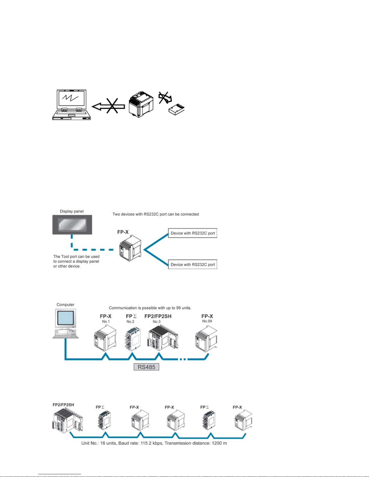
A full rang e of communication functions
Using the Tool port (RS232C) provided as a standard feature on the main unit, communication can be
carried out with a display panel or computer. Additionally, communication cassettes with RS232C,
RS485 and Ethernet interfaces are available as an option. Installing a 2-channel RS232C type
communication cassette in the FP-X makes it possible to connect two devices with RS232C port. A full
lineup of communication functions means you can also work with 1:N communication (up to 99 units)
and PC(PLC) link function (up to 16 units).
Controlling two devices with RS232C port with one FP-X
When using the 2-channel RS232C type communication cassette
1:N communication possible wi t h up to 99 stations (units)
When using the 1-channel RS485/RS422 type communication cassette
When using the 1-channel RS485 and 1-channel RS232C in combination
Link with FP2 and FP
Σ is possible
Data sharing between small size and medium size PLCs is easily achievable in one network.
The FP-X supports MEWNET-W0, and the programless PLC link with the FP2 or FPΣ is possible.
Phone: 800.894.0412 - Fax: 888.723.4773 - Web: www.clrwtr.com - Email: info@clrwtr.com
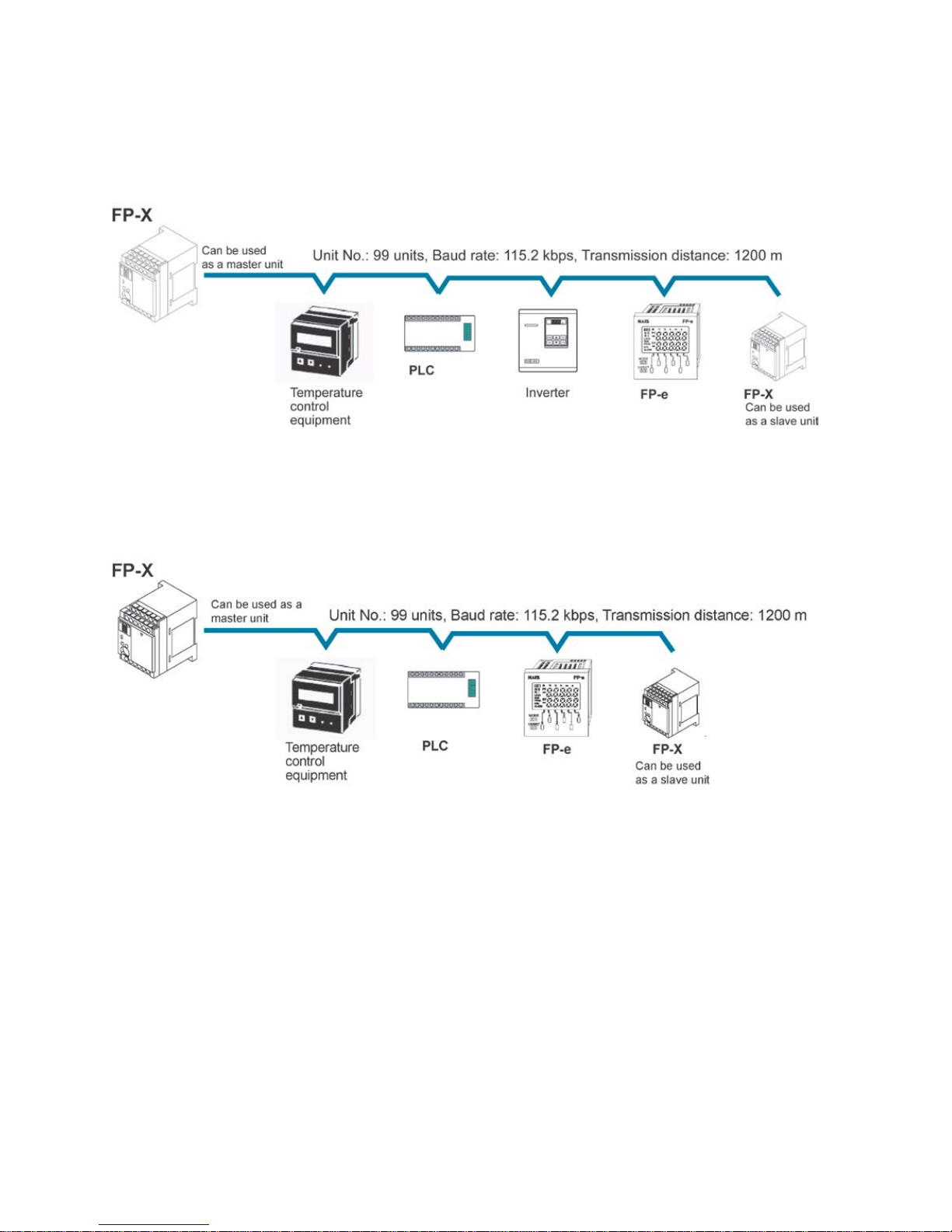
Supports Modbus RTU
It can be used as a master unit/slave units (F145 and F146 instructions).
It can be easily communicated with a temperature control device, inverter, FP-e or overseas PLCs.
It is possible to communicate with up to 99 units
MEW TOCOL communication
It can be used as a master unit/slave units (F145 and F146 instructions).
It can be easily communicated with a PLC, image processor, temperature control device, message
runner or eco-power meter.
It is possible to communicate with up to 99 units
Phone: 800.894.0412 - Fax: 888.723.4773 - Web: www.clrwtr.com - Email: info@clrwtr.com
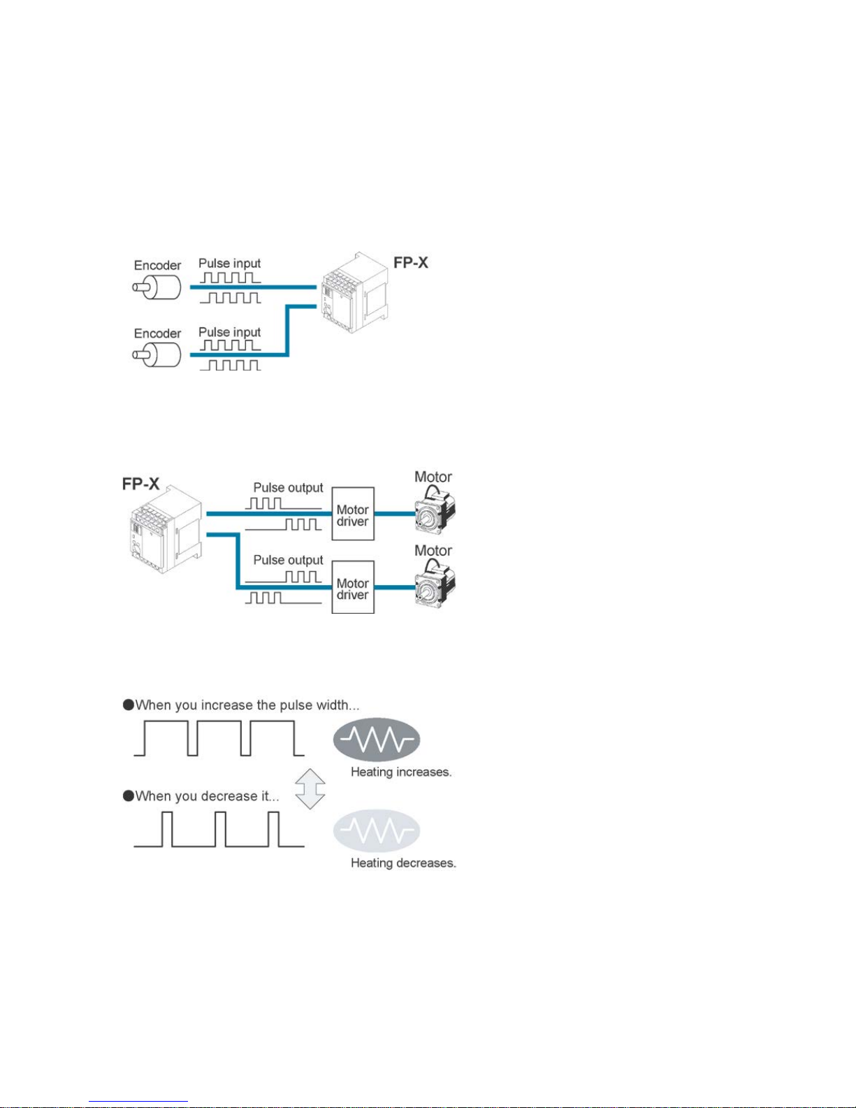
Positioning control supported through high-speed counter and pulse output
With the FP-X Tr type, a high-speed counter function can be used by using the CPU I/O.
With the FP-X Ry type, a high-speed counter and pulse output functions can be used by using the pulse
I/O cassette. The pulse output function supports frequencies of up to 100kHz, enabling positioning
control using a stepping motor or servo motor.
Note) The pulse I/O cassette cannot be used for the FP-X Tr type.
Measurement using high-speed counter supported
Increment input mode, decrement input mode, 2-phase input mode, individual input mode, and direction
discrimination mode are supported.
Note) Differs depending on combinations.
Positioning control based on puls e output supported
Pulse/direction and clockwise/counter –clockwise output are supported.
Heater control based on PWM output function supported
The pulse output at any duty ratio can be picked up with special instruction.
Analog potentiometer ( volume dial)
An analog potentiometer (volume dial) is provided as a standard feature. This can be used in
applications such as analog timers, without using the programming tools.
Realtime clock function can be added
Optional FP-X master memory cassette (AFPX-MRTC) and backup battery enables the realtime clock
function.
Phone: 800.894.0412 - Fax: 888.723.4773 - Web: www.clrwtr.com - Email: info@clrwtr.com
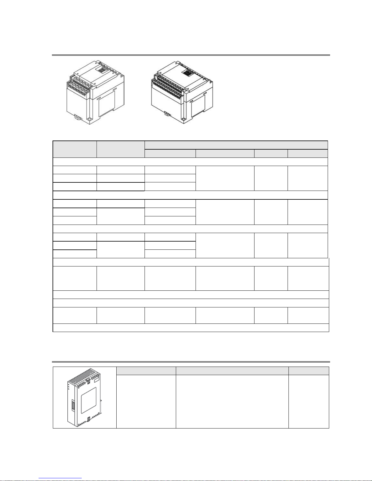
1.2 Unit Types
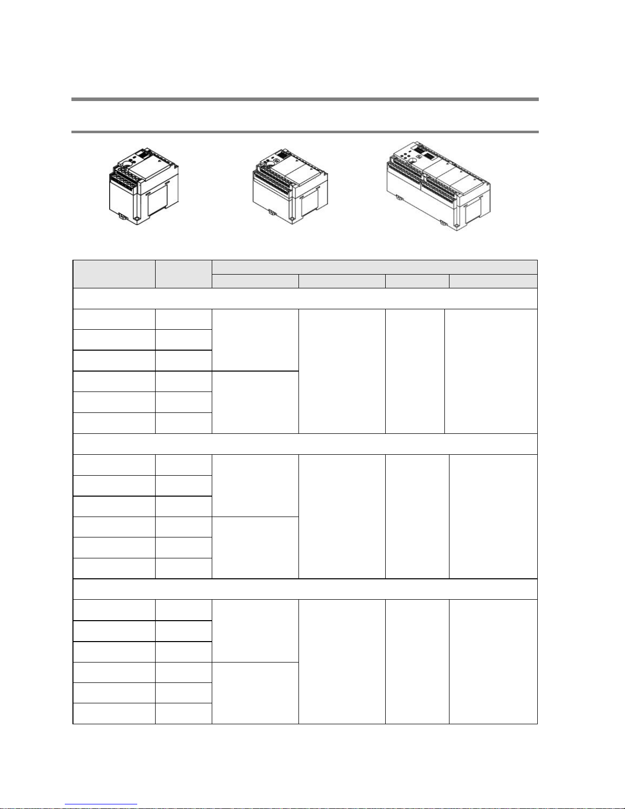
1.2.1 FP-X Control Units
C14
C30
C60
Product No.
No. of I/O
points
Specifications
Power supply
Input
Output
Connection
Relay type ( Ry typ e)
AFPX-C14R 8/6
100 to 240 V AC
24 V DC
(Common
polarities
+ & - common)
Relay Terminal block
AFPX-C30R 16/14
AFPX-C60R 32/28
AFPX-C14RD 8/6
24 V DC
AFPX-C30RD 16/14
AFPX-C60RD 32/28
Transi s tor type (NPN) (Tr type)
AFPX-C14T 8/6
100 to 240 V AC
24 V DC
(Common
polarities
+ & - common)
Transistor
(NPN)
Terminal block
AFPX-C30T 16/14
AFPX-C60T 32/28
AFPX-C14TD 8/6
24V DC
AFPX-C30TD 16/14
AFPX-C60TD 32/28
Transi s tor type (PNP) (Tr type)
AFPX-C14P 8/6
100 to 240 V AC
24 V DC
(Common
polarities
+ & - common)
Transistor
(PNP)
Terminal block
AFPX-C30P 16/14
AFPX-C60P 32/28
AFPX-C14PD 8/6
24V DC
AFPX-C30PD 16/14
AFPX-C60PD 32/28
Phone: 800.894.0412 - Fax: 888.723.4773 - Web: www.clrwtr.com - Email: info@clrwtr.com
1.2.2 FP-X Expansion Unit
E14/E16 E30
Product No.
No. of I/O
points
Specifications
Power supply
Input
Output
Connection
Relay type ( Ry typ e)
AFPX-E16R 8/8 -
24 V DC
(Common polarities
+ & - common)
Relay
Terminal
block
AFPX-E30R
16/14
100 to 240 V AC
AFPX-E30RD
16/14
24 V DC
Transi s tor type (NPN) (Tr type)
AFPX-E16T 8/8 -
24 V DC
(Common polarities
+ & - common)
Transistor
(NPN)
Terminal
block
AFPX-E30T
16/14
100 to 240 V AC
AFPX-E30TD
24V DC
Transi s tor type (PNP) (Tr type)
AFPX-E16P
8/8
-
24 V DC
(Common polarities
+ & - common)
Transistor
(PNP)
Terminal
block
AFPX-E30P
16/14
100 to 240 V AC
AFPX-E30PD 24V DC
Input-only typ e
AFPX-E16X
16/0
(X300 to X30F)
-
24 V DC
(Common polarities
+ & - common)
-
Terminal
block
- The input specifications are the same as AFPX-E16R.
Output-only type (R elay type)
AFPX-E14YR
0/14
(Y300 to Y30D)
- - Relay
Terminal
block
- The output specifications are the same as AFPX-E16R.
An 8-cm expansion cable is provided with expansion unit
1.2.3 FP-X Expa ns ion FP 0 Adapt er
Name
Specifications
Product No.
FP-X Expansion
FP0 adapter (with 8
cm expansion
cable, power supply
cable)
For connecting FP0 expansion unit AFPX-EFP0
Phone: 800.894.0412 - Fax: 888.723.4773 - Web: www.clrwtr.com - Email: info@clrwtr.com
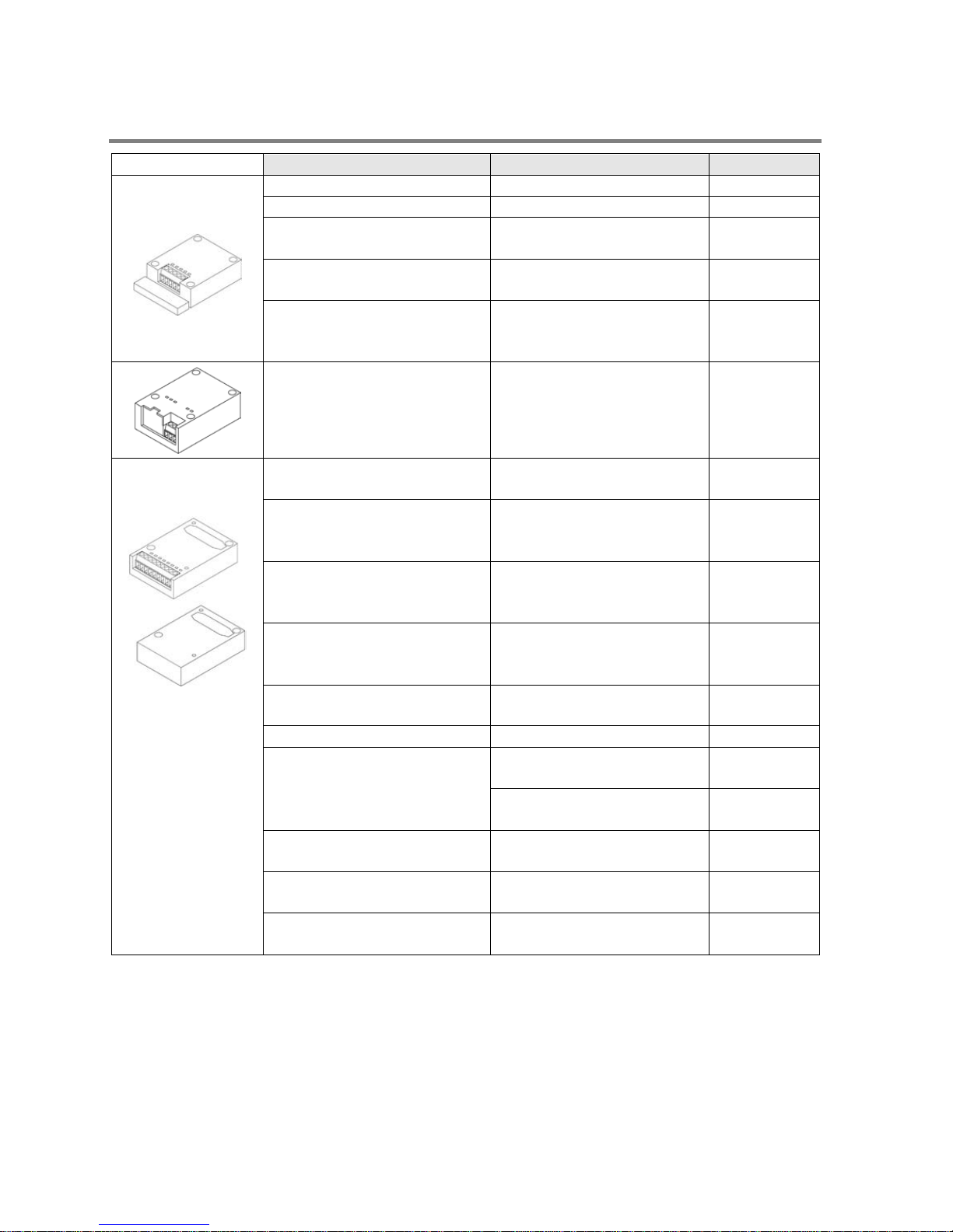
1.2.4 Add-on Cas settes (Comm un ication casset tes/ A pplication ca ssette s)
Name
Specifications
Product No.
Communication
cassette
FP-X Communication cassette
5-wire 1-channel RS232C
AFPX-COM1
FP-X Communication cassette
3-wire 2-channel RS232C
AFPX-COM2
FP-X Communication cassette
1-channel RS485/RS422
(insulated)
AFPX-COM3
FP-X Communication cassette
1-channel RS485 (insulated)
3-wire 1-channel RS232C
AFPX-COM4
FP-X Communication cassette
2-channel RS485 (insulated)
(non-insulated between
channels)
AFPX-COM6
FP-X Communication cassette
Ethernet,
3-wire 1-channel RS232C
AFPX-COM5
Application
cassette
FP-X Analog input cassette
2-channel analog input
(non-insulated)
AFPX-AD2
FP-X Analog output cassette
2-channel analog output
(insulated) (insulated
between channels)
AFPX-DA2
FP-X Analog I/O cassette
2-channel analog input
(insulated) + 1-channel
analog output (insulated)
AFPX-A21
FP-X Thermocouple cassette
2-channel thermocouple input
(insulated) (insulated
between channels)
AFPX-TC2
FP-X RTD cassette
2-ch RTD input (insulated)
(insulated between channels)
AFPX-RTD2
FP-X Input cassette 8-point DC input AFPX-IN8
FP-X Output cassette
8-point transistor output
(NPN)
AFPX-TR8
6-point transistor output
(PNP)
AFPX-TR6P
FP-X I/O cassette
4-point DC input + 3-point
transistor output (NPN)
AFPX-IN4T3
FP-X Pulse I/O cassette
2-ch high-speed counter +
1-ch pulse output
AFPX-PLS
FP-X Master memory cassette
Master memory + realtime
clock
AFPX-MRTC
Phone: 800.894.0412 - Fax: 888.723.4773 - Web: www.clrwtr.com - Email: info@clrwtr.com
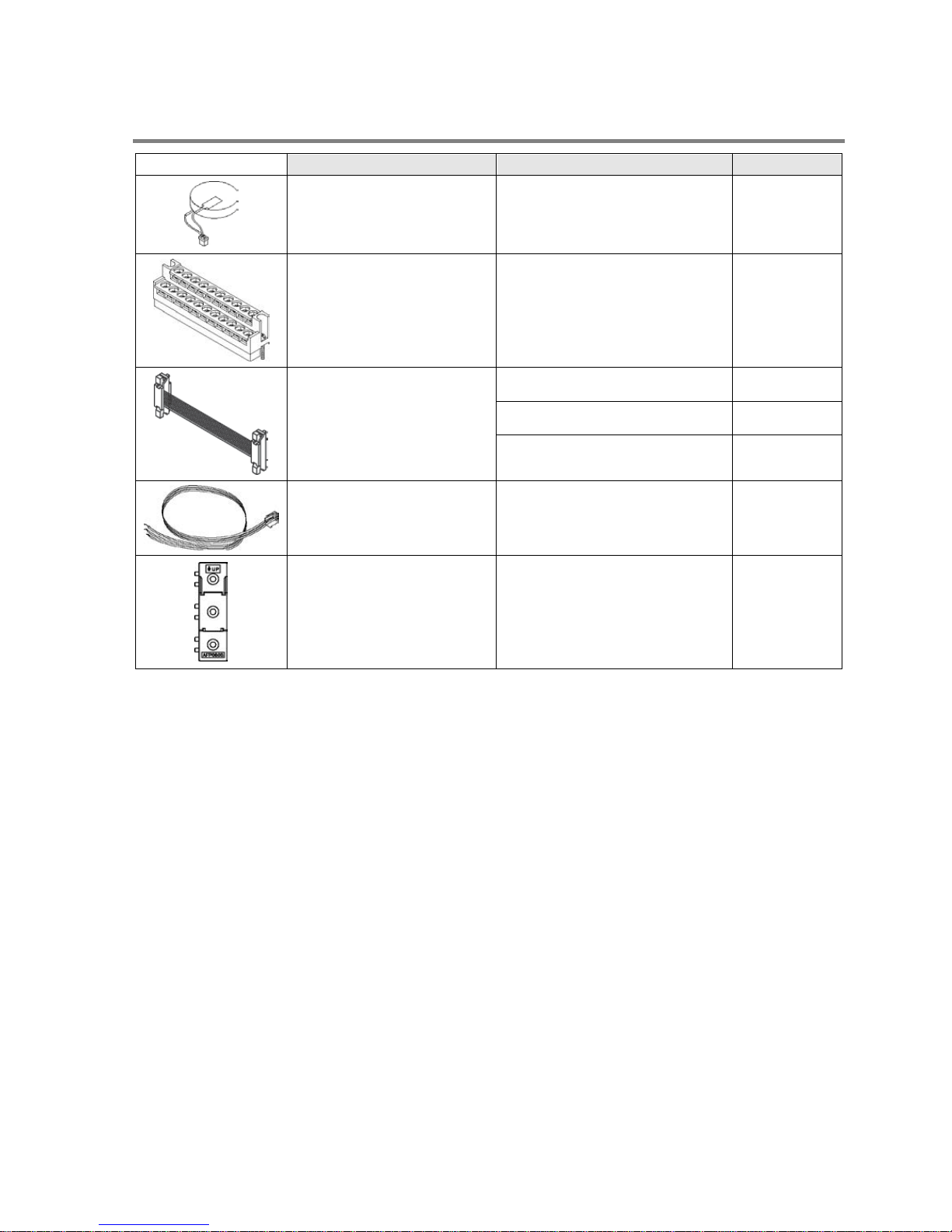
1.2.5 Related Part s
Name
Description
Product No.
FP-X Backup battery
Necessary for the backup of
data registers, etc. or for using
the realtime clock function.
AFPX-BATT
FP-X terminal block
(C30/C60)
For C30/C60 control unit
for E30 expansion I/O unit
with 21-pin cover (no printing)
4 pcs/pack
AFPX-TAN1
FP-X expansion cable
Note)
8 cm AFPX-EC08
30 cm AFPX-EC30
80 cm AFPX-EC80
FP0 power supply cable
For Expansion FP0 adapter,
Length: 1 m
AFP0581
FP0 mounting plate
(slim type)
Used for expansion FP0
adapter and FP0 Expansion
unit, 10 pcs/pack
AFP0803
Note) The total length of the expansion cable should be within 160 cm.
Phone: 800.894.0412 - Fax: 888.723.4773 - Web: www.clrwtr.com - Email: info@clrwtr.com
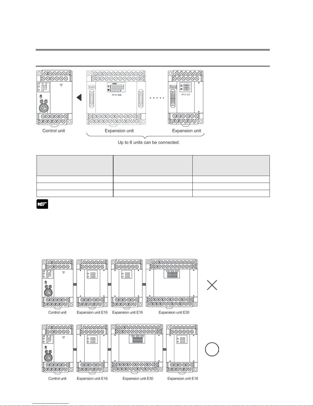
1.3 Restrictions on Uni t Combina t ions
1.3.1 Restr ictions on FP-X Expansion Unit
Controllable I/O points
Type of control unit
Number of I/O points whe n
using control unit
Number of I/O points whe n
using 8 units of E30
expansion I/O unit
FP-X C14 Control unit 14 points Max. 254 points
FP-X C30 Control unit 30 points Max. 270 points
FP-X C60 Control unit
60 points
Max. 300 points
Note:
- Up to eight units of FP-X can be connected, however, the restrictions on each expansion unit vary.
- For AFPX-E16/E14: Two units cannot be connected consecutively since the power should be supplied
from the unit with the power supply (as no power supply is built in AFPX-E16).
E16 expansion I/O unit cannot be connected on the right side of the control unit or AFPX-E30.
- For AFPX-E30: There is no restriction on AFPX-E30 so that up to 8 units can be connected
consecutively.
- The total length of the expansion cable should be within 160 cm.
Phone: 800.894.0412 - Fax: 888.723.4773 - Web: www.clrwtr.com - Email: info@clrwtr.com
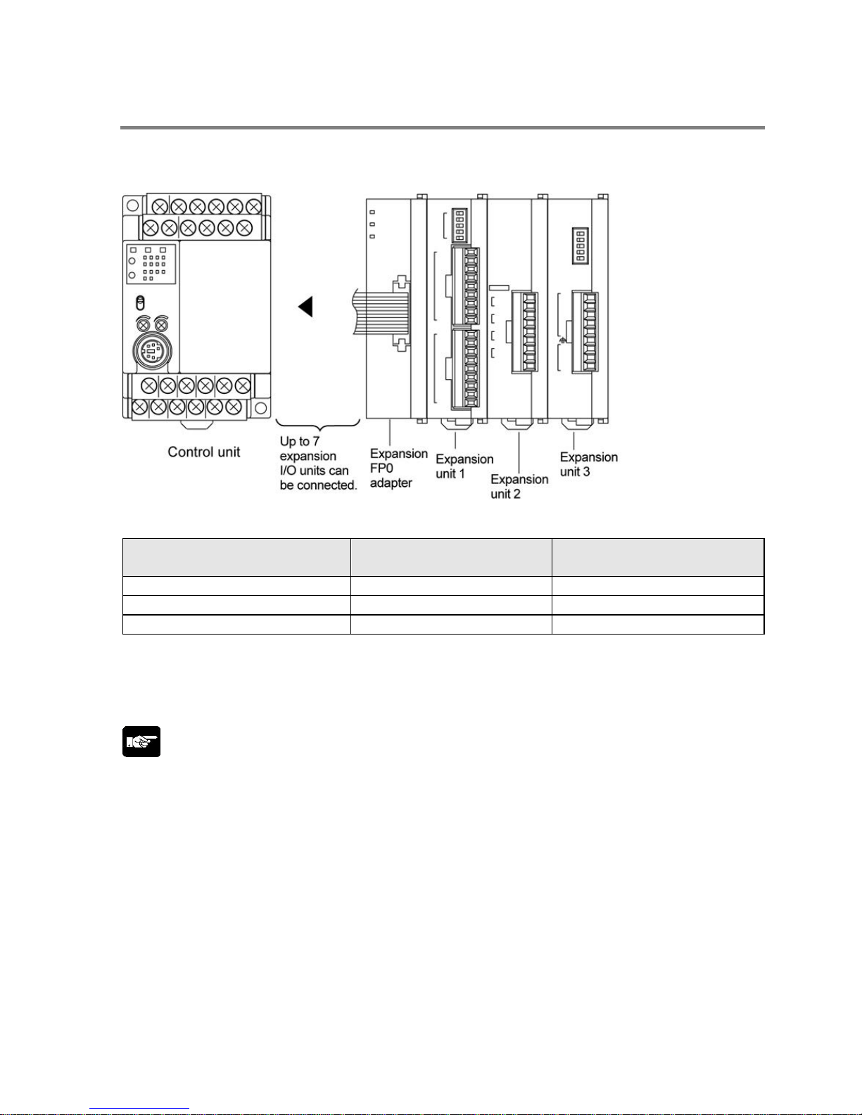
1.3.2 Restrictions on FP0 Expansion U nit
Up to three dedicated FP0 expansion units can be added using the FP-X and the expansion FP0 adapter.
The relay output type and the transistor output type can be used in combination.
Controllable I/O points
Type of control unit
Number of I/O points whe n
using control unit
Number of I/O points whe n
using FP0 expansion unit
FP-X C14 Control unit
14 points
Max. 110 points
FP-X C30 Control unit 30 points Max. 126 points
FP-X C60 Control unit
60 points
Max. 156 points
Note1) Up to seven FP-X expansion I/O units can be also installed between the control unit and the
expansion FP0 adapter.
Note2) Only one expansion FP0 adapter can be installed at the last position of the FP-X expansion bus.
(It should be installed at the right hand side of the AFPX-E16 and E30.)
Note:
• Install the FP0 thermocouple unit on the right side of other expansion units. If it is installed on the left
side, the total precision will deteriorate.
• Install the FP0 CC-Link slave unit on the right side of the other expansion units. There is no expansion
connector on the right side.
Phone: 800.894.0412 - Fax: 888.723.4773 - Web: www.clrwtr.com - Email: info@clrwtr.com

1.3.3 Restrictions on FP-X Add-on Cassette
The add-on cassette is installed in the cassette mounting part 1 and 2 (only the cassette mounting part 1
is available for C14) of the control unit.
Phone: 800.894.0412 - Fax: 888.723.4773 - Web: www.clrwtr.com - Email: info@clrwtr.com
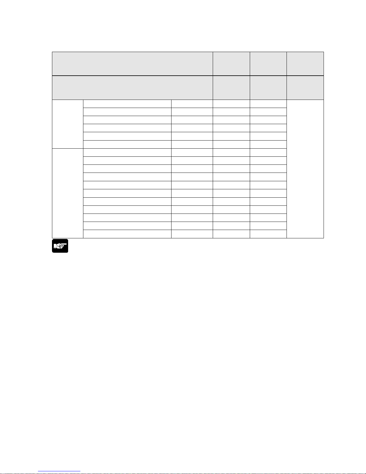
A: Available, N/A: Not available
Restrictions on control unit
FP-X C14
FP-X C30
FP-X C60
FP-X C30
FP-X C60
FP-X C60
Type of add-on cassette
Cassette
mounting
part 1
Cassette
mounting
part 2
Expansion
connector
part
Communication
cassette
FP-X Communication cassette AFPX-COM1 A N/A
The add-on
cassette
cannot be
installed.
FP-X Communication cassette
AFPX-COM2
A
N/A
FP-X Communication cassette AFPX-COM3 A N/A
FP-X Communication cassette
AFPX-COM4
A
N/A
FP-X Communication cassette AFPX-COM5 A N/A
FP-X Communication cassette
AFPX-COM6
A
N/A
Application
cassette
FP-X Analog input cassette AFPX-AD2 A A
FP-X Input cassette
AFPX-IN8
A
A
FP-X Analog output cassette AFPX-DA2 A A
FP-X Analog I/O cassette
AFPX-A21
A
A
FP-X Thermocouple cassette AFPX-TC2 A A
FP-X RTD cassette
AFPX-RTD2
A
A
FP-X Output cassette AFPX-TR8 A A
FP-X Output cassette
AFPX-TR6P
A
A
FP-X I/O cassette AFPX-IN4T3 A A
FP-X Pulse I/O cassette
AFPX-PLS
A
Note5)
A
Note5)
FP-X Master memory cassette AFPX-MTRC A
Note1)
A
Note1)
Note:
1. Only one FP-X master memory cassette AFPX-MRTC can be installed. If 2 units are installed, E26
(user ROM error) will occur.
2. One application cassette can be installed in either cassette mounting part 1 or 2 of C30/C60.
3. As only one communication cassette can be installed in the cassette mounting part 1, it should be
installed on the application cassette if the application cassette is installed. (It cannot be installed in the
cassette mounting part 2.)
4. The add-on cassette cannot be installed in the expansion connector part of C60 (it does not work).
5. The pulse I/O cassette cannot be installed on the FP-X Tr type.
Phone: 800.894.0412 - Fax: 888.723.4773 - Web: www.clrwtr.com - Email: info@clrwtr.com
1.4 Programming Tools
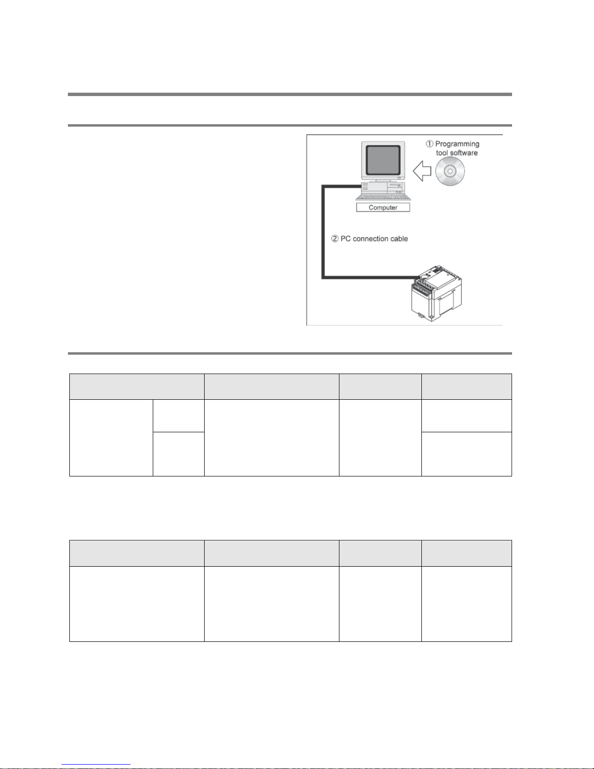
1.4.1 Tools Needed for Programming
1. Programming tool software
- The tool software can also be used with the FP
series.
- “FPWIN Pro Ver.6” or “FPW IN GR Ver.2” Windows
software is used with FP-X.
FPWIN GR Ver.1x, NPST-GR and FP
Programmer cannot be used.
2. PC connection c able
- The dedicated cable is available.
- A commercial USB cable can be used for the
connection for C30/C60 control unit.
1.4.2 Soft ware En vir onmen t and Su itable Cabl e
Standard ladder diagram tool software FPWIN-GR Ver.2
Type of software OS (Operating system)
Hard disk
capacity
Product No.
FPWIN GR Ver.2
Englishlanguage menu
Full type
Windows98
WindowsMe
Windows2000
WindowsXP
Windows Vista
Windows7
40MB or more
AFPS10520
Upgrade
version
AFPS10520R
Note1) Ver.1.1 must be installed to install the upgrade version.
Note2) Ver.2.0 can be upgraded to the latest version after Ver. 2.1 free of charge at our web site
(http://panasonic-denko.co.jp/ac/e/dl/software-list/patch/plc.jsp). Use the latest version.
Conforms to IEC61131-3 programming tool software FPWIN-Pro Ver.6
Type of software OS (Operat ing sy ste m)
Hard disk
capacity
Product No.
FPWIN Pro Ver.6
English-language menu
Windows2000
WindowsXP
Windows Vista
Windows7
100MB or more FPWINPROFEN6
Note1) The small type and upgrade version is not available for Ver.6.
Note2) Ver.6.0 can be upgraded to the latest version after Ver. 6.1 free of charge at our web site
Phone: 800.894.0412 - Fax: 888.723.4773 - Web: www.clrwtr.com - Email: info@clrwtr.com

Type of comput er and suitable cable
For the connection between a personal computer (RS232C) and the control unit (RS232C)
PC side connector
PLC side connector
Specifications
Product No.
D-sub 9-pin
female-Mini DIN round 5-pin
L type (3 m)
AFC8503
female-Mini DIN round 5-pin Straight type (3 m) AFC8503S
Note) Note) A USB/RS232C conversion cable is necessary to connect the unit to the USB port of a
personal computer using a PC connection cable.
For the connection between a personal computer (USB) and the cont r ol unit (USB)
USB cable (For C30 and C60 only)
Use a commercial cable.
Cable type
Length
USB 2.0 (or 1.1) AB type
Max. 5 m
Phone: 800.894.0412 - Fax: 888.723.4773 - Web: www.clrwtr.com - Email: info@clrwtr.com

Phone: 800.894.0412 - Fax: 888.723.4773 - Web: www.clrwtr.com - Email: info@clrwtr.com

Chapter 2
Specifica tions and Functions of Control
Unit
Phone: 800.894.0412 - Fax: 888.723.4773 - Web: www.clrwtr.com - Email: info@clrwtr.com
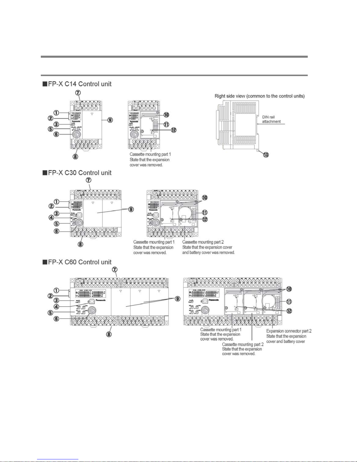
2.1 Parts and Functions
2.1.1 Parts and Functions
Phone: 800.894.0412 - Fax: 888.723.4773 - Web: www.clrwtr.com - Email: info@clrwtr.com
 Loading...