

Panasonic AFPE224300, AFPE224305, AFPE224322, AFPE224302, AFPE214325 User Manual

Phone: 800.894.0412 - Fax: 888.723.4773 - Web: www.clrwtr.com - Email: info@clrwtr.com

Phone: 800.894.0412 - Fax: 888.723.4773 - Web: www.clrwtr.com - Email: info@clrwtr.com

Table of Contents
Precautions before using FP-e unit
Programming tools
1.Features and Configurations.................................................................. 1-1
1.1 Features and Functions..................................................................................................1-2
1.1.1 Features......................................................................................................................1-2
1.1.2 Functions....................................................................................................................1-2
1.2 Unit Name and Product Number....................................................................................1-3
1.2.1 FP-e control unit .........................................................................................................1-3
1.2.2 Related parts ..............................................................................................................1-3
1.3 Programming Tool...........................................................................................................1-4
1.3.1 When using a tool software........................................................................................1-4
2.Functions and I/O specifications............................................................ 2-1
2.1 Section Names and Functions.......................................................................................2-2
2.2 Display Modes and Functions........................................................................................2-4
2.2.1 Display modes and functions......................................................................................2-4
2.2.2 Mode Displays............................................................................................................2-5
2.3 Input and Output Specifications....................................................................................2-6
2.3.1 Input specifications.....................................................................................................2-6
2.3.2 Output specifications ..................................................................................................2-8
2.4 Display/Front Operation Switch Specifications ...........................................................2-9
2.5 Calendar timer................................................................................................................2-10
2.5.1 Area for calendar timer.............................................................................................2-10
2.5.2 Setting of calendar timer function.............................................................................2-10
2.5.3 Accuracy of calendar timer.......................................................................................2-11
2.6 Limitations in data hold/non-hold function ................................................................2-12
3.Installation and Wiring ............................................................................ 3-1
3.1 Installation........................................................................................................................3-2
3.1.1 Operating environment...............................................................................................3-2
3.1.2 Mounting and Removing the Unit...............................................................................3-5
3.2 Terminal Layout Diagram and Terminal Block Wiring.................................................3-6
3.2.1 Terminal layout diagram.............................................................................................3-6
Phone: 800.894.0412 - Fax: 888.723.4773 - Web: www.clrwtr.com - Email: info@clrwtr.com

3.2.2 Terminal block wiring..................................................................................................3-6
3.3 Power Supply Wiring.......................................................................................................3-8
3.3.1 Power supply wiring....................................................................................................3-8
3.3.2 Grounding...................................................................................................................3-9
3.4 Wiring of Input and Output...........................................................................................3-10
3.4.1 Input wiring................................................................................................................3-10
3.4.2 Output wiring.............................................................................................................3-12
3.4.3 Common precautions for input and output wiring.....................................................3-12
3.5 Wiring COM. Port...........................................................................................................3-13
3.6 Safety Measures ............................................................................................................3-16
3.6.1 Safety measures.......................................................................................................3-16
3.6.2 Momentary power failures ........................................................................................3-17
3.6.3 Protection of power supply and output sections.......................................................3-17
3.7 Memory backup battery ................................................................................................3-18
3.7.1 Installation of memory backup battery.....................................................................3-18
(For FP-e unit with a calendar timer function) ...................................................................3-18
3.7.2 System register setting.............................................................................................3-18
(For FP-e unit with a calendar timer function) ...................................................................3-18
4.Display and Settings in N (Normal) Mode..............................................4-1
4.1 Display and operation in N (Normal) mode...................................................................4-2
4.2 Instructions to control the display.................................................................................4-3
4.2.1 F180 (SCR): Screen display instruction, Number of steps: 9.....................................4-3
4.2.2 F180 (SCR) instruction: FPWIN GR Wizard............................................................. 4-8
4.2.3 F181 (DSP) : Screen change instruction Number of steps: 3 ................................ 4-9
4.3 N mode sample program...............................................................................................4-10
4.4 Display screen and lock with the program .................................................................4-11
5.Data Display and Settings in S (Switch) Mode......................................5-1
5.1 Display and operation in S (Switch) mode....................................................................5-2
5.2 S mode sample program.................................................................................................5-3
6.Data Display and Settings in R (Register) Mode ................................... 6-1
6.1 Display and operation in R (Register) mode.................................................................6-2
6.2 Operation in R (Register) mode......................................................................................6-3
6.2.1 Specifying the device type..........................................................................................6-3
6.2.2 Changing the data ......................................................................................................6-4
Phone: 800.894.0412 - Fax: 888.723.4773 - Web: www.clrwtr.com - Email: info@clrwtr.com

6.2.3 Changing the unit No. of COM. port...........................................................................6-5
7.I (I/O Monitor) Mode................................................................................. 7-5
7.1 I/O monitor........................................................................................................................7-5
8.PID Control............................................................................................... 8-5
8.1 PID Control.......................................................................................................................8-5
8.1.1 Operation of PID control.............................................................................................8-5
8.2 PID control instruction....................................................................................................8-5
8.2.1 F355 (PID)..................................................................................................................8-5
8.3 PID control sample program ..........................................................................................8-5
8.4 Example of temperature control ....................................................................................8-5
9.Specifications .......................................................................................... 9-5
9.1 Specifications ..................................................................................................................9-5 9
9.1.1 General specifications ................................................................................................9-5
99
9.1.2 Performance specifications ........................................................................................9-5
99
9
.1.3 Specifications (High-Speed Counter/Pulse Output/PWM Output) .............................9-5 9
9.1.4 Functions and Restrictions (High-Speed Counter/Pulse Output/PWM Output).........9-5
9.2 I/O Allocation....................................................................................................................9-5
9.3 Relays,memory Areas and Constants...........................................................................9-5
9.4 ASCII characters displayed in the FP-e unit.................................................................9-5
9
.4.1 Available ASCII characters.........................................................................................9-5
9
.4.2 ASCII code and display..............................................................................................9-5
10.Dimensions .......................................................................................... 10-5
10.1 Dimensions ..................................................................................................................10-5
Phone: 800.894.0412 - Fax: 888.723.4773 - Web: www.clrwtr.com - Email: info@clrwtr.com

11. Appendix ......................................................................................11-1
11.1 System Registers / Special Internal Relays / Special Data Registers... 11-3
11.1.1 Table of System Registers for FP-e.......................................................11-5
11.1.2 Table of Special Internal Relays for FP-e..............................................11-9
11.1.3 Table of Special Data Registers for FP-e ............................................11-13
11.2 Table of Basic Instructions.................................................................. 11-20
11.3 Table of High-level Instructions........................................................... 11-54
11.4 Table of Error codes.......................................................................... 11-114
11.5 MEWTOCOL-COM Communication Commands.............................. 11-128
11.6 Hexadecimal/Binary/BCD.................................................................. 11-129
11.7 ASCII Codes...................................................................................... 11-130
Phone: 800.894.0412 - Fax: 888.723.4773 - Web: www.clrwtr.com - Email: info@clrwtr.com

Precautions before using FP-e unit
Installation environment
Do not use the FP-e Control Unit in the places where it will be exposed to the followings:
- Direct sunlight and ambient temperature outside the range of 0ºC to 55ºC (32°F to 131°F).
- Ambient humidity outside the range of 30% to 85% RH(at 25ºC) and sudden temperature changes
causing condensation.
- Inflammable or corrosive gas.
- Excessive vibration or shock.
- Excessive airborne dust, metal particles or salts.
- Water or oil in any from including spray or mist.
- Benzine, paint thinner, alcohol or other organic solvents or strong alkaline solutions such as ammonia
or caustic soda.
- Influence from power transmission lines, high voltage equipment, power cables, power equipment,
radio transmitters, or any other equipment that would generate high switching surges.
Static electricity
- Before touching the unit, always touch a grounded piece of metal in order to discharge static electricity.
- In dry locations, excessive static electricity can cause problems.
Cleaning
- Do not use thinner based cleaners because they deform the unit case and fade the colors.
Power supply
- An insulated power supply with an internal protective circuit should be used. The power supply for the
control unit operation is a non-insulated circuit.
- If using a power supply without a protective circuit, power should be supplied through a protective
element such as a fuse.
- If an incorrect voltage is directly applied, the internal circuit may be damaged or destroyed.
Power supply sequence
- Have the power supply sequence such that the power supply of the control unit turns off before the
power supply for input and output turns off.
- If the power supply for input and output is turned off before the power supply of the
control unit turns off, the control unit will detect the input fluctuations and may begin an unscheduled
operation.
Before turning on the power
When turning on the power for the first time, be sure to take the precautions as shown below.
- When performing installation, confirm that there are no scraps of wiring, particularly conductive
fragments, adhering to the unit.
- Confirm that the power supply wiring, I/O wiring, and power supply voltage are all correct.
- Sufficiently tighten the installation screws and terminal screws.
- Set the RUN/PROG. switch to PROG. mode.
Before entering a program
Be sure to perform a program clear operation before entering a program.
Operation procedure when using Windows software FPWIN GR Ver. 2
1. Press “CTRL” and “F2” keys at the same time to switch the display to “Online Monitor.”
2. Select [Edit (E)] → [Program Clear (L)] on the menu.
3. When the confirmation dialog box appears, click [Yes (Y)] to clear the program.
Storing a program
To prevent the accidental loss of programs, users are requested to take the following measures.
Drafting documents
To avoid accidentally losing programs, destroying files, or overwriting the contents of a file,
documents should be printed out and then saved.
Specifying the password carefully
The passward setting is designed to avoid programs being accidental ly overwritten. If the password is
forgotten, however, it will be impossible to overwrite the program even if you want to. Also, if a
passward is forcibly cleared, the program is deleted. When spesifying the passward, note it in the
spcifications or in another safe locaton in case it is forgotten at some point.
Battery
Do not install the battery when it is not used.
There is a possibility of leak if the battery remains discharged.
Phone: 800.894.0412 - Fax: 888.723.4773 - Web: www.clrwtr.com - Email: info@clrwtr.com

Programming tools
(As of Apr., 2004)
Type Restrictions
Instruction used/Function
restrictions
FPWIN GR
Ver. 2
Available. Available from Ver. 2.2 or higher.
*1)
Windows software
FPWIN GR
Ver. 1
Not available. Not available.
Windows software
conforms to IEC
61131-3
FPWIN Pro
Ver. 4
Available Available from Ver. 4.1 or higher.
*2)
NPST-GR
Ver. 4
MS-DOS software
NPST-GR
Ver. 3
Not available. Not available.
AFP1113V2
AFP1114V2
Not available.
Instructions and functions described
in *3 can not be used.
Use FPWIN GR or FPWIN Pro.
AFP1113
AFP1114
Not available. Not available.
Handy
programming unit
AFP1111A
AFP1112A
AFP1111
AFP1112
Not available. Not available.
Notes: Precautions concerning programming tools
*1) Customers who use FPWIN GR Ver. 2 can upgrade the version from
our HP free of charge.
Use Ver. 2.3 or higher to set the COM. port to MODBUS S RTU.
(MODBUS S RTU is available from FP-e main unit Ver.1.2 or higher.)
*2) Customers who use FPWIN Pro Ver.4 can upgrade the version from our
HP free of charge.
The COM. port cannot be set to MODBUS S RTU.
It will be available from FPWIN Pro Ver. 5.
*3) Functions that can not be used using a handy programming unit
(AFP1113V2 and AFP1114V2):
- Screen display registry instruction <F180 (SCR)>
- Screen display switch instruction <F181 (DSP)>
- Leading edge differential instruction (Initial execution type) <DFI>
- On-delay timer instruction <TML>
- Clear multiple steps instruction <SCLR>
- Floating-point type data instruction <F309> to <F338>
- PID processing instruction <F355>
Phone: 800.894.0412 - Fax: 888.723.4773 - Web: www.clrwtr.com - Email: info@clrwtr.com

Chapter 1
Features and Configurations
Phone: 800.894.0412 - Fax: 888.723.4773 - Web: www.clrwtr.com - Email: info@clrwtr.com
1-2
1.1 Features and Functions
1.1.1 Features
1. IP 66-compliant panel mounting type
Mounting panel front is waterproof and compliant with IP66, IEC standard.
Compact controller: 48 mm (H), 48 mm (W), 70 mm (D)
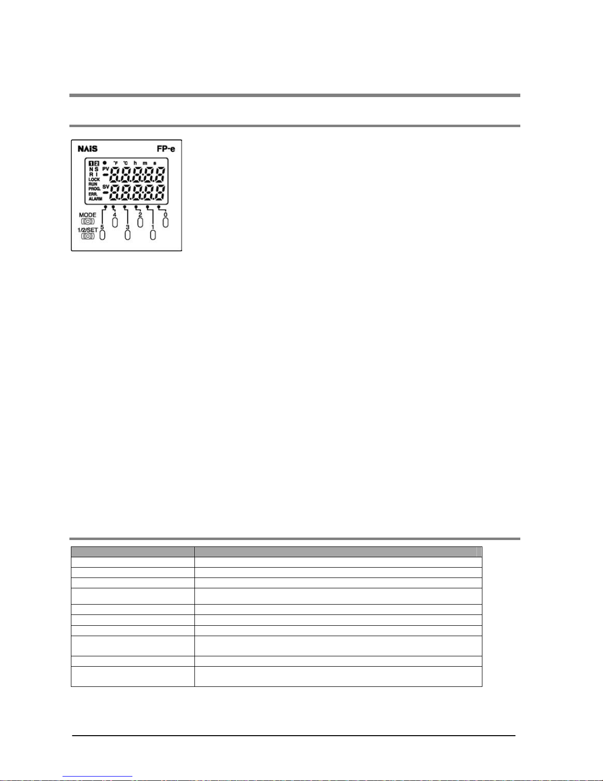
2. Indicator function
Simple characters and numerical values (with a minus sign) can be displayed up to 5 digits. *
4 modes (N, S, R, and I modes) can be selected.
Those 4 modes each have 2 selectable displays.
Data indication section can be displayed in red, green, or orange.
3. Operation switches
Set data can be changed.
This switch can be used as an input switch.
4. Control function
In addition to the functions of the programmable controller FP0 series, pulse output and high-speed
counter functions are installed.
General-purpose communication COM. port is included as standard unit.
FP-e units with the calendar timer or thermocouple input function are also provided.
*Numerical values are displayed only in 16-bit. The data can be disp layed in a bit, decimal, or
hexadecimal system.
1.1.2 Functions
Item Description
Power supply 24V DC
Input 8 points
*1)
(24V DC)
Output 6 points (5 points : Tr. NPN 0.5A, 1 point : Ry 2A)
Program capacity 2.7 k step
Operation speed 0.9 µ/step (Basic instruction)
I/O update and Base time 2 ms
*2)
Pulse catch/Interrupt input 6 points in total (High-speed counter included)
High-speed counter
Single phase: 4 points (10 kHz in total)
Dual phase: 2 points (2 kHz in total)
*3)
Pulse output 2 points (10 kHz in total)
*4)
COM. port
RS232C/RS485 (according to models)
* Must be provided aside from tool ports
*1) Thermocouple input type: 6 points
*2) Thermocouple input type: 2 to 3 ms (Typical), Max: 15 ms. (The time takes longer every 250 ms.)
*3) Thermocouple input type: 5 kHz (Single phase), 1 kHz (Dual phase)
*4) Thermocouple input type: 5 kHz
Phone: 800.894.0412 - Fax: 888.723.4773 - Web: www.clrwtr.com - Email: info@clrwtr.com

1-3
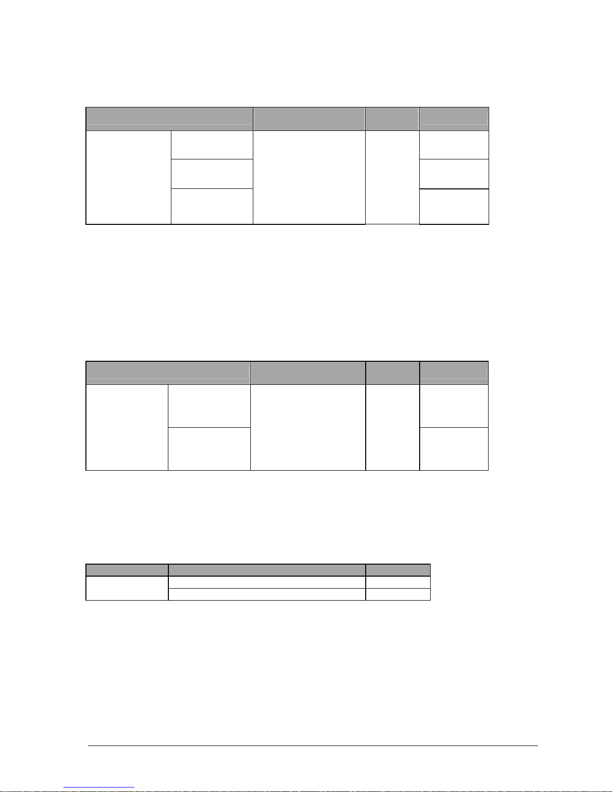
1.2 Unit Name and Product Number
1.2.1 FP-e control unit
Name
Number of I/O
points
Thermo-
couple
input
Calendar
timer
COM
port
Product No.
FP-e control unit
(Standard type)
Input: 8/Output: 6
(Tr. NPN: 5, Ry: 1)
Not
available
Not
available
RS232C AFPE224300
FP-e control unit
(Calendar timer type)
Input: 8/Output: 6
(Tr. NPN: 5, Ry: 1)
Not
available
Available RS232C AFPE224305
FP-e control unit
(Thermocouple input type)
Input: 6/Output: 6
(Tr. NPN: 5, Ry: 1)
2 points Available RS232C AF PE214325
FP-e control unit
(Standard type)
Input: 8/Output: 6
(Tr. NPN: 5, Ry: 1)
Not
available
Not
available
RS485 AFPE224302
FP-e control unit
(Thermocouple input type)
Input: 6/Output: 6
(Tr. NPN: 5, Ry: 1)
2 points
Not
available
RS485 AFPE214322
1.2.2 Related parts
Name Description Product No.
Terminal driver Used for connecting a terminal AFP0806
Rubber gasket
Used for a waterproof unit
(included in a unit package)
ATC18002
Mounting frame
Used for mounting a unit.
(included in a unit package)
ATA4811
Battery for FPΣ
Used for calendar timer and operation memory backup.
(Included in calendar timer function-provided type and
themocouple input type)
AFPG804
Protective cover Oil resistant soft cover AQM4803
Terminal socket set
Set of four types of terminal socket for FP-e
(Maintenance parts)
AFPE804
Color: Black, with NAiS·FP-e mark
AFPE803
Color: Ash gray, without NAiS·FP-e mark
AFPE805
Panel cover
(20-pack)
Color: Black, without NAiS·FP-e mark
AFPE806
Phone: 800.894.0412 - Fax: 888.723.4773 - Web: www.clrwtr.com - Email: info@clrwtr.com
1-4
1.3 Programming Tool
1.3.1 When using a tool softwar e
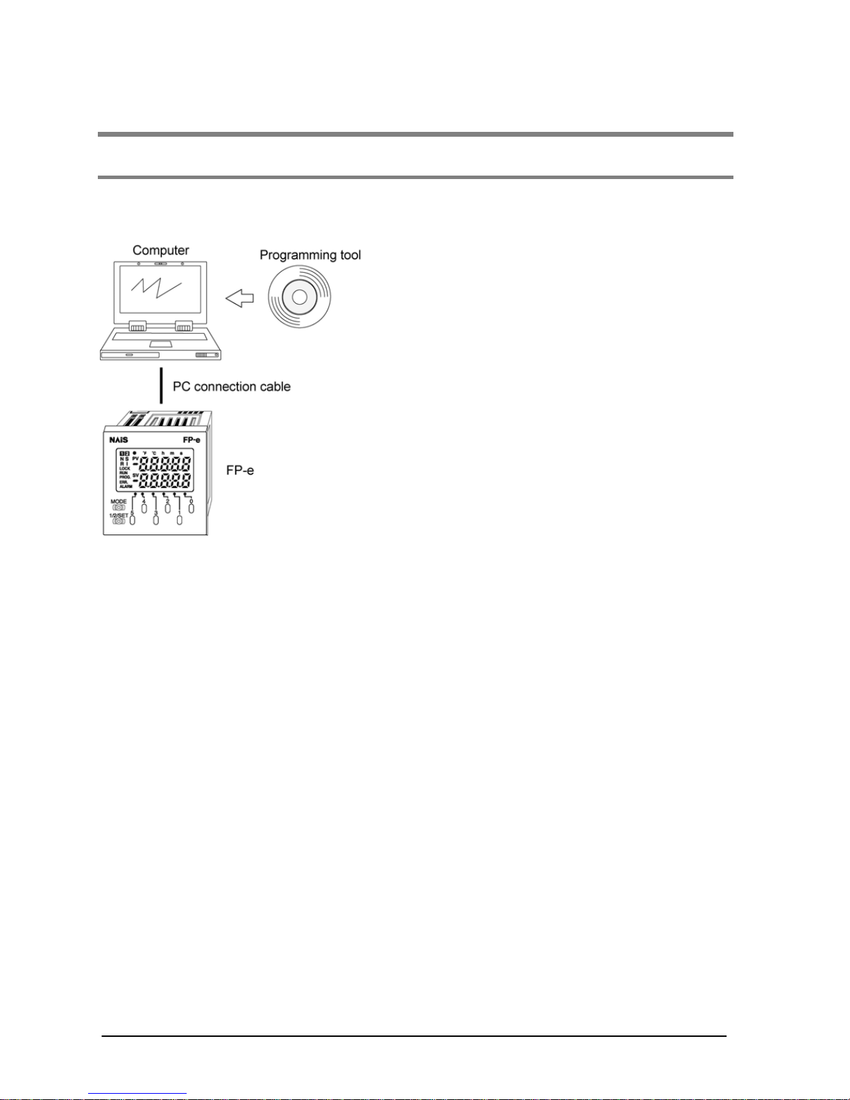
- Tools needed for programming
1. Programming tool software
· The tool software can also be used with the FP series.
· The "FPWIN GR Ver. 2” or “FPWIN Pro Ver. 4” (for Windows) is used with FP-e controllers.
· Note that the earlier “FPWIN GR Ver. 1,” “NPST-GR (DOS version), or “FP programmer” cannot
be used.
2. PC connection cables
This cable is needed for connection between the FP-e unit and the computer.
Phone: 800.894.0412 - Fax: 888.723.4773 - Web: www.clrwtr.com - Email: info@clrwtr.com
1-5
Software environment and suitable cables
- Standard ladder diagram tool software “FPWIN GR Ver. 2”
Type of software
OS
(Operating system)
Hard disc
capacity
Product No.
Full type AFPS10520
Upgraded version AFPS10520R
FPWIN GR Ver. 2
English-language
menu
Small type
WINDOWS
95 (OSR2 or higher)/
98/Me/
NT (Ver. 4.0 or higher)/
2000/XP
40 MB
or more
AFPS11520
Note 1) To use the “FP-e,” software Ver. 2.2 or higher is required.
The software Ver. 2.3 or higher is required to set the COM. port to MODBUS S RTU.
Customers who use the Ver.2 software can upgrade it through our HP free of charge.
Note 2) Customers who use the “FPWIN GR Ver.1” can use the “FPWIN GR Ver. 2” after purchasing
the upgraded version software.
(The upgraded version software can be installed only when the “Ver.1.1” has been previo usly
installed.
Note 3) Small type version can be used for the “FP-e,” “FPΣ,” “FP0,” “FP1,” and “FP-M” series.
- IEC61131-3-compliant programming tool software FPWIN Pro Ver.4
Type of software
OS
(Operating system)
Hard disc
capacity
Product No.
Full type AFPS50540
FPWIN Pro Ver.4
English-language
menu
Small type
WINDOWS
95 (OSR2 or higher)/
98/Me/
NT (Ver. 4.0 or higher)/
2000/XP
100 MB
or more
AFPS51540
Note 1)To use the “FP-e software Ver. 4.1 or higher is required.
Customers who use the Ver. 4 software can upgrade it through our HP free of charge.
The COM. port cannot be set to MODBUS S RTU. It will be available from FPWIN Pro Ver. 5
Note 2) Small type version can be used for the “FP-e,” “FPΣ,” “FP0,” “FP1,” and “FP-M” series.
- Type of computer and suitable cables
Connecter Connecter on PLC side Product No.
Mini DIN round 5-pin AFC8503
D-Sub 9-pin
Mini DIN round 5-pin streight type AFC8503S
Phone: 800.894.0412 - Fax: 888.723.4773 - Web: www.clrwtr.com - Email: info@clrwtr.com

1-6
Phone: 800.894.0412 - Fax: 888.723.4773 - Web: www.clrwtr.com - Email: info@clrwtr.com

2-1
Chapter 2
Functions and I/O specifications
Phone: 800.894.0412 - Fax: 888.723.4773 - Web: www.clrwtr.com - Email: info@clrwtr.com
2-2
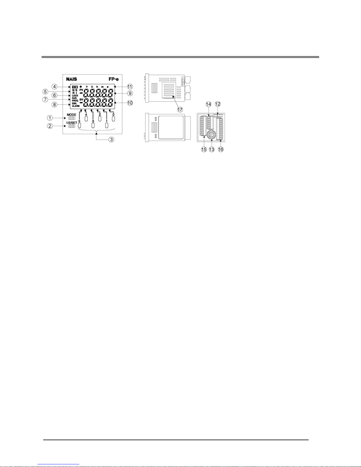
2.1 Section Names and Functions
①Display mode switch
Changes the display mode to N, S, R, or I.
When the switch is pressed for 2 seconds or longer, the front switch key is locked. Pressing the switch
once more for 2 seconds or longer unlocks the key.
②Screen changeover switch
Changes the display to 1
st
Screen or 2nd Screen.
When the numerical data is changed, pressing the switch for one second or longer determines the data.
③Front operation switch
Changes the data. This switch is also used as the input switch.
Pressing a switch of the digit for which you would like to change the numerical value during the data
change adds one to the numerical value displayed.
(Data display blinks during the data change.)
④Display screen No.
Indicates the screen number used currently. “1
st
” or “2nd” is displayed.
⑤Display mode
Indicates “N,” “S,” “R,” or “I.”
⑥LOCK display
Shows that the switch is locked.
(This display is lit when “LOCK” using the front switch or “ALL LOCK” using the program is selected.)
⑦RUN/PROG. display
Displays the operation mode (RUN or PROG.).
⑧ERR./ALARM display
Indicates when an error or an alarm occurs.
ERR. : Lights up if an error is detected during the self-diagnostic function.
ALARM: Lights up if a hardware error occurs, or if operation slows because of the program,
and the watchdog timer is activated.
Phone: 800.894.0412 - Fax: 888.723.4773 - Web: www.clrwtr.com - Email: info@clrwtr.com

2-3
⑨Data display (Upper section)
N and S modes
- Display the data registered using the F180 (SCR) command.
- Display the data in red, green, or orange.
R mode
- Displays the address in the memory area in green.
I mode
- Displays the external input monitor in green.
⑩Data display (Lower section)
N and S modes
- Display the data registered using the F180 (SCR) command.
- Blink when the numerical value is changed.
- Display the data in red, green, or orange.
R mode
- Displays the data in the memory area in green.
I mode
- Displays the external output monitor in green.
⑪Setting display
Indications (e.g.●, ºF, ºC, h, m, s, SV, and PV) and dot between the digits can be displayed individually
by the ladder program.
⑫Mode switch (RUN/PROG.)
Changes the mode of the FP-e unit to RUN or PROG. Modes can also be changed from the
programming tool.
When performing remote switching from the programming tool, the position of the mode s witch and the
actual mode of operation may differ.
Verify the mode with the RUN/PROG. display on the front.
When power is supplied, the mode displayed is activated.
⑬Tool port (RS232C)
Used to connect a programming tool.
A commercial mini-DIN 5-pin connector is used for the tool port on the control unit.
*The followings are default settings. Use the system register to change the settings.
Baud rate---------------------------9600bps
Character bit length--------------8 bit
Parity check------------------------Odd parity
Stop bit------------------------------1 bit
⑭Power supply/COM. port connector
⑮Input connector
⑯Output connector
⑰Battery cover
Note: Colors in the display section
④ to ⑦ and ⑪: green ⑧: red
⑨ and ⑩: red, green, or orange (N and S modes), green (R and I modes)
Pin No. Name Abbr. Signal direction
1 Signal ground SG 2 Send data SD Unit → External device
3 Receive data RD Unit ← External device
4 (Not used) - 5 +5V +5V Unit → External device
Phone: 800.894.0412 - Fax: 888.723.4773 - Web: www.clrwtr.com - Email: info@clrwtr.com
2-4
2.2 Display Modes and Functions
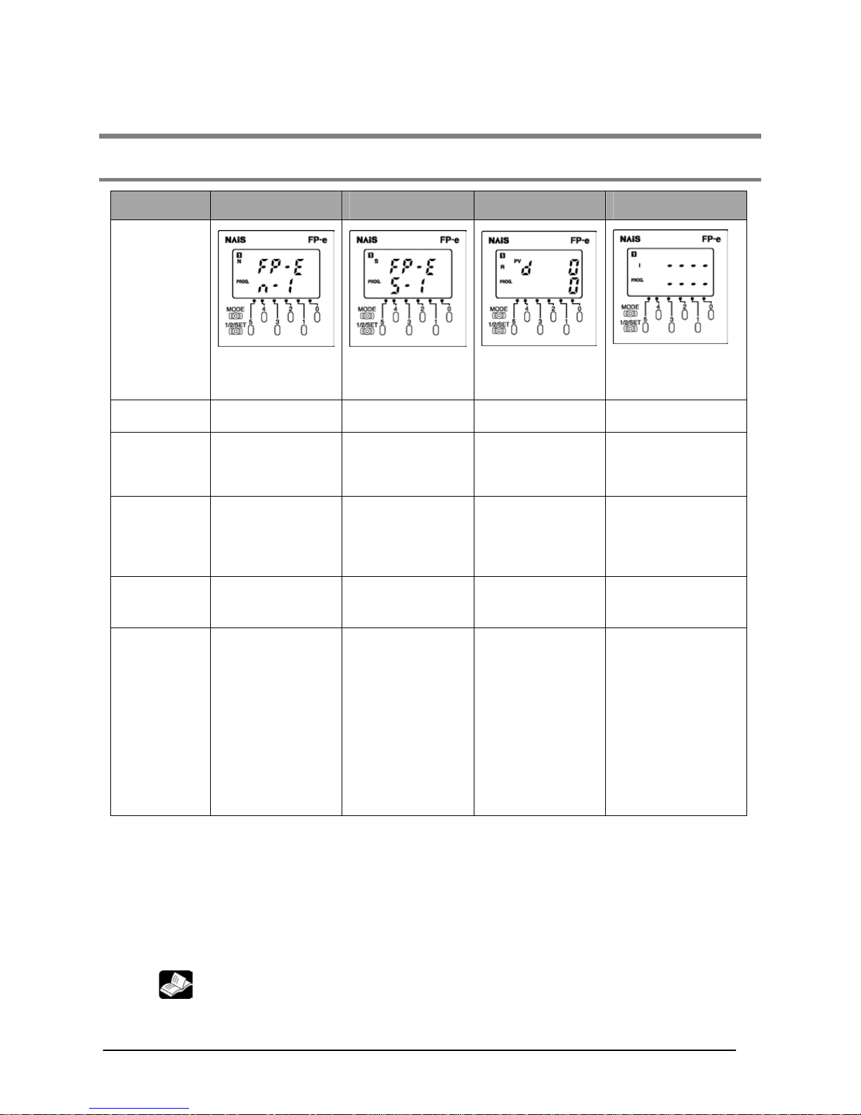
2.2.1 Display modes and functi ons
Mode
N mode
(Normal mode)
S mode
(Switch mode)
R mode
(Register mode)
I mode
(I/O monitor mode)
Screen
Registered by F180
(SCR) command
Registered by F180
(SCR) command
Data monitor of the
internal memory
· External I/O monitor
· Thermocouple input
monitor
Number of
screens
2 2 2 2
Display in
the upper
section
Arbitrary data
display
(Characters/Nume
rical values)
Arbitrary data
display
(Characters/Nume
rical values)
Address in the
memory area
· Input status
monitor
·Thermocouple input
CH.0 monitor
Display in
the lower
section
Arbitrary data
display
(Characters/
Numerical values)
Arbitrary data
display
(Characters/
Numerical values)
Data in the
memory area
(Displayed in a
decimal number
system.)
· Output status
monitor
·Thermocouple input
CH.1 monitor
Operation
switch
Used for changing
numerical values
Used as the input
switch
Used for changing
numerical values
Used as the input
switch
Example
Using the F180
(SCR) command, the
elapsed value on the
counter is displayed
in the upper section,
and the set value is
displayed in the
lower section. The
set value can be
changed with the
front operation
switch.
Using the F180
(SCR) command, the
message is
displayed in the
upper section, and
the data is displayed
in the lower section.
The display
description can be
changed with the
input switch.
When program
operation is checked,
the data description
can be checked by
specifying the
arbitrary memory
area with the front
operation switch. The
data can also be
changed with the
front operation
switch.
When program
operation is checked,
external I/O status is
monitored. The front
operation switch can
be used as the input
switch.(However, the
input status of the
front operation switch
cannot be monitored.)
Note 1) Whenever the display mode switch is pressed, the mode displayed changes as follows:
N→S→R→I→N. The display can also be switched from the program using the F180 (DSP)
command.
Note 2) When the display mode switch is pressed for 2 seconds or longer, the front switch is locked.
Pressing the switch once more for 2 seconds or longer unlocks the switch.
Note 3) Screen changeover switch changes the display to 1
st
Screen or 2nd Screen.
Note 4) When the numerical values are changed, pressing the screen changeover switch for one second
or longer determines the data.
Note 5) The operation switches can also be used as input switches in all modes.
Reference: A.2 I/O Allocation
Phone: 800.894.0412 - Fax: 888.723.4773 - Web: www.clrwtr.com - Email: info@clrwtr.com
2-5
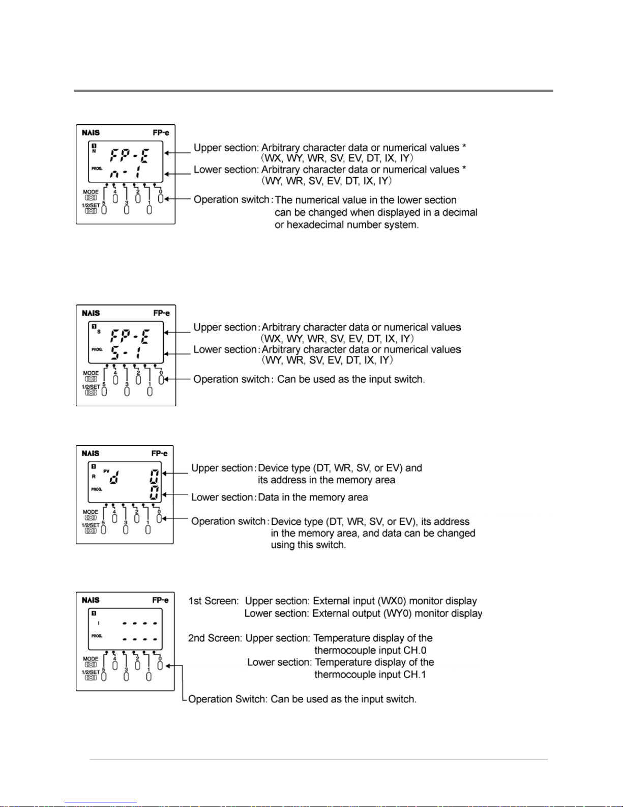
2.2.2 Mode Displays
N (Normal) mode Screen is registered using the F180 (SCR) command.
*Numerical values are displayed only in 16-b it. T he data can be displayed in
a bit, decimal, or hexadecimal system.
S (Switch) mode Screen is registered using the F180 (SCR) command.
R (Register) mode Screen cannot be defined using the F180 (SCR) command.
I (I/O monitor) mode Screen cannot be defined using the F180 (SCR) command.
Phone: 800.894.0412 - Fax: 888.723.4773 - Web: www.clrwtr.com - Email: info@clrwtr.com
2-6
2.3 Input and Output Specifications
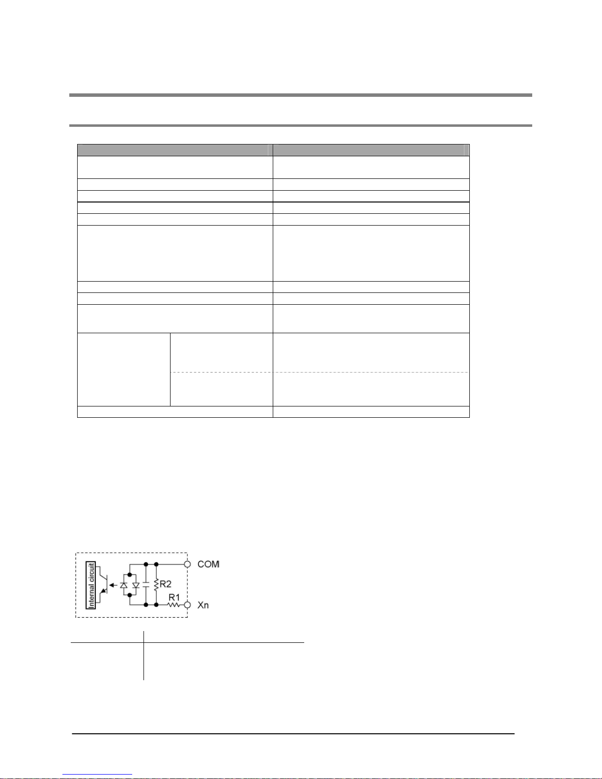
2.3.1 Input specifications
- DC input specifications (X0 toX7)
Item Description
Number of input
8 points
6 points (thermocouple input type)
Insulation method
Optical coupler
Rated input voltage
24 V DC
Operating voltage range
21.6 to 26.4 V DC
Rated input current
Approx. 4.3 mA
Input points per common
8 points/common,
6 points/common (thermocouple input type)
(Either the positive or negative of the input
power supply can be connected to
common terminal.)
ON voltage/ON current
19.2 V or less / 4 mA or less
OFF voltage/OFF current
2.4 V or more / 1 mA or more
Input impedance
Approx. 5.1 kΩ (X0, X1)
Approx. 5.6 kΩ (X2 to X7)
Response time OFF to ON
50 µs or less (X0, X1)
Note)
100 µs or less (X2 to X5)
Note)
2 ms or less (X6, X7)
ON to OFF
50 µs or less (X0, X1)
Note)
100 µs or less (X2 to X5)
Note)
2 ms or less (X6, X7)
Operation indicator
LCD display (I/O monitor mode)
Note) X0 through X5 are inputs for the high-speed counter and have a fast response time. If used as
normal inputs, you are recommend to insert a timer in the ladder program as chattering and
noise may be interpreted as an input signal.
Also, the above specifications apply when the rated input voltage is 24V DC and the temperature
is 25 ºC.
Internal circuit diagram
R
1
R
2
X0 and X1
5.1 kΩ 3 kΩ
X2 to X5
5.6 kΩ 2 kΩ
X6 and X7
5.6 kΩ 1 kΩ
Phone: 800.894.0412 - Fax: 888.723.4773 - Web: www.clrwtr.com - Email: info@clrwtr.com

2-7
- Thermocouple input specifications
Item Specifications
Number of input
2 points (CH0: WX1, CH1: WX2)
Temperature sensor type
Thermocouple type K
Input range
- 30.0 to 300.0 ºC
*1)
(- 22 to 572 ºF)
Accuracy
±0.5%FS±1.5 ºC (FS = -30 to 300 ºC)
Resolution
0.1 ºC
Conversion time
250 ms/2CH
*2)
Insulation method
Between internal circuit and thermocouple input
circuit: noninsulated
*3)
Between CH0 and CH1 of thermocouple input:
PhotoMos insulation
Detection function of wire
disconnection
Available
*1)Temperature can be measured up to 330 ºC (626 ºF). When the measured temper ature exceeds 330
ºC (626 ºF) or the thermocouple wiring is disconnected, “K20000” is written to the register.
*2)Temperature conversion for thermocouple input is performed every 250 ms. The conversion data is
updated on the internal data register after the scan is completed.
*3)The internal circuit and thermocouple input circuit are not insulated. Therefore, use the nongroundi ng
type thermocouples and sheath tubes.
Note:
- To prevent the influence of noise, use the shielded thermocouples and compensating lead wires
after grounding them. When the shielding types are not used, thermocouples and compensating
lead wires should be used less than 10 m.
- When the wire of the thermocouple is extended, be sure to use compensating lead wires
according to the thermocouple type.
- It takes about 2 seconds until the input processing is completed after the power is supplied.
Therefore, the input data is necessary to be valid after the temperature input completion flags X4E
(CH0) and X4F (CH1) turn ON.
After that, the temperature input completion flags turn on for only one scan at every time that the
temperature conversion process has been completed (every 250ms approx).
- 1 to 50 times (Average) can be set using the system register 409. The initial setting is “0.” (Average:
20 times)
Set the value to 20 or more to prevent the fluctuation of the thermocouple input value.
- For accurate temperature measurement, we recommend to warm up the unit for 30 minutes after the
power is supplied.
- Connecting/disconnecting the thermocouple input terminal block while the thermocouple unit is ON
will lower accuracy temporarily. In that case, it is recommended to warm up the unit for at least 15
minutes.
- A rapid temperature change in the thermocouple unit might change the temperature data temporarily.
- Prevent a direct air (wind) from the cooling fan built in the control panel etc. The direct air (wind) to the
thermocouple unit will lower accuracy.
Example of Input temperature and internal data processing
Input temperature Internal data (WX1 and WX2)
- 30.0 ºC (- 22.0 ºF) K-300 (K-220)
25.0 ºC ( 77.0 ºF) K 250 (K 770)
200.0 ºC (392.0 ºF) K2000 (K3920)
To display the temperature in the Fahrenheit scale (ºF), turn Y37 contact ON.
F = C x 9/5 + 32
F: Fahrenheit, C: Celsius, 0 ºC = 32 ºF, 100 ºC = 212 ºF
Phone: 800.894.0412 - Fax: 888.723.4773 - Web: www.clrwtr.com - Email: info@clrwtr.com
2-8
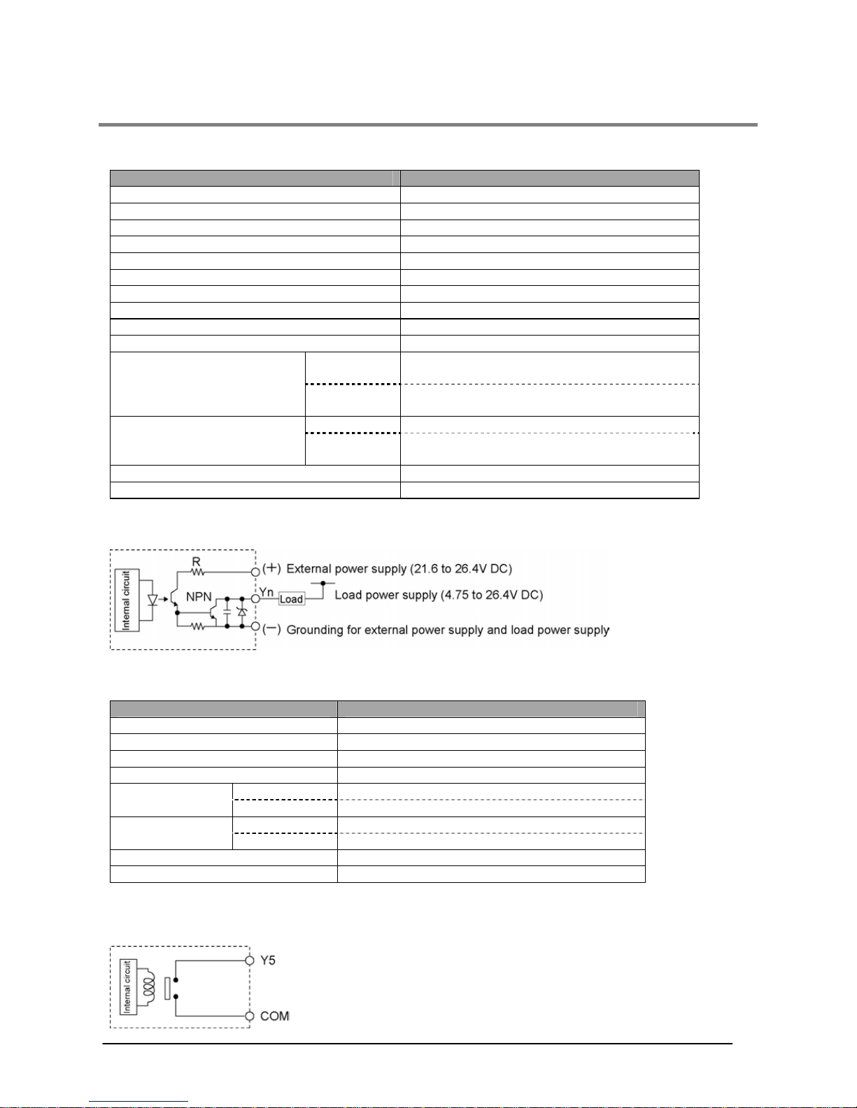
2.3.2 Output specifications
-Transistor output specifications (For Y0 to Y4)
Item Description (NPN)
Number of output
5 points
Insulation method
Optical coupler
Output type
Open collector
Rated load voltage
5 to 24 V DC
Operating load voltage range
4.75 to 26.4 V DC
Max. load current
0.5 A
Max. surge current
1 A
Output points per common
5 points/common
OFF state leakage current
100 µA or less
ON state voltage drop
1.5 V or less
OFF to ON
50 µs or less (For Y0 and Y1)
1 ms or less (For Y2,Y3 and Y4)
Response time
ON to OFF
50 µs or less (For Y0 and Y1)
1 ms or less (For Y2,Y3 and Y4)
Voltage
21.6 to 26.4 V DC
External power supply
(For driving internal circuit)
Current
6 mA/point (For Y0 and Y1)
3 mA/point (For Y2, Y3, and Y4)
Surge absorber
Zener diode
Operation indicator
LCD display (I/O monitor mode)
Internal circuit diagram
- Relay output specifications (Y5)
Item Description
Number of output
1 point
Output type
Normally open (1 Form A)
Rated control capacity
2 A 250 V AC, 2 A 30 V DC
Note1)
Output points per common
1point/common
OFF to ON
Approx. 10 ms
Response time
ON to OFF
Approx. 8 ms
Mechanical
Min. 20,000,000 operations
Life time
Electrical
Min. 100,000 operations (resistive load)
Note2)
Surge absorber
None
Operation indicator
LCD display (I/O monitor mode)
Note1) Resistance load
Note2) Open/Close frequency: 20 times/min (at the rated control capacity)
Internal circuit diagram
Phone: 800.894.0412 - Fax: 888.723.4773 - Web: www.clrwtr.com - Email: info@clrwtr.com
2-9
2.4 Display/Front Operation Switch Specifications
- Display section specifications
Item Description
Data display
5 digits with a decimal point. (Minus sign can also be used.)
Note)
7-segment, color selectable display (Green, red, or orange)
Mark display
PV SV (Green, red, or orange)
● ºF ºC h m s (Green)
Display mode
4 modes (Green)
N : Normal mode---Simple characters, data display,
data setting/data input switch
S : Switch mode----Simple characters, data setting/PLC external
input switch
R : Register mode---Internal data, timer/counter value reading
and writing modes
I : I/O monitor mode---I/O status display/PLC external input switch
Screen No.
(Green)
Status display
LOCK, RUN and PROG. (Green) ERR ALARM (Red)
Switch input
8 points For mode switching 1 point
For screen switching 1 point
For data setting or external input 6 points
*Refer to the input address (below) for external input.
Display
Negative backlight LCD
(Colors in the numerical section can be changed: green, red, or orange
Size of the
characters
7-segment 6.7 mm LOCK
PV SV 1.6 mm ERR 1.4 mm
N S R I 1.7 mm ALARM
● ºF ºC h m s 1.6 mm
Note: Numerical values are displayed only in 16-bit. T he data can be disp layed in a bit, decimal, or
hexadecimal system.
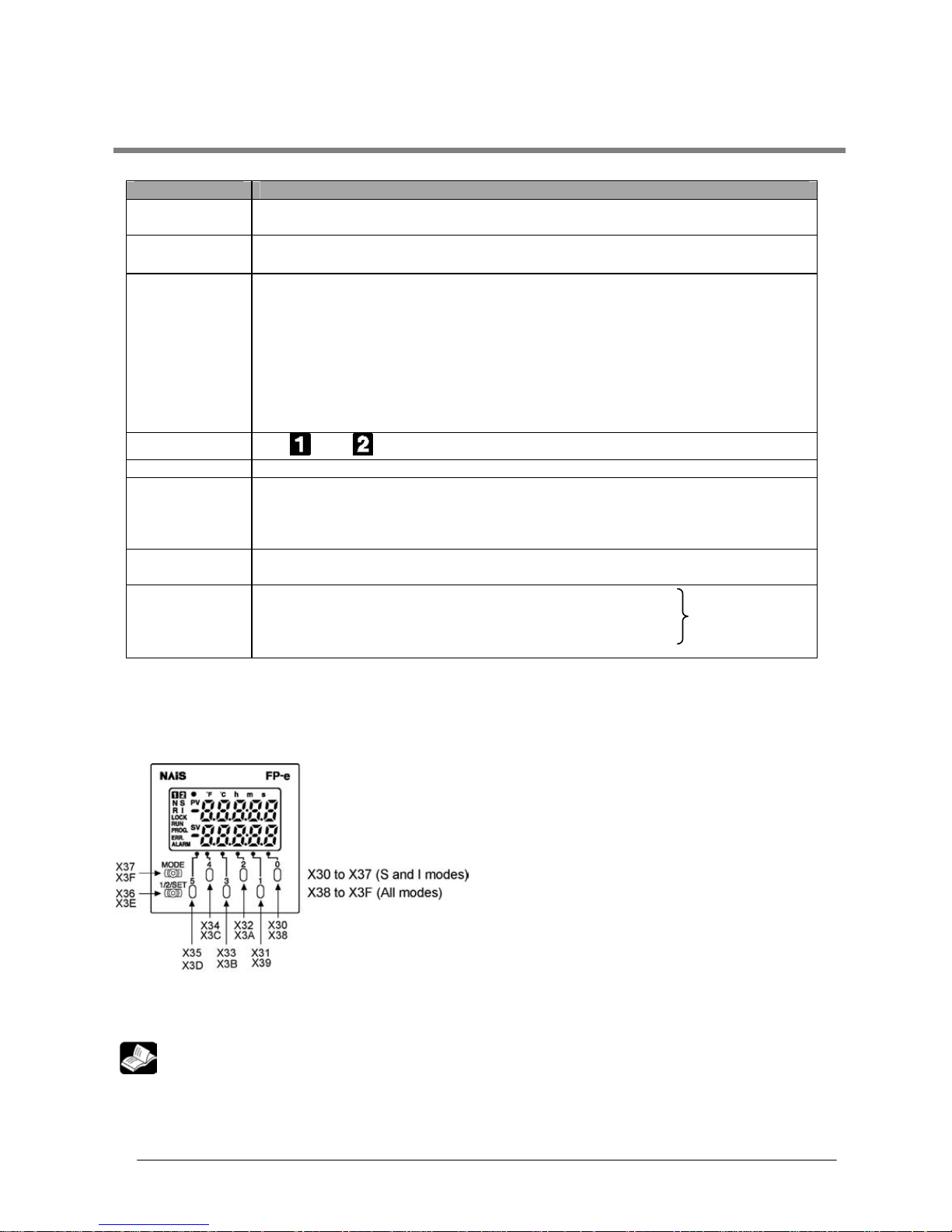
- Front operation switch (External input address)
When the front operation switch is used for external input, use the allocated addresses as shown below.
Example: When “0” is pressed during the S mode, “X30” and “X38” turn ON at the same time.
Reference: A.2 I/O allocation
Phone: 800.894.0412 - Fax: 888.723.4773 - Web: www.clrwtr.com - Email: info@clrwtr.com
2-10
2.5 Calendar timer
2.5.1 Area for calendar timer
With the clock/calendar function, data indicating the hour, minute, second, day, year
and other information stored in the special data registers DT9053 to DT9057 can be
read using the transmission instruction and used in sequence programs.
Special data
Register No.
Upper byte Lower byte Reading Writing
DT9053 Hour data
H00 to H23
Minute data
H00 to H59
Available Not available
DT9054 Minute data
H00 to H59
Second data
H00 to H59
Available Available
DT9055 Day data
H01 to H31
Hour data
H00 to H23
Available Available
DT9056 Year data
H00 to H99
Month data
H01 to H12
Available Available
DT9057
—
Day- of - theweek data
H00 to H06
Available Available
Note:
1. The area above is available for the FP-e unit with a calendar timer function.
2. The value is not fixed initially when the battery is connected. Set the appropriat e valu e to the calendar
timer.
Lithium battery is included in the FP-e unit, but it is not connected to the unit. Connect the battery to the
unit before using the FP-e controller.
3. Put in a new battery within a minute after removing the old battery.
4. A calendar timer is available only when a battery is installed.
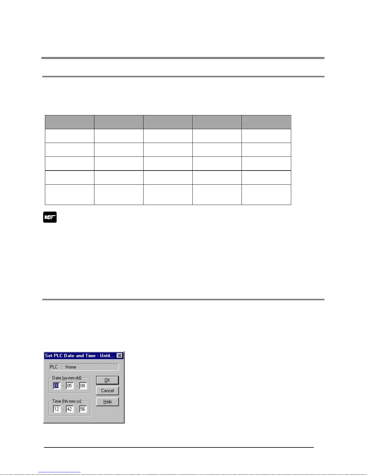
2.5.2 Setting of calendar timer function
There are two ways to set the calendar timer function as described below.
- Setting using FPWIN GR
1. Press the [CTRL] and [F2] keys at the same time, to switch the screen to [Online].
2. Select “Set PLC Date and Time” under “Tool” on the menu bar.
PLC Date and Time setting dialog box
The above steps display the “Set PLC Date and
Time dialog box” shown on the left. Input the date and time, and
click on the “OK” button.
Phone: 800.894.0412 - Fax: 888.723.4773 - Web: www.clrwtr.com - Email: info@clrwtr.com
2-11
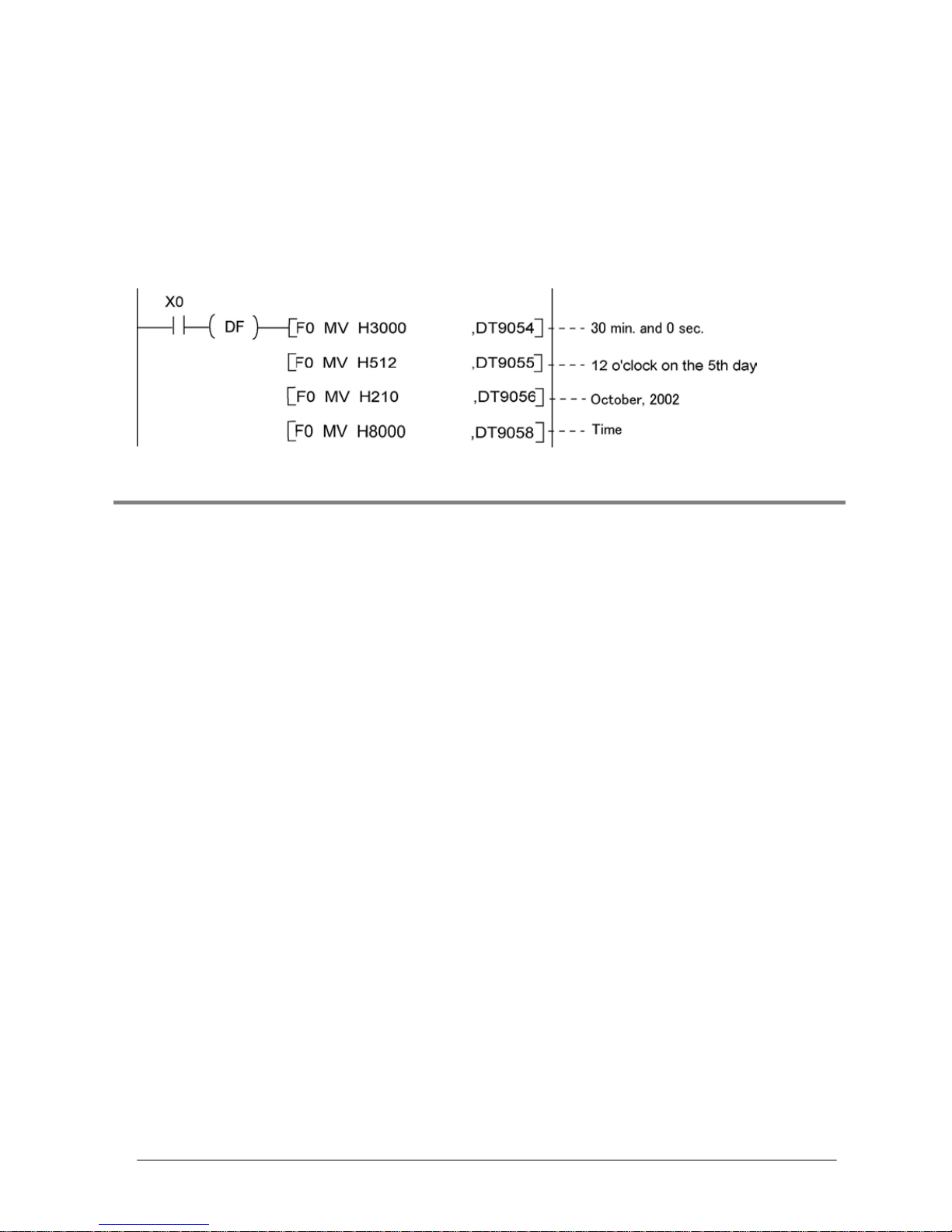
- Setting and changing using program
1. The values written to the special data registers DT9054 to DT9057, which are allocated as the calendar
timer setting area, are transferred.
2. A value of H8000 is written to DT9058.
Example: showing the date and time being written
Set the time to 12:30:00 on the 5
th
day of October, 2002 when the X0 turns ON.
2.5.3 Accuracy of calendar timer
Accuracy
200 s / month (0 ºC)
70 s / month (25 ºC)
240 s /month (55 ºC)
Phone: 800.894.0412 - Fax: 888.723.4773 - Web: www.clrwtr.com - Email: info@clrwtr.com
2-12
2.6 Limitations in data hold/non-hold function
Setting a system register can expand the data hold area. In this case, however, a back-up battery must be
previously installed.
Product No. Settings
Note 1
Data
AFPE224300
AFPE224302
AFPE224322
Note 2
System register setting Non-hold
System register setting with a back-up battery Hold AFPE224305
AFPE214325
System register setting without a back-up battery Non-hold
Note 1: System register settings are effective only when a back-up battery is installed in
the FP-e control unit.(A set value will be returned to the default value.)
Note 2: A back-up battery cannot be installed in this type of product.
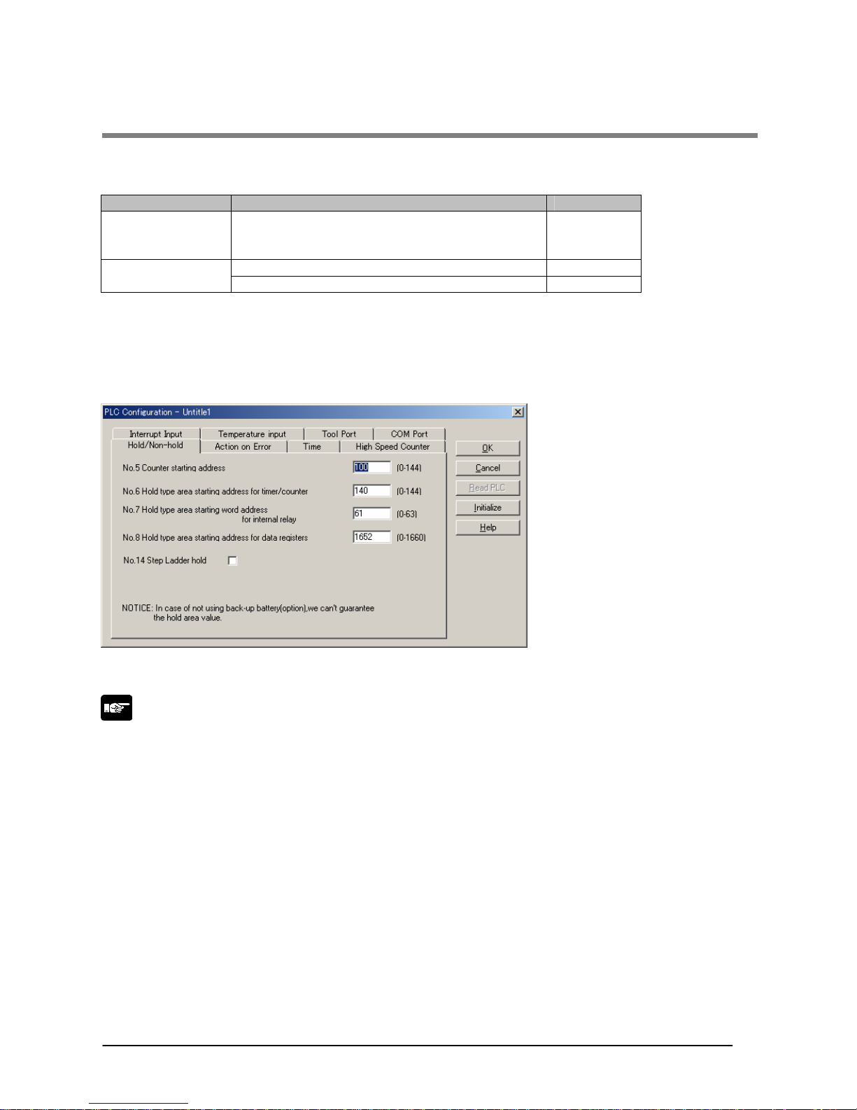
System register setting screen – (Hold/Non-hold)
Areas for Nos. 6, 7, 8 and 14 can be expanded.
Note: “NOTICE” in the screen above is described for the FPWIN GR Ver. 2.24 or higher.
Note: System register initial values on Hold/Non-hold tab are within the ones that can be backed up
with a ROM.
Phone: 800.894.0412 - Fax: 888.723.4773 - Web: www.clrwtr.com - Email: info@clrwtr.com

3-1
Chapter 3
Installation and Wiring
Phone: 800.894.0412 - Fax: 888.723.4773 - Web: www.clrwtr.com - Email: info@clrwtr.com

3-2
3.1 Installation
3.1.1 Operating environment
Avoid mounting the unit in the following locations:
-Ambient temperatures outside the range of 0 ºC to 55 ºC.
-Ambient humidity outside the range of 30 % to 85 %RH (at 25 ºC, non-condensing).
-Sudden temperature changes causing condensation
-Corrosive and inflammable gases
-Excessive airborne dust, metal particle, or salts
-Benzine, thinner, alcohol or other organic solvents, or strong alkaline solutions such as ammonia or
caustic soda
-Excessive vibration or shock
-Direct sunlight
-Water, oil, or chemicals in any form including spray or mist
Measures regarding noise:
-The unit should be installed apart from the high voltage cables, high voltag e equipment, power cables,
power equipment, or any other equipment that would generate high switching surges.
-The unit should also be installed apart from the devices which have radio transmitters.
-If noise occurs in the power supply line even after the above countermeasures are taken, you are
recommended to supply power through an insulation transformer, noise filter, or like.
Measures regarding heat discharge:
-Always amount the unit oriented with the LCD facing upward in order to prevent the generation of heat.
Do not amount the units vertically as shown below.
-Do not install the unit as shown below.
-Do not amount the unit above which generate large heat such as heaters, transformers, or large scale
resisters.
Note that the ambient temperature and electrical voltage are restricted when the mounting panel is
installed at the angle of 0 (horizontal) to 60.
Phone: 800.894.0412 - Fax: 888.723.4773 - Web: www.clrwtr.com - Email: info@clrwtr.com
3-3
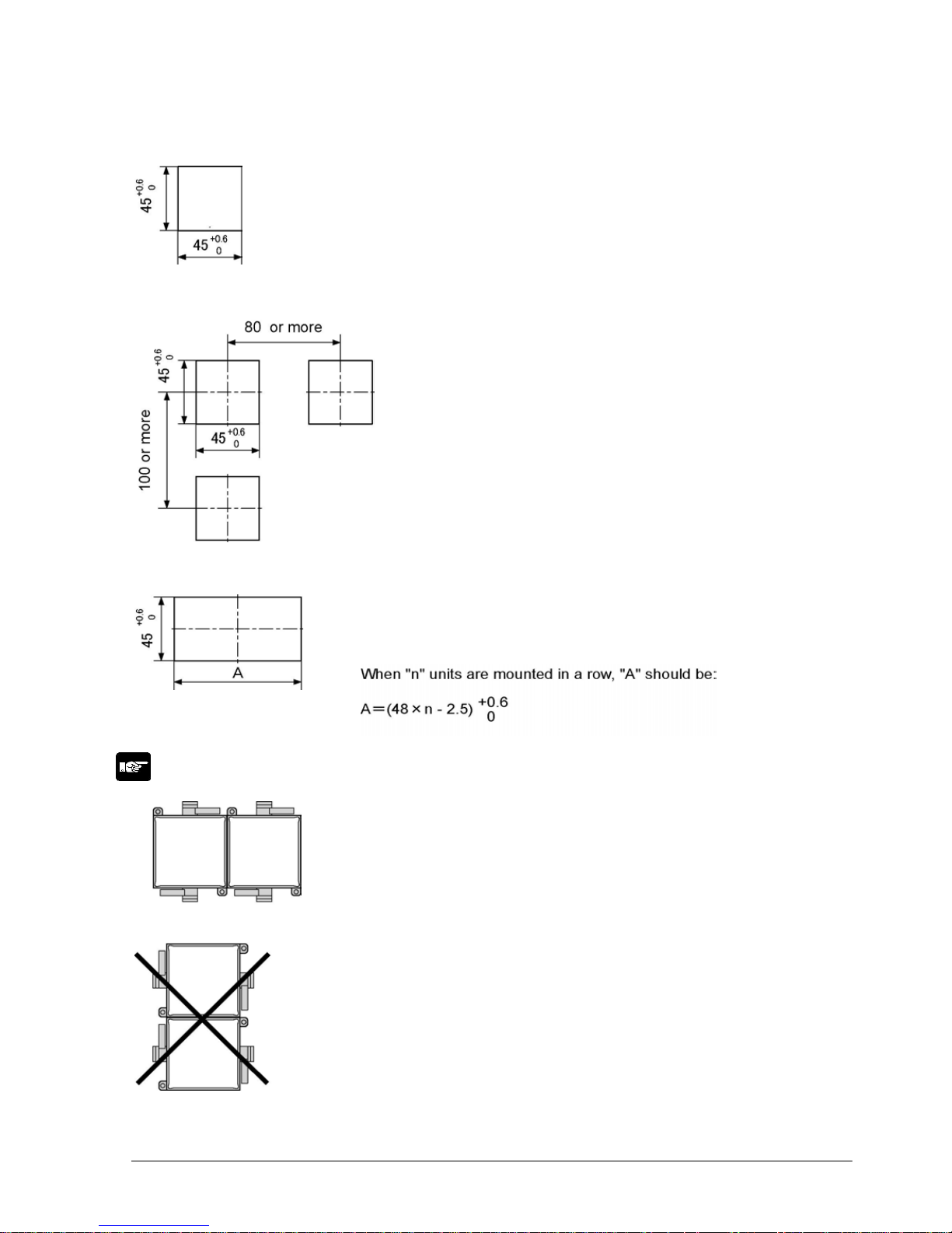
Mounting panel cut size (Unit: mm)
- Standard mounting panel cut size
Mounting panel cut size is shown in the diagram on
the left.
(Panel thickness: 1 to 5 mm)
-When using two or more units:
Make holes in the specified size as shown in
the diagram on the left.
-When mounting units in a row
Units can be mounted horizontally in a row. In that
case, however, waterproofing property on the unit will
be lost.
Note: When mounting the units horizontally in a row:
Mount the units oriented with the molded spring
sections of the mounting flame facing upward
and downward.
Do not mount the units vertically in a row in
order to prevent the generation of heat.
Phone: 800.894.0412 - Fax: 888.723.4773 - Web: www.clrwtr.com - Email: info@clrwtr.com
3-4
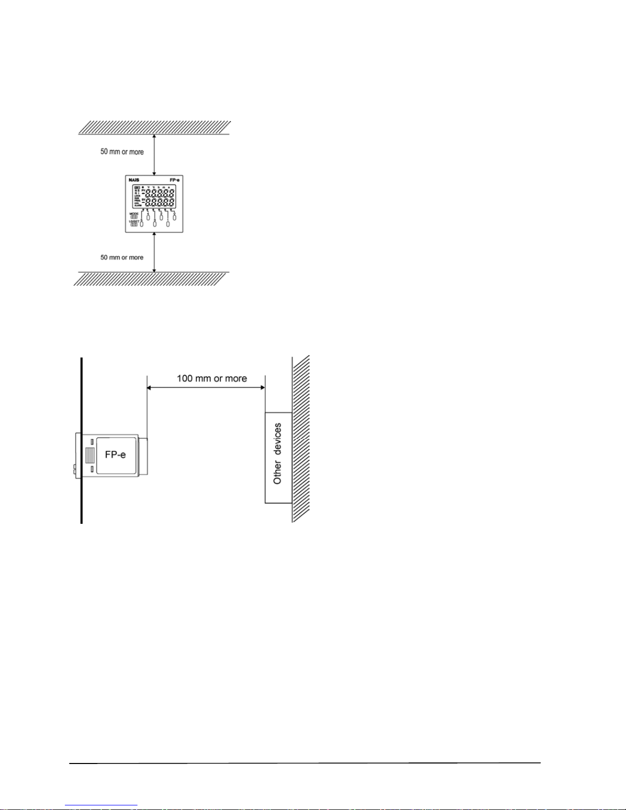
Installation space
- Leave at least 50 mm of space between the wiring ducts of the unit and other devices to allow heat
radiation and unit replacement.
- Maintain 100 mm or more space between the unit and other devices in order to allow room for
programming tool connections and wiring, or to avoid radiated noise and heat from other devices.
Phone: 800.894.0412 - Fax: 888.723.4773 - Web: www.clrwtr.com - Email: info@clrwtr.com
 Loading...