

Panasonic AFP7MC16EC, FP7, AFP7MC32EC, AFP7MC64EC User Manual

Safety Precautions
Observe the following notices to ensure personal safety or to prevent accidents.
To ensure that you use this product correctly, read this User’s Manual thoroughly before use.
Make sure that you fully understand the product and information on safety.
This manual uses two safety flags to indicate different levels of danger.
WARNING
If critical situations that could lead to user’s death or serious injury is assumed by
mishandling of the product.
-Always take precautions to ensure the overall safety of your system, so that the whole
system remains safe in the event of failure of this product or other external factor.
-Do not use this product in areas with inflammable gas. It could lead to an explosion.
-Exposing this product to excessive heat or open flames could cause damage to the lithium
battery or other electronic parts.
CAUTION
If critical situations that could lead to user’s injury or only property damage is
assumed by mishandling of the product.
-To prevent excessive exothermic heat or smoke generation, use this product at the values
less than the maximum of the characteristics and performance that are assured in these
specifications.
-Do not dismantle or remodel the product. It could cause excessive exothermic heat or smoke
generation.
-Do not touch the terminal while turning on electricity. It could lead to an electric shock.
-Use the external devices to function the emergency stop and interlock circuit.
-Connect the wires or connectors securely.
The loose connection could cause excessive exothermic heat or smoke generation.
-Do not allow foreign matters such as liquid, flammable materials, metals to go into the inside
of the product. It could cause excessive exothermic heat or smoke generation.
-Do not undertake construction (such as connection and disconnection) while the power
supply is on. It could lead to an electric shock.
Copyright / Trademarks
-This manual and its contents are copyrighted.
-You may not copy this manual, in whole or part, without written consent of
Industrial Devices SUNX Co., Ltd.
-Windows is a registered trademark of Microsoft Corporation in the United States and other
countries.
-EtherCAT is registered trademark and patented technology, licensed by Beckhoff
Automation Gmbh, Germany.
-All other company names and product names are trademarks or registered trademarks of
their respective owners.
Panasonic
PLC_EC

Introduction
Unit name or purpose of use
Manual name
Manual code
Thank you for buying a Panasonic product. Before you use the product, please carefully read
the installation instructions and the users manual, and understand their contents in detail to
use the product properly.
Types of Manual
• There are different types of users manual for the FP7 series, as listed below. Please refer to
a relevant manual for the unit and purpose of your use.
• The manuals can be downloaded on our website:
http://industrial.panasonic.com/ac/e/dl_center/manual/
FP7 Power Supply Unit
FP7 CPU Unit
Instructions for Built-in
LAN Port
FP7 Web Server Function Manual See our web site.
Instructions for Built-in
COM Port
FP7 Extension Cassette
(Communication)
(RS-232C/RS485 type)
FP7 Extension Cassette
(Communication)
(Ethernet type)
FP7 Extension (Function)
Cassette
Analog Cassette
FP7 Digital Input/Output Unit FP7 Digital Input/Output Unit Users Manual WUME-FP7DIO
FP7 Analog Input Unit FP7 Analog Input Unit Users Manual WUME-FP7AIH
FP7 Analog Output Unit FP7 Analog Output Unit Users Manual WUME-FP7AOH
Thermocouple Multi-analog
Input Unit
RTD input unit
FP7 Multi Input/Output Unit FP7 Multi Input/Output Unit Users Manual WUME-FP7MXY
FP7 High-speed Counter Unit FP7 High-speed Counter Unit Users Manual WUME-FP7HSC
FP7 CPU Unit Users Manual (Hardware) WUME-FP7CPUH
FP7 CPU Unit Command Reference Manual WUME-FP7CPUPGR
FP7 CPU Unit Users Manual
(Logging Trace Function)
FP7 CPU Unit Users Manual (Security Function) WUME-FP7CPUSEC
FP7 CPU Unit Users Manual
(LAN Port Communication)
FP7 CPU Unit User's Manual (EtherNetIP
Communication)
FP7 CPU Unit Users Manual (EtherNet IP
communication)
FP7 series Users Manual (SCU communication) WUME-FP7COM
FP7 series Users Manual (Communication
cassette Ethernet type)
FP7 Analog Cassette Users Manual WUME-FP7FCA
Thermocouple Multi-analog Input Unit
RTD Input Unit
Users Manual
WUME-FP7CPULOG
WUME-FP7LAN
WUME-FP7CPUETEX
See our web site.
WUME-FP7CCET
WUME-FP7TCRTD
i

Types of Manual
Unit name or purpose of use
Manual name
Manual code
FP7 Pulse Output Unit FP7 Pulse Output Unit Users Manual WUME-FP7PG
FP7 Positioning Unit FP7 Positioning Unit Users Manual WUME-FP7POSP
FP7 Serial Communication
Unit
PHLS System PHLS System Users Manual WUME-PHLS
Programming Software
FPWIN GR7
FP7 series Users Manual (SCU communication) WUME-FP7COM
FPWIN GR7 Introduction Guidance WUME-FPWINGR7
ii

Glossary
To make explanations simple, abbreviations are used for the following terms.
Abbreviation Name Description
FP7 MC Unit FP7 Motion Control Unit The product name of the unit described in this manual.
CMI
As for the following terms, they are expressed differently in software, manuals and
specification concerning FP7 MC Unit and Servo Amplifier A5B.
FP7 MC Unit A5B Description
Station address Station alias
-
General-purpose
input
- General-purpose output
General-purpose
output
Control Motion
Integrator
General-purpose
monitor input
-
-
The software for stting parameters of FP7MC Unit.
This shows the unit numbers allocated to slaves on
EtherCAT network. The left two terms have the same
meaning.
Five inputs of symbols SI-MON1 to SI-MON5 are allocated
on the A5B side.
On the FP7 MC Unit side, eight signals of A5B are treated
as "general-purpose input" and can be monitored through
the unit memory.
NOT, POT, HOmE, SI-MON1 to SI-MON5
For using it in combination with FP7 MC Unit, SI-MON3 and
SI-MON4 are used as limit inputs. NOT and POT are not
used.
On the A5B side, one input of symbol EX-OUT1 is
allocated.
On the FP7 MC Unit side, one signal to A5B are treated as
"general-purpose output" and can be written through the
unit memory.
EX-OUT1
Glossary
iii

Table of Contents
Table of Contents
1. Unit Functions and Restrictions ....................................... 1-1
1.1 Functions of Motion Control ................................................................... 1-2
1.1.1 Functions of Unit ..................................................................................... 1-2
1.1.2 List of Models .......................................................................................... 1-3
1.2 Restrictions............................................................................................ 1-4
1.2.1 Supported Functions ............................................................................... 1-4
1.2.2 Restrictions by Power Consumption in FP7 System ............................... 1-5
1.2.3 Applicable Versions of FPWINGR7 and FP7 Units ................................. 1-5
1.3 System Configuration ............................................................................ 1-6
1.3.1 Example of System Configuration ........................................................... 1-6
1.3.2 Type of Software ..................................................................................... 1-7
1.4 Mechanism of Processing ...................................................................... 1-8
1.4.1 Schematic View ....................................................................................... 1-8
1.4.2 Operation When Powe Supply Turns On ................................................ 1-9
1.4.3 Start/Stop by User Programs .................................................................. 1-9
2. Names and Functions of Parts ......................................... 2-1
2.1 Names and Functions of Parts............................................................... 2-2
2.1.1 Names and Functions of Parts ................................................................ 2-2
2.1.2 Operation monitor LEDs .......................................................................... 2-3
2.1.3 ESM (State Transition Diagram) ............................................................. 2-4
3. Installation and Wiring ...................................................... 3-1
3.1 Settings of Servo Amplifier A5B ............................................................. 3-2
iv

Table of Contents
3.1.1 Checking Rotary Switches ...................................................................... 3-2
3.1.2 Connection of Input Signals .................................................................... 3-3
3.2 Connection of Network .......................................................................... 3-4
3.2.1 Wiring ...................................................................................................... 3-4
3.2.2 Precautions on Wiring ............................................................................. 3-4
4. Basic Procedure ................................................................. 4-1
4.1 Section Details ...................................................................................... 4-2
4.2 Registration in I/O Map ......................................................................... 4-3
4.2.1 Creation of I/O map ................................................................................. 4-3
4.2.2 Download of I/O map .............................................................................. 4-4
4.2.3 Storage of I/O map .................................................................................. 4-4
4.2.4 Confirmation of I/O Allocation ................................................................. 4-4
4.2.5 Confirmation of Slot Numbers ................................................................. 4-5
4.3 Setting of Used Axes............................................................................. 4-6
4.3.1 Registration of Used Axes ....................................................................... 4-6
4.4 Setting of Network Configuration ......................................................... 4-10
4.4.1 Registration of Slaves (Offline) ............................................................. 4-10
4.4.2 Registration of Slaves (Online) ............................................................. 4-12
4.4.3 Setting of Station Addresses and Axis Numbers .................................. 4-14
4.4.4 Download to FP7 MC Unit ..................................................................... 4-16
4.4.5 Restarting Power Supplies and Checking Communication State ......... 4-18
4.5 Connection of Limit and Near Home Switches .................................... 4-20
4.5.1 Connection of Input Signals .................................................................. 4-20
4.5.2 Pin Assignment Setting of Servo Amplifier ........................................... 4-21
4.5.3 Checking Servo Amplifier Input State ................................................... 4-23
4.5.4 Settings of FP7 MC Unit ........................................................................ 4-24
4.5.5 Download to FP7 MC Unit ..................................................................... 4-25
4.5.6 Checking Input State ............................................................................. 4-25
4.6 Saving and Managing Files ................................................................. 4-26
4.6.1 File Type ................................................................................................ 4-26
v

Table of Contents
4.6.2 Saving as CMI Files .............................................................................. 4-26
4.6.3 Export to CSV Files ............................................................................... 4-27
5. Settings of FP7 MC Unit .................................................... 5-1
5.1 MC Common Settings ........................................................................... 5-2
5.1.1 MC Common Settings Dialog Box ........................................................... 5-2
5.1.2 MC Common Settings Parameters ......................................................... 5-3
5.2 Axis Parameter Settings ........................................................................ 5-5
5.2.1 Setting by CMI ......................................................................................... 5-5
5.2.2 Axis Parameters (Basic Setup) ............................................................... 5-6
5.2.3 Axis Parameters (Options) ...................................................................... 5-7
5.2.4 Axis Parameters (Operation) ................................................................... 5-8
5.3 Positioning Table Setting ..................................................................... 5-10
5.3.1 Construction of Positioning Tables ........................................................ 5-10
5.3.2 Operation Patterns and Tables ............................................................. 5-13
5.4 Synchronous Parameter and Cam Pattern Settings ............................. 5-14
5.4.1 Synchronous Parameter Settings ......................................................... 5-14
5.4.2 Cam Pattern Setting .............................................................................. 5-15
5.5 Confirmation of Setting Contents ......................................................... 5-16
5.5.1 Check on Parameter Data ..................................................................... 5-16
5.5.2 Comparison of Parameter Information .................................................. 5-16
5.6 Transfer of Parameters ........................................................................ 5-18
5.6.1 Writing Parameters to Unit .................................................................... 5-18
6. Data Transfer to MC Unit and Test Operation .................. 6-1
6.1 Before Turning On the Power ................................................................ 6-2
6.2 Procedure for Turning On the Power ..................................................... 6-3
vi
6.2.1 Procedure for Turning On the Power ...................................................... 6-3
6.2.2 Procedure for Turning Off the Power ...................................................... 6-3

Table of Contents
6.3 Checking While the Power is ON .......................................................... 6-4
6.3.1 Items to Check When the Power is ON................................................... 6-4
6.3.2 Checking Network Communication State ............................................... 6-5
6.3.3 Checking the safety circuit by the PLC unit ............................................ 6-6
6.3.4 Checking the Operation of Near Home Switch ....................................... 6-7
6.3.5 Checking Rotating and Moving Directions and Moving Distance ........... 6-7
6.4 Monitor Function of CMI ........................................................................ 6-8
6.4.1 Status Monitor ......................................................................................... 6-8
6.4.2 Data Monitor .......................................................................................... 6-10
6.5 Tool Operation Function of CMI .......................................................... 6-12
6.5.1 Tool Operation Function ........................................................................ 6-12
6.5.2 Serve ON/OFF with Tool Operation Function ....................................... 6-14
6.5.3 JOG Operation with Tool Operation Function ....................................... 6-16
6.5.4 Home Return by Tool Operation Function ............................................ 6-18
6.5.5 Positioning by Tool Operation Function ................................................ 6-20
6.5.6 Teaching by Tool Operation Function ................................................... 6-23
7. Creation of User Programs ................................................ 7-1
7.1 How to Create User Programs .............................................................. 7-2
7.1.1 Basic Configuration of Program .............................................................. 7-2
7.2 Overview of Programs ........................................................................... 7-4
7.2.1 Reading Data From Input Control Area .................................................. 7-4
7.2.2 Servo ON/OFF Control Program ............................................................. 7-5
7.2.3 Start Enabled Program ............................................................................ 7-6
7.2.4 Each Control Programs ........................................................................... 7-6
7.2.5 Writing Data to Output Control Area ....................................................... 7-7
7.3 Precautions On Programming ............................................................... 7-8
7.3.1 Turning Off Power Supply Clears Contents in Unit Memories ................ 7-8
7.3.2 Operation Cannot be Switched Once One Operation Has Started ......... 7-8
7.3.3 Operation When PLC Mode Changes From RUN To PROG. ................ 7-8
vii

Table of Contents
8. Automatic Operation (Position Control) .......................... 8-1
8.1 Basic Operation ..................................................................................... 8-2
8.1.1 Patterns of Position Control..................................................................... 8-2
8.1.2 Setting and Operation of E-point Control ................................................ 8-4
8.1.3 Setting and Operation of P-point Control ................................................ 8-6
8.1.4 Setting and Operation of C-point Control ................................................ 8-8
8.1.5 Setting and Operation of J-point Control ............................................... 8-10
8.2 Interpolation Control ............................................................................ 8-12
8.2.1 Type of Interpolation Control (Two-axis Interpolation) .......................... 8-12
8.2.2 Type of Interpolation Control (Three-axis Interpolation) ....................... 8-14
8.2.3 Setting and Operation of Two-Axis Linear Interpolation ....................... 8-17
8.2.4 Setting and Operation of Two-Axis Circular Interpolation ..................... 8-19
8.2.5 Setting and Operation of Three-Axis Linear Interpolation ..................... 8-21
8.2.6 Setting and Operation of Three-Axis Spiral Interpolation ...................... 8-23
8.3 Repeat Function .................................................................................. 8-25
8.3.1 Overview of Repeat Operation .............................................................. 8-25
8.3.2 Stop Operation During Repeat Operation ............................................. 8-26
8.3.3 Setting and Operation of Repeat ........................................................... 8-27
8.4 Sample Programs ................................................................................ 8-29
8.4.1 Sample Programs (E-point, C-point and C-point Controls) ................... 8-29
8.4.2 Precautions on Programming ................................................................ 8-31
8.5 Rewriting Positioning Data by User Programs ..................................... 8-32
8.5.1 Overview of Function ............................................................................. 8-32
8.5.2 Procedure of Rewriting .......................................................................... 8-33
8.5.3 Sample Program (Rewritign Positioning Tables) .................................. 8-34
9. Automatic Operation (Synchronous Control) .................. 9-1
9.1 Synchronous Control ............................................................................. 9-2
9.1.1 Overview of Synchronous Control ........................................................... 9-2
9.2 Settings for Master and Slave Axes ....................................................... 9-4
viii

Table of Contents
9.2.1 Selection of Master Axis and Settings .................................................... 9-4
9.2.2 Selection of Slave Axes and Settings ..................................................... 9-5
9.2.3 Unit Type and Number of Axes ............................................................... 9-5
9.2.4 Setting by CMI ......................................................................................... 9-6
9.3 Start and Cancel of Synchronous Control ............................................. 9-8
9.3.1 Start and Cancel of Synchronous Control ............................................... 9-8
9.3.2 Precautions When Canceling or Starting Synchronous Control ........... 9-10
9.4 Electronic Gear Function ..................................................................... 9-12
9.4.1 Overview of Electronic Gear Function .................................................. 9-12
9.4.2 Types and Contents of Setting Parameters .......................................... 9-13
9.4.3 Gear Ratio Changes while in Operation................................................ 9-14
9.5 Electronic Clutch Function .................................................................. 9-16
9.5.1 What is Electronic Clutch Function? ..................................................... 9-16
9.5.2 Types and Contents of Setting Parameters .......................................... 9-17
9.5.3 Trigger Types for Electronic Clutch ....................................................... 9-18
9.5.4 Engagement Method of Electronic Clutch ............................................. 9-19
9.6 Electronic Cam Function ..................................................................... 9-20
9.6.1 Overview of Electronic Cam Function ................................................... 9-20
9.6.2 Types and Contents of Setting Parameters .......................................... 9-21
9.6.3 Cam Pattern Setting Method ................................................................. 9-22
10. Manual Operation (JOG Operation) ................................ 10-1
10.1 Setting and Operation of Home Return ............................................... 10-2
10.2 Changing Speed During JOG Operation ............................................. 10-4
10.3 Setting and Operation of JOG Inching Operation ................................ 10-6
10.4 Sample Programs ............................................................................... 10-8
10.4.1 Sample Program (JOG Operation)........................................................ 10-8
10.4.2 Precautions on Programming .............................................................. 10-10
ix

Table of Contents
11. Manual Operation (Home Return) .................................. 11-1
11.1 Types of Home Return ........................................................................ 11-2
11.2 Operation of Home Return ................................................................... 11-8
11.3 Sample Programs .............................................................................. 11-10
11.3.1 Sample Program (Home Return) ........................................................ 11-10
11.3.2 Precautions on Programming .............................................................. 11-12
12. Stop Functions ................................................................ 12-1
12.1 Type of Stop Functions ........................................................................ 12-2
12.1.1 Type of Stop Operations ....................................................................... 12-2
12.1.2 Characteristics of Pause Function ........................................................ 12-4
12.1.3 Stop Operation During Interpolation Control ......................................... 12-4
12.1.4 Stop Operation During Synchronous Control ........................................ 12-4
12.2 Settings Related to Stop Function ....................................................... 12-5
12.2.1 MC Common Settings ........................................................................... 12-5
12.2.2 Axis Parameter ...................................................................................... 12-6
12.3 Operation During Stop ......................................................................... 12-7
13. Supplementary Functions .............................................. 13-1
13.1 Dwell Time........................................................................................... 13-2
13.2 Software Limit ...................................................................................... 13-3
13.3 Auxiliary Output Code and Auxiliary Output Contact ............................ 13-4
13.4 Current Value Update .......................................................................... 13-6
13.5 Home Coordinates ............................................................................... 13-8
13.6 Movement Amount Automatic Check ................................................. 13-10
13.7 Monitor Error (Torque / Actual Speed Judgement)............................. 13-11
x

Table of Contents
13.8 EtherCAT Communication Setting..................................................... 13-12
13.8.1 EtherCAT Configurator ........................................................................ 13-12
13.8.2 Device Editor ....................................................................................... 13-13
13.8.3 Overview of PDO Mapping .................................................................. 13-14
13.8.4 Change of PDO Mapping .................................................................... 13-15
13.9 EC Packet Monitor Function .............................................................. 13-18
13.9.1 Overview of Function .......................................................................... 13-18
13.9.2 Stored Files ......................................................................................... 13-18
13.9.3 How to Set ........................................................................................... 13-19
13.9.4 How to Execute ................................................................................... 13-20
13.9.5 Handling of SD Memory Card ............................................................. 13-20
14. Troubleshooting .............................................................. 14-1
14.1 Errors and Warnings ........................................................................... 14-2
14.1.1 Errors and warnings .............................................................................. 14-2
14.1.2 Checking and Clearing by CMI ............................................................. 14-2
14.1.3 Clearing Errors/Warnings Using User Programs .................................. 14-3
14.1.4 Error and Warning Logs ........................................................................ 14-4
14.2 Error Recovery Process ...................................................................... 14-5
14.2.1 Overview ............................................................................................... 14-5
14.3 Error Code Table ................................................................................ 14-6
14.3.1 System Errors (From 00F0 1000H ........................................................ 14-6
14.3.2 AMP Communication Errors (From 00F0 2000H) ................................. 14-6
14.3.3 Axis Operation Errors (From 00F0 3000H) ........................................... 14-7
14.3.4 Setting Value Errors (From 00F0 4000H) ............................................. 14-9
14.3.5 Synchronous Parameter Setting Errors (From 00F0 5000H) ............. 14-12
14.4 Warning Code Table ......................................................................... 14-15
14.4.1 Unit Warnings (From 00B0 0000H) ..................................................... 14-15
xi

Table of Contents
15. Specifications .................................................................. 15-1
15.1 Specifications ...................................................................................... 15-2
15.1.1 General Specifications .......................................................................... 15-2
15.1.2 Communication Specifications .............................................................. 15-3
15.1.3 Performance Specifications................................................................... 15-4
15.2 I/O Allocation ....................................................................................... 15-6
15.3 Whole Configuration of Unit Memories ................................................ 15-8
15.4 Unit Memories (Input and Output Control Areas) ............................... 15-10
15.4.1 Configuration of Input Control Area ..................................................... 15-10
15.4.2 Configuration of Output Control Area .................................................. 15-11
15.4.3 List of Input Control Area Functions .................................................... 15-12
15.4.4 List of Output Control Area Function ................................................... 15-20
15.5 Unit Memories (Common Area) ......................................................... 15-25
15.5.1 Configuration of Common Area ........................................................... 15-25
15.5.2 Setting Parameter Control Area .......................................................... 15-26
15.5.3 Operation Speed Rate Area ................................................................ 15-26
15.5.4 Axis Group Setting Area ...................................................................... 15-27
15.5.5 Current Value Update Data Area ........................................................ 15-28
15.5.6 Positioning Control Starting Table Number Setting Area .................... 15-29
15.5.7 Positioning Control Area...................................................................... 15-29
15.5.8 Error Annunciation and Clear Area ..................................................... 15-30
15.5.9 Warning Annunciation and Clear Area ................................................ 15-32
15.5.10 Synchronous Control Monitor Area ................................................. 15-34
15.6 Unit Memories (Each Axis Information Area) ..................................... 15-36
15.6.1 Configuration of each axis information area........................................ 15-36
15.6.2 Each Axis Information & Monitor Area ................................................ 15-37
15.7 Unit Memories (Each Axis Setting Area) ............................................ 15-40
15.7.1 Configuration of Each Axis Setting Area ............................................. 15-40
xii
15.7.2 Configuration of Parameter Setting Area ............................................ 15-41
15.7.3 Parameter Setting Area ....................................................................... 15-42
15.7.4 Configuration of Positioning Data Setting Area ................................... 15-48

Table of Contents
15.8 Unit Memories (Synchronous Control Setting Area) .......................... 15-55
15.8.1 Configuration of Synchronous Control Setting Area ........................... 15-55
15.8.2 Sychronous Control Setting Area ........................................................ 15-56
15.8.3 Electronic Gear Setting Area ............................................................... 15-57
15.8.4 Clutch Setting Area ............................................................................. 15-57
15.8.5 Electronic Cam Setting Area ............................................................... 15-59
15.9 Dimensions ....................................................................................... 15-60
xiii

Table of Contents
xiv

1
Unit Functions and
Restrictions
Unit Functions and Restrictions
A5B
A5B A5B
FP7MC
EtherCAT
USB
Control FPWIN GR7
Control Motion Integrator
USB
PANATERM
1.1 Functions of Motion Control
1.1.1 Functions of Unit
Controlling Servo Motor MINAS A5B series through EtherCAT
FP7 Motion Control Unit (hereafter FP7 MC Unit) adopts EtherCAT communication and
controls servo motors. It achieves wiring saving by network connection and high-speed control.
(Note): EtherCAT is a registered trademark of Beckhoff Automation Gmbh in Germany and a technology protected
by a patent.
Setting using dedicated software "Control Motion Integrator"
Dedicated software "Control Motion Integrator" (sold separately) is provided for easily
configuring the setting of EtherCAT communication and parameters of position control.
1-2

1.1 Functions of Motion Control
1.1.2 List of Models
Main unit
Product name Max. number of control axes Product no.
FP7 Motion Control Unit
(Abbreviated name: FP7
MC Unit)
Related software
Product name Application Product no.
Programming software
FPWIN GR7
Software
Control Motion Integrator
Key Unit For installing a USB port (Note 3) AFPSMTKEY
Setup support software
PANATERM
(Note 1): For the latest information on FPWIN GR7 and Control Motion integrator, see the following web site.
http://industrial.panasonic.com/ac/e/fasys/plc/software/fpwingr7/index.jsp
(Note 2): For the latest information on PANATERM, see the following web site.
https://industrial.panasonic.com/ww/products/motors-compressors/fa-motors/ac-servo-motors/minas-a5panaterm
(Note 3): All the functions of Control Motion Integrator can be used free of charge for 60 days after the installation. For
using the "EtherCAT communication setting" function continuously after the elapse of 60 days, the key unit
should be installed.
16 axes/unit AFP7MC16EC
32 axes/unit AFP7MC32EC
64 axes/unit AFP7MC64EC
This software is used for configuring the whole
FP7 system and creating user programs.
This software is used for configuring FP7 MC Unit
and monitoring the state..
EtherCAT communication parameters
Setting of positioning parameters
Setting of positioning tables
This software is used for setting parameters and
monitoring the states of Servo Amplifier A5B
series.
For the latest information,
see our web site.
For the latest information,
see our web site.
For the latest information,
see our web site.
Required files for EtherCAT communication
The setup information (ESI files) required for EtherCAT communication is included in the
installation data of software "Control Motion Integrator".
(Note): ESI (EtherCAT Slave Information)
1-3

Unit Functions and Restrictions
1.2 Restrictions
1.2.1 Supported Functions
FP7 MC Unit is designed in conformity with the specifications and standard of EtherCAT,
however, FP7 MC Unit Ver.1 supports the items listed in the following table only.
Comparison with EtherCAT specifications
Item EtherCAT specifications Supported items by FP7 MC Unit
Transmission
system
Baud rate 100 Mbps Same as on the left.
Trasmission
distance
Transmission
cable
Topology Line, Daisy chain, Star, Tree Daisy chain (without brach)
Max. number of
connected units
Connectable
device
100BASE-TX Same as on the left.
Max. 100 m between nodes Same as on the left.
STP cable, category 5/5e Always use a cable of category 5e or higher.
65535 64
EtherCAT-compatible devices
Panasonic
AC serv motor A5B series
(EtherCAT-compatible type)
Control mode
Control mode of EtherCAT
Cyclic position control mode (csp) Supported
Profile position control mode (pp) Unsupported
Home return position control
mode (hm )
Interpolation position control
mode (ip)
Cyclic speed control mode (csv)
Profile speed control mode (pv)
Cyclic torque control mode (cst)
Profile torque control mode (tq)
Supported function
of A5B
Supported
Unsupported
Supported Unsupported
Supported items by FP7 MC Unit
The cyclic position control mode (csp) is used
when using it in combination with FP7 MC
Unit.
Only the home return position control mode
(Method33/34/37) is supported. The cyclic
position control mode (csp) is used when
using it in combination with FP7 MC Unit.
When using it in combination with FP7 MC
Unit, FP7 MC Unit performs the interpolation
control.
1-4

1.2 Restrictions
1.2.2 Restrictions by Power Consumption in FP7 System
The unit has the following internal current consumption. Make sure that the total current
consumption is within the capacity of the power supply with consideration of all other units
used in combination with this unit.
Name Product no. Consumption current
AFP7MC16EC
FP7 Motion Control Unit
AFP7MC32EC
AFP7MC64EC
180 mA or less
1.2.3 Applicable Versions of FPWINGR7 and FP7 Units
For using FP7 MC Unit, the following versions of FPWIN GR7 and units are required.
Item Applicable versions
Programming tool software
FPWIN GR7
FP7 CPU Unit
Ver.2.12 or later
There is no restriction on the version.
For using the EC packet monitor function of FP7 MC Unit, use FP7 CPU Unit
(Ethernet function- built-in type).
1-5

Unit Functions and Restrictions
1.3 System Configuration
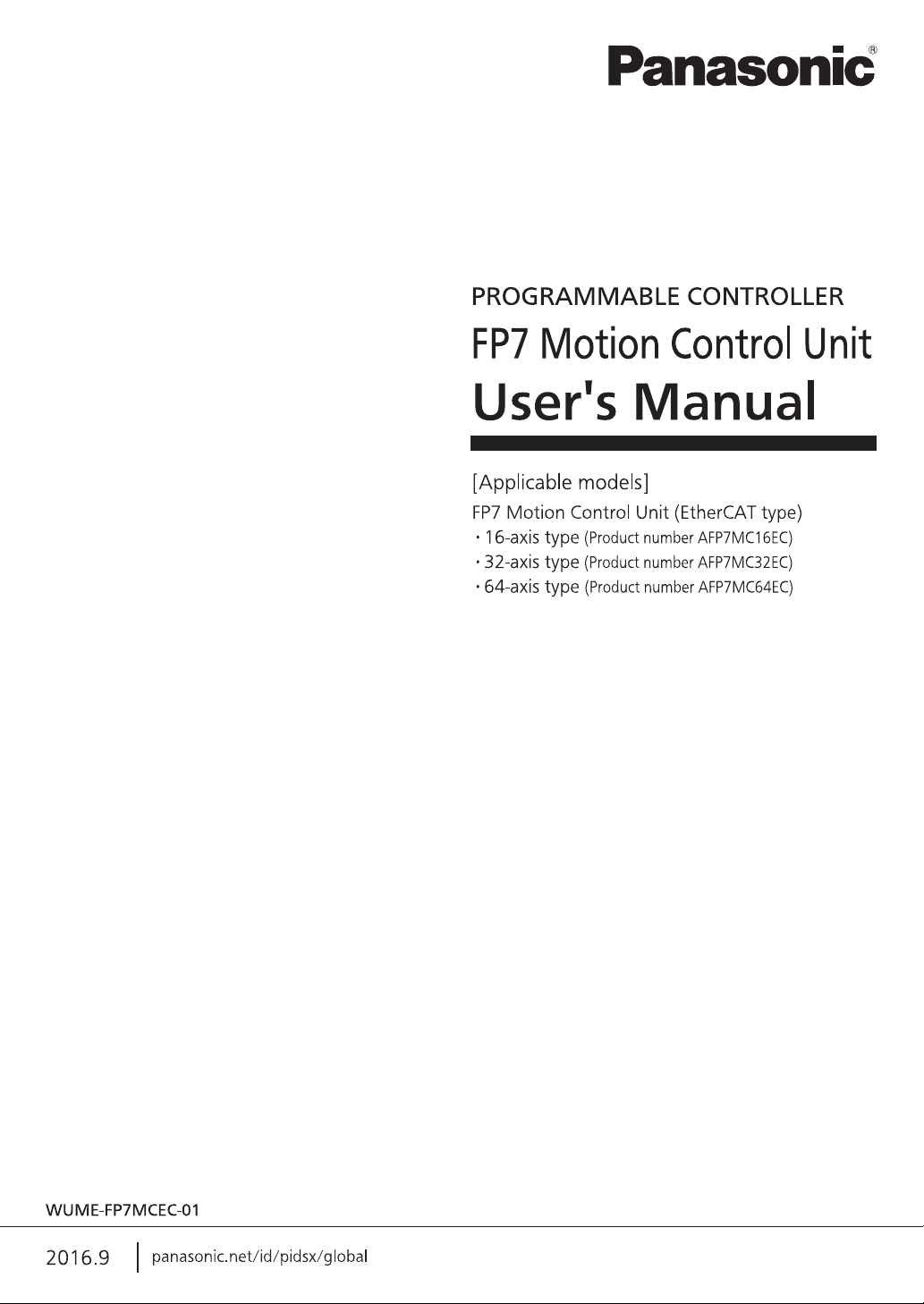
1.3.1 Example of System Configuration
The following figure shows the example of the configuration of one axis when using over limit
switches and a near home switch.
Configuration of devices
No. Item Explanation
The above figure shows the minimum configuration that FP7 CPU Unit,
FP7 MC Unit and an end unit are combined. For FP7 MC Unit, the units
for 16 axes, 32 axes, and 64 axes are available.
FP7 MC Unit and Servo Amplifier A5B are connected with a shielded
twisted pair (STP) cable.
The over limit switches are connected to the servo amplifier. When
using the servo amplifier in combination with FP7 MC Unit, the over
limit switches are connected to the terminals allocated to the generalpurpose monitor inputs of the servo amplifier (SI-MON3/SI-MON4).
The near home switch is connected to the servo amplifier. It is
connected to the terminal allocated to the near home input (HOME).
①
②
③
④
⑤
FP7
Shielded twisted pair (STP)
cable
Servo Amplifier A5B The units of the number of required axes areconnected.
Over limit switch
Near home switch
1-6

1.3 System Configuration
Application:
Application:
Application:
1.3.2 Type of Software
The following three softwares are used for using the system combining FP7 MC Unit and
Servo Amplifier A5B.
Control Motion Integrator Ver.1.0
This software is used for setting parameters of
FP7 MC Unit, monitoring the state and test
operations.
Setting of EtherCAT communication
parameters
Setting of positioning parameters
Setting of positioning tables, etc.
Download destination:
FP7 MC Unit
Connection with the unit:
Connect to the USB port of FP7 CPU Unit.
FPWIN GR7 Ver.2.12
PANATERM Ver.6.0
This software is used for configuring the whole
FP7 system and creating user programs.
Download destination:
FP7 CPU Unit
Connection with the unit:
Connect to the USB port of FP7 CPU Unit.
This software is used for setting parameters
and monitoring the states of Servo Amplifier
A5B series.
Download destination:
Servo Amplifier A5B
Connection with the unit:
Connect to the USB port of Servo Amplifier
A5B.
1-7

Unit Functions and Restrictions
FP7 CPU FP7 MC A5B
FROM
Slave
processing
MC unit
Operation
processing
part
I/O
Y0: System stop
X0: Link establishment
Input
processing
User program
I/O map
● ● ● ● ●
CPU Config.
Power on
EtherCAT
communication
Positioning
parameters
Positioning tables
● ● ● ● ●
Communication
parameters
UM
FPWIN GR7 CMI PANATERM
Update cycle 500μs
-4000μs
Input control area
Output control area
Busy, Done, Error flag
Start, Stop, Servo on/off
UM
Output
processing
1.4 Mechanism of Processing
1.4.1 Schematic View
1-8

1.4 Mechanism of Processing
1.4.2 Operation When Powe Supply Turns On
• FP7 MC Unit reads the "parameters for FP7 MC Unit" stored in the FROM (FlashROM)
within the unit and sets them in the memory areas within the unit.
• FP7 MC Unit starts the communication with the slaves (servo amplifiers) connected to
EtherCAT. Once the links with the slaves (servo amplifiers) are established, it is notified to
FP7 CPU Unit by the input relay (X0).
• When the mode setting switch is set to RUN mode, FP7 CPU Unit checks that the state of
the FP7 system is correct, switches the mode to RUN mode, and executes user programs.
1.4.3 Start/Stop by User Programs
• In the case of FP7 MC Unit, main I/O signals to execute various controls (such as positioning,
JOG operation, home return, and stop) are allocated to the unit memories (UM).
• In the unit memories (UM) "Output control area", request signals to perform stop control are
allocated. In the unit memories "Input control area", flags such as busy flag and error flag to
check the start conditions are allocated.
• FP7 MC Unit controls operations by reading or writing data to these unit memories.
1-9

Unit Functions and Restrictions
1-10

2
Names and Functions of
Parts
Names and Functions of Parts
①
②
③
④
⑤
⑥
⑦
②-a
②-b
②-c
⑥
2.1 Names and Functions of Parts
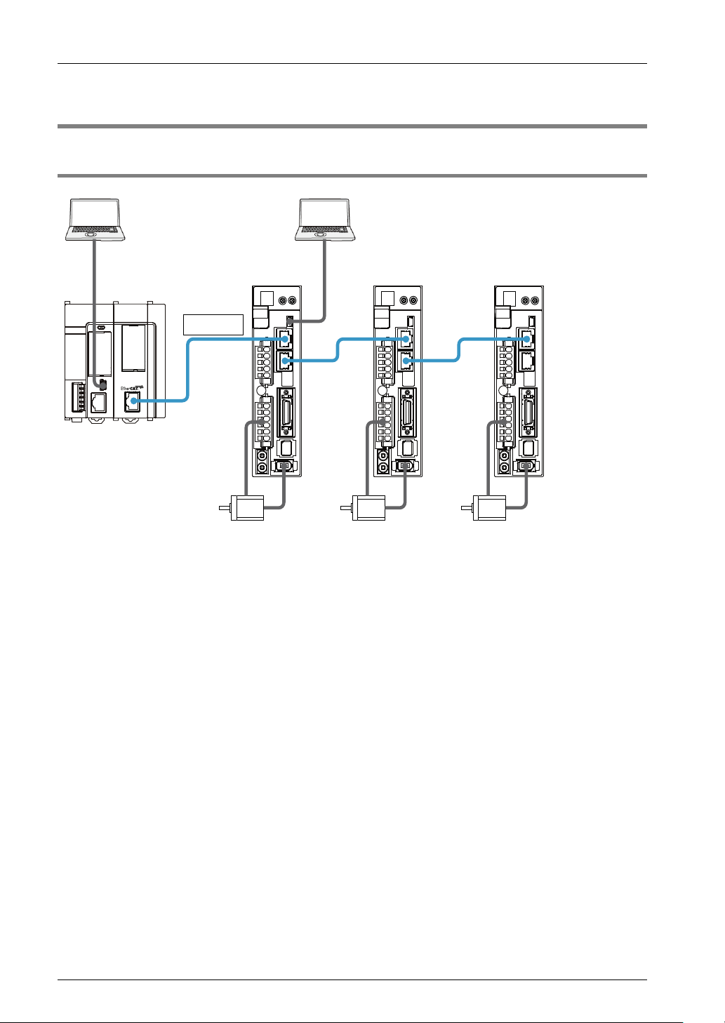
2.1.1 Names and Functions of Parts
Names and functions of parts
No. Name Function
①
②
③
④
⑤
⑥
⑦
Operation monitor
LEDs
Card cover A SD memory card slot is located under the cover.
a: Card slot An SD memory card is inserted.
b: COPY switch
c: Memory selector
switch
Network connector
(RJ45)
DIN hook This hook is used to install the unit on a DIN rail.
Unit connector Connects the internal circuits between units.
Mode setting switch
Fixing hook This hook is used to fix units.
Indicates the state of EtherCAT communication, the occurrence states of
unit's errors and alarms.
This is provided for expansion. Use the switch at the factory default (lower
side) as it is.
This is provided for expansion. Use the switch at the factory default (lower
side) as it is.
This is the connector for connecting to EtherCAT.
This switch is used for the system. Use this at the factory default (no.1-3: ON,
no.4: OFF) as it is.
2-2

2.1.2 Operation monitor LEDs
LED
Color
Status
Description
Blinking
Single flash
Approx.200ms
Approx.1000ms
Approx.200ms
Approx.200ms
2.1 Names and Functions of Parts
- Blue
EC RUN
EC ERR
EC L/A
[SD]
CARD
COPY
ERR
ALM
(Note 1): Blinking and single flash of EC RUN are activated as below.
Green
Red
Green
Green
Green
Green
Red
Red
ON Turns on when the power is supplied to the unit.
OFF INIT state
Blinking Pre-Operational state
Single flash Safe-Operational state
ON Operational state
OFF No error
ON EtherCAT communication error
OFF LINK is not established.
Blinking
ON
ON SD memory card is beng accessed.
OFF Other than the above state.
(Reserved for system)
(Reserved for system)
ON Unit error occurs.
Blinking Unit warnig occurs.
OFF Other than the above states.
ON Unit alarm occurs.
OFF Other than the above state.
LINK is established. Data is
sent/received.
LINK is established. Data is not
sent/received.
Indicates the state of the
ESM (EtherCAT State
Machine) of EtherCAT
communication. Refer to
the next page for details.
Indicates errors in
EtherCAT communication.
Indicates the LINK state of
EtherCAT communication.
2-3

Names and Functions of Parts
Init
Pre-Operational
Safe-Operational
Operational
(IP)
(PI)
(SI)
(SP)
(SO) (OS)
(PS)
(OP)
(OI)
(S→M)
(M→S)
2.1.3 ESM (State Transition Diagram)
Reference: Created by us based on "Operating principle of EtherCAT" issued by ETG
ESM state
(Abbr.)
Init
PreOperational
(PreOP)
SafeOperational
(SafeOP)
Operational
(OP)
(Note): S: Slave, M: Master
communication
Send/Receive
Not available Not available Not available
Available Not available Not available
Available Available Not available
Available Available Available
SDO
PDO
communication
PDO
communication
Description
The state that the
communication part is being
initialized, and data cannot
be sent/received using SDO
(Mailbox) and PDO.
The state that data can be
sent/received using SDO
(Mailbox).
The state that data can be
sent/recevied using SDO
(Mailbox) and data can be
sent (from slaves to master)
using PDO.
The state that data cannot be
sent/received using SDO
(Mailbox) and PDO.
What is ESM (EtherCAT State Machine)?
• ESM shows the state of the communication determined as the specifications of EtherCAT.
• The state transition is performed between FP7 MC Unit and Servo Amplifier A5B, an any
settings or programming by users are not required.
Confirmation method
• The state of ESM can be confirmed by the operation monitor LED "EC RUN" on the front
side of FP7 MC Unit.
• When communication is performed, "Operational (OP)" (EC RUN LED) is ON, and the input
relay (X0 (Link established)" of FP7 MC Unit is ON.
2-4
 Loading...