

Panasonic AFP7CPS4E, AFP7CPS3E, AFP7CCS1, AFP7CCS2, AFP7CCM1 User Manual
...
Phone: 800.894.0412 - Fax: 888.723.4773 - Web: www.clrwtr.com - Email: info@clrwtr.com

Safety Precautions
Phone: 800.894.0412 - Fax: 888.723.4773 - Web: www.clrwtr.com - Email: info@clrwtr.com
Observe the following notices to ensure personal safety or to prevent accidents.
To ensure that you use this product correctly, read this User’s Manual thoroughly before use.
Make sure that you fully understand the product and information on safety.
This manual uses two safety flags to indicate different levels of danger.
WARNING
If critical situations that could lead to user’s death or serious injury is assumed by
mishandling of the product.
-Always take precautions to ensure the overall safety of your system, so that the whole
system remains safe in the event of failure of this product or other external factor.
-Do not use this product in areas with inflammable gas. It could lead to an explosion.
-Exposing this product to excessive heat or open flames could cause damage to the lithium
battery or other electronic parts.
CAUTION
If critical situations that could lead to user’s injury or only property damage is
assumed by mishandling of the product.
-To prevent excessive exothermic heat or smoke generation, use this product at the values
less than the maximum of the characteristics and performance that are assured in these
specifications.
-Do not dismantle or remodel the product. It could cause excessive exothermic heat or smoke
generation.
-Do not touch the terminal while turning on electricity. It could lead to an electric shock.
-Use the external devices to function the emergency stop and interlock circuit.
-Connect the wires or connectors securely.
The loose connection could cause excessive exothermic heat or smoke generat ion.
-Do not allow foreign matters such as liquid, flammable materials, metals to go into the inside
of the product. It could cause excessive exothermic heat or smoke generation.
-Do not undertake construction (such as connection and disconnection) while the power
supply is on. It could lead to an electric shock.
Copyright / Trademarks
-This manual and its contents are copyrighted.
-You may not copy this manual, in whole or part, without written consent of
Industrial Devices SUNX Co., Ltd.
-Windows is a registered trademark of Microsoft Corporation in th e United States and other
countries.
-All other company names and product names are trademarks or registered trademarks of
their respective owners.
Panasonic
PLC_ORG

Introduction
Phone: 800.894.0412 - Fax: 888.723.4773 - Web: www.clrwtr.com - Email: info@clrwtr.com
Thank you for buying a Panasonic product. Before you use the product, please carefully read
the installation instructions and the users manual, and understand their contents in detail to
use the product properly.
Types of Manual
There are different types of user's manual for the FP7 series, as listed below. Please refer to
a relevant manual for the unit and purpose of your use.
The manuals can be downloaded on our website.
Unit name or purpose of
use
FP7 Power Supply Unit
FP7 CPU Unit
ons for Built-in
Instructi
LAN Port
ons for Built-in
Instructi
COM Port
FP7 Extension Cassette
(Communication)
(RS-232C/RS485 type)
FP7 Extension Cassette
(Communication)
(Ethernet type)
FP7 Extension (Function)
Cassette
Analog Cassette
FP7 Digital Input/Output Unit FP7 Digital Input/Output Unit Users Manual WUME-FP7DIO
FP7 Analog Input Unit FP7 Analog Input Unit Users Manual WUME-FP7AIH
FP7 Analog Output Unit FP7 Analog Output Unit Users Manual WUME-FP7AOH
FP7 High-speed counter Unit FP7 High-speed counter Unit Users Manual WUME-FP7HSC
FP7 Pulse Output Unit FP7 Pulse Output Unit Users Manual
FP7 Positioning Unit FP7 Positioning Unit Users Manual WUME-FP7POSP
FP7 Serial Communication
Unit
PHLS System PHLS System Users Manual WUME-PHLS
Programming Software
FPWIN GR7
Manual name Manual code
FP7 CPU Unit Users Manual (Hardware) WUME-FP7CPUH
FP7 CPU Unit Command Reference Manual WUME-FP7CPUPGR
FP7 CPU Unit Users Manual
(Logging Trace Function)
FP7 CPU Unit Users Manual (Security Function) WUME-FP7CPUSEC
FP7 CPU Unit Users Manual
(LAN Port Communication)
FP7 series Users Manual (SCU communication) WUME-FP7COM
FP7 series Users Manual (Communication
cassette Ethernet type)
FP7 Analog Cassette Users Manual
FP7 series Users Manual (SCU communication) WUME-FP7COM
FPWIN GR7 Introduction Guidance WUME-FPWINGR7
WUME-FP7CPULOG
WUME-FP7LAN
WUME-FP7CCET
WUME-FP7FCA
(Upcoming)
WUME-FP7PG
(Upcoming)

Table of Contents
Phone: 800.894.0412 - Fax: 888.723.4773 - Web: www.clrwtr.com - Email: info@clrwtr.com
Table of Contents
1. Functions of Units and Restrictions on Combination.....1-1
1.1 Features and Functions of Units ............................................................ 1-2
1.1.1 Functions of Units....................................................................................1-2
1.1.2 Types of Unit...........................................................................................1-3
1.1.3 Types of Cassette ...................................................................................1-3
1.1.4 Applications that can be Used in Each Port............................................1-3
1.2 Overview of Communication Functions..................................................1-4
1.2.1 PLC Link Functions (MEWNET-W0).......................................................1-4
1.2.2 MEWTOCOL Master/Slave Communication...........................................1-5
1.2.3 MODBUS RTU Master/Slave Communication........................................1-6
1.2.4 General-Purpose Communication...........................................................1-7
1.3 Restrictions on Units Combination.........................................................1-8
1.3.1 Restrictions on the Number of Installed Units.........................................1-8
1.3.2 Restrictions on the Combination of Extension Cassettes (Communication
Cassettes)...............................................................................................1-8
1.3.3 Restrictions on Communication Functions to be Used ...........................1-8
1.3.4 Unit to be Used and Applicable Versions of CPU Unit and FPWIN GR71-8
1.3.5 Restrictions on Consumption Current.....................................................1-9
2. Names and Functions of Parts ..........................................2-1
2.1 Names and Functions of Parts............................................................... 2-2
2.1.1 Communication Port of CPU Unit............................................................2-2
2.1.2 Parts Names and Functions of Serial Communication Unit....................2-3
3. Wiring the COM. Port..........................................................3-1
3.1 Attaching a Communication Cassette....................................................3-2
3.1.1 Attachment Instructions...........................................................................3-2
ii

Table of Contents
Phone: 800.894.0412 - Fax: 888.723.4773 - Web: www.clrwtr.com - Email: info@clrwtr.com
3.2 Wiring of COM Port Terminal Block........................................................3-3
3.2.1 Suitable Wires and Tools........................................................................3-3
3.2.2 Applicable Cable.....................................................................................3-4
3.2.3 Wiring Method.........................................................................................3-5
3.3 Wiring for CPU Unit (GT Power Supply and COM0 Port).......................3-6
3.3.1 Handling of GT Power Supply Terminals................................................3-6
3.3.2 Terminal Layouts and Examples of Wiring .............................................3-6
3.4
Wiring for Communication Cassettes COM.1 to COM.4 Ports...............3-8
3.4.1 Communication Cassette AFP7CCS1 (RS-232C, 1-Channel Insulated
Type).......................................................................................................3-8
3.4.2 Communication Cassette AFP7CCS2 (RS-232C, 2-channel insulated
type) ........................................................................................................3-9
3.4.3 Communication Cassette AFP7CCM1 (RS-422 / RS-485, 1-Channel
Insulated Type) .....................................................................................3-12
3.4.4 Communication Cassette AFP7CCM2 (RS-422 / RS-485, 2-Channel
Insulated Type) .....................................................................................3-15
3.4.5 Communication Cassette AFP7CCS1M1 (RS-232C 1-Channel + RS-485
1-Channel Insulated Type)....................................................................3-19
4. I/O Allocation .......................................................................4-1
4.1 Input/Output Signals Used for Communication.......................................4-2
4.1.1 I/O Allocation of CPU Unit.......................................................................4-2
4.1.2 I/O Allocation of Serial Communication Unit...........................................4-4
4.2 Registration in I/O Map...........................................................................4-6
4.2.1 Settings Using FPWIN GR7 (For CPU with built-in SCU).......................4-6
4.2.2 Settings Using FPWIN GR7 (For Serial Communication Unit) ...............4-6
5. Setting and Confirming Communication Conditions.......5-1
5.1 Setting Applications and Communication Conditions.............................5-2
5.1.1 Applications to be Set for Each Port .......................................................5-2
5.1.2 Conditions to be Set for Each Port..........................................................5-2
iii

Table of Contents
Phone: 800.894.0412 - Fax: 888.723.4773 - Web: www.clrwtr.com - Email: info@clrwtr.com
5.2 Setting Communication Conditions........................................................5-3
5.2.1 Settings Using FPWIN GR7 (For CPU with built-in SCU).......................5-3
5.2.2 Settings Using FPWIN GR7 (For Serial Communication Unit) ...............5-4
6. PLC Link...............................................................................6-1
6.1 Operation of PLC link MEWNET-W0...................................................... 6-2
6.1.1 Overview of PLC Link Operation.............................................................6-2
6.1.2 Operation of Link Relays and Link Registers..........................................6-3
6.2 Configuration Required for PLC Link...................................................... 6-4
6.2.1 Setup Procedure (For CPU with built-in SCU)........................................6-4
6.2.2 Setup Procedure (For Serial Communication Unit).................................6-5
6.2.3 List of Setting Items.................................................................................6-6
6.3 Setting Items for PLC Link...................................................................... 6-7
6.3.1 Station No. Setting ..................................................................................6-7
6.3.2 Max. Station No. Setting..........................................................................6-7
6.3.3 Memory Block Numbers for Link Relays and Link Registers to be Used6-8
6.3.4 Range of Use of Link Relays and Range of Use of Link Registers ........6-8
6.3.5 Starting No. for Link Relay Send Area and Sending Size.......................6-9
6.3.6 Starting No. for Link Register Send Area and Sending Size.................6-10
6.4 PLC Link Response Time..................................................................... 6-12
6.4.1 Response Time of 1 Transmission Cycle..............................................6-12
6.4.2 Response Time When There is a Station Yet to be Added ..................6-14
7. MEWTOCOL Master/Slave Communication...................... 7-1
7.1 Configuration.......................................................................................... 7-2
7.1.1 Setting Communication Conditions.........................................................7-2
7.2 List of MEWTOCOL / MEWTOCOL7 Supporting Commands................ 7-3
7.2.1 List of MEWTOCOL Commands.............................................................7-3
7.2.2 List of MEWTOCOL7 Commands...........................................................7-3
iv

Table of Contents
Phone: 800.894.0412 - Fax: 888.723.4773 - Web: www.clrwtr.com - Email: info@clrwtr.com
7.3 MEWTOCOL-COM Master Communication (RECV)..............................7-4
7.3.1 Read Data from an External Device .......................................................7-4
7.3.2 RECV Instruction (When MEWTOCOL-COM is Used)...........................7-7
7.4 MEWTOCOL-COM Master Communication (SEND)..............................7-8
7.4.1 Write Data into an External Device.........................................................7-8
7.4.2 SEND Instruction (When MEWTOCOL-COM is Used).........................7-11
8. MODBUS RTU Master/Slave Communication..................8-1
8.1 Configuration ..........................................................................................8-2
8.1.1 Setting Communication Conditions.........................................................8-2
8.2 List of MODBUS RTU Supported Commands........................................8-3
8.2.1 List of MODBUS Function Codes............................................................8-3
8.3 MODBUS RTU Master Communication (RECV)....................................8-4
8.3.1 Read Data from an External Device .......................................................8-4
8.3.2 RECV Instruction (MODBUS Function Code Specified Type)................8-7
8.3.3 RECV Instruction (MODBUS Function Code Unspecified Type)............8-8
8.4 MODBUS RTU Master Communication (SEND)....................................8-9
8.4.1 Write Data into an External Device.........................................................8-9
8.4.2 SEND Instruction (MODBUS Function Code Specified Type)..............8-12
8.4.3 SEND Instruction (MODBUS Function Code Unspecified Type)..........8-13
9. General-Purpose Communication .....................................9-1
9.1 Operation of General-Purpose Communication......................................9-2
9.1.1 Read Data from an External Device .......................................................9-2
9.1.2 Write Data into an External Device.........................................................9-2
9.2 Configuration ..........................................................................................9-3
9.2.1 Setting Communication Conditions.........................................................9-3
9.3 Sending Operation..................................................................................9-4
9.3.1 Overview of Sending Operation..............................................................9-4
v

Table of Contents
Phone: 800.894.0412 - Fax: 888.723.4773 - Web: www.clrwtr.com - Email: info@clrwtr.com
9.3.2 Contents of Sent Data.............................................................................9-6
9.3.3 GPSEND (General-Purpose Communication Sending Instruction)........9-7
9.3.4 Precautions on Sending Data .................................................................9-8
9.4 Receiving Operation...............................................................................9-9
9.4.1 Overview of Receiving Operation............................................................9-9
9.4.2 Contents of Received Data ...................................................................9-12
9.4.3 Precautions on Receiving Data.............................................................9-12
9.4.4 Operations of the "Reception done copy" flag and multiplex reception9-13
9.4.5 GPRECV (General-Purpose Communication Receiving Instruction) ...9-14
9.5 Sending/Receiving Flag Operation....................................................... 9-15
9.5.1 No Header (Start Code), Terminator (End Code) "CR": .......................9-15
9.5.2 Start Code "STX", End Code "ETX":.....................................................9-16
10. Troubleshooting...............................................................10-1
10.1 Self-diagnostic Function....................................................................... 10-2
10.1.1 CPU Unit’s Operation Monitor LED.......................................................10-2
10.1.2 Operation at the Time of Error..............................................................10-2
10.1.3 Serial Communication Unit's Operation Monitor LE D...........................10-3
10.2 What to DO If an Error Occurs (For Each Communication Mode) ...... 10-4
10.2.1 When Using PLC Link Function ............................................................10-4
10.2.2 When Using MEWTOCOL/ MEWTOCOL7/ MODBUS-RTU Function..10-4
10.2.3 When Using General-purpose Communication Function......................10-5
10.3 Checking Status with PMGET Instruction ............................................ 10-6
10.3.1 Specifications of PMGET Instruction.....................................................10-6
10.3.2 List of Communication Parameters.......................................................10-6
10.4 Clearing Errors Using User Programs.................................................. 10-9
10.4.1 Clearing Errors Using User Programs...................................................10-9
vi

Table of Contents
Phone: 800.894.0412 - Fax: 888.723.4773 - Web: www.clrwtr.com - Email: info@clrwtr.com
11. Specifications ...................................................................11-1
11.1 Communication Function Specifications...............................................11-2
11.1.1 CPU Unit Communication Specifications..............................................11-2
11.1.2 Extension Cassette Comm unication Specifications..............................11-4
11.2 MEWTOCOL-COM Format...................................................................11-5
11.2.1 MEWTOCOL-COM Command Format .................................................11-5
11.2.2 MEWTOCOL-COM Response Format..................................................11-7
11.3 MEWTOCOL7-COM Format.................................................................11-9
11.3.1 MEWTOCOL7-COM Command Format ...............................................11-9
11.3.2 MEWTOCOL7 Response Format.......................................................11-11
11.4 MODBUS RTU Format .......................................................................11-13
11.4.1 MODBUS RTU Command Format......................................................11-13
11.4.2 MODBUS RTU Response Format ......................................................11-14
vii

Table of Contents
Phone: 800.894.0412 - Fax: 888.723.4773 - Web: www.clrwtr.com - Email: info@clrwtr.com
viii

Phone: 800.894.0412 - Fax: 888.723.4773 - Web: www.clrwtr.com - Email: info@clrwtr.com
1
Functions of Units and
Restrictions on Combination

Functions of Units and Restrictions on Combination
Phone: 800.894.0412 - Fax: 888.723.4773 - Web: www.clrwtr.com - Email: info@clrwtr.com
1.1 Features and Functions of Units
1.1.1 Functions of Units
CPU Unit
One
communication
cassette can be
attached.
COM.0 port is
equipped as standard.
(For 3-wire RS-232C)
Serial Communication Unit
Two
communication
cassettes can be
Removable serial communication cassettes are used.
Selectable from five communication cassettes in conformity with communication standards
of RS-232C, RS-422 and RS-485. (Sold separately)
One communication cassette can be attached to the CPU unit, and two communication
cassettes to the serial communication unit.
The CPU unit includes a COM.0 port as standard equipment.
The CPU unit includes a RS-232C port (3-wire type) for the connection with a programmable
display and a power supply as standard equipment.
Four communication modes are available.
The PC link, MEWTOCOL, MODBUS RTU and general-purpose communication modes are
provided, and many serial communication devices can be connected by the combination of
communication cassettes.
1-2

1.1 Features and Functions of Units
Phone: 800.894.0412 - Fax: 888.723.4773 - Web: www.clrwtr.com - Email: info@clrwtr.com
1.1.2 Types of Unit
Types of unit that can perform serial communication
Name Model no.
AFP7CPS4E
CPU Unit
Serial Communication Unit AFP7NSC
(Note 1) The COM.0 port equipped in the CPU unit is a terminal block especially for RS-232C (3-wire type).
AFP7CPS3E
AFP7CPS3
Communication ports that can be allocated
COM.0 COM.1 COM.2 COM.3 COM.4
● ● ●
● ● ● ●
1.1.3 Types of Cassette
Types of communication cassette
Model no. Communication interface
AFP7CCS1 1-channel RS-232C
AFP7CCS2
AFP7CCM1 1-channel RS-422 / RS-485
AFP7CCM2 2-channel RS-422 / RS-485
AFP7CCS1M1
(Note 1) For AFP7CCS2, select and use either 3-wire 2-channel RS-232C or 5-wire 1-channel RS-232C. Switching
should be performed using a switch on the Communication Cassette.
(Note 2) For AFP7CCM1 and AFP7CCM2, select and use either RS-422 or RS-485. Switching should be performed
using a switch on the Communication Cassette.
(Note 3) For AFP7CCS1M1, both 1-channel RS-485 and 3-wire 1-channel RS-232C can be used.
3-wire 2-channel RS-232C
5-wire 1-channel RS-232C
1-channel RS-485
3-wire 1-channel RS-232C
Communication ports that can be allocated
COM.0 COM.1 COM.2 COM.3 COM.4
● ●
● ● ● ●
● ●
● ●
● ● ● ●
● ●
● ●
1.1.4 Applications that can be Used in E ach Port
Available functions for each communication port
Communication function to be used
PLC link
MEWTOCOL7-COM (Note 1)
MEWTOCOL-COM
MODBUS-RTU
General-purpose communication
(Note 1) In MEWTOCOL7-COM, there is no master communication function.
Master
Slave
Master
Slave
Communication ports that can be allocated
COM.0 COM.1 COM.2 COM.3 COM.4
●
● ● ● ● ●
● ● ● ● ●
● ● ● ● ●
● ● ● ● ●
● ● ● ● ●
1-3
Functions of Units and Restrictions on Combination
Phone: 800.894.0412 - Fax: 888.723.4773 - Web: www.clrwtr.com - Email: info@clrwtr.com
1.2 Overview of Communication Functions
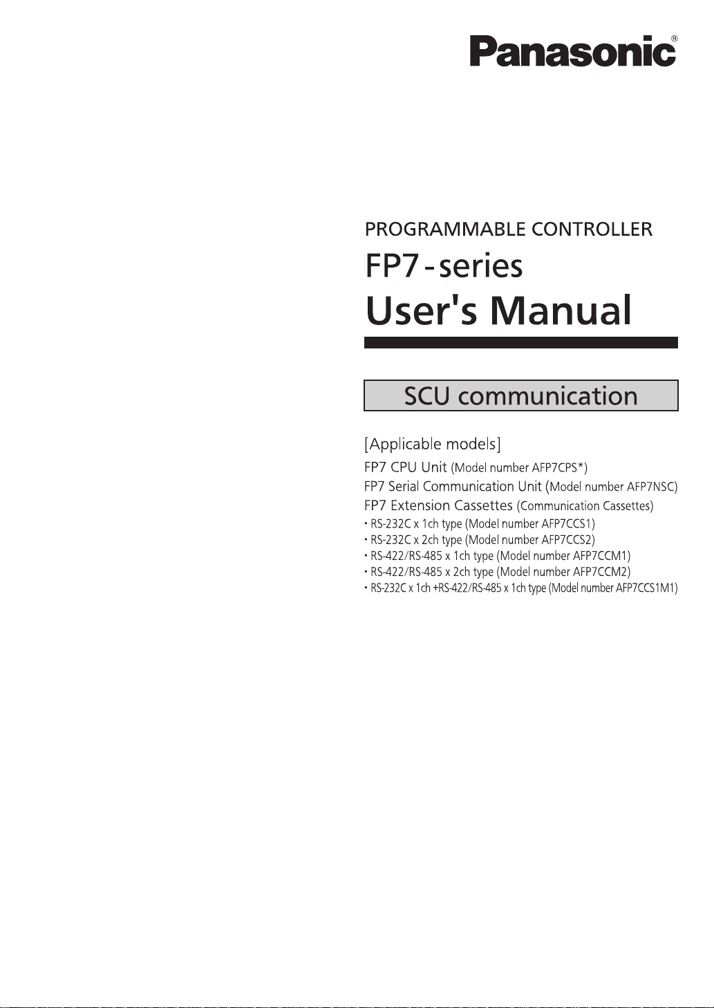
1.2.1 PLC Link Functions (MEWNET-W0)
Overview of function
A system can be configured for the PLC link (MEWNET-W0).
Exclusive internal relays “link relays (L)” and data registers “link registers (LD)” are shared
between the connected PLCs.
Among up to 16 PLCs, data can be exchanged with 1,008 link relay points and 128 link
register words.
Applications of PLC Link Functions (MEWNET-W0)
Among our FP series PLC, it can be used for link functions with the following models. It is also
capable of 1:1 communication via RS-232C port.
FP-X0 (L40MR / L60MR)
FP0R (RS485 type)
FPΣ (Using Communication cassette RS-485 type)
FP-X (Using Communication cassette RS-485 type)
FP2 Multi Communication Unit (Using Communication cassette RS-485 type)
1-4
1.2 Overview of Communication Functions
Phone: 800.894.0412 - Fax: 888.723.4773 - Web: www.clrwtr.com - Email: info@clrwtr.com
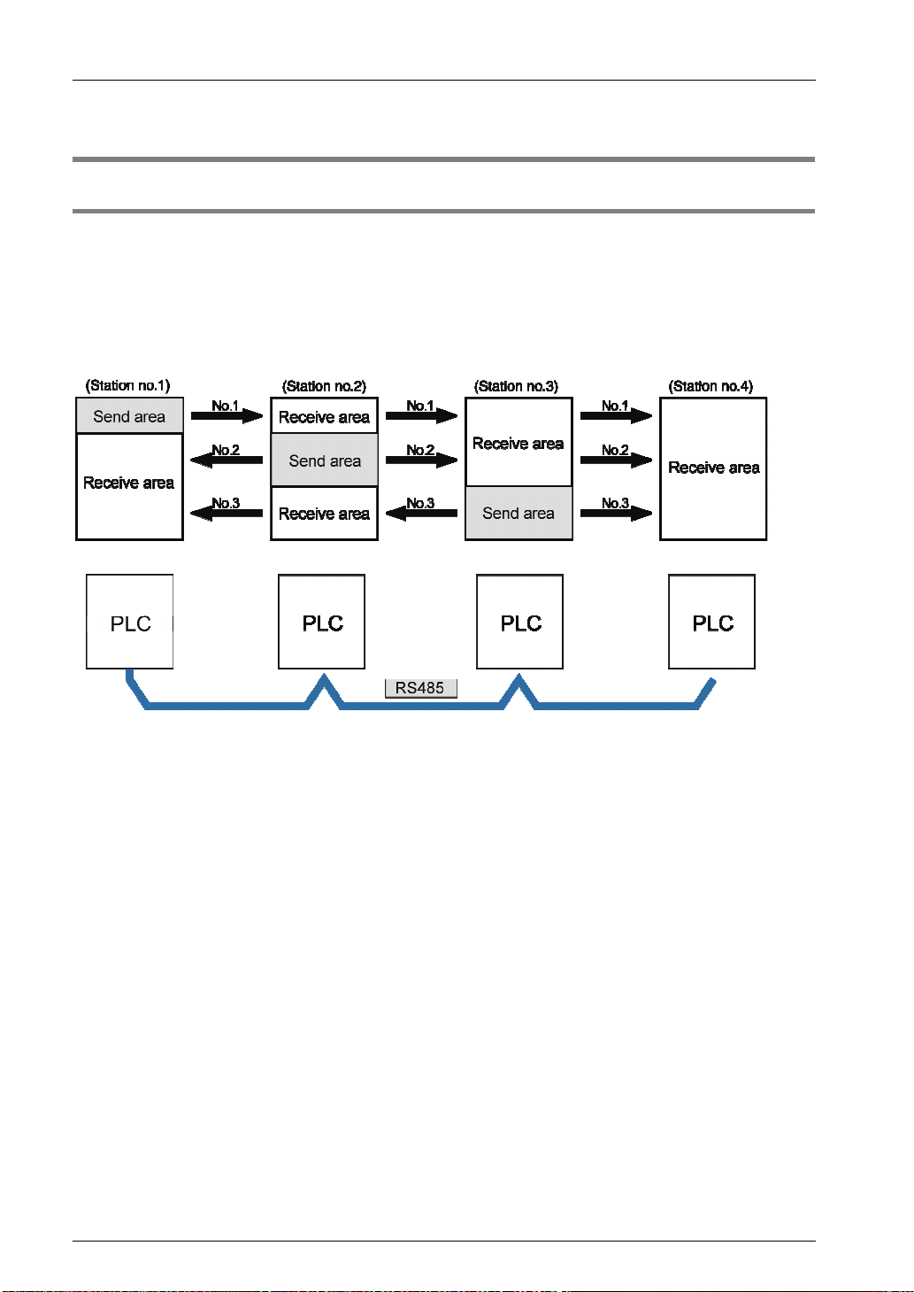
1.2.2 MEWTOCOL Master/Slave Communication
Overview of function
Execute communication using MEWTOCOL-COM, a communication protocol used by our PLC.
In master communication, PLC executes communication by sending commands to devices that
support MEWTOCOL, and receiving responses. Me ssages in accordance wit h the protocol are
automatically generated by PLC. In the user program, read ing and writin g can be done simply by
specifying the station no. an d memory a ddress an d executi ng SE ND/RECV instru ction s.
Slave communication is performed when the computer or display connected to PLC has th e
sending right, and sends commands, and PLC returns responses. In slave communication, PLC
responds automatically, so no program concerning com mu nic ation i s necessary on the P LC side.
The data size that can be sent or received in a single communication is up to 507 words for
register transmission (up to 1,014 words for MEWTOCOL7-COM) and 1 bit for bit transmission.
Master function
Slave function
Examples of applications of MEWTOCOL master communication
This is used for connection with a device that supports our PLC's protocol MEWTOCO L.
Programmable controller FP series
Displacement sensor HL series
Eco power meter KW series
Examples of applications of MEWTOCOL slave communication
This is used for connection with a device that supports our PLC's protocol MEWT OCOL-COM
master communication.
Programmable displays made by various manufacturers
1-5
Functions of Units and Restrictions on Combination
Phone: 800.894.0412 - Fax: 888.723.4773 - Web: www.clrwtr.com - Email: info@clrwtr.com
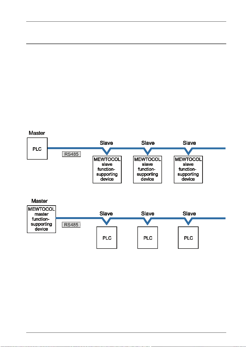
1.2.3 MODBUS RTU Master/Slave Communication
Overview of function
This is used for communicating with other devices that support the MODBUS RTU protocol.
In master communication, communication is performed when the master unit sends
instructions (command messages) to slave units and the slave unit returns responses
(response messages) according to t he instructions. Messages in accordance with the
protocol are automatically generated by PLC. In the user program, reading and writing can
be done simply by specifying the station no. and memory address and executing
SEND/RECV instructions.
Slave communication is performed when the higher device connected to PLC has the
sending right, and sends commands, and PLC returns responses. In slave communication,
PLC responds automatically, so no program concerning comm unication is necessary on the
PLC side.
The data size that can be sent or received in a single communication is up to 127 words for
register transmission and 2,040 bit for bit transmission.
Master function
Slave function
Examples of applications of MODBUS-RTU master communication
This is used for connection with a device that supports the MODBUS-RTU protocol.
Thermoregulator KT series
Devices from other manufacturers that support MODBUS-RTU
Examples of applications of MODBUS-RTU slave communication
This is used when access is made from the higher device using MODBUS-RTU commands.
1-6
1.2 Overview of Communication Functions
Phone: 800.894.0412 - Fax: 888.723.4773 - Web: www.clrwtr.com - Email: info@clrwtr.com
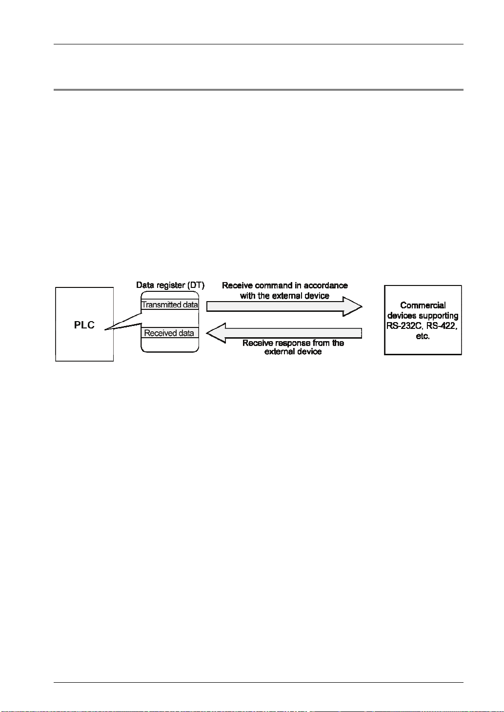
1.2.4 General-Purpose Communication
Overview of function
General-purpose communication is used when PLC executes communication in accordan ce
with the protocol of the partner device.
Formulation and sending of command messages to the partner device, and reception
processing of responses from the partner device, are performed by the user program.
Sending/receiving of data with an external device is executed via given operation memory
(e.g. data register).
Data are sent by converting commands in accordance with the partner device as strings into
ASCII text, setting them into a given data register, and executing GPSEND instruction.
Response received from the partner device is temporarily saved in the buffer. Based on the
reception done flag, GPRECV instruction is executed. The ASCII strings can be converted
into numerical data, etc. as necessary, by the user program.
The data size that can be sent or received in a single communication is up to 4,096 bytes.
(including control codes)
Applications of general-purpose communication
This is used for connection with devices made by differing manufacturers that have dedicated
communication protocols.
1-7

Functions of Units and Restrictions on Combination
Phone: 800.894.0412 - Fax: 888.723.4773 - Web: www.clrwtr.com - Email: info@clrwtr.com
1.3 Restrictions on Units C ombination
1.3.1 Restrictions on the Number of Installed Units
There are following restrictions depending on units to be used.
Unit type Number of installed units Remarks
Serial Communication Unit Max. 8 units
1.3.2 Restrictions on the Combination of Extension Cassettes
(Communication Cassettes)
One communication cassette can be attached to the CPU unit, and two communication
cassettes to the serial communication unit.
The FP7 communication cassette (Ethernet type) can be attached to the CPU only. It cannot
be attached to the serial communication unit (SCU).
1.3.3 Restrictions on Communication Functions to be Used
There are the following restrictions on functions to be used when using the SCU or ET-LAN
that is built in the CPU unit, or the serial communication unit (SCU).
Function to be used Restrictions
Up to two communication ports can be used. For using two ports, allocate
PLC link function
MEWTOCOL-COM master
MODBUS-RTU master
MEWTOCOL-COM slave
MEWTOCOL7-COM slave
MODBUS-RTU slave
General-purpose
communication
different link areas to them.
CPU with built-in SCU (COM.1 port)
Serial communication unit (COM.1 port)
A maximum of 16 communication ports and the number of connections in
combination can be used simultaneously.
CPU with built-in SCU (COM.1 port to COM. 2 port)
Serial communication unit (COM.1 port to COM.4 port)
CPU with built-in ET-LAN (User connections 1 to 16)
A maximum of 15 communication ports and the number of connections in
combination can be used simultaneously.
CPU with built-in SCU (COM.1 port to COM. 2 port)
Serial communication unit (COM.1 port to COM.4 port)
CPU with built-in ET-LAN
(System connections 1 to 4 / User connections 1 to 16)
There is no restriction.
1.3.4 Unit to be Used and Applicable Versions o f CPU Unit and FPWIN GR 7
For using the unit, the following versions of CPU unit and FPWINGR7 are required.
Unit type
FP7 Serial Communication Unit Ver.1.2 or later Ver.1.3 or later
Applicable versions
CPU unit FPWINGR7
Remarks
1-8
1.3 Restrictions on Units Combination
Phone: 800.894.0412 - Fax: 888.723.4773 - Web: www.clrwtr.com - Email: info@clrwtr.com
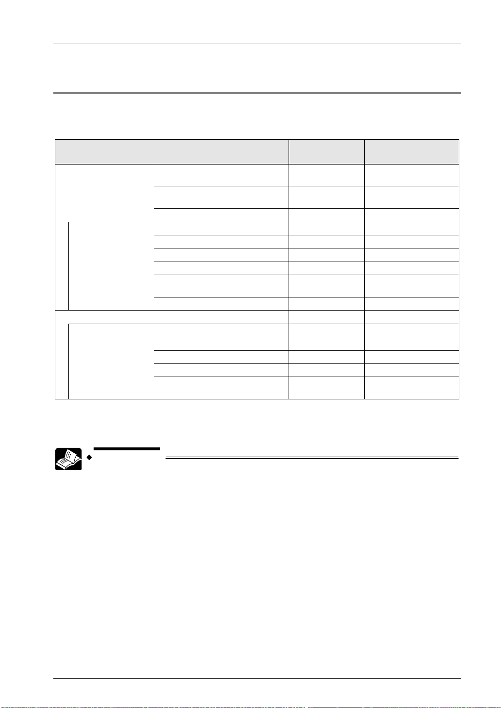
1.3.5 Restrictions on Consumption Current
Including other units, the consumption current should be within the allowable capacity of a
power supply unit.
Unit's consumption current table (24 V)
Product name Model number
196k steps, Built-in Ethernet
function
CPU Unit
When attaching
Extension Cassette
(Communication
Cassette) to CPU
Unit
(Note 1) (Note 2)
Serial Communication Unit AFP7NSC 50 mA or less
When attaching
Extension Cassette
(Communication
Cassette) to Serial
Communication Unit
(Note 1) (Note 2)
(Note 1) The consumption currents listed in the Extension Cassette column indicate the increased amount of the
CPU's consumption current which increases when each extension cassette is added.
(Note 2) The consumption current of extension cassette (communication cassette) varies according to the unit to
which the cassette is attached (CPU or serial communication unit).
120k steps, Built-in Ethernet
function
120k steps, No Ethernet function AFP7CPS3 200 mA or less
RS-232C x 1ch AFP7CCS1 35 mA or less
RS-232C x 2ch AFP7CCS2 60 mA or less
RS-422 / 485 x 1ch AFP7CCM1 60 mA or less
RS-422 / 485 x 2h AFP7CCM2 90 mA or less
RS-232C x 1ch
RS-422 / 485 x 1ch
Ethernet AFP7CCET 35 mA or less
RS-232C x 1ch AFP7CCS1 20 mA or less
RS-232C x 2ch AFP7CCS2 40 mA or less
RS-422 / 485 x 1ch AFP7CCM1 30 mA or less
RS-422 / 485 x 2h AFP7CCM2 60 mA or less
RS-232C x 1ch
RS-422 / 485 x 1ch
AFP7CPS4E 200 mA or less
AFP7CPS3E 200 mA or less
AFP7CCS1M1 70 mA or less
AFP7CCS1M1 50 mA or less
Consumption
current (mA)
REFERENCE
For information on the restrictions on the combination of units, also refer to FP7 CPU
Unit User's Manual (Hardware).
1-9

Functions of Units and Restrictions on Combination
Phone: 800.894.0412 - Fax: 888.723.4773 - Web: www.clrwtr.com - Email: info@clrwtr.com
1-10

Phone: 800.894.0412 - Fax: 888.723.4773 - Web: www.clrwtr.com - Email: info@clrwtr.com
2
Names and Functions of
Parts
Names and Functions of Parts
Phone: 800.894.0412 - Fax: 888.723.4773 - Web: www.clrwtr.com - Email: info@clrwtr.com
2.1 Names and Functions of Parts
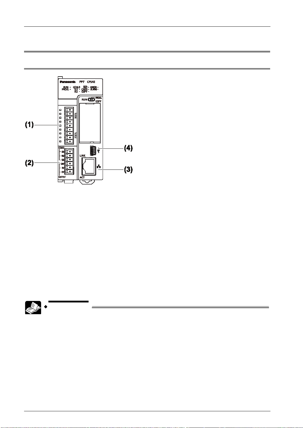
2.1.1 Communication Port of CPU Unit
(In the above figure, a communication cassette is attached to the COM.1 and COM.2 ports.)
Names and Functions of Parts
(1) COM.1 and COM.2 ports
Attach a separately sold communication cassette to use these ports. A blank cover is fitted
when the unit is shipped.
(2) COM.0 port, GT power supply terminals
This is an RS-232C port that is equipped to a standard model of CPU unit. It is equipped with
power supply terminals (5 VDC and 24 VDC) to which a GT series programmable display can
be connected.
(3) LAN port
This is equipped to a standard model of CPU unit. This is used for connection to Ethernet.
(4) USB port
This is equipped to a standard model of CPU unit. This is used for connecting tool software.
REFERENCE
For details of the communication method using LAN port, refer to FP7 CPU
Unit User's Manual (LAN port communication).
For details of the communication using Communication cassette (Ethernet
type) AFP7CCET, refer to FP7 series User's Manual (Communication
cassette Ethernet type).
2-2
2.1 Names and Functions of Parts
Phone: 800.894.0412 - Fax: 888.723.4773 - Web: www.clrwtr.com - Email: info@clrwtr.com
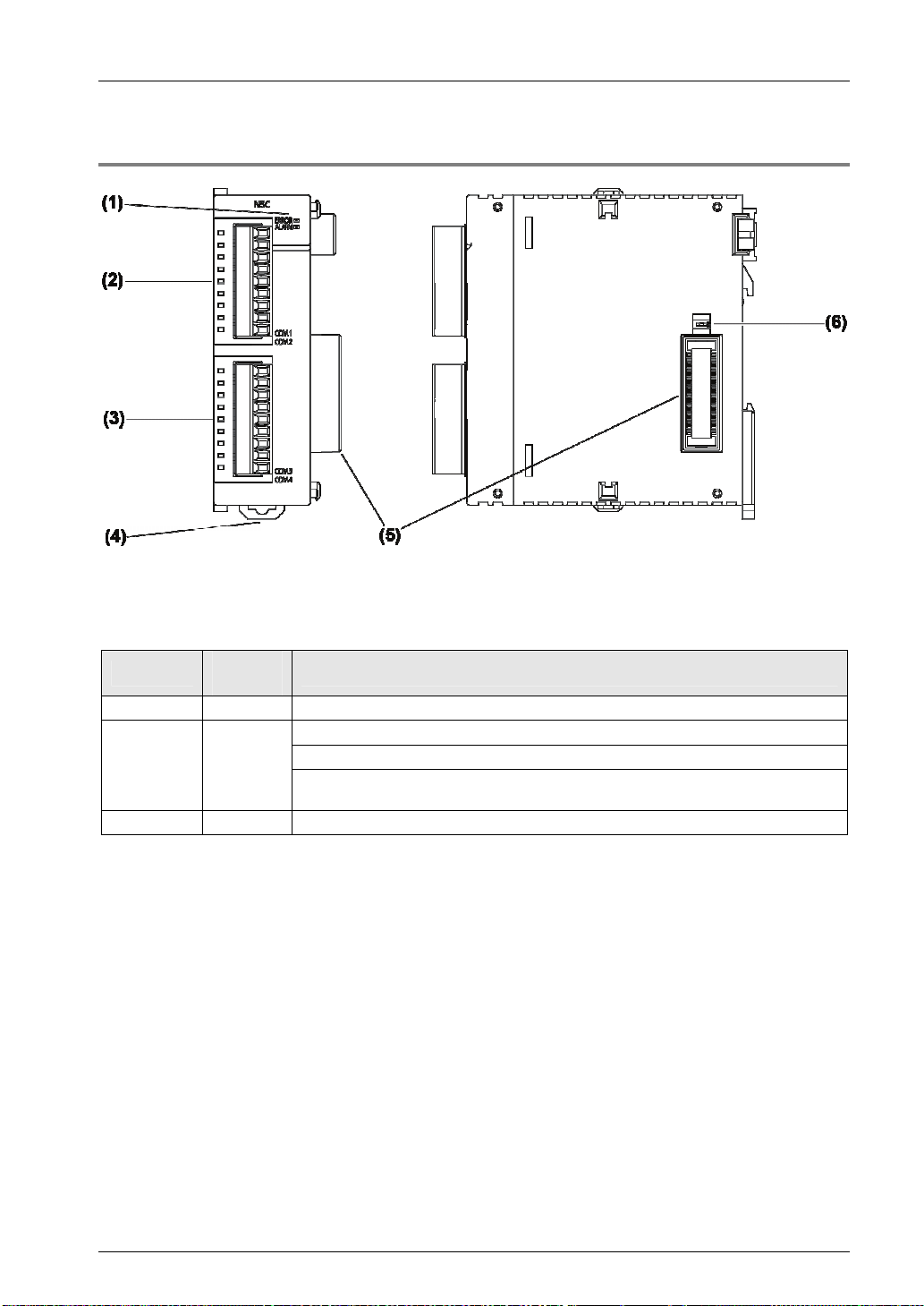
2.1.2 Parts Names and Functions of Serial Communication Unit
(In the above figure, two communication cassettes are attached.)
Names and Functions of Parts
(1) Operation monitor LEDs
Display
- Blue Lights when the power supply of the CPU unit is on.
ERROR Red
ALARM Red Lights when an error occurs in hardware.
LED
color
Description
Lights when the configuration setting is incorrect, or a communication error occurs.
Flashes when the factory acceptance test switch is on. (Flashing cycle: 100 ms)
Flashes when an extension cassette that cannot be used is installed. (Flashing
cycle: 500 ms)
(2) COM.1 and COM.2 ports
Attach a separately sold communication cassette to use these ports. No blank cover is fitted
when the unit is shipped.
(3) COM.3 and COM.4 ports
Attach a separately sold communication cassette to use these ports. A blank cover is fitted
when the unit is shipped.
(4) DIN hook
This is used to fix the unit to a DIN rail.
(5) Unit connector
This is used to connect the internal circuit of an I/O unit or advanced unit.
(6) Factory acceptance test switch
This is used for factory acceptance test. Do not turn it on.
2-3

Names and Functions of Parts
Phone: 800.894.0412 - Fax: 888.723.4773 - Web: www.clrwtr.com - Email: info@clrwtr.com
2-4

Phone: 800.894.0412 - Fax: 888.723.4773 - Web: www.clrwtr.com - Email: info@clrwtr.com
3
Wiring the COM. Port
Wiring the COM. Port
Phone: 800.894.0412 - Fax: 888.723.4773 - Web: www.clrwtr.com - Email: info@clrwtr.com
3.1 Attaching a Communication Cassette
3.1.1 Attachment Instructions
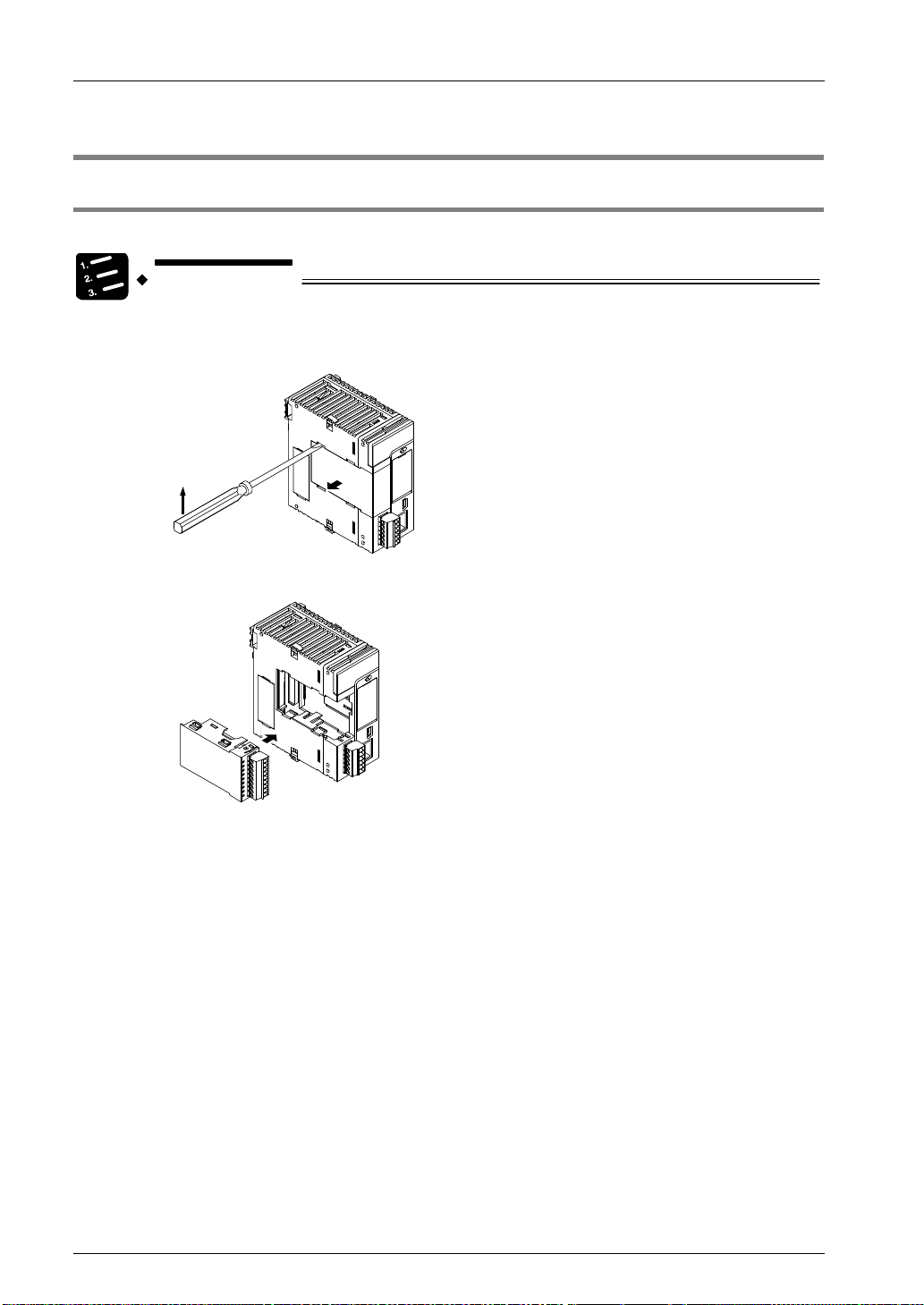
When an optional Communication Cassette is to be used, attach it in the following procedures.
PROCEDURE
1. Using a flathead screwdriver, remove the cover on the side of the CPU unit.
You will find four toggles.
2. Attach a desired Communication Cassette.
The illustration is the CPU unit. As for the Serial Communication Unit, the
attachment procedure is the same.
3-2
3.2 Wiring of COM Port Terminal Block
Phone: 800.894.0412 - Fax: 888.723.4773 - Web: www.clrwtr.com - Email: info@clrwtr.com
3.2 Wiring of COM Port Terminal Blo ck
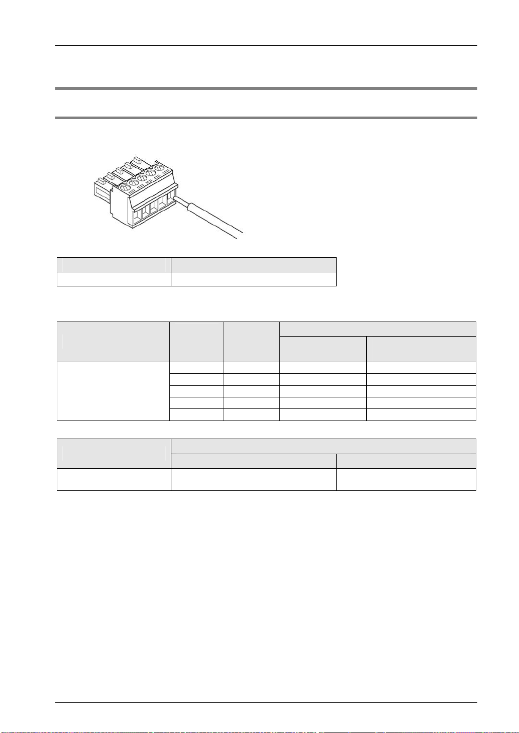
3.2.1 Suitable Wires and Tools
A screw-down connection type for terminal block is used for the communication port. Use the
following items for wiring.
Suitable wires (strand wire)
Size Nominal cross-sectional area
AWG #28 to 16 0.08 mm2 to 1.25 mm2
Pole terminal with a compatible insulation sleeve
If a pole terminal is being used, the following models should be used.
Part no.
With insulating
sleeve
Without insulating
sleeve
Manufacturer
Phoenix Contact
Crosssectional
area
0.25 mm2 AWG #24 AI 0.25-6 BU A 0.25-7
0.34 mm2 AWG #22 AI 0.34-6 TQ A 0.34-7
0.50 mm2 AWG #20 AI 0.5-6 WH A 0.5-6
0.75 mm2 AWG #18 AI 0.75-6 GY A 0.75-6
1.00 mm
Size
2
AWG #18 - A 1-6
Pressure welding tool for pole terminals
Manufacturer
Phoenix Contact
Model no.
Part no. Product no.
CRIMPFOX 6 1212034
Screwdriver for terminal block
To tighten the terminals, use a screwdriver by Phoenix Contact (model No. SZS 0.4 x 2.5,
product No. 1205037, blade size 0.4 x 2.5) or our screwdriver (part No. AFP0806). The
tightening torque should be 0.22 to 0.25 N·m.
3-3
Wiring the COM. Port
-
Phone: 800.894.0412 - Fax: 888.723.4773 - Web: www.clrwtr.com - Email: info@clrwtr.com
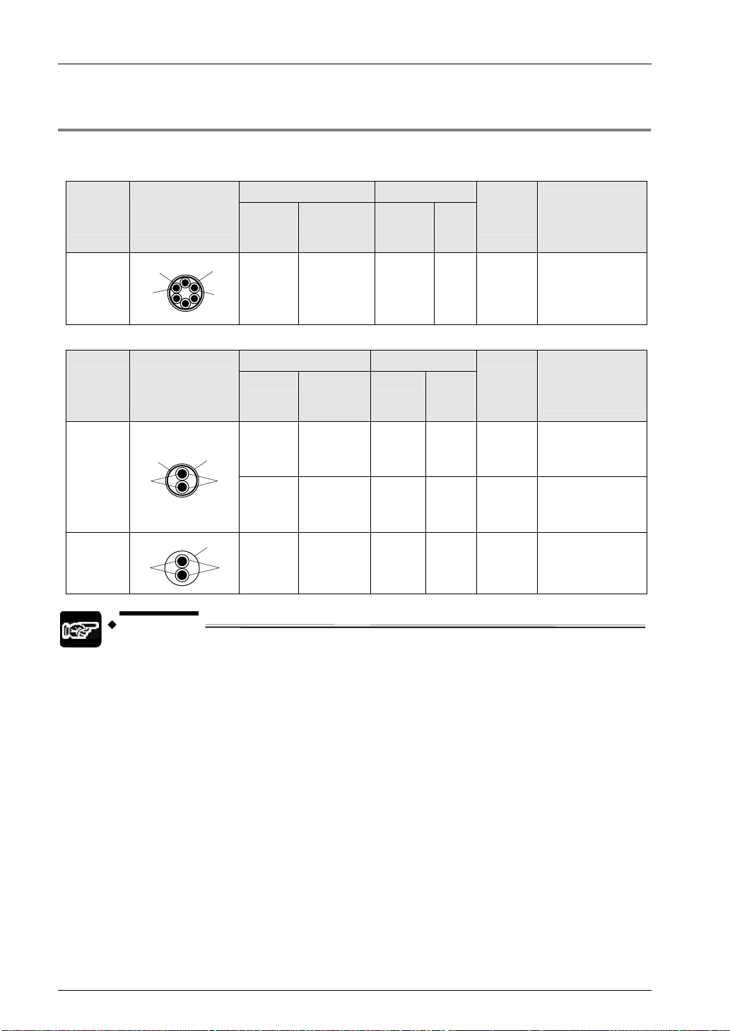
3.2.2 Applicable Cable
Use a cable as prescribed below.
Suitable wires (strand wire): For RS-232C / RS-422 communication
Conductor Insulator
Classifi-
cation
Cross-sectional
view
Size
Resistance
value
(at 20°C)
Material
Thick-
ness
Cable
diam.
Sample
appropriate
cable
Shielded
multi-core
cable
Shield
Conductor
Cover
Insulator
0.3 mm2
(AWG22)
or larger
Max.
58.8 Ω/km
Vinyl
chloride
Max.
0.3 mm
Suitable wires (strand wire): For RS-485 communication
Conductor Insulator
Classifi0c
ation
Cross-sectional
view
Size
Resistance
value
Material
Thick-
ness
(at 20°C)
2
Max.
16.8 Ω/km
Max.
33.4 Ω/km
2
Max.
25.1 Ω/km
Polyethylene
Polyethylene
Polychlorinated
biphenyl
Max.
0.5 mm
Max.
0.5 mm
Max.
0.6 mm
Shielded
twisted
pair
VCTF
Shield
Conductor
Conductor
NOTES
1.25 mm
(AWG16)
Cover
or larger
Insulator
0.5 mm2
(AWG20)
or larger
Cover
0.75 mm
(AWG18)
Insu
lator
or larger
Use shielded twisted pair cables.
Use only one type of transmission cable. Do not mix more than 1 type.
Twisted pair cables are recommended in noisy environments.
When using shielded cable with crossover wiring for the RS-485
transmission line, grounded one end.
Approx.
6.6 mm
Cable
diam.
Approx.
8.5 mm
Approx.
7.8 mm
Approx.
6.6 mm
Onamba Co. Ltd.
ONB-D6 × 0.3 mm
2
Sample
appropriate
cable
Hitachi Cable, Ltd.
KPEV-S1.25 mm
1P
Belden Inc., 9860
Hitachi Cable, Ltd.
KPEV-S0.5 mm
1P
Belden Inc., 9207
VCTF0.75 mm2 × 2C
(JIS)
2
×
2
×
3-4
3.2 Wiring of COM Port Terminal Block
Phone: 800.894.0412 - Fax: 888.723.4773 - Web: www.clrwtr.com - Email: info@clrwtr.com
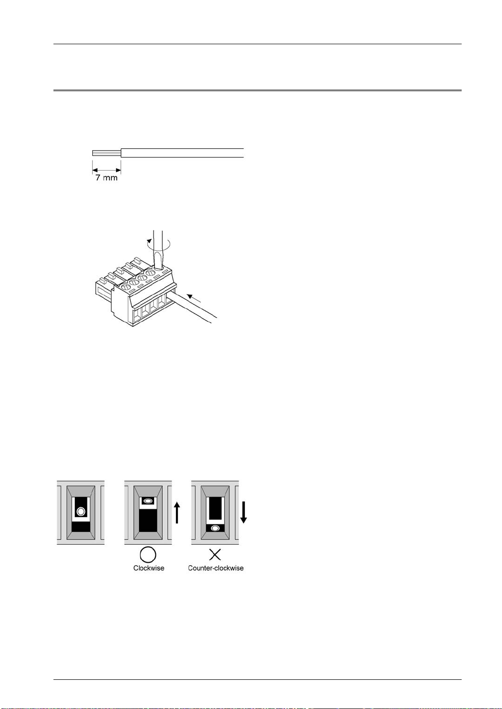
3.2.3 Wiring Method
Wiring method
(1) Remove a portion of the wire’s insulation.
(2) Insert wire into terminal hole until it stops. Tighten screw clockwise to fix wire in place.
(The tightening torque: 0.22 to 0.25 N·m (2.3 to 2.5 kgf·cm))
Precautions on wiring
The following precautions should be observed, to avoid broken or disconnected wire s.
When removing the wire’s insulation, be careful not to scratch the core wire.
Do not twist the wires to connect them.
Do not solder the wires to connect them. The solder may break due to vibration.
After wiring, make sure stress is not applied to the wire.
In the terminal block socket construction, if the wire is fastened upon counter-clockwise
rotation of the screw, the connection is faulty. Disconnect the wire, check the terminal hole,
and then re-connect the wire.
3-5
Wiring the COM. Port
Phone: 800.894.0412 - Fax: 888.723.4773 - Web: www.clrwtr.com - Email: info@clrwtr.com
3.3 Wiring for CPU Unit (GT Power Supply and COM0 Port)
3.3.1 Handling of GT Power Supply Terminals
GT power supply terminals can be used as power supply terminals for the GT series of our
programmable displays.
In accordance with the model to be used, use either 5V DC or 24V DC.
NOTES
GT power supply terminals (5V DC / 24V DC) are design exclusively for the
GT series of our programmable displays. Do not use the terminals for other
devices.
GT power supply terminals and COM0 port (RS-232C) are insulated inside.
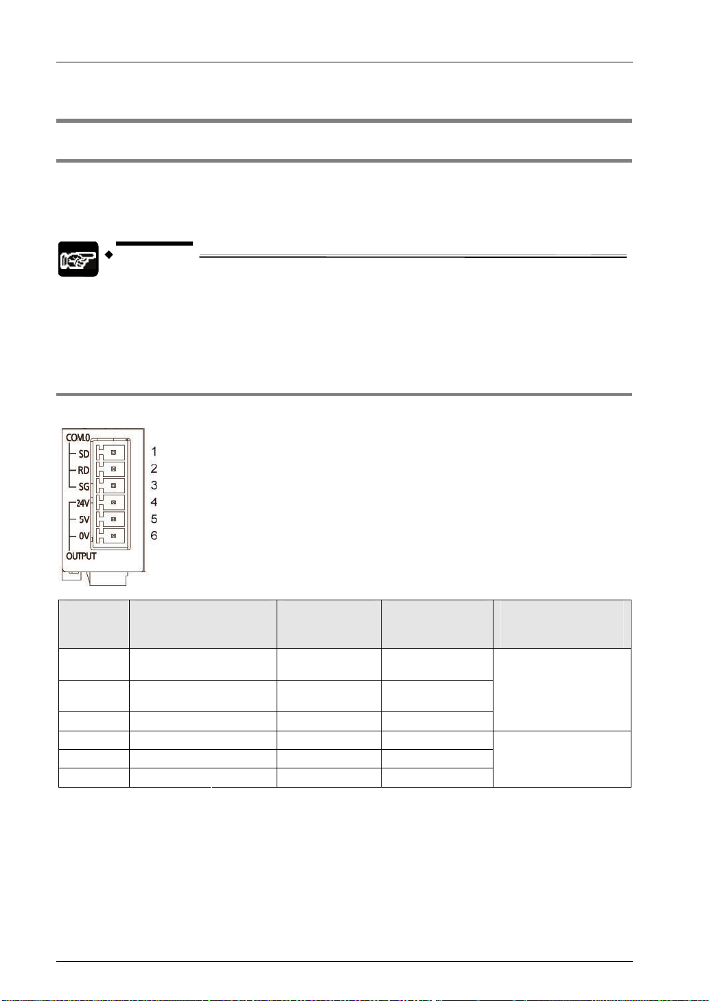
3.3.2 Terminal Layouts and Examples of Wiring
Layout for GT power supply terminals and COM0 port terminals
Terminal
no.
1 COM.0 SD Sent data
2 RD Received data
3 SG Signal Ground -
4 OUTPUT 24V 24V 5 5V 5V 6 0V 0V -
Terminal part
Symbol
Functions
that can be
allocated
Signal direction
PLC →
External device
PLC ←
External device
Ports that can be
allocated
in the software
COM.0
-
3-6
 Loading...