

Page 1

Programmable Controller
FP0H Control Unit
User's Manual
EtherNet/IP Edition
[Applicable model]
AFP0HC32ET/AFP0HC32EP
WUME-FP0HEIP-05
2021.2 panasonic.net/id/pidsx/global
Page 2

(MEMO)
2 WUME-FP0HEIP-05
Page 3

Introduction
Thank you for purchasing a Panasonic product. Before you use the product, please carefully
read through the user’s manual, and understand it in detail to use the product properly.
Types of Manual
● This manual describes the "EtherNet/IP communication function" implemented in FP0H
Control Unit.
● There are different types of user’s manual for the FP0H series. Please refer to a relevant
manual for the unit and purpose of your use.
● The manuals can be downloaded on our download center: https://
industrial.panasonic.com/ac/e/dl_center/.
Unit name or purpose of
use
FP0H Control Unit
Positioning Function/PWM
Output/High-speed
Counter Function
Serial Communication
Function
Ethernet Communication
Function
EtherNet/IP
Communication Function
Logging trace function FP0H User‘s Manual (Logging/Trace Function) WUME-FP0HLOG
FP0H Extension
(Communication) Cassette
FP0H Positioning Unit FPsigma Positioning Unit User’s Manual ARCT1F365E
FP0H Positioning Unit RTEX
Manual name Manual code
FP0H User‘s Manual (Basic) WUME-FP0HBAS
FP0H Programming Manual WUME-FP0HPGR
FP0H Programming Manual (SD Card Access
Instructions)
FP0H User‘s Manual
(Positioning/PWM Output/High-speed Counter)
FP0H User‘s Manual (COM Communication) WUME-FP0HCOM
FP0H User‘s Manual (Ethernet Communication) WUME-FP0HET
FP0H User‘s Manual (EtherNet/IP) WUME-FP0HEIP
FP0H User‘s Manual (COM Communication) WUME-FP0HCOM
FP0H Positioning Unit RTEX User’s Manual
(FPWIN GR7)
WUME-FP0HSD
WUME-FP0HPOS
WUME-FP0HRTEXGR7
WUME-FP0HEIP-05 iii
Page 4
SAFETY PRECAUTIONS
● To prevent accidents or personal injuries, please be sure to comply with the following items.
● Prior to installation, operation, maintenance and check, please read this manual carefully for proper use.
● Before using, please fully understand the knowledge related to the equipment, safety precautions and all
other precautions.
● Safety precautions are divided into two levels in this manual: Warning and Caution.
Incorrect operation may lead to death or serious injury.
● Take appropriate safety measures to the external circuit of the product to ensure the security of the whole
system in case of abnormalities caused by product failure or external.
● Do not use this product in areas with inflammable gases.
Otherwise it may lead to an explosion.
● Do not put this product into a fire.
Otherwise it could cause damage to the battery or other electronic parts.
Incorrect operation may lead to injury or material loss.
● To prevent the excessive exothermic heat or smoke generation of the product, a certain margin is required
for guaranteed characteristics and performance ratings of relative products.
● Do not decompose or transform it.
Otherwise it will lead to the excessive exothermic heat or smoke generation of the product.
● Do not touch terminal blocks during power-on.
Otherwise it may result in an electric shock.
● Set an emergency stop and interlock circuit in the external devices.
● Connect wires and connectors reliably.
Otherwise it may lead to the excessive exothermic heat or smoke generation of the product.
● Do not undertake construction (such as connection and disconnection) while the power supply is on.
It could lead to an electric shock.
● If the equipment is used in a manner not specified by the Panasonic, the protection provided by the
equipment may be impaired.
● This product has been developed/produced for industrial use only.
Description on Copyright and Trademarks
● The copyright of this manual is owned by Panasonic Industrial Devices SUNX Co., Ltd
● Unauthorized reproduction of this manual is strictly prohibited.
● Windows is a registered trademark of Microsoft Corporation in the U.S. and other countries.
● Ethernet is a registered trademark of Fuji Xerox Co., Ltd. and Xerox Corporation.
● EtherNet/IP is a registered trademark of ODVA (Open DeviceNet Vendor Association).
● SDHC and SD logos are trademarks of LLC.
● Other company and product names are trademarks or registered trademarks of their respective companies.
Network Security
When this product is connected to a network, you might receive damage as listed below.
(1) Information leakage or outflow through this product
(2) Fraudulent operation of this product by a malicious third party
(3) Obstructing or stopping this product by a malicious third party
Sufficient network security measures, including the following measures, should be taken at your
own risk to prevent such damages.
● Use this product on a network where safety is secured by using a firewall.
iv
WUME-FP0HEIP-05
Page 5

● When using this product on a system where a PC is connected, make sure that checking and
cleaning of infection by computer virus or malicious program is performed periodically.
● In order to prevent malicious attacks, set user name and password to limit users who can log
in.
● Take measures such as limiting an access through a user authentication method so as not to
leak information to the network such as image data, authentication information (user name
and password), alarm email information, FTP server information, DDNS server information,
etc.
● Be sure to close all browsers immediately after accessing this product as an administrator.
● Periodically change the administrator's password.
● Do not install this product in a location where the product or cables can be easily damaged.
● Furthermore, it is recommended that the product be used in an environment that has VPN
(Virtual Private Network) or leased line network.
Glossary
The following terms are used in this manual and the EtherNet/IP setting tool.
Term Description
Originator
Target he side which the connection is opened is called target, such as PLC, I/O devices.
Scan List
I/O map
EDS file
(Electric data sheet)
Node no.
Connection setting The details of the connections with targets registered in the scan list are set.
Node name Arbitrary node names can be given.
Device name Device names of targets. The device name is registered in the EDS file.
Connection Name
Application Type
The side which opens the connection of the cyclic communication is called
originator, i.e. controllers such as PLC.
Connection setting with targets registered in FP0H. Information required for the
communication with the targets and the device allocation of own unit are registered.
For FP0H, the connection with targets are established according to the scan list.
Information required for the transmission from the own unit (FP0H) to other PLCs
and the device allocation of the own unit are registered.
EDS files are provided for each product by each vendor. This file contains the
information on the communication for registering targets in the scan list.
The EDS files of each target should be registered for constructing the scan list with
the setting tool.
A node number is set when a target is registered in the scan list.
Numbers that do not overlap are allocated in the scan list as node numbers.
Node numbers are not used in the cyclic communication, however, as each target
is recognized by these numbers, they are used for monitoring the communication
state of each node or controlling the start/stop of the communication.
The type of the connection manager registered in the EDS file is selected by the
name. By selecting this, the application type (communication method) is changed.
The communication method can be selected by the application type.
Three communication methods are available;
1: Exclusive Owner (Two-way communication)
2: Input Only
3: Listen Only
Although "Exclusive Owner" and "Input Only" are independent connections, "Listen
Only" can be connected only when either of the above connections is established,
and it will be automatically cut if the independent connection is disconnected.
Also, it will be reconnected automatically when the above independent connection
is reconnected.
When FP0H is used as a target, "Input Only" can be selected.
WUME-FP0HEIP-05 v
Page 6

Term Description
Set the operation method of "Compatibility Check" , which checks the information of
the connected target device against the revision of the EDS file.
Three verification methods are available. The default is "Follow Adapter(Target)
Compatibility Check
Communication Method
(Tag/Instance)
Input Send Trigger
COS Transmission
Disable Time
Timeout Period
Input Information (T>O) This is the setting for the transmission from a target to the FP0H (originator).
Output Information (O>T) This is the setting for the transmission from the FP0H (originator) to a target.
RPI
(Requested Packet
Interval)
Point to Point
(1:1 communication)
Multicast
(Multicast communication)
TTL
Instance ID/Tag name
Data Size
Rule".
1: Check
2: Not check
3: Follow Adapter(Target) Rule
For connecting from an originator to target, there are two methods to specify the
device area of the target.
by specifying numbers (Instance)
by specifying symbols (Tag).
When setting connections, the methods available for each target are displayed.
For using the FP0H as a target, either method can be selected.
However, the selectable instance numbers for the instance method are 100 to 199.
The transmission timing is selected from Cyclic or COS (Change of state).
However, COS depends on devices.
COS is basically a cyclic communication, however, it also performs transmission
when sent data changes.
The FP0H does not support COS.
Transmission disable time (RPI of input information x 1/4) is displayed when "Input
Send Trigger" is set to "Change of State (COS)".
Even if the unit detects the change in data, it is not sent within the transmission
disable time.
In the cyclic communication, transmission data is sent as UDP packet. The timeout
is judged on a receiver side.
The timeout period is selected from 4, 8, 16, 32, 64, 128, 256 and 512 times of RPI.
The timeout period should be 10 msec or more.
RPI can be specified for T>O direction and O>T direction separately, so each
timeout period may be different values.
Set the transmission interval for the cyclic communication. Set a value within the
communication capacity of a target. The usable RPI range depends on devices.
For the FP0H, it is 1 ms to 10 s (by 0.5 ms).
One to one communication is performed between an originator and a target.
Transmitted packets are received only by each other.
Other devices connected to the same HUB do not receive those transmission
packets.
Transmission data is sent as a multicast packet. By connecting multiple originators
to one target, one multicast packet can be received by multiple originators.
(Note) Multicast packets are basically received by all devices connected to the
same HUB which includes the devices unrelated to the communication, and it leads
to an unnecessary communication load.
When using the multicast communication, set not to exceed 100% by the load
factor calculation of the setting tool.
TTL (Time To Live) is used to set the hierarchies of the network in which
transmission packets can exist when sending multicast packets to other PLCs.
Set an instance ID or tag name according to the communication method of the
selected connection.
The data sizes of the originator and target for the cyclic communication must be the
same. When they do not match, the communication cannot be performed.
vi WUME-FP0HEIP-05
Page 7

Term Description
Parameter setting
PPS performance index
(Packet per sec)
Normal packet and
large packet
Protocol used for
cyclic communication
Heartbeat
Forward open
Large forward
open
RUN/IDLE bit
Data size, instance ID and other parameters that can be changed in the EDS file
can be changed.
This is an index of sent/received packets processed in one second.
The packet whose size is within 510 bytes is called normal packet. The packet
whose size is 511 bytes to 1444 bytes is called large packet.
The maximum communication performance varies according to the data size used
for communication.
Performance index of FP0H
For 510 bytes or less: Max. 5000 pps
For 511 bytes or more: Max. 2500 pps
The cyclic communication is performed using UDP. The used port number is 2222.
For "Input Only" or "Listen Only", a packet called heartbeat whose data size is zero
is sent from the originator (FP0H). For the RPI of the heartbeat, the value 16 times
of the RPI of transmitted data from a target is automatically applied.
The heartbeat is used for confirming the continuation of the connection on the
target side. It is used for detect the timeout.
This is a command for opening the connection of EtherNet/IP and sent using TCP.
The used port number is 44818.
This is a command for opening the connection when sending/receiving data whose
size is larger than 511 bytes.
Operation state flag (RUN/IDLE) sent by connected devices in cyclic
communication.
RUN : 1
IDLE : 0
When the RUN/IDLE bit of the originator does not change to RUN, the target may
not operate properly. For details, refer to "5.2.3 RUN/IDLE Bit".
● Do not use "2222" and "44818" for the port numbers set to the connections of Ethernet
communication.
WUME-FP0HEIP-05
vii
Page 8

(MEMO)
viii WUME-FP0HEIP-05
Page 9

Table of Contents
1 FP0H EtherNet/IP Function ..................................................................1-1
1.1 What is EtherNet/IP? ..........................................................................1-2
1.1.1 Overview of EtherNet/IP .................................................................. 1-2
1.1.2 FP0H EtherNet/IP Function ............................................................. 1-2
1.2 Names and Functions of Parts............................................................1-4
1.2.1 Control Unit ...................................................................................... 1-4
1.2.2 LED Displays When PLC Operates ................................................. 1-4
1.3 Restrictions .........................................................................................1-6
2 Cyclic Communication .........................................................................2-1
2.1 Cyclic Communication Function..........................................................2-2
2.1.1 Overview of Cyclic Communication ................................................. 2-2
2.1.2 Operation of Cyclic Communication................................................. 2-3
2.1.3 Data Refresh of Cyclic Communication ........................................... 2-3
2.1.4 Data Area Specifications Using Tag/Instance .................................. 2-4
2.2 Cyclic Communication of FP0H ..........................................................2-6
2.2.1 Connection using FP0H as originator .............................................. 2-6
2.2.2 Connection Using FP0H as Target................................................... 2-7
2.2.3 Example of Configuration When FP0H is Originator and Target...... 2-7
3 Setting Procedure .................................................................................3-1
3.1 Overview of Settings...........................................................................3-2
3.1.1 System Example .............................................................................. 3-2
3.1.2 Setting Procedure ............................................................................ 3-2
3.2 Initial Setting of Ethernet /IP ...............................................................3-4
3.2.1 Ethernet Settings ............................................................................. 3-4
3.2.2 Starting EtherNet/IP Setting Screen ................................................ 3-5
3.2.3 EtherNet/IP Basic Configuration ...................................................... 3-5
3.2.4 Items of Ethernet /IP Basic Configuration ........................................ 3-6
3.3 Settings of Connection Using FP0H as Originator..............................3-8
3.3.1 Settings ............................................................................................ 3-8
3.3.2 Registering EDS File of Target Device............................................. 3-8
3.3.3 Adding Target in Scan List ............................................................... 3-9
3.3.4 Setting IP Address of Target ............................................................ 3-10
3.3.5 Setting Tag/Instance ........................................................................ 3-11
3.3.6 Specifying Data Area Corresponding to Tag/Instance ..................... 3-13
3.3.7 Reference: Setting of Target "FP0H(B)"........................................... 3-15
3.4 Settings of Connection Using FP0H as Target ...................................3-16
3.4.1 Settings ............................................................................................ 3-16
3.4.2 Adding I/O Map to Scan List ............................................................ 3-16
3.4.3 Registering Tag Name/Instance ID .................................................. 3-17
3.4.4 Registering Data Area Corresponding to Tag/Instance.................... 3-18
3.4.5 Reference: Setting of Originator "FP7" ............................................ 3-19
3.5 Confirmation of Load Factor Calculation.............................................3-21
3.5.1 Load Factor Calculation ................................................................... 3-21
WUME-FP0HEIP-05
ix
Page 10

3.5.2 Displaying Load Factor Calculation ................................................. 3-21
3.6 Saving EtherNet/IP Settings ...............................................................3-22
3.6.1 Saving EtherNet/IP Settings in Project ............................................ 3-22
3.6.2 Saving/Reading EtherNet/IP Settings in File ................................... 3-22
3.6.3 Writing EtherNet/IP Settings to FP0H .............................................. 3-23
4 Tool Operation.......................................................................................4-1
4.1 Scan List Window ...............................................................................4-2
4.1.1 Display Contents of Scan List Window ............................................ 4-2
4.1.2 Operations in Scan List Window ...................................................... 4-3
4.2 Device List Window.............................................................................4-7
4.2.1 Display Contents of Device List Window ......................................... 4-7
4.2.2 Operations from EDS File Menu...................................................... 4-7
4.3 Various Setting Screens......................................................................4-9
4.3.1 Operations in Device Setting Screen ............................................... 4-9
4.3.2 Operations in Connection Setting Screen........................................ 4-9
4.3.3 Operations in I/O Map Setting Screen ............................................. 4-12
4.3.4 Display Contents of Calculate Load Factor Screen ......................... 4-13
4.3.5 Display Contents of Device Property Screen................................... 4-15
4.3.6 Switching Tabs in Each Setting Screen ........................................... 4-16
5 Startup and Operation ..........................................................................5-1
5.1 Startup Operation of Cyclic Communication.......................................5-2
5.1.1 When FP0H is Originator ................................................................. 5-2
5.1.2 When FP0H is Target....................................................................... 5-3
5.2 Checking EtherNet/IP Communication State......................................5-4
5.2.1 Unit Annunciation Relays................................................................. 5-4
5.2.2 Cyclic Communication State Tables of EtherNet/IP ......................... 5-4
5.2.3 RUN/IDLE Bit ................................................................................... 5-4
5.3 Judgement and Operation of Abnormality ..........................................5-6
5.4 Delay Time of Communication Data ...................................................5-7
5.4.1 Delay time of sent data .................................................................... 5-7
5.4.2 Delay Time of Reception Data ......................................................... 5-7
6 Instruction References .........................................................................6-1
6.1 High-level Instructions Used for EtherNet/IP Control..........................6-2
6.1.1 Information Acquisition of EtherNet/IP (F465 ETSTAT) ................... 6-2
7 Reference Information..........................................................................7-1
7.1 Calculation Method of Load Factor.....................................................7-2
7.2 Cyclic Communication: List of Abnormal Statuses .............................7-5
7.3 PLC Link and Ethernet Switch ............................................................7-8
8 Appendix................................................................................................8-1
8.1 Supported Data Types........................................................................8-2
x
WUME-FP0HEIP-05
Page 11

1 FP0H EtherNet/IP Function
1.1 What is EtherNet/IP? ..........................................................................1-2
1.1.1 Overview of EtherNet/IP .................................................................. 1-2
1.1.2 FP0H EtherNet/IP Function ............................................................. 1-2
1.2 Names and Functions of Parts............................................................1-4
1.2.1 Control Unit ...................................................................................... 1-4
1.2.2 LED Displays When PLC Operates ................................................. 1-4
1.3 Restrictions .........................................................................................1-6
WUME-FP0HEIP-05 1-1
Page 12
FP0H
Connection 1
Connection 2
: Opens connection. : Sends cyclic data.
PLC
Originator
Target Originator
Target
1.1 What is EtherNet/IP?
1.1 What is EtherNet/IP?
1.1.1 Overview of EtherNet/IP
EtherNet/IP (Ethernet Industrial Protocol) is an industrial multi-vendor realtime Ethernet system
for executing the communication protocol for CIP (Common Industrial Protocol) control in an
application layer on standard Ethernet.
Cyclic communication can be performed among devices compatible with EtherNet/IP. In cyclic
communication, devices compatible with EtherNet/IP send or receive data between "specified
data areas" in a "specified cycle". Even when the number of nodes increases, the cycle does
not increase.
For information on CIP, refer to the documents of ODVA.
1.1.2 FP0H EtherNet/IP Function
The FP0H can perform the cyclic communication with PLCs and I/O devices compatible with
EtherNet/IP on the EtherNet/IP network.
The send and receive areas are allocated from the device area of the FP0H for the cyclic
communication. Data is sent/received from the allocated area with specified intervals (RPI).
The EtherNet/IP function of FP0H is set from the "EtherNet/IP settings" menu of programming
software FPWIN GR7.
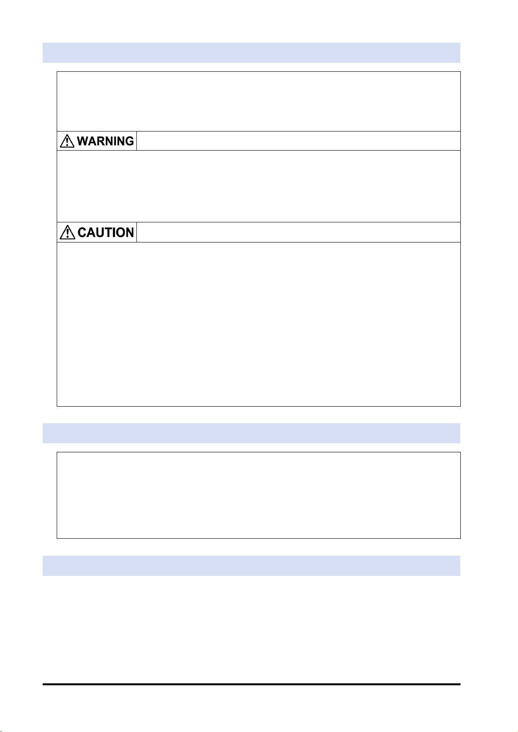
■
Originator and Target
In each connection (communication line) of cyclic communication, there are "originator" which
opens each connection and "target" which a connection is opened.
The PLC (FP0H) can be set as the both originator and target.
For the communication between the FP0H and a PLC, the settable connection is "Input Only"
(i.e. data can be sent in one direction, from target to originator). By using two connections, data
can be sent and received.
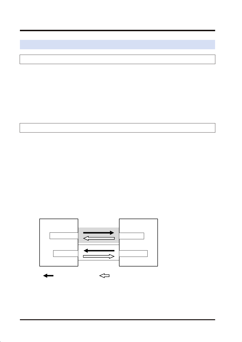
For the communication between the FP0H and other I/O devices, the FP0H is the originator.
According to devices, the data transmissions by "Input Only" (from target to originator) and
"Exclusive Owner" (two-way) may be available.
1-2 WUME-FP0HEIP-05
Page 13
FP0H
Connection
Input Only
: Opens connection. : Sends cyclic data.
I/O device
Originator
Target
FP0H
Connection
Exclusive Owner
I/O device
Originator
Target
1.1 What is EtherNet/IP?
WUME-FP0HEIP-05 1-3
Page 14
1.2 Names and Functions of Parts
1.2 Names and Functions of Parts
1.2.1 Control Unit
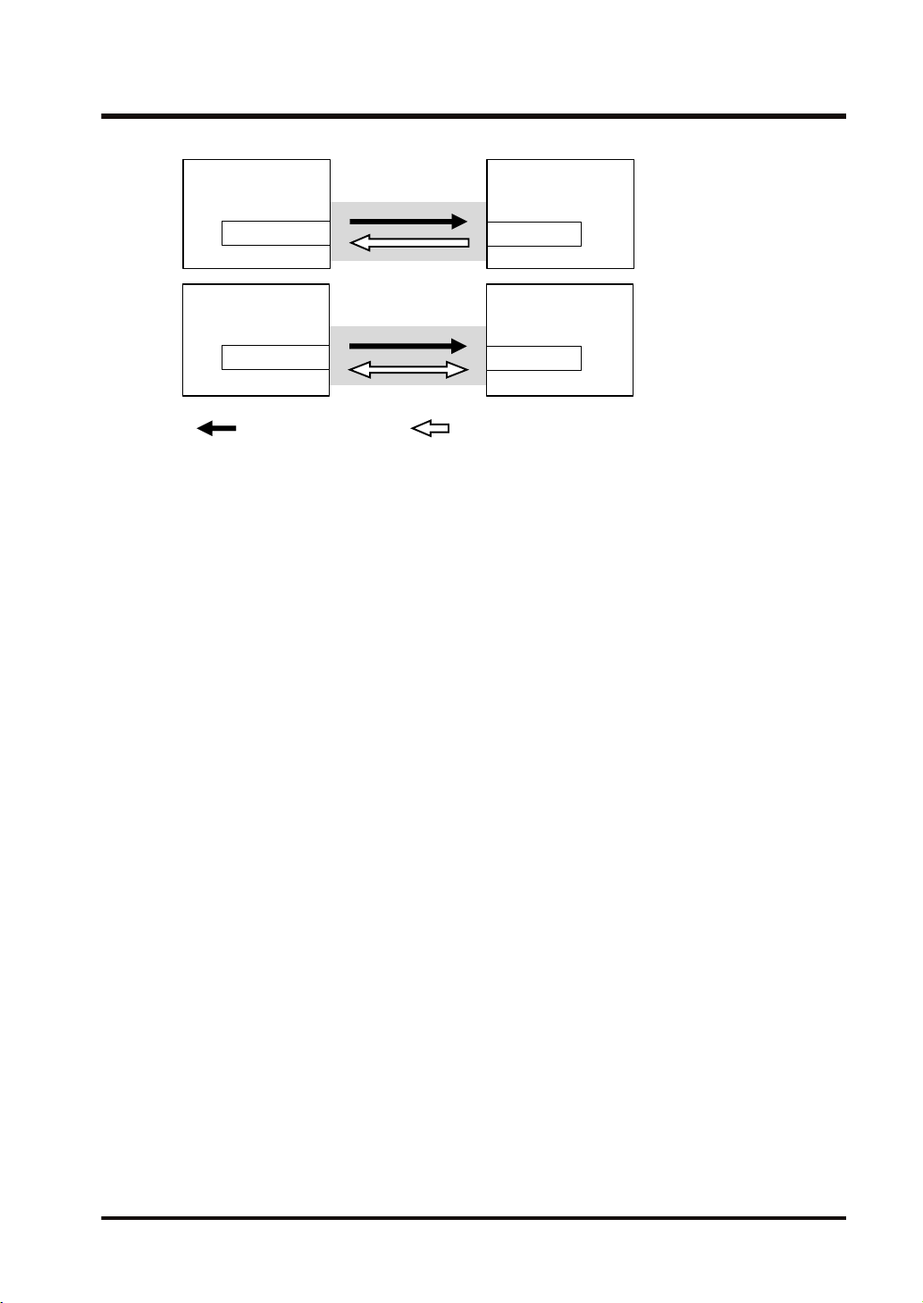
■
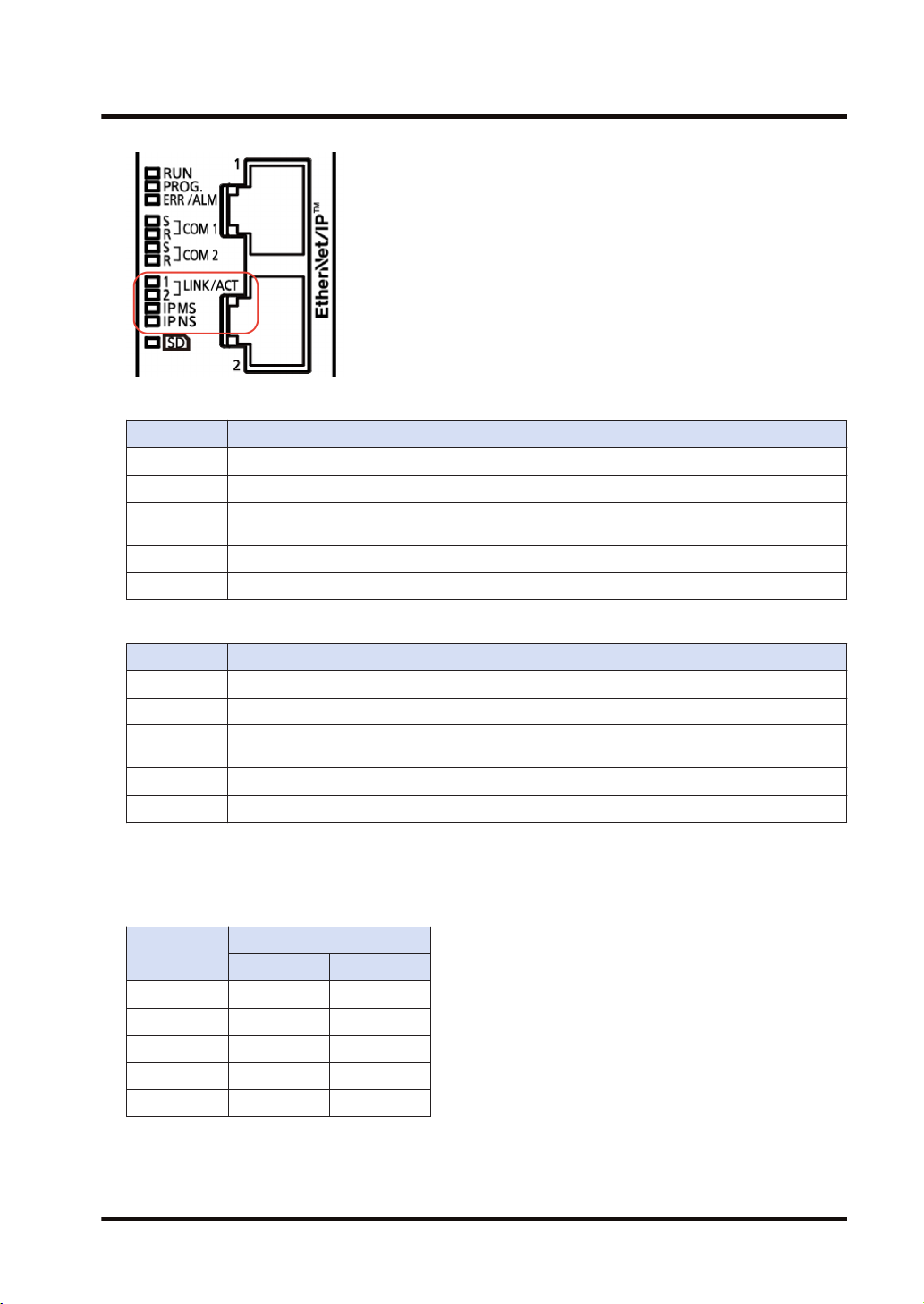
Names and Functions of Parts
Numb
er
Name Description
(1) LAN port
Operation monitor
(2)
LED
It is mounted to the FP0H Control Unit (Ethernet type). It is used for connecting
to Ethernet and EtherNet/IP.
The IP address and MAC address are common to the LAN ports 1 and 2. The
wiring can be simplified by using the two ports.
The MAC address is printed on the side face of the unit.
IP MS: Displays the operating condition of the unit.
IP NS: Displays the communication status of network.
1.2.2 LED Displays When PLC Operates
The state of the PLC can be confirmed from the lighting state of the LEDs when the PLC is
operating. The PLC states indicated by the LEDs are as follows.
1-4 WUME-FP0HEIP-05
Page 15
1.2 Names and Functions of Parts
MS (Module status indicator) <Green/Red>
LED display PLC state
LED OFF The EtherNet/IP function is disabled.
Green ON The EtherNet/IP function is normally activated.
Green
Flashing
Red ON Unrecoverable fault occurs.
Red Flashing Recoverable fault occurs. (such as a setting that load factor exceeds)
This state does not exist.
NS (Network status indicator) <Green/Red>
LED display PLC state
LED OFF The EtherNet/IP function is disabled or IP address is not established.
Green ON More than one connection is established.
Green
Flashing
Red ON IP address duplication is detected.
Red Flashing This state does not exist.
■
LED displays when PLC is started
Connection is not established, but IP address is acquired.
The MS and NS LEDs turn on in the following order when the FP0H is started.
Each lighting time of the lighting order 1 to 4 is 0.25 seconds.
Lighting
order
1 Green ON OFF
2 Red ON OFF
3 Green ON Green ON
4 Green ON Red ON
5 Green ON OFF
Lighting state
MS NS
WUME-FP0HEIP-05 1-5
Page 16
1.3 Restrictions
1.3 Restrictions
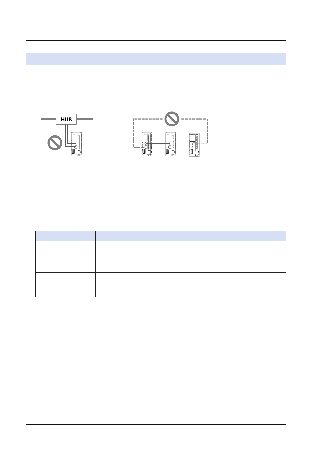
■
Connecting to External Devices
LAN ports 1 and 2 have the same IP address and MAC address.
● Do not connect the cables from the two LAN ports to the same switching HUB.
● When performing daisy chain connection, do not connect devices in a ring shape.
■
Number of connections
For the FP0H, the total number of connections of Ethernet communication and EtherNet/IP
communication should be 9 or less. For the details of the setting of the number of connection,
refer to "3.2.1 Ethernet Settings".
(The no. of user connections of Ethernet communication) + (EtherNet/IP communication) 9
connections
■
Restrictions by FP0H specifications
Item Specifications
RPI 1 to 10000 ms (In 0.5 ms unit)
Cyclic communication
allowable
communication band
Usable devices WX, WY, WR, WL, DT, LD
Device specification of
each tag/instance
5000 pps (Packet size: 2 to 510 bytes)
2500 pps (Packet size: 511 to 1450 bytes)
Max. 8 devices
1-6 WUME-FP0HEIP-05
Page 17

2 Cyclic Communication
2.1 Cyclic Communication Function..........................................................2-2
2.1.1 Overview of Cyclic Communication ................................................. 2-2
2.1.2 Operation of Cyclic Communication................................................. 2-3
2.1.3 Data Refresh of Cyclic Communication ........................................... 2-3
2.1.4 Data Area Specifications Using Tag/Instance .................................. 2-4
2.2 Cyclic Communication of FP0H ..........................................................2-6
2.2.1 Connection using FP0H as originator .............................................. 2-6
2.2.2 Connection Using FP0H as Target................................................... 2-7
2.2.3 Example of Configuration When FP0H is Originator and Target...... 2-7
WUME-FP0HEIP-05 2-1
Page 18
Opens connections.
PLC PLC
I/O device
Originator
Target
Cyclic communication
PLC PLC
I/O device
Originator
Target
2.1 Cyclic Communication Function
2.1 Cyclic Communication Function
2.1.1 Overview of Cyclic Communication
The cyclic communication is a function to perform data transmission with constant intervals
(RPI) between PLC and PLC or PLC and I/O device on the EtherNet/IP network.
In the cyclic communication, one device opens a communication line which is called connection
for a destination device. The side which opens the connection (communication line) is called
"originator", and the side which the connection is opened is called "target".
Connection information on the cyclic communication is set in the originator. The originator
connects to the target according to the connection information. The tag/instance required for the
connection from the originator is registered in the target.
Once the connection is open, the cyclic communication begins according to the settings of the
connection information.
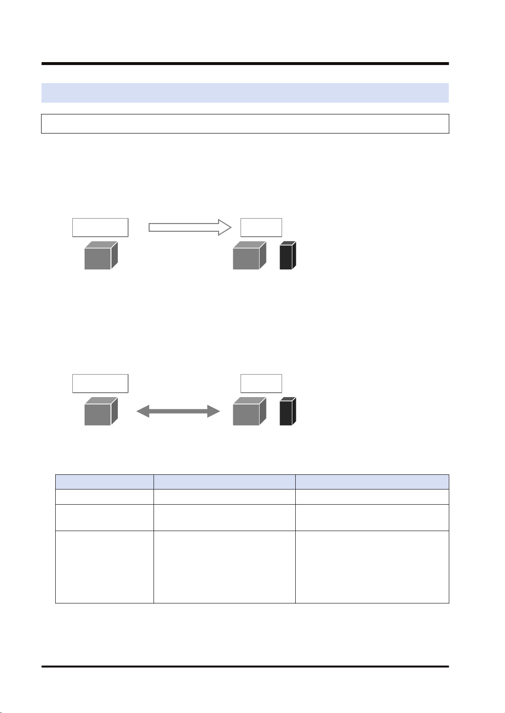
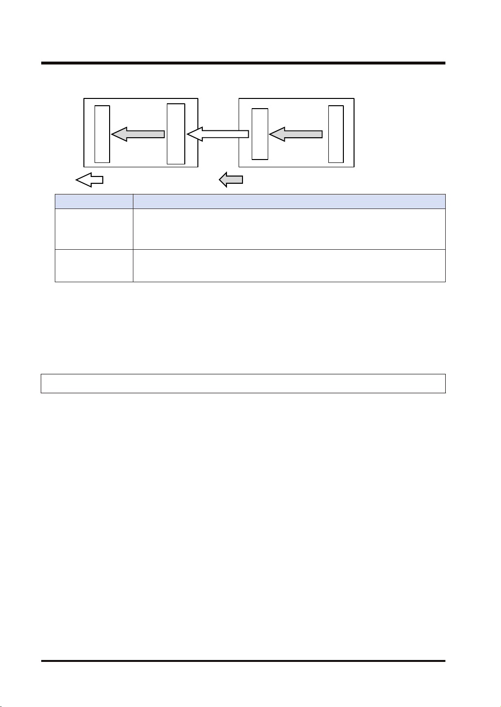
Comparison of originator and target
Item Originator Target
Applicable model PLC PLC, I/O device
When starting
communication
Connection information
2-2 WUME-FP0HEIP-05
Opens connections.
(Connects to targets.)
Target connection information
● IP Address
● Tag/Instance
Cyclic communication information
● RPI
● Communication method, etc.
Connection is opened.
(Connected from originator.)
Connected from originator
● Tag/Instance
Page 19
Send buffer
Receive buffer
Data area
Receive buffer
Send buffer
Data area
Input Only
Exclusive Owner
: Sends cyclic data. : Refreshes data.
Receive buffer
Send buffer
Data area
Data area
Originator
Target
2.1 Cyclic Communication Function
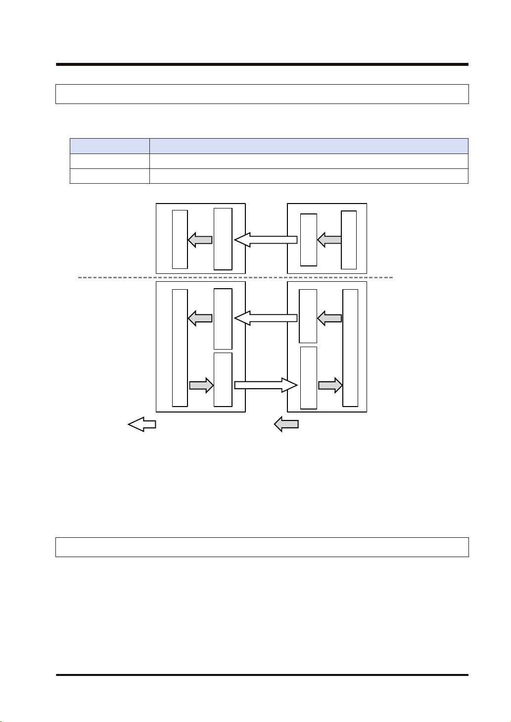
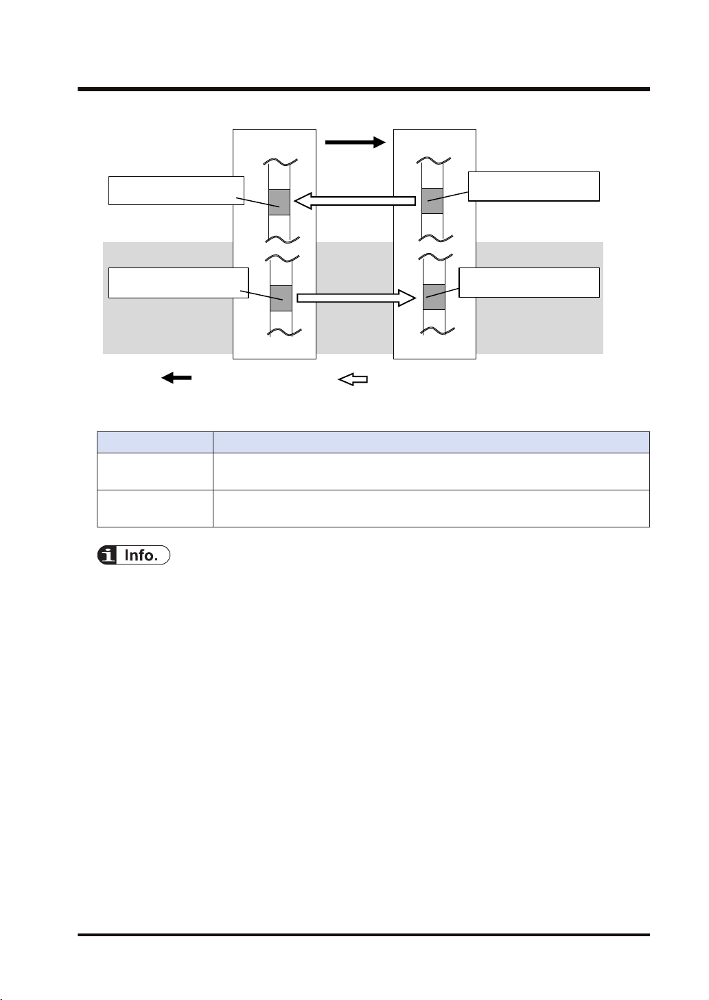
2.1.2 Operation of Cyclic Communication
The communication behavior in the cyclic communication varies according to the settings of
connections.
Description
Input Only Data is sent in the input direction only (From target to originator)
Exclusive Owner Data is sent bi-directionally.
(Note 1) The transfer operations Data area>Send buffer and Receive buffer>Data area in each device are
● For some target devices, "Exclusive Owner" setting is not available.
● When PLCs including FP0H are set as targets, "Input Only" setting is only available.
● For sending/receiving data between PLC and PLC, it is necessary to use two connections
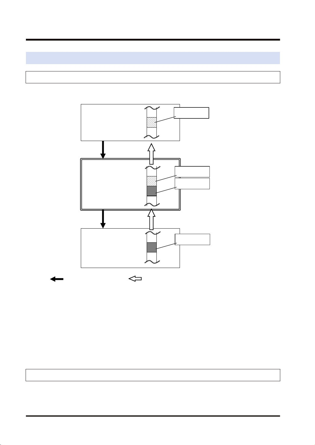
2.1.3 Data Refresh of Cyclic Communication
In the cyclic communication, data is refreshed in synchronization with operation cycle and RPI.
The refresh of sent data and received data is controlled for each RPI.
WUME-FP0HEIP-05 2-3
called "Refresh".
and open them each other.
Page 20
Send buffer
Receive buffer
Data area
: Sends cyclic data. : Refreshes data.
Data area
Input
refresh
Output
refresh
<Receiver side>
<Sender side>
2.1 Cyclic Communication Function
Refresh direction Refresh operation
In refresh processing at the beginning of scan, if there is incoming data in the receive
Input refresh
Output refresh
■ Refresh operation when starting communication
● After confirming that the connection is open with the connection open flag, refreshes sent
data.
● After detecting received data with the received data existence flag, refreshes received data.
● After refreshing received data, the normal reception active flag turns ON.
buffer for the cyclic communication, it is copied to the operation memory. After the
completion of the refresh operation, the latest received data will be an object to be
refreshed in the next time.
In refresh processing at the beginning of scan, if there is space in the send buffer for the
cyclic communication, it is copied from the data area. If the refreshing has not been
completed at the time of data transmission, the previous refreshed data is sent.
2.1.4 Data Area Specifications Using Tag/Instance
In the cyclic communication, the data send and received areas are specified using "Tag" or
"Instance".
● For "Tag", the areas are specified by symbols. For "Instance", they are specified by numbers.
● For some target devices, only either of "Tag" and "Instance" may be available.
● In the connection of "Exclusive Owner", the receive area of each target is specified by
another tag or instance.
(Note) Even when specifying by tag, numbers are assigned to packets during the actual cyclic
communication.
2-4 WUME-FP0HEIP-05
Page 21
Exclusive Owner only
TargetOriginator
: Opens connection. : Sends cyclic data.
Data area
Data area
Instance (100)
When specifying "Instance"
Tag (Tag_1)When
specifying "Tag"
Tag (Tag_1)
When specifying "Tag"
Instance (100)
When specifying "Instance"
Settings of target and originator
Settings
Originator
Target
Tag/Instance of connected target
Data area/size of originator corresponds to Tag/Instance
Tag/Instance connected from originator
Data area/size of target corresponds to Tag/Instance
2.1 Cyclic Communication Function
● In each connection, the sizes of the data areas which correspond to the originator and target
should be the same.
● For the FP0H, the data areas of each connection can be allocated to the operation memories in
a maximum of 8 areas. Device names that can be allocated are WX, WY, WR, WL, LD, and DT.
For the automatic allocation, the WL and LD areas are used.
WUME-FP0HEIP-05 2-5
Page 22
Low-order PLC
Input Only
I/O device
Exclusive Owner
Target 1 Target 2
Connection 1
Receiving data
FP0H
Connection 2
Sending/Receiving data
Originator
2.2 Cyclic Communication of FP0H
2.2 Cyclic Communication of FP0H
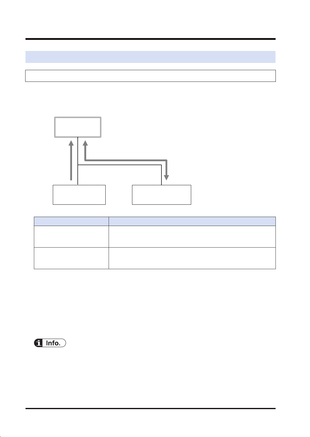
2.2.1 Connection using FP0H as originator
■
Illustration of operation
The FP0H establishes connections with targets registered in Scan List and performs the cyclic
communication.
Description
Input direction
(Direction from Target to
Originator)
Output direction
(Direction from Originator to
Target)
■
Settings
Data is sent from targets to the FP0H periodically.
Data is sent from the FP0H to targets periodically.
Register target low-order PLCs and I/O devices in "Scan List" of FP0H and register connection
information. The registration is made for each target.
Register the following information in the connection information.
● Connected target information (IP address, Tag/Instance)
● Data area and size that corresponds to Tag/Instance
● Cyclic communication information (RPI, Communication method)
● Scan List is a list for setting the connection information with "Target". Use Programming
software FPWIN GR7 for the registration.
● For registering other companies' EtherNet/IP devices in Scan List, the EDS files of those
devices are required. Communication parameters that can be set in each device are defined in
the EDS files.
2-6 WUME-FP0HEIP-05
Page 23
High-order PLC
(FP7)
Originator
Connection 1
Sends data to High-order PLC.
FP0H
Input Only
Target
2.2 Cyclic Communication of FP0H
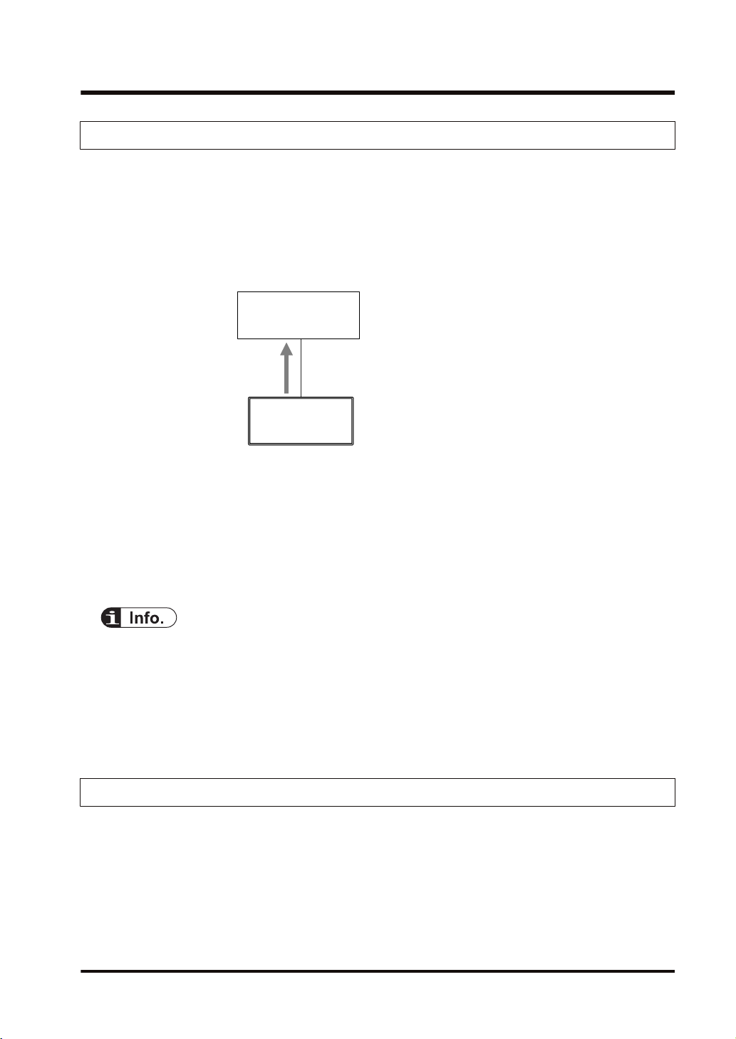
2.2.2 Connection Using FP0H as Target
■
Illustration of operation
● The high-order PLC (FP7) (originator) makes a connection for the registered tag/instance.
● When the FP0H is used as target, only the transmission to originator (Input Only) is
available.
● Once the connection from an originator is established, the FP0H sends data to the originator
from the buffer for the cyclic communication periodically.
■
Settings
Register the tag/instance information in the "I/O map" of the FP0H.
● The tag/instance information is registered for each originator.
● The tag/instance information includes the following information.
• Connected tag/instance
• Data area and size that corresponds to Tag/Instance
● I/O map is a list for setting the connection information with "Originator". Use Programming
software FPWIN GR7 for the registration.
● The EDS file of FP0H can be downloaded from our download center.
https://industrial.panasonic.com/ac/j/dl_center/
● For using the FP0H as a target, the both methods, tag and instance, are available. However,
the selectable instance IDs for the instance method are 100 to 199.
2.2.3 Example of Configuration When FP0H is Originator and Target
■
Illustration of operation
Example of Configuration When FP0H is Originator and Target In the example, the FP0H uses
five connections.
WUME-FP0HEIP-05 2-7
Page 24
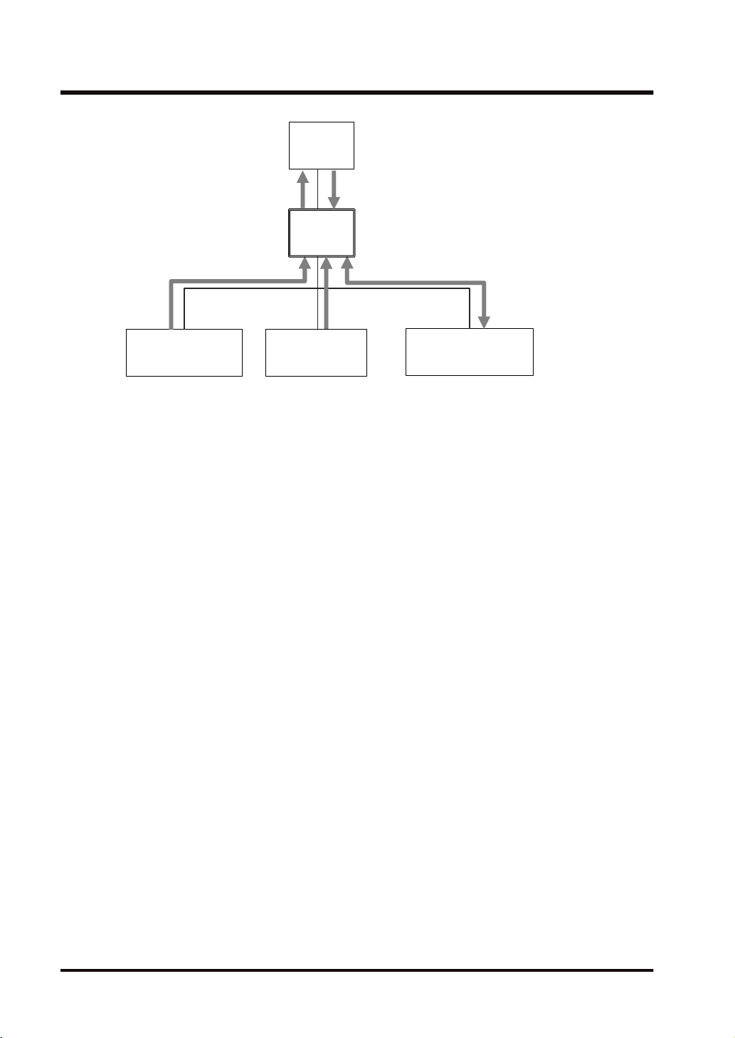
FP7
Target 1
Low-order PLC
Input Only
I/O device B
Exclusive Owner
Target 2 Target 3
Target 4
Connection 1
Sends data to FP7.
Connection 2
Sends data from FP7.
Connection 3
Receives data.
Connection 4
Receives data.
Connection 5
Sends and Receives data.
FP0H
FP0H
I/O device A
Input Only
Originator 1
2.2 Cyclic Communication of FP0H
■
Target settings
Set the FP0H as below to send/receive data with the high-order FP7.
● Register the FP7 in the scan list and set the connection information.
● Register the I/O map for connecting the FP7 and set the tag/instance information.
■
Originator settings
Set the FP0H as below to receive data from low-order devices (low-order PLC, I/O devices A
and B). When the connection with a target is "Exclusive Owner", data can be sent and received.
● Register the low-order PLC, I/O devices A and B in the scan list and set the connection
information.
2-8 WUME-FP0HEIP-05
Page 25

3 Setting Procedure
3.1 Overview of Settings...........................................................................3-2
3.1.1 System Example .............................................................................. 3-2
3.1.2 Setting Procedure ............................................................................ 3-2
3.2 Initial Setting of Ethernet /IP ...............................................................3-4
3.2.1 Ethernet Settings ............................................................................. 3-4
3.2.2 Starting EtherNet/IP Setting Screen ................................................ 3-5
3.2.3 EtherNet/IP Basic Configuration ...................................................... 3-5
3.2.4 Items of Ethernet /IP Basic Configuration ........................................ 3-6
3.3 Settings of Connection Using FP0H as Originator..............................3-8
3.3.1 Settings ............................................................................................ 3-8
3.3.2 Registering EDS File of Target Device............................................. 3-8
3.3.3 Adding Target in Scan List ............................................................... 3-9
3.3.4 Setting IP Address of Target ............................................................ 3-10
3.3.5 Setting Tag/Instance ........................................................................ 3-11
3.3.6 Specifying Data Area Corresponding to Tag/Instance ..................... 3-13
3.3.7 Reference: Setting of Target "FP0H(B)"........................................... 3-15
3.4 Settings of Connection Using FP0H as Target ...................................3-16
3.4.1 Settings ............................................................................................ 3-16
3.4.2 Adding I/O Map to Scan List ............................................................ 3-16
3.4.3 Registering Tag Name/Instance ID .................................................. 3-17
3.4.4 Registering Data Area Corresponding to Tag/Instance.................... 3-18
3.4.5 Reference: Setting of Originator "FP7" ............................................ 3-19
3.5 Confirmation of Load Factor Calculation.............................................3-21
3.5.1 Load Factor Calculation ................................................................... 3-21
3.5.2 Displaying Load Factor Calculation ................................................. 3-21
3.6 Saving EtherNet/IP Settings ...............................................................3-22
3.6.1 Saving EtherNet/IP Settings in Project ............................................ 3-22
3.6.2 Saving/Reading EtherNet/IP Settings in File ................................... 3-22
3.6.3 Writing EtherNet/IP Settings to FP0H .............................................. 3-23
WUME-FP0HEIP-05
3-1
Page 26
: Opens connection. : Sends cyclic data.
FP0H(A)
IP:192.168.1.5
LD40
LD49
LD40
LD49
LD30
LD39
FP0H(B)
FP7
LD30
LD39
IP:192.168.1.6
IP:192.168.1.7
Originator
Originator
Target
Target
Tag_Test2
Tag_Test1
Tag_Test2
Tag_Test1
3.1 Overview of Settings
3.1 Overview of Settings
3.1.1 System Example
This chapter describes the case of setting FP0H(A) in the following system example.
Operation of FP0H(A)
● The data received from the Tag (Tag_Test2) of the FP0H(B) is stored in the data area (LD40
to 49) of the FP0H(A). The FP0H(A) is the originator for the FP0H(B).
Add the FP0H(B) in the scan list and make the connection setting.
● The data stored in the data area (LD30 to 39) of the FP0H(A) is sent to the FP7. The
FP0H(A) is the target for the FP7.
Add the tag (Tag_Test1) in the I/O map and register the data area.
● The number of used connections totals two.
3.1.2 Setting Procedure
The setting procedure is as follows.
Use Programming software Control FPWIN GR7 (hereinafter referred to FPWIN GR7) for the
settings.
3-2 WUME-FP0HEIP-05
Page 27

3.1 Overview of Settings
Item Outline of operation Reference
1 Initial setting of Ethernet /IP
Settings of connection using
2
FP0H as originator
Settings of connection using
3
FP0H as target
Confirmation of load factor
4
calculation
5 Saving of Ethernet/IP settings Save the settings of EtherNet/IP. "P.3-22"
Enable EtherNet/IP communication in the "Ethernet settings"
and make the initial setting of EtherNet/IP.
Register EDS Files of target devices. "P.3-8"
Add targets in the scan list. "P.3-9"
Register connection information (such as connected targets,
cyclic communication, corresponding data areas and sizes).
Add I/O map in the scan list. "P.3-16"
Register the tag/instance information connected. "P.3-17"
Confirm the load factor calculation is 100% or less. "P.3-21"
"P.3-4"
"P.3-10"
WUME-FP0HEIP-05 3-3
Page 28
3.2 Initial Setting of Ethernet /IP
3.2 Initial Setting of Ethernet /IP
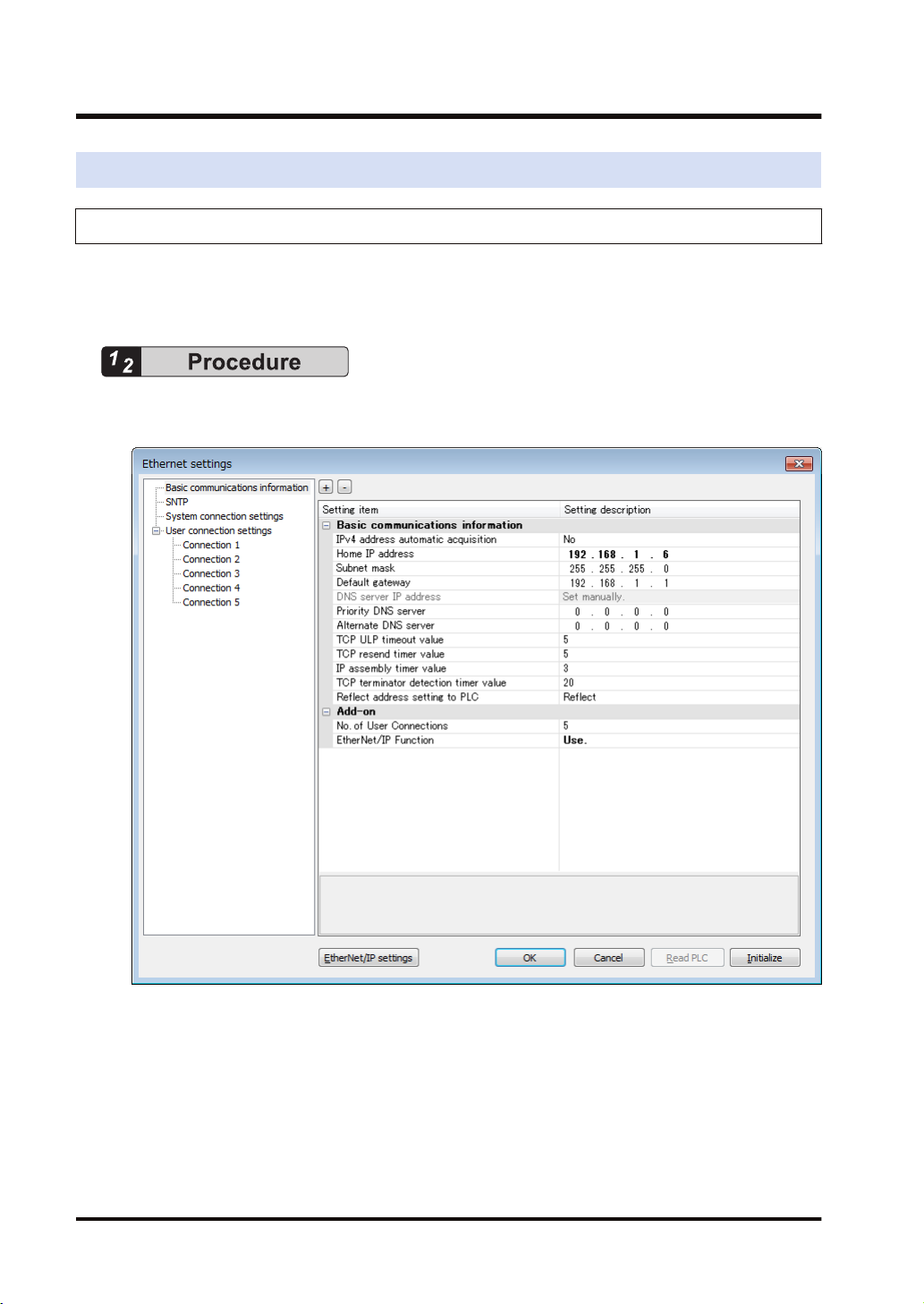
3.2.1 Ethernet Settings
This is the setting for the communication function via LAN ports including EtherNet/IP. Use
FPWIN GR7 for the setting. The following procedure is explained on the condition that FPWIN
GR7 has already started.
1. Select Option>Ethernet settings from the menu bar.
The "Ethernet settings" dialog box appears.
2. As necessary, change "Home IP address" and "No. of User Connections".
In this example, "IP address = 192.168.1.6", and "No. of User Connections = 5".
3. Change the setting of "EtherNet/IP Function" to "Use".
4. Press the [OK] button.
3-4 WUME-FP0HEIP-05
Page 29
3.2 Initial Setting of Ethernet /IP
● The number of connections available for EtherNet/IP is (9-"No. of user connection"). When the
value is "5" which is initial value, the number of connections available for EtherNet/IP is "4".
● If the setting of “EtherNet/IP Function” is changed to"" "Not use", the EtherNet/IP setting
information will be cleared.
3.2.2 Starting EtherNet/IP Setting Screen
The following procedure is explained on the condition that FPWIN GR7 has already started.
1. Select Option>EtherNet/IP Settings from the menu bar.
The EtherNet/IP setting screen appears.
The following description assumes that the EtherNet/IP setting screen has been activated.
3.2.3 EtherNet/IP Basic Configuration
Make the EtherNet/IP basic configuration. The following procedure is explained on the
assumption that the EtherNet/IP setting screen has been activated.
WUME-FP0HEIP-05 3-5
Page 30
3.2 Initial Setting of Ethernet /IP
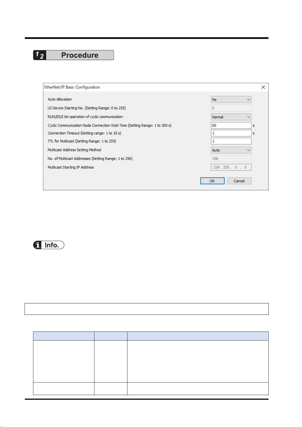
1. Select Setting>EtherNet/IP Basic Configuration from the menu bar.
The EtherNet/IP Basic Configuration dialog box appears.
2. Change "Auto Allocation", "RUN / IDLE bit operation of cyclic communication", "Connection
Timeout" as necessary.
In this example, they are set as follows: "Auto Allocation = No", "RUN/IDLE bit operation of
cyclic communication = Normal", and "Connection Timeout = 1 s".
3. Press the [OK] button.
● When allocating devices manually, set "Auto Allocation" to "No".
● For performing operation check, set "RUN/IDLE bit operation of cyclic communication" to
"Limited". When selecting "Normal", the RUN/IDLE bit of the FP0H does not turn "ON" unless
the communications with all the targets registered in the scan list are established.
● The "Connection Timeout" can be set with the unit firmware Ver.1.7 or later.
3.2.4 Items of Ethernet /IP Basic Configuration
■
Settings relating to cyclic communication operation
Item Default Description
Set whether to use the automatic allocation of devices or not (Yes/
No).
Auto Allocation Yes
LD Device Starting No. 0
Auto Allocation
"Yes":
Auto Allocation "No": Devices are allocated manually.
Set the starting device number to be allocated at the time of the
device automatic allocation.
Devices for the I/O map setting and
connection setting are automatically
allocated.
3-6 WUME-FP0HEIP-05
Page 31

3.2 Initial Setting of Ethernet /IP
Item Default Description
Default: 0 (Allocated from LD0 in sequence.)
Set the operating condition of the RUN/IDLE bit (Normal/Limited).
RUN/IDLE bit operation of
cyclic communication
■
Settings relating to abnormality judgement
Item Default Description
Cyclic Communication
Node
Connection Wait Time
Connection Timeout
(Note 1) The "Connection Timeout" can be set with the unit firmware Ver.1.7 or later.
■
Settings relating to Multicast
Item Default Description
TTL for Multicast 1
Multicast Address Setting
Method
No. of Multicast Addresses (256)
Multicast Starting IP Address (239.255.0.0)
(Note 1)
Normal
60 s
1 s Set the connection timeout period.
Auto Set "Auto" or "Specify".
"Normal": Turns on when the FP0H is in RUN mode and normally
communicating with all the targets (except FP0H)
registered in the scan list.
"Limited": Turns on when the FP0H is in RUN mode.
Set the period of time during which retry is repeated without error
determination.
Specify the number of routers that multicast transmission
packets can pass.
Set the number of multicast addresses.
This item is valid when Multicast Address Setting Method
is specified.
Set the starting IP address of multicast.
This item is valid when Multicast Address Setting Method
is specified.
■
Operation of Auto Allocation
Devices are allocated using the value specified for "LD Device Starting No." in "EtherNet/IP
Basic Configuration" as the starting device.
● Allocating order
I/O map no. 1
I/O map no. 2
:
Node 1 of scan list (Input to Output)
Node 2 of scan list (Input to Output)
:
Devices are automatically reallocated when either the scan list or I/O map is added (deleted)
and the allocated data size is changed.
WUME-FP0HEIP-05 3-7
Page 32

: Opens connection. : Sends cyclic data.
FP0H(A)
LD40
LD49
LD40
LD49
FP0H(B)
LD30
LD39
IP:192.168.1.6
IP:192.168.1.7
Originator
Target
Tag_Test2
Tag_Test2
Add in Scan List.
3.3 Settings of Connection Using FP0H as Originator
3.3 Settings of Connection Using FP0H as Originator
3.3.1 Settings
This section describes the setting method of the connection using the FP0H as originator. The
FP0H(A) in the figure below is an object for the setting.
■
Illustration of operation
Ten word data is sent from the data area (LD40 to 49) of the FP0H(B) to the data area (LD40 to
49) of the FP0H(A).
■
Settings
● Add the FP0H(B) to the scan list of the FP0H(A).
● Set the data area of FP0H(B) by specifying the tag (Tag_Test2).
● Set the data area of the own unit for the tag (Tag_Test2).
3.3.2 Registering EDS File of Target Device
When using other companies' devices as targets, their EDS files should be registered in the
EtherNet/IP setting tool. Please acquire EDS files from each vendor's website.
3-8 WUME-FP0HEIP-05
Page 33

3.3 Settings of Connection Using FP0H as Originator
Register EDS Files of target devices in "Device List".
The following procedure is explained on the assumption that the EtherNet/IP setting screen has
been activated.
1. Select EDS File>Register from the menu bar.
2. Select an EDS file to be registered from the explorer screen and press "Open".
The used target device will be added to "Device List". Once the EDS file is registered, the
registration is not required from the next time.
3.3.3 Adding Target in Scan List
Add connected targets in the scan list. The following procedure is explained on the assumption
that the EtherNet/IP setting screen has been activated.
1. Select and right-click a registered target device (in this example, FP0H CONTROL UNIT...)
from Device List.
WUME-FP0HEIP-05 3-9
Page 34

3.3 Settings of Connection Using FP0H as Originator
2. Select "Add to Scan List" from the displayed menu.
The target will be added.
● The display content of the target added to Scan List
Node no. 1
Node Name FP0H CONTROL UNIT AFP0HC32E
Connection Name Input Only (Tag type)
3.3.4 Setting IP Address of Target
Set the IP address of the target added to Scan List. The following procedure is explained on the
assumption that the EtherNet/IP setting screen has been activated.
1.
Select the node name of the target from Scan List.
3-10 WUME-FP0HEIP-05
Page 35

3.3 Settings of Connection Using FP0H as Originator
The "Device Setting" screen appears.
2. Set the "IP Address" of the target.
In this example, "IP address = 192.168.1.7".
3. Specify a node name as necessary.
In this example, "Node Name = FP0H(B)".
● Unchanging the node name does not affect the cyclic communication. The change is reflected
in Scan List. It helps to distinguish the targets of the same device.
● When setting "Valid/Invalid Flag" to "Invalid", the reservation node setting is enabled.
3.3.5 Setting Tag/Instance
Set the communication method (Tag/Instance) corresponding to the target added to Scan List.
The following procedure is explained on the assumption that the EtherNet/IP setting screen has
been activated.
1. Select the connection name from Scan List.
WUME-FP0HEIP-05 3-11
Page 36

3.3 Settings of Connection Using FP0H as Originator
The "Connection Setting" screen appears.
2. Select a communication method (Tag or Instance) in "Connection Name".
Once "Connection Name" is selected, "Communication Method" (Tag/Instance) will change.
In this example, "Connection Name = Input Only (Tag type)".
3. According to the target, change "Tag Name/Instance Name" and "Data Size".
3-12 WUME-FP0HEIP-05
Page 37

3.3 Settings of Connection Using FP0H as Originator
(Note) The Instance ID and data size are changed from "Parameter Setting".
In this example, "Tag Name = Tag_Test2", and "Data Size = 20 bytes (10 words)".
● For some targets, "Application Type" (Input Only/Exclusive Owner) can be selected from
"Connection Name".
● When "Exclusive Owner" is selected for "Application Type", specify "Output Information (O>T)"
for sending data from the originator to the target.
● Items such as "RPI" and "Input Send Trigger" can be changed in the "Connection Setting"
screen. Refer to "4.3.2 Operations in Connection Setting Screen".
3.3.6 Specifying Data Area Corresponding to Tag/Instance
For setting the data area manually, change the auto allocation to "No" in the "EtherNet/IP Basic
Configuration". When it is set to "Yes", this procedure is not required.
WUME-FP0HEIP-05 3-13
Page 38

3.3 Settings of Connection Using FP0H as Originator
The following procedure is explained on the assumption that the EtherNet/IP setting screen has
been activated.
1. Select the connection name whose setting is made from Scan List.
The "Connection Setting" screen appears.
2. Press "Add" in the Device Allocation area.
3.
Specify "Device Type", "Device No." and "Data Size", and press "Register".
3-14 WUME-FP0HEIP-05
Page 39

3.3 Settings of Connection Using FP0H as Originator
In this example, "Device Type = LD", "Device No. = 40" and "Data Size = 10".
● When "Exclusive Owner" is selected for "Application Type", specify "Output Information
(O>T)" for sending data from the originator to the target.
3.3.7 Reference: Setting of Target "FP0H(B)"
For the target FP0H(B), add the I/O map and set as follows.
Item Settings
IP Address 192.168.1.7
Communication
method
Tag Name Tag_Test2
Data Size 10 words
Tag
WUME-FP0HEIP-05 3-15
Page 40

FP0H(A)
IP:192.168.1.5
LD40
LD49
LD30
LD39
FP7
LD30
LD39
IP:192.168.1.6
Originator
Target
Tag_Test1
Tag_Test1
Set in I/O map.
3.4 Settings of Connection Using FP0H as Target
3.4 Settings of Connection Using FP0H as Target
3.4.1 Settings
This section describes the setting method of the connection using the FP0H as target, The
FP0H(A) in the figure below is an object for the setting.
■
Illustration of operation
Ten word data is sent from the data area (LD30 to 39) of the FP0H(A) to the data area (LD30 to
39) of FP7.
When the FP0H is used as target, only the data transmission to originator is available.
■
Settings
● Register a tag (Tag_Test1) specified from the FP7 (Originator) in the "I/O map".
● Set the data area (LD30 to 39) corresponding to the tag.
3.4.2 Adding I/O Map to Scan List
Add the I/O map in Scan List. The following procedure is explained on the assumption that the
EtherNet/IP setting screen has been activated.
1.
Select and right-click "I/O Map - Scheduled Connections: 0" from Scan List.
3-16 WUME-FP0HEIP-05
Page 41

3.4 Settings of Connection Using FP0H as Target
2. Select "Add I/O Map" from the displayed menu.
The I/O map will be added to Scan List.
● The display content of the I/O map added to Scan List
I/O map No. 1
Communication method Tag
Tag Name/Instance ID Tag_1
3.4.3 Registering Tag Name/Instance ID
Register the Tag Name/Instance ID specified from originator. The following procedure is
explained on the assumption that the EtherNet/IP setting screen has been activated.
1.
Select the target I/O map from Scan List.
WUME-FP0HEIP-05 3-17
Page 42

3.4 Settings of Connection Using FP0H as Target
"I/O Map Setting" screen appears.
2. Select Communication Method (Tag or Instance).
In this example, "Communication Method = Tag".
3. Input Tag Name/Instance ID.
In this example, "Tag Name = Tag_Test1".
4. Input "Data Size" of transmission data.
In this example, "Data Size = 10 words".
● Register Tag/Instance for each connected originator.
● When connected from more the one originators, the connections are distinguished by each
instance ID/tag name.
3.4.4 Registering Data Area Corresponding to Tag/Instance
For setting the data area manually, change the auto allocation to "No" in the "EtherNet/IP Basic
Configuration". When it is set to "Yes", this procedure is not required.
The following procedure is explained on the assumption that the EtherNet/IP setting screen has
been activated.
1.
Select the target I/O map from Scan List.
3-18 WUME-FP0HEIP-05
Page 43

3.4 Settings of Connection Using FP0H as Target
"I/O Map Setting" screen appears.
2. Press "Add" in the Device Allocation area.
3. Specify "Device Type", "Device No." and "Data Size", and press "Register".
In this example, "Device Type = LD", "Device No. = 30" and "Data Size = 10".
● Register Tag/Instance for each connected originator.
● When connected from more the one originators, the connections are distinguished by each
instance ID/tag name.
3.4.5 Reference: Setting of Originator "FP7"
For the originator FP7, add the FP0H in Scan List and set as follows.
Item Settings
Target IP Address 192.168.1.6
Connection Name Input Only (Tag type)
WUME-FP0HEIP-05 3-19
Page 44

3.4 Settings of Connection Using FP0H as Target
Item Settings
Tag Name Tag_Test1
Data Size 10 words
3-20 WUME-FP0HEIP-05
Page 45

3.5 Confirmation of Load Factor Calculation
3.5 Confirmation of Load Factor Calculation
3.5.1 Load Factor Calculation
The load factor is the calculated ratio of the number of actually used packets to the maximum
number of packets which the FP0H can send/receive in one second by cyclic communication.
● Packets other than by cyclic communication or unnecessary received packets are not
considered for calculating the load factor.
● Reserved nodes are not included in the calculation of load factor.
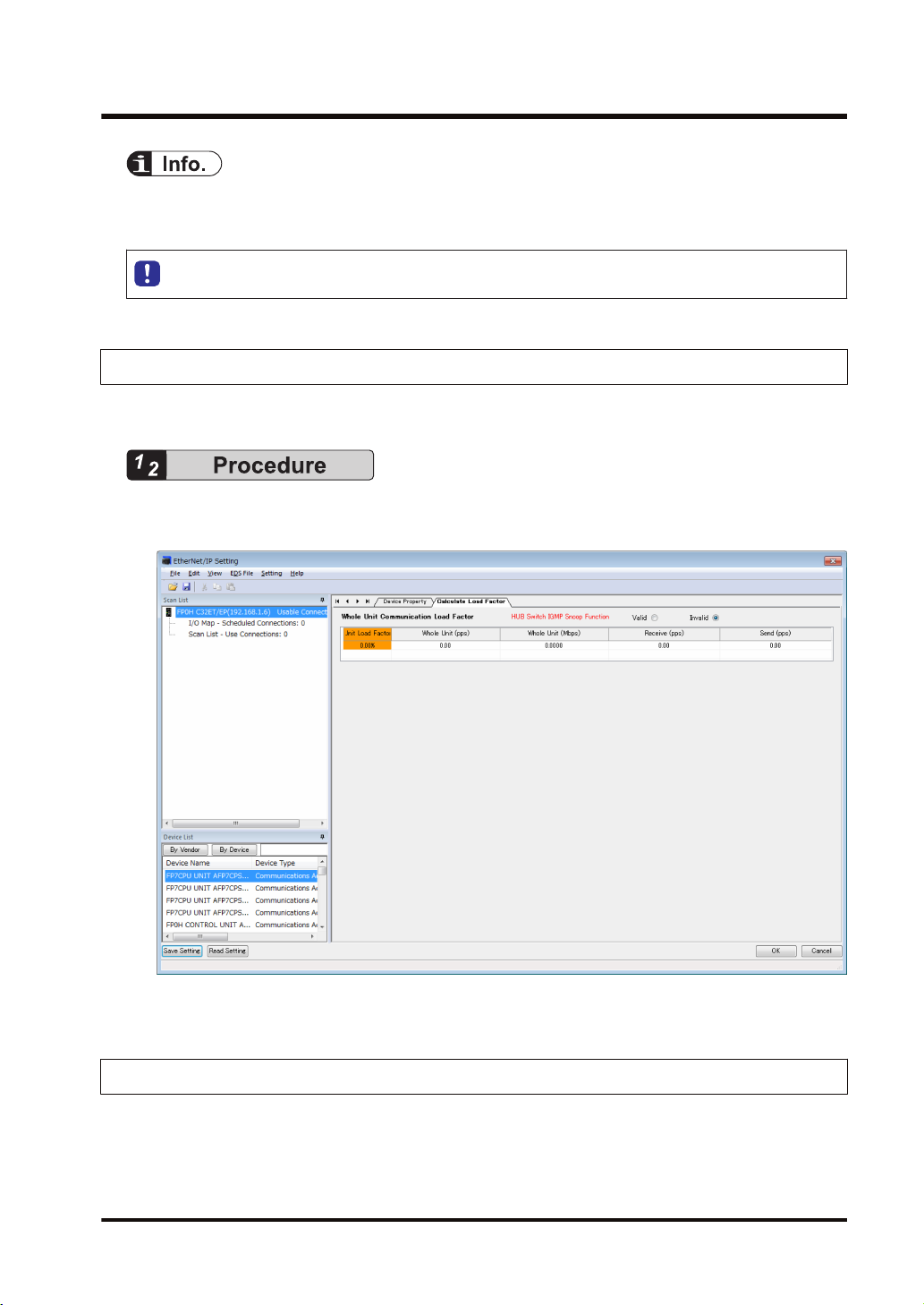
3.5.2 Displaying Load Factor Calculation
The following procedure is explained on the assumption that the EtherNet/IP setting screen has
been activated.
1. Select the uppermost "FP0H C32ET/EP(192.168.1.6) Usable Connect..." from Scan List.
The "Calculate Load Factor" window appears.
2. Confirm each load factor of the whole unit, I/O map and scan list.
Load factors for each setting of I/O map and scan list are calculated separately.
● The load factors of FP0H and each target should be 100% or less.
WUME-FP0HEIP-05 3-21
Page 46

3.6 Saving EtherNet/IP Settings
3.6 Saving EtherNet/IP Settings
3.6.1 Saving EtherNet/IP Settings in Project
The following procedure is explained on the assumption that the EtherNet/IP setting screen has
been activated.
Press the [OK] button on the lower right of the screen.
1.
3.6.2 Saving/Reading EtherNet/IP Settings in File
Save and read the settings specified in the EtheNet/IP Setting screen into a separate file from
the project file. The saved EtherNet/IP settings can be reused in multiple units and projects.
The following procedure is explained on the assumption that the EtherNet/IP setting screen has
been activated.
3-22 WUME-FP0HEIP-05
Page 47

3.6 Saving EtherNet/IP Settings
1. Press "Save Settings" on the lower left of the EtherNet/IP Setting screen.
The saving destination and file names appear.
(The same operation is performed when selecting "File" from the menu bar.)
2. Enter a saving destination and file name, and press [Save] button.
The settings specified in the EtherNet/IP Setting screen will be saved as a file whose
extension is ".fp0heip".
● Closing the window with the "X" mark or "Cancel" on the lower right of the window
cancels and stops the operation.
3.6.3 Writing EtherNet/IP Settings to FP0H
Transfer the settings specified in the EtherNet/IP Setting screen to the FP0H.
The following procedure is explained on the condition that FPWIN GR7 has already started.
1. Select Online>Download To PLC from the FPWIN GR7 menu bar.
The EtherNet/IP settings will also be downloaded to the control unit along with information
on programs, comments and system registers.
WUME-FP0HEIP-05 3-23
Page 48

(MEMO)
3-24 WUME-FP0HEIP-05
Page 49

4 Tool Operation
4.1 Scan List Window ...............................................................................4-2
4.1.1 Display Contents of Scan List Window ............................................ 4-2
4.1.2 Operations in Scan List Window ...................................................... 4-3
4.2 Device List Window.............................................................................4-7
4.2.1 Display Contents of Device List Window ......................................... 4-7
4.2.2 Operations from EDS File Menu...................................................... 4-7
4.3 Various Setting Screens......................................................................4-9
4.3.1 Operations in Device Setting Screen ............................................... 4-9
4.3.2 Operations in Connection Setting Screen........................................ 4-9
4.3.3 Operations in I/O Map Setting Screen ............................................. 4-12
4.3.4 Display Contents of Calculate Load Factor Screen ......................... 4-13
4.3.5 Display Contents of Device Property Screen................................... 4-15
4.3.6 Switching Tabs in Each Setting Screen ........................................... 4-16
WUME-FP0HEIP-05
4-1
Page 50

4.1 Scan List Window
4.1 Scan List Window
4.1.1 Display Contents of Scan List Window
The information displayed in Scan List is as follows.
Item Description
(1) Own unit
(2) No. of I/O maps
(3) Each I/O map
(4) No. of nodes
Each
(5)
connection
Shows the product name, (IP address) and the number
of usable connections.
No. of usable connection = "No. of connections
allocated to Ethernet/IP" - "No. of set connection".
No. of tags/instances registered in I/O map
This number should be same as the number of
originators to be connected to the FP0H.
Tags/instances registered in I/O map
For Tag
Shows the registered number and Tag (tag name).
For Instance
Shows the registered number and Instance (instance
ID).
No. of connections registered in Scan List
Shows the number of targets to be connected to the
FP0H.
Targets and connections registered in Scan List
The display contents are as follows.
Upper line
Shows a node number and node name.
Lower line
Shows a connection name.
Window display when
selected
The "Calculate Load
Factor" window appears.
(Refer to "P.4-13".)
-
"I/O Map Setting" screen
appears. (Refer to
"P.4-12".)
-
Upper line
The "Device Setting"
screen appears. (Refer to
"P.4-9".)
Lower line
The "Connection Setting"
screen appears. (Refer to
"P.4-9".)
4-2 WUME-FP0HEIP-05
Page 51

4.1 Scan List Window
4.1.2 Operations in Scan List Window
Scan List can be edited by selecting and right-clicking an item in Scan List.
Available operations vary according to the selected item.
■
When selecting the home unit
Display item Description
Device Property Shows the device property of the home unit.
■
When selecting the number of I/O maps
Display item Description
Add I/O Map Add an I/O map.
WUME-FP0HEIP-05 4-3
Page 52

4.1 Scan List Window
■
When selecting each I/O map
Display item Description
Delete I/O Map The selected I/O map is deleted from Scan List.
Reallocate Device Devices are reallocated from the selected I/O map downward. (The
target is I/O map only.)
By specifying the LD device starting number, devices are automatically
reallocated.
■
When selecting the number of nodes
Display item Description
Delete All All nodes added to Scan List are deleted.
Paste The copied node is pasted at the end of Scan List.
4-4 WUME-FP0HEIP-05
Page 53

4.1 Scan List Window
■
When selecting each node
Display item Description
Add Connection Connections are added to the selected node.
Depending on target devices, more than one connection can be established for one
node.
Delete The selected node is deleted from Scan List.
Delete All All nodes added to Scan List are deleted.
Rearrange Scan List Scan list is rearranged from the selected node downward.
By specifying the starting number of node number and IP address, it is rearranged.
Reallocate Device For only Scan List, devices are reallocated from the selected node downward
By specifying the LD device starting number, devices are automatically reallocated.
Copy The selected node is copied.
Cut The selected node is cut.
Paste The copied node is pasted after the selected node.
Device Property The device property of the selected node is displayed.
Device Setting The device setting of the selected node is displayed.
WUME-FP0HEIP-05 4-5
Page 54

4.1 Scan List Window
■
When selecting each connection
Display item Description
Edit Connection The connection setting of the selected connection is displayed.
Delete Connection When there are more than two connection for one node, the selected
Device Property The device property of the selected connection is displayed.
Device Setting The device setting of the selected connection is displayed.
connection is deleted.
4-6 WUME-FP0HEIP-05
Page 55

4.2 Device List Window
4.2 Device List Window
4.2.1 Display Contents of Device List Window
The display contents of the Device List window are as follows.
Display item Description
By Vendor Sorts registered EDS files by vendor.
By Device Sorts registered EDS files by device type.
Find Displays only the EDS files found by pressing the button after entering a retrieval word.
Display All Clears retrieval results and displays all registered EDS files.
List of registered
devices
All devices whose EDS files have been registered are displayed in the EtherNet/IP
Setting screen.
4.2.2 Operations from EDS File Menu
Select and right-click the device name to be operated from Device List.
(Or select "EDS File" from the menu bar.)
Display item Description
Register EDS File A new EDS file is registered in Device List.
Delete EDS File The EDS file of the selected device is deleted.
Edit EDS File
Comment...
WUME-FP0HEIP-05 4-7
A comment can be added to the EDS file of the selected device.
Page 56

4.2 Device List Window
Display item Description
Add to Scan List The selected device is added to Scan List.
Device Property The "Device Property Information" defined in the EDS file of the selected device can
Import Device Data
Base...
Export Device Data
Base...
be confirmed.
The device database (EDS file list information registered in Device List) can be
imported.
(Note)
Always save the EtherNet/IP setting before the import operation. Because the
EtherNet/IP setting is terminated after the import operation, the information in the
middle of change operation will be cleared.
Specify the folder in which the device database to be imported is stored. After the
completion of the import, the EtherNet/IP Setting screen is automatically terminated.
Restart the EtherNet/IP Setting.
The device database (EDS file list information registered in Device List) can be
exported (stored).
Select an storage folder for the device data base from the explorer.
As registered EDS files, icon files, device database files are output to the selected
folder, specify an empty folder for the storage destination.
4-8 WUME-FP0HEIP-05
Page 57

4.3 Various Setting Screens
4.3.1 Operations in Device Setting Screen
The operations of "Device Setting" are as follows.
Item Default Description
Set whether to make the communication with nodes valid or
Valid/Invalid Flag Valid
Node Name
IP Address
Product name registered in
the EDS file
Automatically acquired
when adding the target in
Scan List
invalid.
When set to Invalid, the device is set as a reserved device and
exempt from the communication.
Specify the node name of the device.
The specified node name is displayed in Scan List.
Set the IP address of the target. It can be set arbitrarily.
4.3 Various Setting Screens
4.3.2 Operations in Connection Setting Screen
The operations of "Connection Setting" are as follows.
WUME-FP0HEIP-05 4-9
Page 58

4.3 Various Setting Screens
(1) Common information
Item Description
Node Name Shows the node name of the target. The node name can be changed in "Device Setting".
Device Name Shows the device name of the target.
Select from the connection settings registered in EDS files.
Connection Name
Application Type
Compatibility Check
Communication
method
Timeout Period
Input Send Trigger
COS Transmission
Disable Time
Parameter setting
When the target is FP0H, the communication method (Tag or Instance) can be selected.
Tag: Input Only (Tag type) / Instance: Input Only (ID type)
Depending on target devices, select the application type.
The application type of a selected connection setting is displayed.
Example) Exclusive Owner, Input Only
Set the operation method of "Compatibility Check" which check the information of the
connected target device against the revision of the EDS file.
Select from Check, Not Check and Follow Adapter (Target) Rule.
Shows the set communication method (Tag/Instance).
Set the communication timeout period of cyclic communication. In the cyclic
communication, transmission data is sent as UDP packet. The timeout is judged on a
receiver side. The timeout period should be 10 msec or more.
RPI can be specified for T>O direction and O>T direction separately, so each timeout
period may be different values.
The timeout period is selected from the range of 4 (RPI x 4), 8 (RPI x 8), 16 (RPI x
16), .... 256 (RPI x 256) and 512 (RPI x 512) times of RPI.
The timing that the target sends data is selected from Cyclic or COS (Change of state).
COS is basically a cyclic communication, however, it also performs transmission when
sent data changes.
Some devices do not support COS. The FP0H does not support COS.
Transmission disable time (RPI of input information x 1/4) is displayed when "Input Send
Trigger" is set to "Change of State (COS)".
Even if the unit detects the change in data, it is not sent within the transmission disable
time.
Parameter setting window appears by pressing the [Parameter Setting] button.
Following screen is example of FP0H.
4-10 WUME-FP0HEIP-05
Page 59

Item Description
4.3 Various Setting Screens
Parameters defined in the EDS file can be set.
● The data size of Input Information (T>O) or Output Information (O<T) can be
changed.
● The instance ID can be changed (Only for target devices that can be changed).
● Others (Defined in the EDS file)
(2) Input Information (T>O): Target to Originator
(Output Information (O>T): Originator to Target *Available for Exclusive Owner only)
Item Description
RPI
Connection Type
Tag Name/Instance
ID
Data Size Shows the data size entered in "Parameter Setting"" in word unit.
Device Allocation
Set the transmission interval for the cyclic communication.
The usable RPI range depends on target devices.
Select a communication method that is selectable for the selected connection.
Point to Point / Multicast
The items vary according to the communication method of each connection.
● For "Tag": Set a tag name.
● - For "Instance": The instance ID is displayed. (It cannot be changed.)
* For allocating devices manually, set "Auto Allocation" in "EtherNet/IP Basic
Configuration" to "No".
It is possible to "Add", "Edit" or "Delete" devices allocated in the send area or receive
area.
The data size is changed in "Parameter Setting".
(The details are as follows.)
WUME-FP0HEIP-05 4-11
Page 60

4.3 Various Setting Screens
(3) Device Allocation
Up to eight device allocations can be registered for send or receive of each connection. The
maximum number of words that is available for device allocation is 16k words in total.
(Allocation cannot be performed beyond 16,384 words.)
When selecting "Add" or "Edit"), the following settings are available.
Item Description
No. Shows the device registration number.
Device Type Select Device Type from WX, WY, WR, WL, DT and LD.
Device No. Set the starting number of the device.
Data Size: Set the data size secured from the device number.
(Example) When Device Type is "WL", Device No. is "20" and Data Size is "20",
WL20 to 39 are secured as the device allocation area.
Offset Set "Offset" when allocating devices after no.2.
(Example) When the data size of device no.1 is "20 words", the data size of device no.2
is "10 words" and the data size of device no.3 is "10 words",
Set the offset of device no.2 to "20 words" and the offset of device no.3 to "30 words".
4.3.3 Operations in I/O Map Setting Screen
The operations in "I/O Map Setting" are as follows.
4-12 WUME-FP0HEIP-05
Page 61

Item Description
I/O Map No. Shows the I/O map number currently being set.
Communication
method
Tag Name/
Instance ID
Data Size Set the data size sent to originator.
Device Allocation
Set the communication method (Tag/Instance) with originator.
Set a tag name when Communication Method is set to Tag.
Set the instance ID Communication Method is set to Instance.
* For allocating devices manually, set "Auto Allocation" in "EtherNet/IP Basic
Configuration" to "No".
It is possible to "Add", "Edit" or "Delete" devices allocated in the send area. (Refer to "P.
4-12".)
4.3 Various Setting Screens
The following items are used only for the load factor calculation. In the actual communication,
the settings specified for originator are used.
Item Description
Scheduled Number
of Connected Units
Scheduled
Connected RPI
Multicast
Communication
Set the scheduled number of connections from other originators. (Only when setting
"Multicast Communication" to "Yes")
Set an RPI value to be used when connecting originators.
Set Multicast Communication (Yes/No).
4.3.4 Display Contents of Calculate Load Factor Screen
The display contents of the Calculate Load Factor screen are as follows.
WUME-FP0HEIP-05 4-13
Page 62

4.3 Various Setting Screens
(1) Whole Unit Communication Load Factor
Item Description
Unit Load Factor Shows the the communication load factor (%) of the whole unit.
Whole Unit (pps)
Whole Unit (Mbps)
Receive (pps)
Send (pps)
Shows the communication volume per second "the total of Receive (pps) and Send
(pps)" used for the whole unit in pps unit.
Shows the communication volume per second used for the whole system in Mbps.
The size including preamble, each header size, FCS and IFG (12 bytes) is calculated.
Shows the communication volume per second in the receiving direction used for the
whole unit
"the total of I/O map communication output T>O (pps) and scan list input T>O (pps) in
pps unit.
Shows the communication volume per second in the sending direction used for the whole
unit
"the total of I/O map communication input O<T (pps) and scan list output O<T (pps) in
pps unit.
(2) I/O Map communication Load State
Shows the calculation result of the communication load of the communication in which the
FP0H is target.
Item Description
Load Factor Breakdown Shows the unit load factor of each tag (each instance) for each I/O map.
Tag Name [Instance ID] Shows the tag name or instance ID.
Scheduled Number of
Connected Units
Scheduled
Output
(T>O)
Connected RPI
(ms)
MultiCast Shows "●" when setting Multicast Communication to "Yes".
4-14 WUME-FP0HEIP-05
Shows the scheduled number of connected units.
Shows the set scheduled connected RPI.
Page 63

4.3 Various Setting Screens
Item Description
(pps)
Scheduled
Input
(O>T)
(Note 1) When the value that is 16 times RPI (ms) is 10 s or more, RPI is calculated as 10 s.
Connected RPI
(ms)
(pps)
(3) Scan List Communication Load State
Shows the calculation result of the communication load of the communication in which the
FP0H is originator.
Item Description
Load Factor Breakdown Shows the load factor breakdown of each target.
Adapter (Target) Load Factor
Node Name Shows a node number and node name.
Connection Name Shows a connection name.
Scheduled Number of
Connected Units
RPI (ms)
Input
(T>O)
Output
(O>T)
COS When "Input Send Trigger" is set to "Change of State", '●' is displayed.
MultiCast When "Connection Type" is set to "Multicast", "●" is displayed.
(pps) Shows the communication volume (pps) per second in the receiving direction.
Scheduled
Connected RPI
(ms)
(pps) Shows the communication volume (pps) per second in the sending direction.
Shows the communication volume (pps) calculated in Scheduled Connected
RPI.
Shows the value that is 16 times output (T>O) RPI.
Shows the communication volume (pps) calculated in Scheduled Connected
RPI.
The load factor calculated from the communication band defined in EDS files
of each target.
The scheduled number of connected units is displayed.
The RPI (communication interval) in the receiving direction of connection
settings is displayed.
Shows the RPI (communication interval) in the sending direction set in
"Connection Setting".
(Note 1)
(4) HUB Switch IGMP Snoop Function
Select make the function "Valid" or "Invalid" when calculating the load factor. When selecting
“Invalid”, "HUB Switch IGMP Snoop Function" is displayed in red.
If the adapter (target) load factor exceeds 100% when setting the multicast communication,
change the set value of RPI longer or use a HUB that the IGMP snoop function is enabled.
4.3.5 Display Contents of Device Property Screen
The device property information registered in the EDS file can be confirmed.
WUME-FP0HEIP-05 4-15
Page 64

4.3 Various Setting Screens
Display item Description
Icon Shows the device icon set in the EDS file.
When EDS files are unregistered, "?" is displayed.
It is possible to "Change Icons" or "Restore to Default".
Display EDS File Shows the EDS file.
4.3.6 Switching Tabs in Each Setting Screen
By switching the tabs on each setting screen, the displayed screen can be changed.
Displayed screen Switchable screens
Calculate Load Factor "Calculate Load Factor", "Device Property (Home unit)"
Device Setting "Device Setting", "Device Property (Selected node)"
4-16 WUME-FP0HEIP-05
Page 65

4.3 Various Setting Screens
Displayed screen Switchable screens
Connection Setting "Connection Setting", "Device Setting", "Device Property (Selected node)"
WUME-FP0HEIP-05 4-17
Page 66

(MEMO)
4-18 WUME-FP0HEIP-05
Page 67

5 Startup and Operation
5.1 Startup Operation of Cyclic Communication.......................................5-2
5.1.1 When FP0H is Originator ................................................................. 5-2
5.1.2 When FP0H is Target ....................................................................... 5-3
5.2 Checking EtherNet/IP Communication State......................................5-4
5.2.1 Unit Annunciation Relays................................................................. 5-4
5.2.2 Cyclic Communication State Tables of EtherNet/IP ......................... 5-4
5.2.3 RUN/IDLE Bit ................................................................................... 5-4
5.3 Judgement and Operation of Abnormality ..........................................5-6
5.4 Delay Time of Communication Data ...................................................5-7
5.4.1 Delay time of sent data .................................................................... 5-7
5.4.2 Delay Time of Reception Data ......................................................... 5-7
WUME-FP0HEIP-05
5-1
Page 68

Power ON
IP address solution
Starts each communication
application task.
Starts EtherNet/IP task.
Connects with targets according to
Scan List.
Starts data transmission from the targets
where connections are established.
Refreshes data received from targets.
Normal communication remains in
progress with all targets.
The IP address established
flag (R9342) turns ON.
EtherNet/IP preparation
done flag (R9350) turns ON.
The corresponding bits in
the cyclic communication
normal node table turn ON.
All nodes normal
communication active
relay R9351 turns ON.
Resolved.
Started.
Refreshed.
All nodes are
communicating.
5.1 Startup Operation of Cyclic Communication
5.1 Startup Operation of Cyclic Communication
5.1.1 When FP0H is Originator
When the FP0H is originator, the FP0H operates in the following order after it is powered on.
● For confirming if the connection with each target is established or not, check "Cyclic
communication normal node table". The cyclic communication state node table can be read by
F465 ETSTAT instruction. The communication state of each connection can be checked.
● For confirming that the connections with all targets have been established, check the all nodes
5-2 WUME-FP0HEIP-05
normal communication active relay (R9351).
Page 69

Power ON
IP address solution
Starts each communication
application task.
Starts EtherNet/IP task.
Starts connection from the
originator (high-order PLC) to this
product.
Starts data transmission from this
product when connection is
established.
The originator (high-order PLC)
refreshes data received from this
product.
The IP address established
flag (R9342) turns ON.
EtherNet/IP preparation
done flag (R9350) turns ON.
The originator (high-order
PLC) checks the flag.
Resolved.
Started.
Refreshed.
5.1 Startup Operation of Cyclic Communication
● Note when starting the system using the EtherNet/IP function at high speed:
When the power supply of an Ethernet switch is turned ON at the same time as the start
of the system, a normal switch (unmanaged) is activated in a few seconds. However, as
for a managed switch, it takes several tens of seconds.
Until the switch is activated, the EtherNet/IP communication cannot be started.
For starting the system at high speed, turn on the power supply of the Ethernet switch in
advance, and start the system.
5.1.2 When FP0H is Target
When the FP0H is target, the FP0H operates in the following order after it is powered on.
● The establishment state of the connection using the FP0H as target cannot be checked from
the FP0H. Confirm the communication state by the high-order PLC (originator).
WUME-FP0HEIP-05 5-3
Page 70

5.2 Checking EtherNet/IP Communication State
5.2 Checking EtherNet/IP Communication State
5.2.1 Unit Annunciation Relays
There are the following unit annunciation relays.
Device Description
R9350 EtherNet/IP preparation done = 1, Other states = 0
R9351 Cyclic communication: All nodes communicating normally =1, Others = 0
R9352 Cyclic communication: All nodes stop =1, Others = 0
R9353 Communication abnormal node exists = 1, None = 0
R9354 EtherNet/IP Start/Stop controllable = 1, Uncontrollable = 0
5.2.2 Cyclic Communication State Tables of EtherNet/IP
There the following types of cyclic communication state tables. They can be monitored by
reading the states using F465 ETSTAT instruction.
Table type Description
Cyclic communication registration
node table
Cyclic communication normal node
table
Cyclic communication stop node
table
Cyclic communication abnormal
node table
Cyclic communication: RUN/IDLE bit
monitor
Bit corresponding to the node number that the connection is registered
=1, Invalid node = 0
When the first refresh is complete after connection establishment = 1,
Other states = 0
Bit corresponding to the node to be stopped when the stop request
processing is complete = 1, Others = 0
Node that the cyclic communication error occurs =1, Others = 0
RUN/IDLE bits received from the targets registered in Scan List
When the following two conditions are met, the bit corresponding to each
node number turns ON (1). In other conditions, it turns OFF (0).
● It is communicating with the target node normally.
● The RUN/IDLE bit received from the target node is in RUN (1)
Note)
● The communication condition with the FP0H node connected to the
source is not reflected.
For details, refer to "6.1.1 Information Acquisition of EtherNet/IP (F465 ETSTAT)".
5.2.3 RUN/IDLE Bit
The RUN/IDLE bit is sent from a PLC or I/O device to indicate the operation state of a device
during the cyclic communication. 1 is sent for the RUN state, and 0 is sent for the IDLE state.
5-4 WUME-FP0HEIP-05
Page 71

5.2 Checking EtherNet/IP Communication State
■
FP0H operation
The condition that the RUN/IDLE bit becomes the RUN state varies according to the setting of
"RUN/IDLE bit operation of cyclic communication" of EtherNet/IP Basic Configuration.
Set Description
When the following two conditions are met, it becomes the RUN state. In other conditions, it is in
the IDLE state.
Normal
Limited
(1) The FP0H operation mode is RUN mode.
(2) It is communicating with all nodes registered in the scan list except the FP0H normally.
Select for performing the EtherNet/IP communication with all targets registered in the scan list.
A value corresponding to the FP0H operation mode is set regardless of the communication state
with targets registered in the scan list.
FP0H is in RUN mode: RUN
FP0H is in PROG mode: IDLE
Select this setting for activating only some targets registered in Scan list while others are
stopped.
● When an originator is in the IDLE state, the connected targets may not operate normally.
● RUN/IDLE bit may not be sent depending on the settings of the EDS files of target
devices.
WUME-FP0HEIP-05 5-5
Page 72

5.3 Judgement and Operation of Abnormality
5.3 Judgement and Operation of Abnormality
Abnormality judgement is performed on the following contents.
Abnormality judgement Description
If connection is not established when starting the cyclic communication, the
Cyclic communication start wait
time
(Abnormality judgement when
starting cyclic communication)
operation is retried after the connection timeout period, however, the
communication abnormal node flag is set after the elapse of this time.
The abnormality judgement is not performed before this time passes.
The reconnection is retried automatically even after the determination of the
communication abnormal node.
5-6 WUME-FP0HEIP-05
Page 73

5.4 Delay Time of Communication Data
5.4 Delay Time of Communication Data
5.4.1 Delay time of sent data
When a destination device in the cyclic communication controls the data sent from the FP0H to
it, each delay time of the FP0H and destination device should be considered.
■
Delay on the FP0H side
A delay caused by the transmission cycle of cyclic communication and the FP0H refresh timing
occurs. The delay time on the FP0H side depends on the scan time of the FP0H and the RPI
value of the EtherNet/IP communication.
Pattern
1
2
3 Scan time is nearly equal to RPI Scan time (RPI)
4 Scan time is larger than RPI RPI
■
Delay on the destination device side
Relation between scan time and
RPI
Scan time is smaller than RPI
and
Scan time x 4 is larger or equal to
RPI
Scan time is smaller than RPI
and
Scan time x 4 is smaller than RPI
Delay time
Scan time
Larger value of
scan time x 4
or RPI x 1/16
The delay time on the destination device side is the total of the delays caused by reception
processing and output control to output devices.
Delay time of destination device = Delay by reception processing + Delay by output control to
output device
The delay time on the destination device side varies depending on devices. Refer to respective
manuals of destination devices.
5.4.2 Delay Time of Reception Data
When the FP0H receives the data sent from a destination device in the cyclic communication,
each delay time of the destination device and FP0H should be considered.
■
Delay on the destination device side
The delay time of a destination device is the total of the delays caused by input processing and
transmission processing.
Delay time of destination device = Delay by input processing + Delay by transmission
processing
WUME-FP0HEIP-05 5-7
Page 74

5.4 Delay Time of Communication Data
The delay time on the destination device side varies depending on devices. Refer to respective
manuals of destination devices.
■
Delay on the FP0H side
A delay caused by the transmission cycle of destination device and the FP0H refresh timing
occurs.
The delay time on the FP0H side depends on the scan time of the FP0H and the RPI value of
the EtherNet/IP communication.
Pattern Relation between scan time and
RPI
1 Scan time is smaller than RPI Scan time
2 Scan time is nearly equal to RPI Scan time (RPI) x 2
3 Scan time is larger than RPI RPI
Delay time
5-8 WUME-FP0HEIP-05
Page 75

6 Instruction References
6.1 High-level Instructions Used for EtherNet/IP Control..........................6-2
6.1.1 Information Acquisition of EtherNet/IP (F465 ETSTAT) ................... 6-2
WUME-FP0HEIP-05 6-1
Page 76

6.1 High-level Instructions Used for EtherNet/IP Control
6.1 High-level Instructions Used for EtherNet/IP Control
6.1.1 Information Acquisition of EtherNet/IP (F465 ETSTAT)
■
Instruction format
(Note 1) The figure above shows the case of specifying a communication unit slot number (Ethernet
communication = K100) using F469 UNITSEL instruction.
(Note 2) By copying and pasting the following text in the instruction list box of FPWIN GR7, the operation part
of the above program can be input.
ETSTAT "EIP" "ALL" DT0
■
List of operands
Operand Description
S1 Specify the type to be read with the starting address or a character constant.
S2 Specify the target to be read with the starting address or a character constant.
D Specify the starting address of destination.
■
Available devices (●: Available)
Operand
S1 ● ● ● ● ● ● ● ● ● ● ●
S2 ● ● ● ● ● ● ● ● ● ● ●
D ● ● ● ● ● ● ● ● ●
■
Processing
Memory device Constant
WX WY WR WL SV EV DT LD I SWR SDT K H M
Index
modifier
● Reads the parameter information or status information specified by S1 and S2, and stores it
in the area starting with D.
● The number of words in the storage area starting with D varies according to the type of read
data and the target.
■
Precautions during programming
● When specifying a device for an operand which can specify character constants, set string
data using F253 SSET instruction in advance.
● When specifying string data, the number of characters should not exceed 256.
6-2 WUME-FP0HEIP-05
Page 77

6.1 High-level Instructions Used for EtherNet/IP Control
● Upper and lower case characters can be used for operands which character constant can be
specified.
("Abcd", "ABCD" and "abcd" are synonymous, however, the file names are differentiated.)
● Insert the F469 UNITSEL instruction immediately before this instruction and specify the unit
(Ethernet communication) and the connection number.
● In S1 and S2, specify the starting address of the device storing the string data which
indicates the set parameters or a character constant. When specifying a device for an
operand, set string data using F253 SSET instruction in advance.
● Both upper and lower case characters can be used. "Abcd", "ABCD" and "abcd" are all
synonymous.
● This instruction is not available in interrupt programs.
■
Specification of S1 and S2
Item Description
S1 Read type
S2 Read target
For specifying the read of the EtherNet/IP
communication state
For specifying the communication state of
EtherNet/IP
For specifying the cyclic communication
registration node table
For specifying the cyclic communication normal
node table
For specifying the cyclic communication stop
node table
For specifying the cyclic communication
abnormal node table
For specifying the RUN/IDLE bit monitor (PLC
standby flag)
Specify “EIP”.
Specify “ALL” or “ALL +
Number”.
Specify “NODE”.
Specify “NORMAL”.
Specify “STOP”.
Specify “ERR”.
Specify “PLC”.
■
Specification of S2 and objects to be read
● The read contents vary according to the character string set in S2.
● The number of read words varies according to the maximum registered node number.
Character string set in S2 and read object (●: Read, Blank: Not read)
No. of
Name
Registered max.
node number
Cyclic
communication
Registered node
table
(Note 3)
Cyclic
communication
Normal node table
words
(Note 1)
1 ● ● ● ● ● ● ●
0 to 1 ● ● ●
0 to 1 ● ● ●
ALL
WUME-FP0HEIP-05 6-3
ALL +
Number
(0 to 1)
(Note 2)
NODE NORMAL STOP ERR PLC
Page 78

6.1 High-level Instructions Used for EtherNet/IP Control
Character string set in S2 and read object (●: Read, Blank: Not read)
Name
(Note 3)
Cyclic
communication Stop
node table
(Note 3)
Cyclic
communication
Abnormal node table
(Note 3)
RUN/IDLE bit
monitor
(PLC standby flag)
(Note 3)
No. of
words
(Note 1)
ALL
0 to 1 ● ● ●
0 to 1 ● ● ●
0 to 1 ● ● ●
ALL +
Number
(0 to 1)
(Note 2)
NODE NORMAL STOP ERR PLC
No. of read words
(Note 1)
(Note 1) The number of read words varies according to the registered maximum node number.
1 to 6 1 to 6 1 to 2 1 to 2 1 to 2 1 to 2 1 to 2
Max. node no. No. of valid words
0 0
1 to 9 1
(Note 2) When specifying "ALL + Number (0 to 1)" for S2, the information for the number of effective words
specified by the number is read.
(Note 3) The bits in the following table are allocated to the node table numbers and RUN/IDLE bit monitor.
Bit No.
15 14 13 12 11 10 9 8 7 6 5 4 3 2 1 0
Node
- - - - - - - 9 8 7 6 5 4 3 2 1
■
Restrictions on combinations of operands S1 and S2
no.
When S1 is EIP, S2 can be specified as one of the following. An operation error occurs when
other combinations are specified.
ALL, NODE, NORMAL, STOP, ERR, PLC
■
Read content
(When S1 is "EIP" and S2 is "ALL" or "ALL + Number": 1 to 6 words)
Name No. of words Description
Max. registration node number 1 Registered maximum node number
Cyclic communication registration node table
0 to 1
(Note 1)(Note 2)
Node that connection is registered
6-4 WUME-FP0HEIP-05
Page 79

6.1 High-level Instructions Used for EtherNet/IP Control
Name No. of words Description
Cyclic communication normal node table
0 to 1
(Note 1)(Note 2)
Node that the cyclic communication is
performed normally
Cyclic communication stop node table
Cyclic communication abnormal node table
RUN/IDLE bit monitor (PLC standby flag)
0 to 1
(Note 1)(Note 2)
0 to 1
(Note 1)(Note 2)
0 to 1
(Note 1)(Note 2)
Node that the cyclic communication stops
Node that the cyclic communication error
occurs
RUN/IDLE bit monitor of 32-bit header
When S1 is "EIP" and S2 is "NODE": 1 to 2 words
Name No. of words Description
Max. registration node number 1 Registered maximum node number
Cyclic communication registration node table
0 to 1
(Note 1)
Node that connection is registered
When S1 is "EIP" and S2 is "NORMAL": 1 to 2 words
Name No. of words Description
Max. registration node number 1 Registered maximum node number
Cyclic communication normal node table
0 to 1
(Note 1)
Node that the cyclic communication is
performed normally
When S1 is "EIP" and S2 is "STOP": 1 to 2 words
Name No. of words Description
Max. registration node number 1 Registered maximum node number
Cyclic communication stop node table
0 to 1
(Note 1)
Node that the cyclic communication stops
When S1 is "EIP" and S2 is "ERR": 1 to 2 words
Name No. of words Description
Max. registration node number 1 Registered maximum node number
Cyclic communication abnormal node table
0 to 1
(Note 1)
Node that the cyclic communication error
occurs
When S1 is "EIP" and S2 is "PLC": 1 to 2 words
Name No. of words Description
Max. registration node number 1 Registered maximum node number
RUN/IDLE bit monitor of 32-bit header
(Note 1) The number of words varies according to the registered maximum node number.
Max. node no. No. of valid words
0 0
1 to 9 1
(Note 2) (Note 2): When specifying "ALL + Number" for S2, the number of valid words is the specified number.
WUME-FP0HEIP-05 6-5
0 to 1
(Note 1)
RUN/IDLE bit monitor of 32-bit header
Page 80

6.1 High-level Instructions Used for EtherNet/IP Control
The numbers are 0 to 1.
(Note 3) Allocation of bit numbers and node numbers of each table and monitor
Correspondence table of node numbers
Bit
15 14 13 12 11 10 9 8 7 6 5 4 3 2 1 0
No.
Node
■
Setting example
Example 1) When specifying the reading of EtherNet/IP communication state
S1... "EIP" S2... "ALL" D...DT20
Value Description
DT20 9 Max. registration node number
DT21 0000 0001 1111 1111 Cyclic communication registration node table (Node nos. 1 to 9)
DT22 0000 0000 1011 1111 Cyclic communication normal node table (Node nos. 1 to 9)
DT23 0000 0001 0100 0000 Cyclic communication stop node table (Node nos. 1 to 9)
DT24 0000 0000 0100 0000 Cyclic communication abnormal node table (Node nos. 1 to 9)
DT25 0000 0000 0000 1111 RUN/IDLE bit monitor (PLC standby flag) (Node nos. 1 to 9)
- - - - - - - 9 8 7 6 5 4 3 2 1
no.
Example 2) When specifying the reading of EtherNet/IP communication state
When the maximum registered node number is "0", only the value of D is updated and the
values after D+1 are not updated.
S1... "EIP" S2... "ALL" D...DT20
Value Description
DT20 0 Max. registration node number
Example 3) When specifying the reading of EtherNet/IP communication state (fixing the number
of valid words)
The communication states of node numbers 1 to 9 are displayed regardless of the maximum
registered node number.
S1... "EIP" S2... "ALL+1" D...DT20
Value Description
DT20 9 Max. registration node number
DT21 1st word Cyclic communication registration node table (Node nos. 1 to 9)
DT22 1st word Cyclic communication normal node table (Node nos. 1 to 9)
DT23 1st word Cyclic communication stop node table (Node nos. 1 to 9)
DT24 1st word Cyclic communication abnormal node table (Node nos. 1 to 9)
DT25 1st word RUN/IDLE bit monitor (PLC standby flag) (Node nos. 1 to 9)
Example 4) When specifying the reading of cyclic communication registration node table
S1... "EIP" S2... "NODE" D...WR100
Value Description
WR100 9 Max. registration node number
6-6 WUME-FP0HEIP-05
Page 81

6.1 High-level Instructions Used for EtherNet/IP Control
Value Description
WR101 0000 0001 1111 1111 Cyclic communication registration node table (Node nos. 1 to 9)
Example 5) When specifying the reading of cyclic communication registration node table
When the maximum registered node number is "0", only the value of D is updated and the
values after D+1 are not updated.
S1... "EIP" S2... "NODE" D...WR100
Value Description
WR100 0 Max. registration node number
Example 6) When specifying the reading of cyclic communication normal node table
S1... "EIP" S2... "NORMAL" D...WY100
Value Description
WY100 7 Max. registration node number
WY101 0000 0000 0111 1111 Cyclic communication normal node table (Node nos. 1 to 9)
Example 7) When specifying the reading of cyclic communication normal node table
When the maximum registered node number is "0", only the value of D is updated and the
values after D+1 are not updated.
S1... "EIP" S2... "NORMAL" D...WY100
Value Description
WY100 0 Max. registration node number
Example 8) When specifying the reading of cyclic communication stop node table
S1... "EIP" S2... "STOP" D...WR10
Value Description
WR10 8 Max. registration node number
WR11 0000 0000 1111 1111 Cyclic communication stop node table (Node nos. 1 to 9)
Example 9) When specifying the reading of cyclic communication stop node table
When the maximum registered node number is "0", only the value of D is updated and the
values after D+1 are not updated.
S1... "EIP" S2... "STOP" D...WR10
Value Description
WR10 0 Max. registration node number
Example 10) When specifying the reading of cyclic communication abnormal node table
S1... "EIP" S2... "ERR" D...WR100
Value Description
WR100 5 Max. registration node number
WR101 0000 0000 0000 1000 Cyclic communication abnormal node table (Node nos. 1 to 9)
Example 11) When specifying the reading of cyclic communication abnormal node table
When the maximum registered node number is "0", only the value of D is updated and the
values after D+1 are not updated.
WUME-FP0HEIP-05 6-7
Page 82

6.1 High-level Instructions Used for EtherNet/IP Control
S1... "EIP" S2... "ERR" D...WR100
Value Description
WR100 0 Max. registration node number
Example 12) When specifying the reading of RUN/IDLE bit monitor (PLC standby flag)
S1... "EIP" S2... "PLC" D...WR200
Value Description
WR200 9 Max. registration node number
WR201 0000 0001 1111 1111 RUN/IDLE bit monitor (Node nos. 1 to 9)
Example 13) When specifying the reading of RUN/IDLE bit monitor (PLC standby flag)
When the maximum registered node number is "0", only the value of D is updated and the
values after D+1 are not updated.
S1... "EIP" S2... "PLC" D...WR200
Value Description
WR200 0 Max. registration node number
■
Flag operation
Name Description
Set when the read area is out of the range.
Set when the read type (S1) is set to an item other than "IPv4" or "EIP".
Set when the target to be read (S2) is set to an item other than “MAC”, “CONNECT”,
Hold error (R9007)
Latest error (R9008)
“ALL”, “NODE”, “NORMAL”, “STOP”, “ERR” or “PLC”.
Set when a combination other than the combinations listed in the restrictions on
combination is specified for the type (S1) and target (S2) to be read.
Set when the unit specified by F469 UNITSEL is not the Ethernet communication.
Set when executed in an interrupt program.
6-8 WUME-FP0HEIP-05
Page 83

7 Reference Information
7.1 Calculation Method of Load Factor.....................................................7-2
7.2 Cyclic Communication: List of Abnormal Statuses .............................7-5
7.3 PLC Link and Ethernet Switch ............................................................7-8
WUME-FP0HEIP-05 7-1
Page 84

Unit communication load factor =
Number of communication packets
sent/received per second (pps)
Cyclic communication allowable
communication band (pps)
X 100%
7.1 Calculation Method of Load Factor
7.1 Calculation Method of Load Factor
The communication load factor is a value obtained by dividing the number of communication
packets that an EtherNet/IP device sends/receives per second by a cyclic communication
allowable communication band (the number of packets that can be sent/received per second).
● The load factors of FP0H and each target should be 100% or less.
■
Load factor of FP0H
[Calculation 1] Calculating the number of communication packets sent/received per
second (pps)
Calculate from RPI. *1 pps = 1000 / RPI [ms]
When the COS (Change of State) trigger is set, it calculated as a communication cycle RPI x
1/4.
● [Example 1] For the connection that RPI is 1.0 [ms]
1000 / 1.0 = 1000pps
● [Example 2] For the connection that RPI is 1.0 [ms] and the COS trigger is set
1000 / (1.0×(1/4)) = 4000 pps
[Calculation 2] Calculating the cyclic communication allowable communication band
(pps)
Calculate from the data size per packet *2 and EDS information Capacity for FP0H.
Data size per packet EDS information for FP0H Capacity
2 to 510 bytes 5000 pps
511 to 1450 bytes 2500 pps
*2: Data size per packet
= Connection transmission/reception data size = Raw data size + 32-bit header size *3
The 32-bit header size varies according to the connected target devices. It is automatically
given when calculating the load factor.
Without 32-bit header 2 bytes
With 32-bit header 6 bytes
● [Example 3] When the connection transmission raw data size is 256 bytes without 32-bit
header
(256 + 2) = 258 bytes 510 -> 5000 pps
● [Example 4] When the connection transmission raw data size is 512 bytes with 32-bit
header
(512 + 6) = 518 bytes 511 -> 2500 pps
7-2 WUME-FP0HEIP-05
Page 85

Adapter communication load factor =
Number of communication packets
sent/received per second (pps)
Cyclic communication allowable
communication band (pps)
X 100%
7.1 Calculation Method of Load Factor
[Calculation 3] Calculation of unit communication load factor (%)
Calculate it from the number of sent/received packets (pps) and sent/received data size.
● [Example 5] When the number of sent packets is 2000 pps, sent data size is 256 bytes,
the number of received packets is 125 pps, and received data size is 86 bytes
Communication load factor (Send) 2000 pps / 5000 pps x 100% = 40%
Communication load factor (Receive) 125 pps / 5000 pps x 100% = 2.5%
The unit communication load factor is (40% + 2.5% = 42.5%).
■
Load factor of target
The load factor is calculated from the EDS information Capacity of each target. When EDS
information is not registered, "Impossible to calculate" is displayed.
[Calculation 1-1] Calculation of the number of communication packets sent/received per
second (pps) *4
The calculation method is the same as [Calculation 1] of unit load factor.
*4 When "HUB Switch IGMP Snoop Function" is "Invalid" and "Connection Type" is "Point to
Point", multicast communication packets (pps) are added.
[Calculation 1-2] Calculation of multicast communication packets (pps)
The calculation method is the same as [Calculation 1] of unit load factor.
Packets that “Multicast communication” is set to “Yes” in the I/O map setting and the
connection type is “MultiCast” in the connection setting are to be calculated.
[Calculation 2] Calculating the cyclic communication allowable communication band
(pps)
Calculate from the data size per packet *2 and EDS information Capacity for target.
The calculation method is the same as [Calculation 2] of unit load factor.
[Calculation 3] Calculating the unit communication load factor from the number of sent/
received packets (pps) and sent/received data size
Calculate the unit communication load factor from the number of sent/received packets (pps)
and sent/received data size.
The calculation method is the same as [Calculation 3] of unit load factor.
WUME-FP0HEIP-05 7-3
Page 86

7.1 Calculation Method of Load Factor
Load factor calculation screen of EtherNet/IP setting tool
7-4 WUME-FP0HEIP-05
Page 87

7.2 Cyclic Communication: List of Abnormal Statuses
7.2 Cyclic Communication: List of Abnormal Statuses
■
The details of status numbers when cyclic communication errors occur are as
follows.
Abnormal status
(Hexadecimal)
0100 CONNECTION IN USE OR DUPLICATE FORWARD OPEN
0103 TRANSPORT CLASS AND TRIGGER COMBINATION NOT SUPPORTED
0106 OWNERSHIP CONFLICT
0107 TARGET CONNECTION NOT FOUND
0108 INVALID NETWORK CONNECTION PARAMETER
0109 INVALID CONNECTION SIZE
0110 TARGET FOR CONNECTION NOT CONFIGURED
0111 RPI NOT SUPPORTED.
0112 RPI VALUE(S) NOT ACCEPTABLE
0113 OUT OF CONNECTIONS
0114 VENDOR ID OR PRODUCT CODE MISMATCH
0115 DEVICE TYPE MISMATCH
0116 REVISION MISMATCH
0117 INVALID PRODUCED OR CONSUMED APPLICATION PATH
0118 INVALID OR INCONSISTENT CONFIGURATION APPLICATION PATH
0119 NON-LISTEN ONLY CONNECTION NOT OPENED
011A TARGET OBJECT OUT OF CONNECTIONS
011B THE PRODUCTION INHIBIT TIME IS GREATER THAN THE RPI
011C TRANSPORT CLASS NOT SUPPORTED
011D PRODUCTION TRIGGER NOT SUPPORTED
011E DIRECTION NOT SUPPORTED
011F INVALID ORIGINATOR TO TARGET NETWORK CONNECTION FIXVAR
0120 INVALID TARGET TO ORIGINATOR NETWORK CONNECTION FIXVAR
0121 INVALID ORIGINATOR TO TARGET NETWORK CONNECTION PRIORITY
0122 INVALID TARGET TO ORIGINATOR NETWORK CONNECTION PRIORITY
0123 INVALID ORIGINATOR TO TARGET NETWORK CONNECTION TYPE
0124 INVALID TARGET TO ORIGINATOR NETWORK CONNECTION TYPE
0125 INVALID ORIGINATOR TO TARGET NETWORK CONNECTION REDUNDANT_OWNER
0126 INVALID CONFIGURATION SIZE
0127 INVALID ORIGINATOR TO TARGET SIZE
0128 INVALID TARGET TO ORIGINATOR SIZE
0129 INVALID CONFIGURATION APPLICATION PATH
012A INVALID CONSUMING APPLICATION PATH
Status name
WUME-FP0HEIP-05 7-5
Page 88

7.2 Cyclic Communication: List of Abnormal Statuses
Abnormal status
(Hexadecimal)
012B INVALID PRODUCING APPLICATION PATH
012C CONFIGURATION SYMBOL DOES NOT EXIST
012D CONSUMING SYMBOL DOES NOT EXIST
012E PRODUCING SYMBOL DOES NOT EXIST
012F INCONSISTENT APPLICATION PATH COMBINATION
0130 INCONSISTENT CONSUME DATA FORMAT
0131 INCONSISTENT PRODUCE DATA FORMAT
0132 NULL FORWARD OPEN FUNCTION NOT SUPPORTED
0133 CONNECTION TIMEOUT MULTIPLIER NOT ACCEPTABLE
0203 CONNECTION TIMED OUT
0204 UNCONNECTED REQUEST TIMED OUT
0205 PARAMETER ERROR IN UNCONNECTED REQUEST SERVICE
0206 MESSAGE TOO LARGE FOR UNCONNECTED_SEND SERVICE
0207 UNCONNECTED ACKNOWLEDGE WITHOUT REPLY
0301 NO BUFFER MEMORY AVAILABLE
0302 NETWORK BANDWIDTH NOT AVAILABLE FOR DATA
0303 NO CONSUMED CONNECTION ID FILTER AVAILABLE
0304 NOT CONFIGURED TO SEND SCHEDULED PRIORITY DATA
0305 SCHEDULE SIGNATURE MISMATCH
0306 SCHEDULE SIGNATURE VALIDATION NOT POSSIBLE
0311 PORT NOT AVAILABLE
0312 LINK ADDRESS NOT VALID
0315 INVALID SEGMENT IN CONNECTION PATH
0316 FORWARD CLOSE SERVICE CONNECTION PATH MISMATCH
0317 SCHEDULING NOT SPECIFIED
0318 LINK ADDRESS TO SELF INVALID
0319 SECONDARY RESOURCES UNAVAILABLE
031A RACK CONNECTION ALREADY ESTABLISHED
031B MODULE CONNECTION ALREADY ESTABLISHED
031C MISCELLANEOUS
031D REDUNDANT CONNECTION MISMATCH
031E
031F
0800 NETWORK LINK OFFLINE
0810 NO TARGET APPLICATION DATA AVAILABLE
Status name
NO MORE USER CONFIGURABLE LINK CONSUMER RESOURCES AVAILABLE IN
THE PRODUCING MODULE
NO USER CONFIGURABLE LINK CONSUMER RESOURCES CONFIGURED IN THE
PRODUCING MODULE
7-6 WUME-FP0HEIP-05
Page 89

7.2 Cyclic Communication: List of Abnormal Statuses
Abnormal status
(Hexadecimal)
0811 NO ORIGINATOR APPLICATION DATA AVAILABLE
0812 NODE ADDRESS HAS CHANGED SINCE THE NETWORK WAS SCHEDULED
0813 NOT CONFIGURED FOR OFF-SUBNET MULTICAST
0814 INVALID PRODUCE/CONSUME DATA FORMAT
Status name
WUME-FP0HEIP-05 7-7
Page 90

Send
Receive
Receive
Send
Point-to-point
communication
Multicast communication
Send
Receive
Adapter 1 Adapter 2 Adapter 3
マルチキャストフィルタリング機能
を使用することでアダプターへの
不要なパケット送信を抑止
Switch hub
Send
Receive
EtherNet/IP Function
Unnecessary packet
transmission is suppressed
by using the multi-cast
filtering function.
Send
Receive
Point-to-point
communication
PLC
7.3 PLC Link and Ethernet Switch
7.3 PLC Link and Ethernet Switch
There are two methods for improve the transmission efficiency with switching hubs.
■
Multicast filter function
This function is used to suppress unnecessary multicast packet transmission.
■
The transmission of EtherNet/IP packets takes a priority over Ethernet communications other
than EtherNet/IP communication in the hub.
7-8 WUME-FP0HEIP-05
QOS (Quality of Service) function
Page 91

FTP
高
低
Switch hub
The transmission of
EtherNet/IP packets
takes a priority over
Ethernet
communications other
than EtherNet/IP
communication in the
hub.
100Mbit/s
1000Mbit/s
EIP
PLC
EIPEIP
FTP
Node 1 Node 2
Personal
computer 1
Personal
computer 2
FTP
FTP
EIP
EIP
FTP FTP
7.3 PLC Link and Ethernet Switch
WUME-FP0HEIP-05 7-9
Page 92

(MEMO)
7-10 WUME-FP0HEIP-05
Page 93

8 Appendix
8.1 Supported Data Types........................................................................8-2
WUME-FP0HEIP-05 8-1
Page 94

8.1 Supported Data Types
8.1 Supported Data Types
The following table shows the data types supported by the FP0H control unit.
The names and data codes of the supported data types are prescribed by the Common
Industrial Protocol (CIP).
Supported data
type
BOOL 1 byte C1 Boolean logic with logical values TRUE and
SINT 1 byte C2 Signed 8-bit integer value
INT 2 bytes C3 Signed 16-bit integer value
DINT 4 bytes C4 Signed 32-bit integer value
LINT 8 bytes C5 Signed 64-bit integer value
USINT 1 byte C6 Unsigned 8-bit integer value
UINT 2 bytes C7 Unsigned 16-bit integer value
UDINT 4 bytes C8 Unsigned 32-bit integer value
ULINT 8 bytes C9 Unsigned 64-bit integer value
REAL 4 bytes CA 32-bit floating-point value
LREAL 8 bytes CB 64-bit floating-point value
STRING Variable according to the
BYTE 1 byte D1 Bit string: 8 bits
WORD 2 bytes D2 Bit string: 16 bits
DWORD 4 bytes D3 Bit string: 32 bits
LWORD 8 bytes D4 Bit string: 64 bits
Data size Data code Description
FALSE
D0 Character string (1-byte character)
size of character string
8-2 WUME-FP0HEIP-05
Page 95

Record of changes
Manual numbers can be found at the bottom of the manual cover.
Date Manual No. Record of Changes
Oct. 2017 WUME-FP0HEIP-01 1st Edition
2nd Edition
Responded to the addition of EDS files for
Jun. 2018 WUME-FP0HEIP-02
May 2019 WUME-FP0HEIP-03
Mar. 2020 WUME-FP0HEIP-04
Feb. 2021 WUME-FP0HEIP-05
EtherNet/IP devices manufactured by
Panasonic.
Error correction
3rd Edition
"Chapter 8: Appendix" added
4th Edition
Changed format of manual
Error correction
5th Edition
Version upgrade of the unit firmware (Ver. 1.7)
● Added a section titled “EtherNet/IP Basic
Configuration”.
"Connection Timeout"
WUME-FP0HEIP-05
Page 96

Order Placement R eco mm en dat io ns a n d C on si der at io ns
The Products and Speci fica tion s liste d in this do cumen t are sub ject to change (i nclu ding
specifications, manufa cturin g facil ity an d discon tinui ng the Pr oduc ts) as o ccasion ed by the
improvements of P ro duct s. Co ns eq uen tl y, w he n y ou pla ce o rd ers f or t hese Pr o duc ts , Pa nason ic
Industrial Devi ce s SUNX as ks y ou to c on ta ct one o f o ur c ustom er s er vi ce re p res en ta tives a nd
check that the details liste d in the do cument ar e comm ensu rate wi th the mos t up-to-d ate
information.
[Safety precautio ns]
Panasonic Indus trial De vices SUN X is consis tently st riving t o improve q uality an d reliabi lity.
However, the fa ct r emai ns th at elec tr ic al c ompon e nts a nd devi ce s ge ne rally cau se f ailur es
at a given stat is ti cal pro ba bi lity. F ur th er more, the ir d urabi li ty v ar ies w i th us e envir on me nt s
or use conditio ns . In t his r es pect, c he ck f or ac t ual ele ct ric al com po nen ts and d ev ic es un de r
actual conditio ns b efor e u se . Conti nu ed u sa ge in a s ta te of d eg ra de d condi t ion m ay caus e th e
deteriorated in su latio n . T hu s, it m ay r es ul t in a bno rmal h eat , sm ok e or fi re. Ca rr y out s af et y
design and perio dic m ainte nance i nclu ding redun dancy de sign , des ign f or fi re spre ad pr even tion ,
and design for malfunc tion preve ntion so th at no acc iden ts resu lting in in jury or death , fire
accidents, or socia l damag e will be cause d as a result of failure of the Pr oduct s or endi ng
life of the Products.
The Products ar e des igne d a nd m an ufact ur ed f or the in du st ri al indo or e nvi ro nmen t us e. Ma ke
sure standards, l aws a nd re gu la tions i n ca se the P roduc ts a re in corp or ate d t o mac hi ne ry, s yste m,
apparatus, and so fo rth. Wi th reg ard t o th e men ti o ned a bove , c on fi rm the co n for mi ty o f t he
Products by yourself .
Do not use th e P ro du cts f or t he ap plic at io n w hi ch b re ak do wn or m al fu nct io n of Pro du cts m ay
cause damage to the body or property.
i) usage in te nded t o p r ote ct t he bo dy a nd e nsu re sec ur ity of li fe
ii)application wh ich th e perfo rmance de grad ation or qual ity pro blems, such as br eakd own,
of the Products may directly result in da mage t o t he b ody o r pr op erty
It is not allow ed th e us e of Pr od uct s by i ncorp or a tin g in to ma ch in er y and sy ste ms ind ica te d
below because the conformity, p er for ma nce, a nd qu a lity of Prod uc ts a re no t g uar ante ed un de r
such usage.
i) transpor t mach inery (ca rs, tr ains, boats and ships, etc.)
ii) control equipme nt for tr ansp ortat ion
iii) disast er-pre venti on equ ipme nt / secu rity equ ipmen t
iv) control equipment for electric power generation
v) nuclear co ntro l system
vi) aircraf t equi pment, aer ospa ce equi pmen t, and subm arin e repea ter
vii) burnin g applian ces
viii) milit ary de vices
ix) medical devicesقexcept for gen eral controls ك
x) machiner y and sy ste m s whi ch e speci al ly r equ ire th e hi gh leve l of r eli abi lit y an d safet y
[Acceptance ins pec ti on]
In connection with t he Prod ucts y ou have p urcha se d fr om us or with t he Prod u cts d elivere d
to your premises, pleas e p erf orm an ac cept an ce in specti on w ith a ll d ue speed a nd, i n conne ct ion
with the handling of our P roduc ts both bef ore and d urin g the acc epta nce inspe ctio n, ple ase
give full considerat ion t o the cont rol a nd pre ser va tion o f our P ro du cts.
[Warranty period]
Unless otherwise stipulated by both parties, the warranty period of our Products is 3 years
after the purchase by you or after their delivery to the location specified by you.
The consumable it ems suc h as battery , relay, f ilter and othe r suppl emental mater ials are exc luded
from the warranty.
[Scope of warranty]
In the event that Pana so nic Ind us tri al D evic es SUN X confirms any failures or de fect s of
the Products by reasons s olel y attr ibutabl e to Pana soni c Indu strial De vices S UNX du ring th e
warranty period, Pan asonic Indu strial Devi ces SUNX shall su pply the repl acements of t he Products,
parts or replace and/or r epai r the def ec ti ve p ort ion by f ree of ch ar ge a t the locat io n whe re
the Products were purch ase d or de livered t o your pr emis es as soo n as possib le.
However, the following failures and defects are not covered by warranty and we are not responsible
for such failures and d efe cts.
(1) When the failure or defect was ca used by a specific atio n, sta ndard , hand ling meth od,
etc. which was s pe ci fied b y y ou.
(2) When the failure or defect was ca used af ter purch ase or deliv ery to yo ur prem ises by
an alteration in constr uct ion, pe rforman ce, sp ecifi cati on, etc. wh ich di d not invol ve
us.
(3) When the failure or def ect wa s ca us ed by a p he nom eno n t ha t co uld n ot b e predi c ted b y
the technology a t pu rchas i ng or c ontra ct ed t im e.
(4) When the use of our Pro du c ts de viat ed fr om t he sc op e of t he c ond it io ns and en v iro nmen t
set forth in the i ns tru ct ion ma nu al and sp ec if ica ti ons.
(5) When, after our Prod uct s w ere i nc orpor at ed i nt o you r prod uc ts or e quip me nt fo r us e, d am age
resulted which c ou ld have bee n av oided i f yo ur prod ucts o r eq uip ment h ad be en equ ip pe d
with the functio ns , const r uct io n, etc. t he p ro visio n of w hich is a cc ep ted p ra ctic e in
the industry.
(6) When the f ailu re or d efec t wa s cau sed by a na tu ral di sa st er or o th er fo rc e ma je ur e.
(7) When the equ ipme nt is damag ed due to corro sion c aused by corrosi ve gase s etc. in the
surroundings.
The above terms and cond itio ns sha ll not cove r any ind uced damage s by the fa ilure or defect s
of the Products, and not cover your production items wh ich are produ ced or fabr icat ed by using
the Products. In a ny ca se, ou r re sp onsib il it y for co mpe ns at io n is li mi te d t o t he am ou nt paid
for the Products .
[Scope of service]
The cost of del iv er ed P rod uc ts
In case any such servic e is need ed, con tact our s ales re prese ntat ive.
does not includ e t he co st o f d is patc hi ng an engin ee r, et c.
3DQDVRQLF,QGXVWULDO'HYLFHV ㄟㄡㄚㄤ &R/WG
WUME-FP0HEIP-05
6;6<
Page 97

(MEMO)
WUME-FP0HEIP-05
Page 98

Panasonic Industrial Devices SUNX Co., Ltd. 2021
February, 2021
WUME-FP0HEIP-05
 Loading...