

Page 1
Service Manual
Colour Television EURO 2 Chassis
TX-25AD1E TX-29AD1E
Safety
Specifications
Block Diagram(Video)
Block Diagram(Audio)
Block Diagram(Control)
Parts List
Service Information
PCB view(E)
PCB view(Y)
PCB view(F)
PCB view(A)
PCB view(B)
Adjustments
Self Check
Service Hints
Mechanical View
Disassembly
Location of Controls
Waveforms
E Schematic (25)
E Schematic (29)
Y Schematic
F Schematic
A Schematic
B Schematic
GO
BACK
Notes
Service Support
About....
EXIT
PCB view(M)
M Schematic
Page 2

Service Manual
Specifications
( Information in brackets {} refer to TX-25AD1E)
Power Source : 220-240V AC 50Hz
Power Consumption : 110W { 100W }
Aerial Impedance : 75W unbalanced, Coaxial Type
Receiving System : PAL B/G, PAL 60,
SECAM B/G
Receiving Channels : VHF E2 - E12
VHF H1 - H2 (ITALY)
VHF A - H (ITALY)
VHF R1 - R2
VHF R3 - R5
VHF R6 - R12
UHF E21 - E69
CATV (S01 - S05)
CATV S1 - S10 (M1 - M10)
CATV S11 - S20 (U1 - U10)
CATV S21 - S41 (HYPERBAND)
Intermediate Frequency :
Video 38.9 MHz
Sound 33.4 MHz/33.16 MHz/33.05MHz
Colour 34.47 MHz
34.5 MHz/34.65 MHz - (SECAM)
Video / Audio
Terminals :
AUDIO MONITOR OUT Audio(RCA x 2) 500mV rms,1kW
AV1 IN Video (21 pin ) 1 Vp-p 75W
Audio (21 pin ) 500mV rms,10kW
RGB (21 pin )
AV1 OUT Video (21 pin ) 1 Vp-p 75W
Audio (21 pin ) 500mV rms, 1kW
SM - 95015
Colour Television
TX-29AD1E
TX-25AD1E
EURO-2 Chassis
AV2 IN Video (21 pin ) 1 Vp-p 75W
Audio (21 pin ) 500mV rms,10 kW
S-Video IN Y : 1 Vp-p 75W
(21 pin ) C : 0.3 Vp-p 75W
AV2 OUT Video (21 pin ) 1 Vp-p 75W
Audio (21 pin ) 500mV rms, 1kW
Selectable output (21 pin )
AV3 IN S-Video IN Y : 1 Vp-p 75W
(4-pin ) C : 0.3 Vp-p 75W
Audio (RCA x 2) 500mV rms,10kW
Video (RCA x 1) 1 Vp-p 75W
High Voltage : 31kV _1kV at zero beam current
Picture Tube : 72cmV{63 cmV}
Super Flat FST 110°
measured diagonally.
Audio Output :
Internal Speaker 2 x 20 W (Music Power)
8W Impedance
Headphones 1 x 8 W Impedance
Accessories supplied : Remote Control
UM3 Battery
Dimensions : Height : 551mm {504mm}
Width : 668mm {606mm}
Depth : 467mm {448mm}
Net Weight 41kg {30kg}
Specifications are subject to change without notice.
Weight and dimensions shown are approximate.
Page 3
Contents
Safety Precautions 2
Location of Controls 3
Chassis Service Position 4
Service Mode 7
Self Check 8
Adjustment Procedure 8
Alignment Settings 9
Waveform Pattern Table 10
P.C.B. Views 11
Block Diagrams 16
Schematic Diagrams 20
Parts Location 26
Replacement Parts List 27
Safety Precautions
General Guide Lines
1. It is advisable to insert an isolation transformer in the AC
supply before servicing a hot chassis.
2. When servicing, observe the original lead dress in the high
voltage circuits. If a short circuit is found, replace all parts
which have been overheated or damaged by the short circuit.
3. After servicing, see that all the protective devices such as
insulation barriers, insulation papers, shields and isolation RC combinations are correctly installed.
4. When the receiver is not being used for a long period of time,
unplug the power cord from the AC outlet.
5. Potentials as high as 32 kV are present when this receiver is
in operation. Operation of the receiver without the rear cover
involves the danger of a shock hazard from the receiver
power supply. Servicing should not be attempted by anyone
who is not familiar with the precautions necessary when
working on high voltage equipment. Always discharge the
anode of the picture to the chassis before handling the tube.
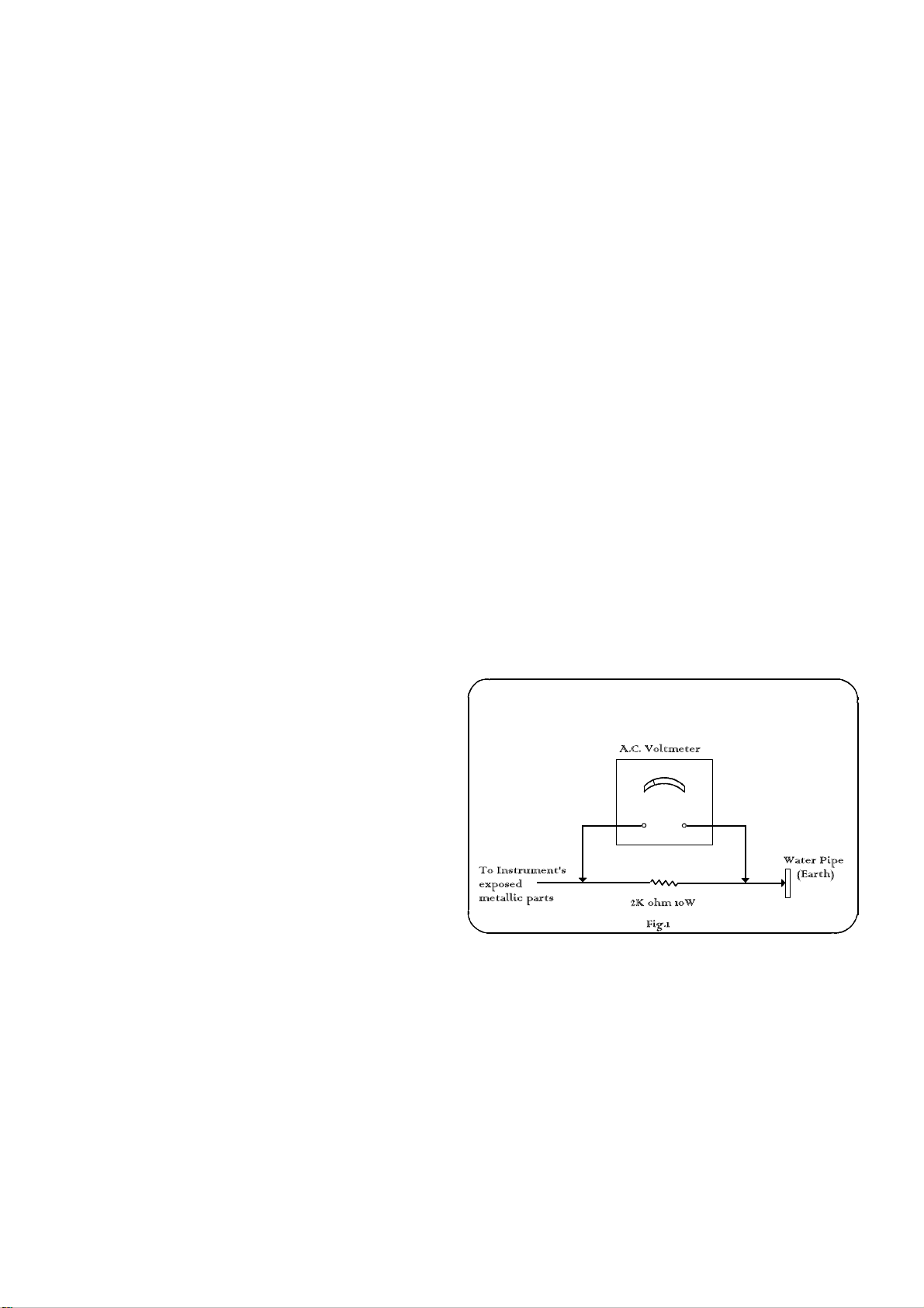
6. After servicing make the following leakage current checks to
prevent the customer from being exposed to shock hazards.
3. Use an AC voltmeter with high impedance to measure the
potential across the resistor.
4. Check each exposed Metallic part and check the voltage at
each point.
5. Reverse the AC plug at the outlet and repeat each of the
above measurements.
6. The potential at any point should not exceed 1.4 Vrms. In
case a measurement is outside the limits specified, there is a
possibility of a shock hazard, and the receiver should be
repaired and rechecked before it is returned to the customer.
HOT CHECK CIRCUIT
Leakage Current Cold Check
1. Unplug the AC cord and connect a jumper between the two
prongs of the plug.
2. Turn on the receiver's power switch.
3. Measure the resistance value with an ohmmeter, between
the jumpered AC plug and each exposed metallic cabinet
part on the receiver, such as screw heads, aerials ,
connectors, control shafts etc. When the exposed metallic
part has a return path to the chassis the reading should be
between 4M ohm and 20M ohm. When the exposed metal
does not have a return path to the chassis the reading must
be infinite.
Leakage Current Hot Check
1. Plug the AC cord directly into the AC outlet. Do not use an
isolation transformer for this check.
2. Connect a 2k ohm 10W resistor in series with an exposed
metallic part on the receiver and an earth such as a water
pipe.
X-Radiation Warning
1. The potential sources of X-Radiation in TV sets are the high
voltage section and the picture tube.
2. When using a picture tube test jig for service ensure that the
jig is capable of handling 32kV without causing X-Radiation.
NOTE : It is important to use an accurate periodically calibrated high
voltage meter
1. Set the brightness to minimum.
2. Measure the high voltage. The meter should indicate 31kV
_1kV at zero beam current if the meter indication is out of
tolerance, immediate service and correction is required to
prevent the possibility of premature component failure.
3. To prevent an X-Radiation possibility, it is essential to use
the specified tube.
Page 4
Location Of Controls
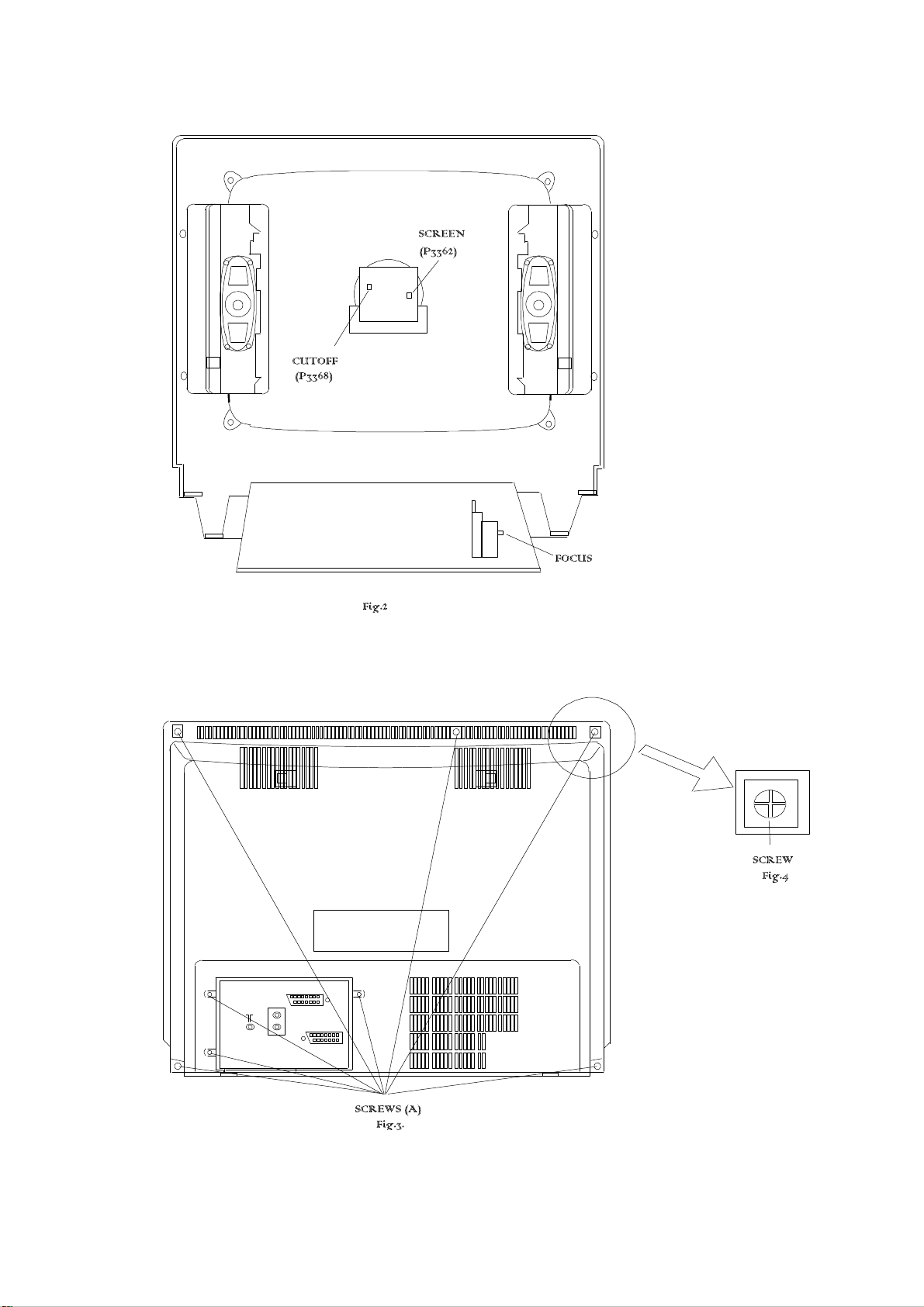
Service Hints
How to remove the rear cover
1. Remove the 8 fixing screws (A) as shown in Fig.3/Fig.4.
Page 5
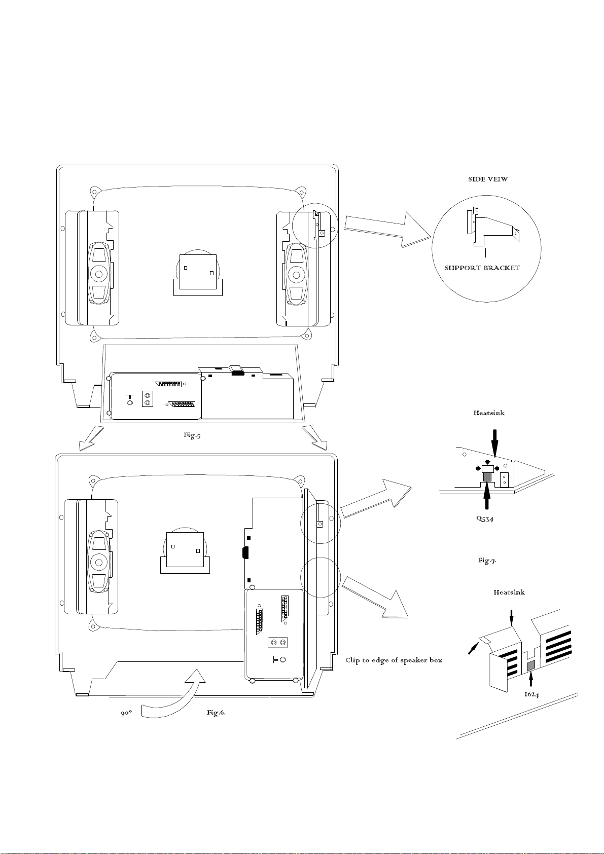
How to move the chassis into the Service position
1. Hold and lift the rear of the E- PCB chassis and M - PCB as shown in fig.5. and gently pull the chassis toward you. Realese the M PCB as explained on page 6
2. Turn the chassis through 90_, anti-clockwise, as shown in fig.6.
3. Clip the chassis onto the support bracket as shown in fig.6 and fig.7.
4. After servicing ensure all wiring is returned to its original position before returning the receiver to the customer.
Page 6
HOW TO REMOVE THE CONTROL PANEL (M-BOARD)
1. Remove the E-board from the cabinet with the M-board attached.
2. Unclip by lifting the front of the M-board vertically.
3. After servicing ensure all wiring is returned to its original position before returning the receiver to the customer.
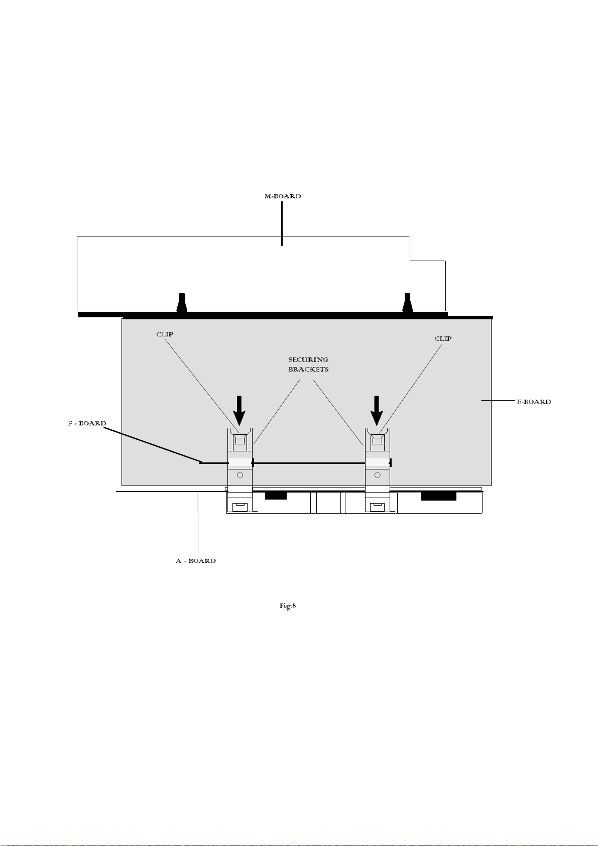
HOW TO REMOVE THE A - BOARD
1. Disconnect the 5 leads from the A - board.
2. Release the A and F boards securing brackets by pushing the clips in the direction shown in Fig.8, and remove the A - board by
gently lifting vertically.
3. After servicing ensure all wiring is returned to its original position before returning the receiver to the customer.
Page 7
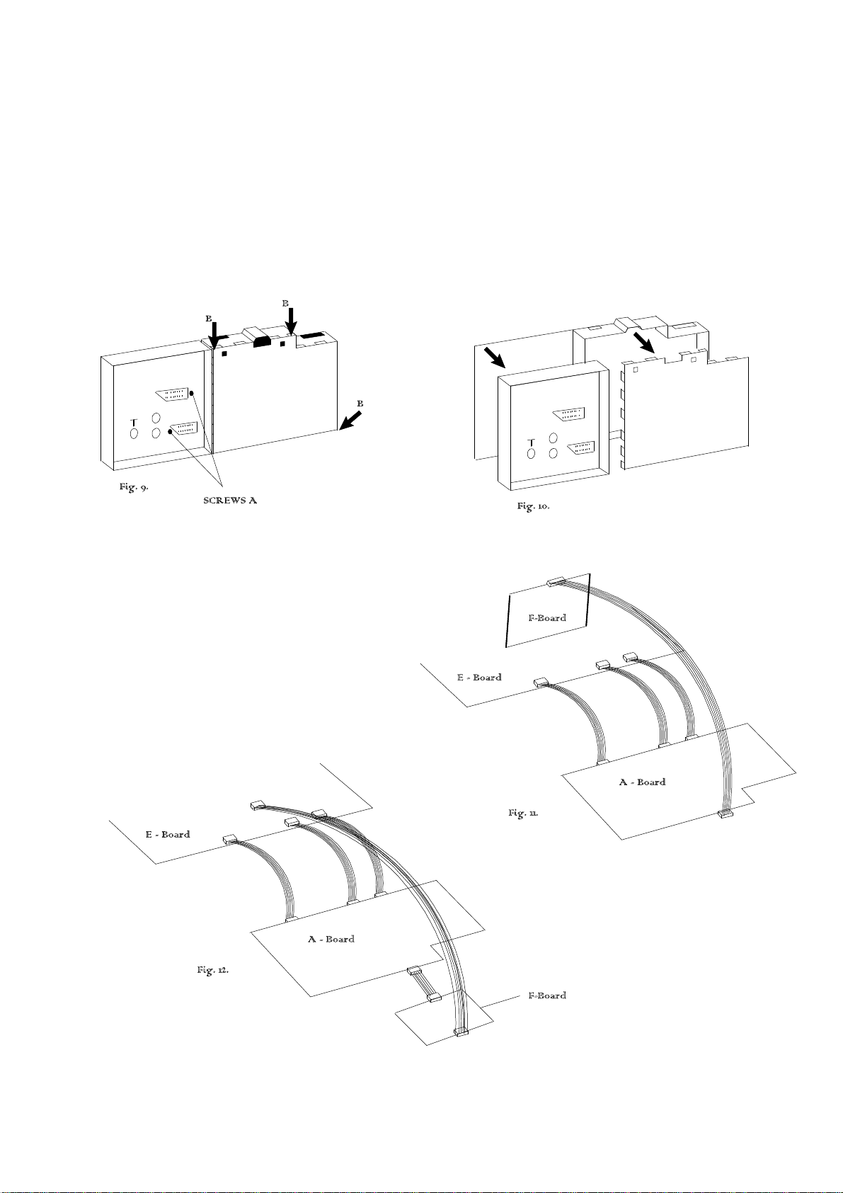
Service position for the A-Board
1. Remove the A-board from the main chassis (E-board) as shown in Fig.8.
2. Remove the two screws (A) (fig.9) from the plastic AV cover and unclip the AV cover from the A-board.
3. Carefully unclip the three metal clips marked B in fig.9.
4. Unclip the front metal cover (Fig10) and remove from the A-board.
5. Fit the extension leads to the A-board making sure that the A-board does not touch the E-board (fig.11).
6. After servicing ensure all wiring is returned to its original position before returning the receiver to the customer.
Note : The extension lead wire kit is supplied as a service kit. (Part number TZS4EP001).
Page 8
Service Mode
The remote control is used for entering and storing adjustments, with the exception of cut-off adjustments which must always be done prior to
service adjustment. Perform adjustments in accordance with screen display. The display on the screen also specifies the CCU variants as
well as the approx. setting values.The adjustment sequence for the service mode is indicated below.
1. Set the Bass to maximum position, set the Treble to minimum
position, press the F button followed by the Volume down on
the customer controls at the front of the TV and at the same
time press the Reveal button on the remote control, this will
place the TV into the Service Mode.
2. Press the RED / GREEN buttons to step down / up through
the functions.
NOTE: This TV also has the option of using a Memory Pack which enables you to copy the preset TV channels and analogue levels into the
Memory Pack and then upload them onto another EURO-2 TV set.
3. Press the YELLOW / BLUE buttons to alter the function
values.
4. Press the STORE button on the preset panel after each
adjustment has been made to store the required values.
5. To exit the Service Mode press the Normalisation button.
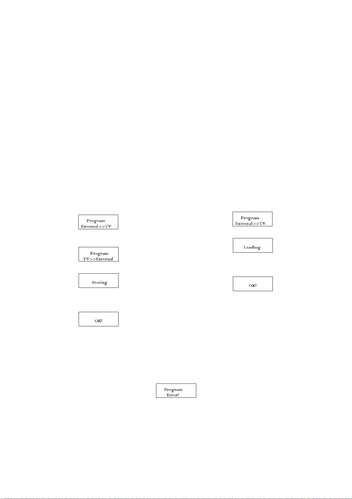
Using the Memory Pack
TV to Memory Pack process
1. Plug the memory pack into the lower of the two 21 pin
terminals at the back of the TV and switch the TV on. If the
TV has only one 21 pin connector then this will be able to
accept the memory pack.
2. Go into the Service Mode as explained above. The screen
will show:-
3. Press the blue button on the remote control. The screen will
show:-
Memory Pack to TV Process
1. Plug the memory pack into the lower of the two 21 pin
terminals at the back of the TV and switch the TV on. If the
TV has only one 21 pin connector then this will be able to
accept the memory pack.
2. Go into the Service Mode as explained above. The screen
will show:-
3. Press the STORE button on the TV. The screen will show:-
4. All the tuning information stored inside the Memory Pack will
4. Press the STORE button on the TV. The screen will show:-
5. All the tuning information stored inside the TV will now be
transferred to the Memory Pack. This process will take 2-3
minutes to complete and when finished the screen will show:-
now be transferred to the TV. This process will take 2-3
minutes to complete and when finished the screen will show:-
5. The tuning information from the Memory Pack has now been
copied into the TV
6. To exit from the Service Mode switch off the TV.
7. The process has now been completed and the Memory Pack
can now be removed.
Errors
If an error occurs while using the Memory Pack the TV will detect this and the screen will show:-
If this happens then switch off the TV and repeat the process that was being used. If the errors continue to occur then check the connectors
between the TV and the memory pack and check the 9V battery inside the memory pack.
Page 9
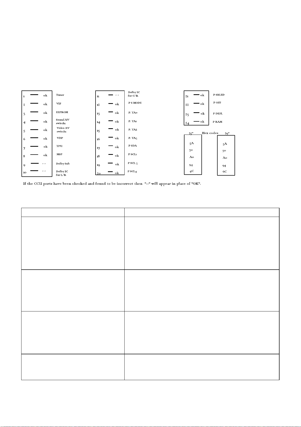
SELF CHECK
Self check is used to automatically check the Bus lines and Hexadecimal code of the TV set.
To enter the Self Check mode press Function down button, on the Preset Panel, at the same time pressing the Status button, on the Remote
Control, and the screen will show:-
Adjustment Procedure
Item/Preparation Adjustments
+B SET-UP
1. Operate the TV set
2. Set the controls:
Brightness minimum
Contrast minimum
RF AGC
1. Receive a test pattern.
2. Connect an oscilloscope between the
tuner RF AGC and ground.
3. Set the oscilloscope gain range to
1V/div.
CUT OFF
1. Receive a black and white signal.
2. Degauss the tube externally.
3. Set the TV into Service Mode 1.
4. Select Ug2 Test.
1. Set the +B voltage up as follows:
Adjust P633 so that U147 shows 147V +/- 0.5V
2. Confirm the following voltages.
U5 5 +/- 0.25V U28 28 +/- 1.0V
U8 8 +/- 0.5V U40 38.5+1.5/-1.0V
U12 12 +/- 0.5V U210 209 +/- 10V
U16 16.0 +/- 0.5/-1V U5SB 5.0 +/- 0.25V
U25 24.8 +/- 1.0V UM 8 +/- 0.5
1. Check that the noise becomes large when the RF AGC VR
P4701 is turned counterclockwise. After the check turn it
clockwise.
2. Gradually turn the RF AGC VR anti-clockwise, and set the
RF AGC VR to the point where the RF AGC voltage is just falling to a
point where this voltage drops by 0.2V from the maximum value.
1. Confirm which colour has the biggest value
2. Turn the screen VR P3368 to minimum.
3. Connect an oscilloscope to the cathode with the biggest value colour.
4. Adjust P3368 to get a low light pulse voltage of 180V +/- 5V.
5. Adjust P3362 to whichever colour reaches 50 +/- 10 first.
COMB FILTER
1. Receive A PAL colour bar signal. 1. Confirm input video signal (pin 4 W2601 is 1Vp-p).
2. Adjust P2601 to obtain 2Vp-p at TPF1.
Page 10

Alignment Settings
Alignment Function TX-29AD1E TX-25AD1E Settings / Special features
1. Vertical amplitude V-AMP
051
2. Vertical symmetry V-SYM
013
3. Vertical linearity V-LIN
012
4. Vert. D.C. Vert. D.C.
000
5. V-Pos. V. Pos
003
6. Horizontal amplitude H-AMP
-033
7. Horizontal position H-POS
049
8. Text Position TEXT POSITION
045
9. EW-amplitude E-W AMP1
-058
10. EW-amplitude E-W AMP2
023
11. Trapezium-comp TRAPEZ-1
-014
12. Trapezium- comp TRAPEZ-2
012
13. Colour VCO COLOUR VCO
015
14. Cut-off DC CUT-OFF DC
050
15. Ug2 Test Ug2 Test
107 021 023
16. Cutoff Cutoff
045 055 050
17. White White
224 255 237
V-AMP
063
V-SYM
002
V-LIN
-020
Vert. D.C.
000
V. Pos
005
H-AMP
-044
H-POS
069
TEXT POSITION
049
E-W AMP1
-058
E-W AMP2
044
TRAPEZ-1
-000
TRAPEZ-2
-009
COLOUR VCO
006
CUT-OFF DC
050
Ug2 Test
94 044 020
Cutoff
057 064 056
White
200 255 248
Optimum setting
Optimum setting
Optimum setting
Optimum setting
Optimum setting
Optimum setting
Optimum setting
Optimum setting
Optimum setting
Optimum setting
Optimum setting
Optimum setting
Optimum setting
Not to be adjusted.
To adjust the screen settings.
Turn P3362 until a colour
reaches 25"5, place an
oscilloscope probe on the
cathode with the highest output
and adjust P3368 so the
oscilloscope trace reads
150V 0-peak (160V 0-peak TX 25AD1E), then turn P3362 up so
the highest numbered box on the
TV screen reads 050 " 010.
Press the GREEN button to step
through the settings.
Adjust for optimum.
Press the GREEN button to step
through the settings.
Adjust for optimum.
Page 11
PCB
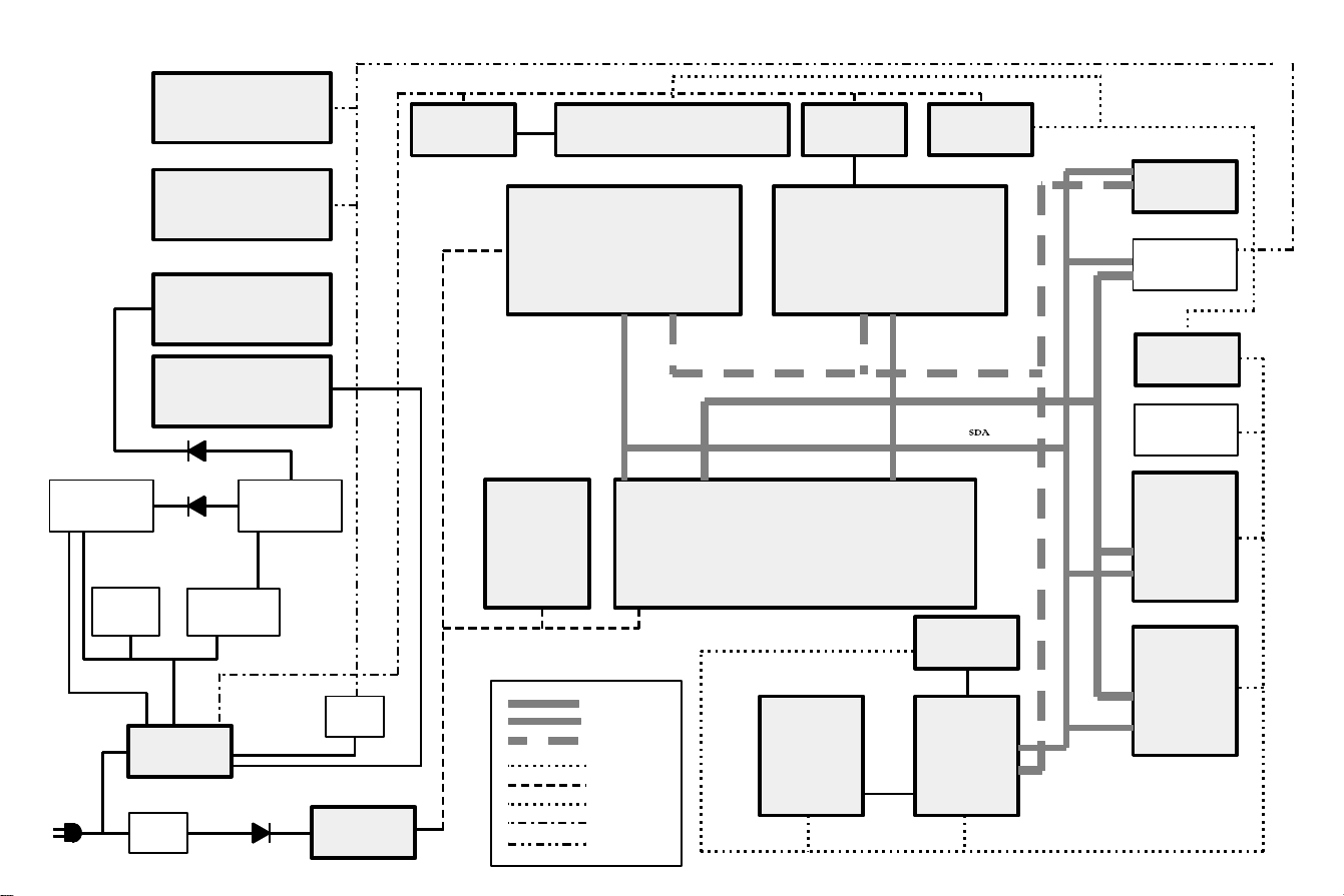
POWER SUPPLY AND CONTROL BLOCK DIAGRAM
I2651
COMB FILTER
CONTROL
I2601
COMB FILTER
I561
VERTICAL OUTPUT
I466
AUDIO OUTPUT
27V
D557
Y
200V
FBT
D547
I4071
12V REG
I1871
EPROM
PROGRAMME
MEMORY
SOUND PROCESSOR
IF PROCESSOR
I1301
I4700
MICROPROCESSOR
CONTROL
I1801
I1351
8V REG
I1601
VIDEO PROCESSOR
I661
12V REG
12V
I1941
EEPROM
MEMORY
TUNER
I646
9V REG
HEADPHONE
AMP
I1011
AV
SWITCHING
9V
Q526
DRIVER
150V
PSU
CONTROL
T6101
I611
Q543
LINE
OUTPUT
2
4
V
15V
D6101
20V
5V
Q674
I1601
5V REG
5VSB
CLOCK 4
DATA
CLOCK 1
12V
5VSB
9V
15V
5V
15V
9V
I1751
TEXT
MEMORY
I1981
RESET
I1701
TELETEXT
I1111
AV
SWITCHING
Page 12
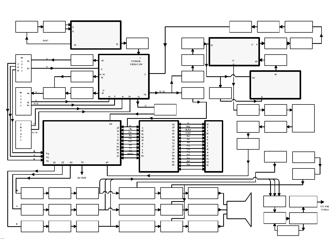
VIDEO BLOCK DIAGRAM
AV1
AV2
AV3
TUNER
X4704
FILTER
Q1172
MIXER
VIDEO DEMODULATOR
Q1123
BUFFER
Q1167
BUFFER
Q1163
BUFFER
I1601
VIDEO PROCESSOR
I4700
I1111
AV SWITCH
Q4701
BUFFER
Q1182
BUFFER
I1701
TELETEXT
Q2613
BUFFER
Q2614
AMP
Q1267
BUFFER
Q1192
BUFFER
Q2651
BUFFER
I
1
7
5
1
M
E
M
O
R
Y
Q2602
BUFFER
I2601
COMB FILTER
Q2611
BUFFER
FILTER
Q2601
BUFFER
Q2604
BUFFER
SPOT SU
Q2612
BUFFER
Q2653
BUFFER
I2651
Q2609
BUFFER
Q2603
DRIVER
Q3368
PRESS
Q2608 Q2606
AMP
Q2610
BUFFER
Q2607
Q2605
AMP
Q3359
CUTOFF
Q3368
SPOT SU
PRESS
Q1651
AMP
Q1641
AMP
Q1631
AMP
Q1653
BUFFER
Q1643
BUFFER
Q1633
BUFFER
Q1656
AMP
Q1646
AMP
Q1636
AMP
Q3162 Q3164 Q3166
Q3169 Q3391
Q3172 Q3174 Q3176
Q3179 Q3381
Q3182 Q3184 Q3186
Q3189 Q3371
Q3393
DRIVE
Q3383
DRIVE
Q3373
DRIVE
Q3394 Q3397
OUTPUT AMP
Q3384 Q3387
OUTPUT AMP
Q3374 Q3377
OUTPUT AMP
RESISTOR
MATRIX
Q3109 Q3108
Q3111 Q3122
Q3143
AMP
Q3131 Q3136
OUTPUT AMP
Q3126 Q3127
DRIVER
Page 13
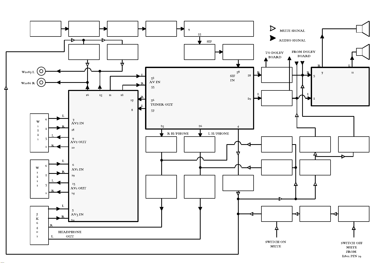
AUDIO BLOCK DIAGRAM
TUNER
AV2
X4704
FILTER
Q1091
MUTE
AV SWITCHING
I1011
Q4704
BUFFER
Q1071
MUTE
Q4704
AMP
Q1466
BUFFER
SIF FILTER
Q4702
AMP
I1301
AUDIO
MIXER
DEMODULATOR
VOLUME
BASS
TREBLE
CONTROL
Q1476
BUFFER
I4700
Q4703
BUFFER
Q1486
BUFFER
Q1496
BUFFER
Q6403
MUTE
Q6433
MUTE
AUDIO OUTPUT
Q498
MUTE
Q497
MUTE
I466
AMP
Q496
MUTE
AV1
AV3
Q6413
Q6417
AMP
Q6443
Q6447
AMP
Q1382
MUTE
Q463
MUTE
Q494
MUTE
Q1812
BUFFER
Page 14
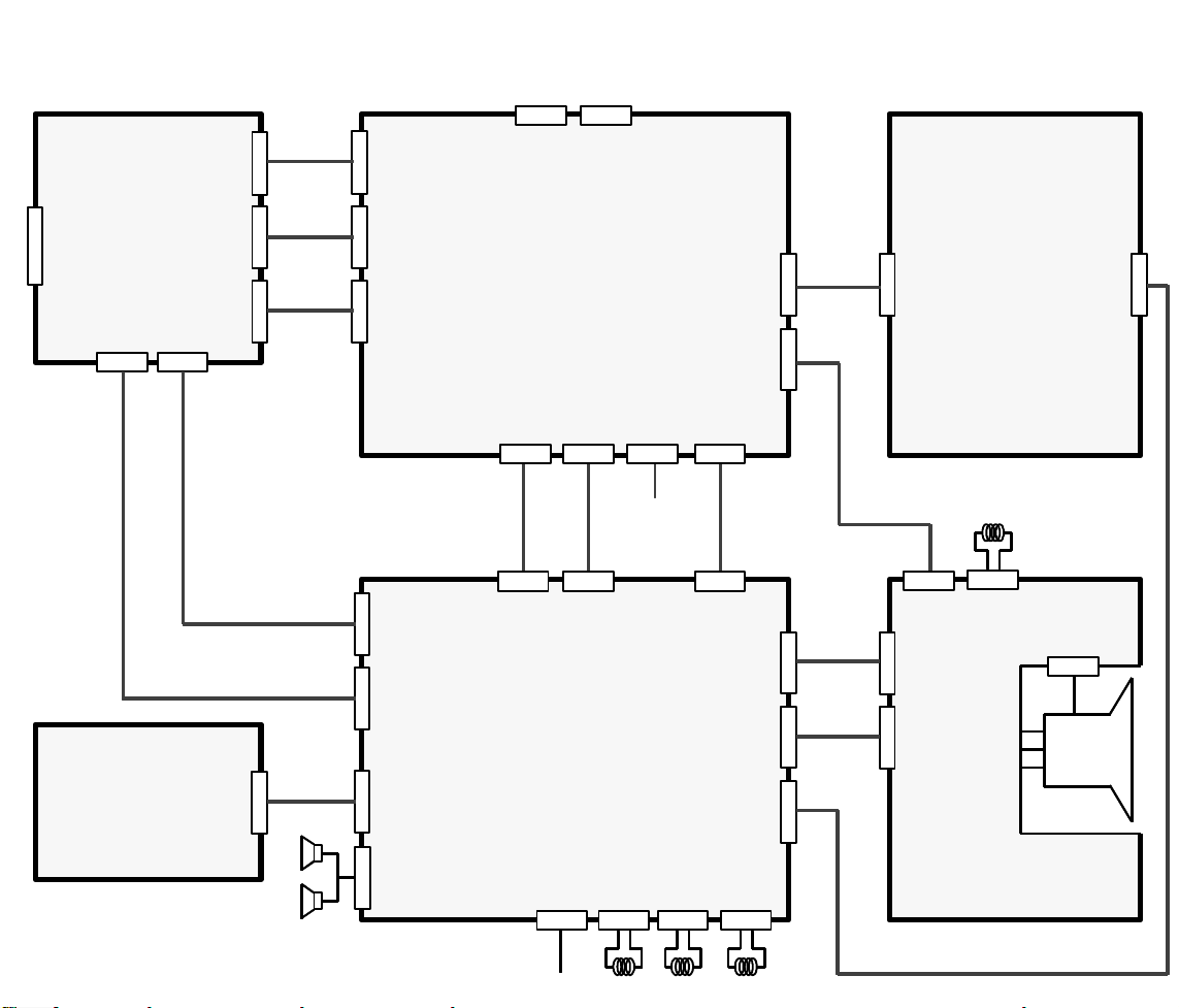
WIRING BLOCK DIAGRAM
MAFEB
Y
W
1
2
41W
127
1
W
1
933
W
6
301W640
2
W
6
4
01J
K
6
4
01W
1
2
5
1W2
6
0
1W1
6
5
1W612
W
214
W
252
W4001
W63
0
W
6
60W54
8
W
3
317
W
3
1
52W
260
2
W3316
W6102
W6010
W1370
W610
W1951
W1511
W511
W1201
W211
AV3
W1221
W1211
AV1
AV2W7
4
0
W534
W569
W619
DEGAUSS
V DY
H DY
W534VMCOIL
W3316
W554
TO CRT
SCREEN
FACTORY
ADJUSTMENT
Page 15

WAVEFORM PATTERN TABLE
Page 16

SCHEMATIC DIAGRAM FOR MODELS
TX-29/25AD1E
(EURO-2S CHASSIS)
Notes
1. RESISTOR
All resistors are carbon ¼W resistor, unless marked.
Unit of resistance is OHM (W) (K=1,000, M=1,000,000).
2. CAPACITOR
All capacitors are ceramic 50V capacitors, unless marked, the unit of capacitance is mF unless otherwise stated.
3. COIL
Unit of inductance is mH, unless otherwise stated.
4. TEST POINT
:Test Point Position
3
:Waveform Test Point Position
5. EARTH SYMBOL
Chassis Earth (Cold)
Line Earth (Hot)
6. VOLTAGE MEASUREMENT
Voltage is measured by a DC voltmeter.
Measurement conditions are as follows:
Power source AC 220-240V, 50Hz
Receiving Signal Colour Bar signal (RF)
All customer controls Maximum position
7.
: Indicates the Video signal path
: Indicates the Audio signal path
: Indicates the Vertical/Horizontal signal path
8. This schematic diagram is the latest at the time of printing and is subject to change without notice.
Precautions
a. Do not touch the hot part, or the hot and cold parts at the same time, as you are liable to a shock hazard.
b. Do not short-circuit the hot and cold circuits as electrical components may be damaged.
c. Do not connect an instrument, such as an oscilloscope, to the hot and cold circuits simultaneously, as this may cause fuse failure.
Connect the earth of the instruments to the earth connection of the circuit being measured.
d. Make sure to disconnect the power plug before removing the chassis.
Remarks
1. The Power Circuit contains a circuit area which uses a separate power supply to isolate the earth connection. The circuit is defined by
HOT and COLD indications in the schematic diagram. All circuits, except the Power Circuit, are COLD.
Page 17

PARTS LOCATION
NOTE :
2
1
4
3
5
7
6
13
17
18
15
10
22
9
11
20
21
12
8
16
14
19
Page 18

REPLACEMENT PARTS LIST
Important Safety Notice
PARTS COMMON TO TX-29AD1E AND TX-25AD1E
MISCELLANEOUS COMPONENTS
1) EUR51920 REMOTE CONTROL
2) ********** SEE DIFFERENCE LIST
3) ********** SEE DIFFERENCE LIST
4) ********** SEE DIFFERENCE LIST
5) THT1009R CRT FIXING SCREW
6) ********** SEE DIFFERENCE LIST
7) ********** SEE DIFFERENCE LIST
8) TNP117038AA M P.C.B.
9) ********** SEE DIFFERENCE LIST
10) ********** SEE DIFFERENCE LIST
11) ENV578F5G3 TUNER
12) TNP117039AC B P.C.B.
13) TMX8E005 CHASSIS FRAME
14) TMW8E016 CONTROL BRACKET
15) TKP8E1109 A.V. DOOR
16) ********** SEE DIFFERENCE LIST
17) ********** SEE DIFFERENCE LIST
18) TSX8E0011 MAINS LEAD
19) TKP8E1109 A.V. DOOR
20) TBX8E021 POWER BUTTON
21) TBM153022 PANASONIC BADGE
22) TNP117035 F P.C.B.
TQB8E0917A INST BOOK GERMAN
TQB8E0917B INST BOOK DUTCH
TQB8E0917D INST BOOK FRENCH
TQB8E0917E INST BOOK SPANISH
TQB8E0917F INST BOOK SWEDISH
TQB8E0917G INST BOOK NORWEGIAN
TQB8E0917H INST BOOK SUOMI
TQB8E0917J INST BOOK PORTUGUESE
TQB8E0917K INST BOOK DANISH
TBM8E1182 ANTENNA BLIND SHEET
TBX8E022 OPERATE KEY
TEK6343 LID DAMPER
TBM8E1359 INDICATION SHEET
TBM8E1360 INDICATION SHEET
TBM8E1475 BLIND SHEET
TEK6940 LID CATCHER
TES2249 SPRING FOR POWER BUTTON
TES2298 CRT EARTH SPRING
TMW8E017 L.E.D. HOLDER
TNA10804 VIF PACK
TPD8E562 CUSHION
UM-3DEP-2P BATTERY
CAPACITORS
C202 ECQB1H103J FILM 50V 10nF
C203 ECEA1CU221 ELECT 16V 220mF
C204 ECQB1H104J FILM 50V 100nF
C206 222236516334 FILM 160V 330nF
C209 ECQB1H104J FILM 50V 100nF
C212 ECEA1HUR22 ELECT 50V 0.22mF
C226 ECQB1H104J FILM 50V 100nF
C228 ECKC1H102J CERAMIC 50V 1000pF
C229 ECKC1H102J CERAMIC 50V 1000pF
C462 ECEA1EU101 ELECT 25V 100mF
C463 ECEA1EU471 ELECT 25V 470mF
C465 ECEA1CU470 ELECT 16V 47mF
C466 ECEA1HU222 ELECT 50V 2200mF
C467 ECQB1H103J FILM 50V 10nF
C471 ECEA1HU010 ELECT 50V 1mF
C472 ECEA1CU101 ELECT 16V 100mF
C473 ECEA1EGE222 ELECT 25V 2200mF
C476 ECEA1HU4R7 ELECT 50V 4.7mF
C479 222236576104 FILM 760V 100nF
C481 ECEA1HU010 ELECT 50V 1mF
C482 ECEA1CU101 ELECT 16V 100mF
C483 ECEA1EGE222 ELECT 25V 2200mF
C486 ECEA1HU4R7 ELECT 50V 4.7mF
C489 222236576104 FILM 760V 100nF
C492 ECEA1VU4R7 ELECT 35V 4.7mF
C495 ECEA1EU101 ELECT 25V 100mF
C496 ECEA1CU100 ELECT 16V 10mF
C521 ECEA1HU101 ELECT 50V 100mF
C524 222236516105 FILM 160V 1mF
C527 ECQM2683JZ FILM 250V 68nF
C531 ECQM2564KZ FILM 250V 560nF
C536 ECWH12H103J FILM 1250V 10nF
C538 ECWF2H514J FILM 500V 510nF
C543 ECEA2VU2R2 ELECT 350V 2.2mF
C544 ECKC3D152J CERAMIC 2KV 1.5nF
C547 ECKC2H101J CERAMIC 500V 100pF
C548 ECEA2EU220 ELECT 250V 22mF
C549 ECEA2AU2R2 ELECT 100V 2.2mF
C557 ECKC2H101J CERAMIC 500V 100pF
C558 ECEA1VU102 ELECT 35V 1000mF
C561 ECEA1VU222 ELECT 35V 2200mF
C562 222236576104 FILM 760V 100nF
C564 ECQB1H473K FILM 50V 47nF
C568 222236516224 FILM 160V 220nF
C574 ECEA1VU332 ELECT 35V 3300mF
C577 222236516105 FILM 160V 1mF
C579 ECKC1H472J CERAMIC 50V 4.7nF
C592 ECEA1CU330 ELECT 16V 33mF
C594 ECKC1H103JB CERAMIC 50V 10nF
C595 ECQB1H102J FILM 50V 1nF
C618 ECOS2GG181NG ELECT 400V 180mF
C619 ECQE6104K FILM 600V 100nF
C622 ECEA1HFS470 ELECT 50V 47mF
C623 222236516224 FILM 160V 220nF
C626 ECKC3D471JB CERAMIC 2KV 470pF
C628 ECKC1H221J CERAMIC 50V 220pF
C629 ECQB1H153K FILM 50V 15nF
C631 ECQB1H472J FILM 50V 4.7nF
C632 ECQB1H103J FILM 50V 10nF
C634 ECEA1HGE010 ELECT 50V 1mF
C635 ECKC3D331J CERAMIC 2KV 330pF
C636 ECKC2H472J CERAMIC 500V 4.7nF
C637 ECQB1H222J FILM 50V 2200pF
C638 ECQF6333JZH FILM 600V 33nF
C639 ECKCWS222MEJ CERAMIC 2200pF
Page 19

C647 222236516334 FILM 160V 330nF
C650 ECKC3A102J CERAMIC 1KV 1nF
C651 ECOS2EA221AB ELECT 400V 220mF
C656 ECKC2H681J CERAMIC 500V 680pF
C657 ECEA1HU471 ELECT 50V 470mF
C661 ECKC2H821J CERAMIC 500V 820pF
C662 ECEA1EU222 ELECT 25V 2200mF
C666 222236516224 FILM 160V 220nF
C667 ECEA1CU471 ELECT 16V 470mF
C671 ECKC2H681J CERAMIC 500V 680pF
C672 ECEA1EU222 ELECT 25V 2200mF
C677 ECEA1CU471 ELECT 16V 470mF
C681 ECEA1EGE101 ELECT 25V 100 mF
C682 ECKC2H331J CERAMIC 500V 330pF
C687 ECEA1HGE102 ELECT 50V 1000mF
C1001 ECEA1CU470 ELECT 16V 47mF
C1002 ECUV1H104ZFX S.M. CAP 50V 100nF
C1011 ECEA1CU470 ELECT 16V 47mF
C1012 ECUV1H473ZFX S.M. CAP 50V 47nF
C1013 ECEA1CU470 ELECT 16V 47mF
C1019 ECEA1CU470 ELECT 16V 47mF
C1020 ECEA1CU470 ELECT 16V 47mF
C1021 ECEA1HUR47 ELECT 50V 0.47mF
C1022 ECEA1HUR47 ELECT 50V 0.47mF
C1023 ECUV1H221JCX S.M. CAP 50V 220pF
C1024 ECUV1H221JCX S.M. CAP 50V 220pF
C1031 ECEA1HNR47 ELECT 50V 0.47mF
C1032 ECEA1HUR47 ELECT 50V 0.47mF
C1033 ECUV1H221JCX S.M. CAP 50V 220pF
C1034 ECUV1H221JCX S.M. CAP 50V 220pF
C1036 ECEA1CU470 ELECT 16V 47mF
C1038 ECEA1CU470 ELECT 16V 47mF
C1041 ECUV1H103KBX S.M. CAP 50V 10nF
C1042 ECUV1H103KBX S.M. CAP 50V 10nF
C1043 ECEA1HUR47 ELECT 50V 0.47mF
C1044 ECEA1HUR47 ELECT 50V 0.47mF
C1051 ECEA1HNR33 ELECT 50V 0.33mF
C1052 ECEA1HNR33 ELECT 50V 0.33mF
C1071 ECEA1CN470 ELECT 16V 47mF
C1091 ECEA1CU470 ELECT 16V 47mF
C1101 ECEA1HUR47 ELECT 50V 0.47mF
C1111 ECEA1HU470 ELECT 50V 47mF
C1112 ECUV1H473ZFX S.M. CAP 50V 47nF
C1116 ECUV1H473ZFX S.M. CAP 50V 47nF
C1121 ECEA1HUR47 ELECT 50V 0.47mF
C1124 ECUV1H473ZFX S.M. CAP 50V 47nF
C1126 ECEA1CU470 ELECT 16V 47mF
C1151 ECUV1H102KBX S.M. CAP 50V 1nF
C1158 ECEA1HUR47 ELECT 50V 0.47mF
C1161 ECUV1H102KBX S.M. CAP 50V 1nF
C1178 ECUV1H473ZFX S.M. CAP 50V 47nF
C1179 ECEA1CU470 ELECT 16V 47mF
C1183 ECUV1H104ZFX S.M. CAP 50V 100nF
C1193 ECUV1H104ZFX S.M. CAP 50V 100nF
C1226 ECUV1H560JCX S.M. CAP 50V 56pF
C1231 ECUV1H104ZFX S.M. CAP 50V 100nF
C1241 ECUV1H472KBX S.M. CAP 50V 4.7nF
C1242 ECUV1H472KBX S.M. CAP 50V 4.7nF
C1263 ECUV1H102KBX S.M. CAP 50V 1nF
C1266 ECUV1H104ZFX S.M. CAP 50V 100nF
C1271 ECUV1H102KBX S.M. CAP 50V 1nF
C1273 ECEA1HUR47 ELECT 50V 0.47mF
C1282 ECEA1HUR47 ELECT 50V 0.47mF
C1284 ECEA1HUR47 ELECT 50V 0.47mF
C1301 ECEA1CU100 ELECT 16V 10mF
C1302 ECUV1H104ZFX S.M. CAP 50V 100nF
C1303 ECEA1CU100 ELECT 16V 10mF
C1304 ECUV1H104ZFX S.M. CAP 50V 100nF
C1306 ECEA1CU101 ELECT 16V 100mF
C1307 ECUV1H104ZFX S.M. CAP 50V 100nF
C1309 ECEA1CU100 ELECT 16V 10mF
C1310 ECEA1CU100 ELECT 16V 10mF
C1311 ECUV1H104ZFX S.M. CAP 50V 100nF
C1312 ECEA50Y3R3 ELECT 50V 3.3mF
C1313 ECUV1H471JCX S.M. CAP 50V 470pF
C1314 ECUV1H471JCX S.M. CAP 50V 470pF
C1315 ECEA1CU100 ELECT 16V 10mF
C1316 ECUV1H104ZFX S.M. CAP 50V 100nF
C1321 ECUV1H030CCX S.M. CAP 50V 30pF
C1322 ECUV1H030CCX S.M. CAP 50V 30pF
C1326 ECQM1H334J FILM 50V 330nF
C1327 ECUV1H221JCX S.M. CAP 50V 220pF
C1331 ECUV1H391JCX S.M. CAP 50V 390pF
C1332 ECUV1H391JCX S.M. CAP 50V 390pF
C1346 ECUV1H221JCX S.M. CAP 50V 220pF
C1347 ECUV1H221JCX S.M. CAP 50V 220pF
C1351 ECEA1CU470 ELECT 16V 47mF
C1352 ECUV1H104ZFX S.M. CAP 50V 100nF
C1353 ECUV1H104ZFX S.M. CAP 50V 100nF
C1377 ECUV1H104ZFX S.M. CAP 50V 100nF
C1382 ECUV1H104ZFX S.M. CAP 50V 100nF
C1409 ECUV1H470JCX S.M. CAP 50V 47pF
C1411 ECUV1H070DCX S.M. CAP 50V 7pF
C1412 ECUV1H100DCX S.M. CAP 50V 10pF
C1413 ECUV1H220JCX S.M. CAP 50V 22pF
C1416 ECUV1H070DCX S.M. CAP 50V 7pF
C1417 ECUV1H560JCX S.M. CAP 50V 56pF
C1444 ECUV1H102KBX S.M. CAP 50V 1nF
C1454 ECUV1H102KBX S.M. CAP 50V 1nF
C1463 ECUV1H102KBX S.M. CAP 50V 1nF
C1465 ECUV1H560JCX S.M. CAP 50V 56pF
C1467 ECUV1H102KBX S.M. CAP 50V 1nF
C1468 ECUV1H102KBX S.M. CAP 50V 1nF
C1473 ECUV1H102KBX S.M. CAP 50V 1nF
C1475 ECUV1H560JCX S.M. CAP 50V 56pF
C1483 ECUV1H102KBX S.M. CAP 50V 1nF
C1487 ECUV1H103KBX S.M. CAP 50V 10nF
C1493 ECUV1H102KBX S.M. CAP 50V 1nF
C1497 ECUV1H103KBX S.M. CAP 50V 10nF
C1601 ECEA1CU470 ELECT 16V 47mF
C1602 ECUV1H103KBX S.M. CAP 50V 10nF
C1606 ECEA0JU102 ELECT 6.3V 1000 mF
C1607 ECUV1H103KBX S.M. CAP 50V 10nF
C1611 ECEA1CU470 ELECT 16V 47mF
C1612 ECUV1H103KBX S.M. CAP 50V 10nF
C1613 ECEA1CU100 ELECT 16V 10mF
C1614 ECUV1H473ZFX S.M. CAP 50V 47nF
C1615 ECUV1H103KBX S.M. CAP 50V 10nF
C1616 ECUV1H101JCX S.M. CAP 50V 100pF
C1617 ECUV1H470JCX S.M. CAP 50V 47pF
C1618 ECUV1H470JCX S.M. CAP 50V 47pF
C1619 ECUV1H103KBX S.M. CAP 50V 10nF
C1620 ECUV1H102KBX S.M. CAP 50V 1nF
C1621 ECUV1H103KBX S.M. CAP 50V 10nF
C1622 ECEA1CU100 ELECT 16V 10mF
C1624 ECEA1HNR22 ELECT 50V 0.22mF
C1625 ECUV1H101JCX S.M. CAP 50V 100pF
C1626 ECUV1H104ZFX S.M. CAP 50V 100nF
C1627 ECEA1HNR22 ELECT 50V 0.22mF
C1641 ECUV1H104ZFX S.M. CAP 50V 100nF
C1651 ECUV1H104ZFX S.M. CAP 50V 100nF
C1652 ECUV1H104ZFX S.M. CAP 50V 100nF
C1653 ECUV1H104ZFX S.M. CAP 50V 100nF
C1655 ECEA1CU470 ELECT 16V 47mF
C1661 ECUV1H102KBX S.M. CAP 50V 1nF
C1662 ECUV1H683ZFX S.M. CAP 50V 68nF
C1663 ECUV1H102KBX S.M. CAP 50V 1nF
C1666 ECUV1H102KBX S.M. CAP 50V 1nF
C1667 ECUV1H683ZFX S.M. CAP 50V 68nF
C1668 ECUV1H104ZFX S.M. CAP 50V 100nF
C1672 ECEA1CU100 ELECT 16V 10mF
C1673 ECUV1H104ZFX S.M. CAP 50V 100nF
Page 20

C1680 ECUV1H471JCX S.M. CAP 50V 470pF
C1681 ECUV1H102KBX S.M. CAP 50V 1nF
C1682 ECUV1H102KBX S.M. CAP 50V 1nF
C1683 ECUV1H271JCX S.M. CAP 50V 270pF
C1684 ECUV1H121JCX S.M. CAP 50V 120pF
C1685 ECUV1H102KBX S.M. CAP 50V 1nF
C1686 ECUV1H271JCX S.M. CAP 50V 270pF
C1687 ECUV1H121JCX S.M. CAP 50V 120pF
C1688 ECUV1H471JCX S.M. CAP 50V 470pF
C1691 ECUV1H104ZFX S.M. CAP 50V 100nF
C1692 ECUV1H104ZFX S.M. CAP 50V 100nF
C1693 ECUV1H104ZFX S.M. CAP 50V 100nF
C1696 ECUV1H102KBX S.M. CAP 50V 1nF
C1697 ECUV1H100DCX S.M. CAP 50V 10pF
C1698 ECUV1H102KBX S.M. CAP 50V 1nF
C1699 ECUV1H100DCX S.M. CAP 50V 10pF
C1701 ECEA1CU470 ELECT 16V 47mF
C1702 ECUV1H103KBX S.M. CAP 50V 10nF
C1704 ECEA1CU470 ELECT 16V 47mF
C1706 ECUV1H104ZFX S.M. CAP 50V 100nF
C1714 ECUV1H103KBX S.M. CAP 50V 10nF
C1717 ECUV1H102KBX S.M. CAP 50V 1nF
C1721 ECUV1H473ZFX S.M. CAP 50V 47nF
C1722 ECUV1H102KBX S.M. CAP 50V 1nF
C1752 ECUV1H103KBX S.M. CAP 50V 10nF
C1753 ECEA1CU100 ELECT 16V 10mF
C1801 ECUV1H103KBX S.M. CAP 50V 10nF
C1802 ECEA1CU470 ELECT 16V 47mF
C1804 ECUV1H103KBX S.M. CAP 50V 10nF
C1811 ECUV1H332KBX S.M. CAP 50V 3.3nF
C1816 ERJ6GEYJ153 S.M.CARB 0.1W 5% 15KW
C1826 ERJ6GEYJ153 S.M.CARB 0.1W 5% 15KW
C1836 ECUV1H104ZFX S.M. CAP 50V 100nF
C1838 ECUV1H101JCX S.M. CAP 50V 100pF
C1843 ECUV1H472KBX S.M. CAP 50V 4.7nF
C1845 ECUV1H560JCX S.M. CAP 50V 56pF
C1849 ECEA1HU4R7 ELECT 50V 4.7mF
C1851 ECUV1H470JCX S.M. CAP 50V 47pF
C1852 ECUV1H390JCX S.M. CAP 50V 39pF
C1853 ECUV1H390JCX S.M. CAP 50V 39pF
C1857 ECUV1H560JCX S.M. CAP 50V 56pF
C1859 ECUV1H560JCX S.M. CAP 50V 56pF
C1871 ECUV1H103KBX S.M. CAP 50V 10nF
C1879 ECUV1H560JCX S.M. CAP 50V 56pF
C1888 ECUV1H103KBX S.M. CAP 50V 10nF
C1891 ECUV1H102KBX S.M. CAP 50V 1nF
C1893 ECUV1H102KBX S.M. CAP 50V 1nF
C1894 ECUV1H102KBX S.M. CAP 50V 1nF
C1922 ECUV1H103KBX S.M. CAP 50V 10nF
C1925 ECUV1H103KBX S.M. CAP 50V 10nF
C1931 ECUV1H103KBX S.M. CAP 50V 10nF
C1941 ECUV1H103KBX S.M. CAP 50V 10nF
C1942 ECEA1CU470 ELECT 16V 47mF
C1961 ECUV1H332KBX S.M. CAP 50V 3.3nF
C1962 ECUV1H332KBX S.M. CAP 50V 3.3nF
C1963 ECUV1H332KBX S.M. CAP 50V 3.3nF
C1964 ECUV1H332KBX S.M. CAP 50V 3.3nF
C1971 ECUV1H104ZFX S.M. CAP 50V 100nF
C1972 ECEA1CU470 ELECT 16V 47mF
C1973 ECUV1H104ZFX S.M. CAP 50V 100nF
C1974 ECUV1H104ZFX S.M. CAP 50V 100nF
C1976 ECUV1H104ZFX S.M. CAP 50V 100nF
C1977 ECEA1CU470 ELECT 16V 47mF
C1981 ECUV1H104ZFX S.M. CAP 50V 100nF
C1982 ECUV1H101JCX S.M. CAP 50V 100pF
C2603 ECUV1H100DCX S.M. CAP 50V 10pF
C2604 ECUV1H104ZFX S.M. CAP 50V 100nF
C2605 ECEA1CKA470 ELECT 16V 47mF
C2606 ECUV1H104ZFX S.M. CAP 50V 100nF
C2607 ECUV1H104ZFX S.M. CAP 50V 100nF
C2609 ECEA1CKA470 ELECT 16V 47mF
C2611 ECUV1H104ZFX S.M. CAP 50V 100nF
C2612 ECEA1CKA470 ELECT 16V 47mF
C2613 ECUV1H104ZFX S.M. CAP 50V 100nF
C2614 ECUV1H103ZFX S.M. CAP 50V 10nF
C2615 ECUV1H103ZFX S.M. CAP 50V 10nF
C2616 ECEA1CKA470 ELECT 16V 47mF
C2617 ECEA1HKNR47 ELECT 50V 0.47mF
C2618 ECEA1CKA470 ELECT 16V 47mF
C2619 ECUV1H104ZFX S.M. CAP 50V 100nF
C2620 ECEA1CKA100 ELECT 16V 10mF
C2621 ECQM1H474J FILM 50V 470nF
C2623 ECUV1H103ZFX S.M. CAP 50V 10nF
C2625 ECUV1H103ZFX S.M. CAP 50V 10nF
C2627 ECEA1CKA470 ELECT 16V 47mF
C2628 ERJ6GEY0R00 WIRE LINK
C2630 ECEA1CKA470 ELECT 16V 47mF
C2631 ECEA1CKA470 ELECT 16V 47mF
C2632 ECUV1H103ZFX S.M. CAP 50V 10nF
C2633 ECUV1H103ZFX S.M. CAP 50V 10nF
C2634 ECUV1H103ZFX S.M. CAP 50V 10nF
C2635 ECUV1H103ZFX S.M. CAP 50V 10nF
C2636 ECEA1CKA100 ELECT 16V 10mF
C2645 ECUV1H331JCX S.M. CAP 50V 330pF
C2651 ECUV1H103ZFX S.M. CAP 50V 10nF
C2652 ECUV1H470JCX S.M. CAP 50V 47pF
C2653 ECUV1H103ZFX S.M. CAP 50V 10nF
C2654 ECUV1H680JCX S.M. CAP 50V 68pF
C2655 ECUV1H103ZFX S.M. CAP 50V 10nF
C2656 ECUV1H102KBX S.M. CAP 50V 1nF
C2657 ECUV1H103ZFX S.M. CAP 50V 10nF
C2658 ECEA1HKA4R7 ELECT 50V 4.7mF
C2660 ECEA1HKA4R7 ELECT 50V 4.7mF
C2661 ECUV1H103ZFX S.M. CAP 50V 10nF
C2662 ECUV1H103ZFX S.M. CAP 50V 10nF
C2664 ECEA1HKA4R7 ELECT 50V 4.7mF
C2665 ECEA1HKA4R7 ELECT 50V 4.7mF
C2666 ECUV1H103ZFX S.M. CAP 50V 10nF
C2667 ECUV1H103ZFX S.M. CAP 50V 10nF
C2668 ECEA1HKA0R1 ELECT 50V 0.1mF
C2669 ECUV1H181JCX S.M. CAP 50V 180pF
C2670 ECEA1HKA2R2 ELECT 50V 2.2mF
C2671 ECUV1H152KBX S.M. CAP 50V 1.5pF
C2672 ECUV1H223KBX S.M. CAP 50V 22nF
C2673 ECUV1H220JCX S.M. CAP 50V 22pF
C2674 ECEA1HKA4R7 ELECT 50V 4.7mF
C2675 ECUV1H181JCX S.M. CAP 50V 180pF
C2676 ECEA1CKA100 ELECT 16V 10mF
C2677 ECUV1H103ZFX S.M. CAP 50V 10nF
C2678 ECUV1H180JCX S.M. CAP 50V 18pF
C2679 ECUV1H103ZFX S.M. CAP 50V 10nF
C2680 ECEA1CKA470 ELECT 16V 47mF
C2681 ECUV1H103ZFX S.M. CAP 50V 10nF
C2682 ECEA1CKA100 ELECT 16V 10mF
C2683 ECUV1H103 ZFX S.M. CAP 50V 10nF
C2684 ECEA1CKA470 ELECT 16V 47mF
C2685 ECUV1H103ZFX S.M. CAP 50V 10nF
C2686 ECUV1H104ZFX S.M. CAP 50V 100nF
C3101 ECUV1H030CCX S.M. CAP 50V 30pF
C3102 ECUV1H103ZFX S.M. CAP 50V 10nF
C3103 ECEA1HU100 ELECT 50V 10mF
C3122 ECUV1H102KBX S.M. CAP 50V 1nF
C3124 ECUV1H471JCX S.M. CAP 50V 470pF
C3131 ECKC2H471J CERAMIC 500V 470pF
C3134 ECEA1CU101 ELECT 16V 100mF
C3136 ECKC2H471J CERAMIC 500V 470pF
C3139 ECEA1CU101 ELECT 16V 100mF
C3141 ECEA1CU471 ELECT 16V 470mF
Page 21

C3143 ECEA1CU100 ELECT 16V 10mF
C3144 ECEA1CU470 ELECT 16V 47mF
C3146 ECEA2EU220 ELECT 250V 22mF
C3152 ECEA2EU220 ELECT 250V 22mF
C3153 ECEA1VU101 ELECT 35V 100 mF
C3168 ECUV1H103ZFX S.M. CAP 50V 10nF
C3169 ECEA1CU100 ELECT 16V 10mF
C3177 ECUV1H150JCX S.M. CAP 50V 15pF
C3178 ECUV1H103ZFX S.M. CAP 50V 10nF
C3179 ECEA1CU100 ELECT 16V 10mF
C3187 ECUV1H121JCX S.M. CAP 50V 120pF
C3188 ECUV1H103ZFX S.M. CAP 50V 10nF
C3189 ECEA1CU100 ELECT 16V 10mF
C3356 ECEA1CU220 ELECT 16V 22mF
C3357 ECUV1H104ZFX S.M. CAP 50V 100nF
C3364 ECKC3A331J CERAMIC 1000V 330pF
C3366 ECEA2EU220 ELECT 250V 22mF
C3367 ECQM2104KZ FILM 250V 100nF
C3369 ECEA1CU100 ELECT 16V 10mF
C3373 ECUV1H104ZFX S.M. CAP 50V 100nF
C3377 ECUV1H681JCX S.M. CAP 50V 680pF
C3383 ECUV1H104ZFX S.M. CAP 50V 100nF
C3387 ECUV1H681JCX S.M. CAP 50V 680pF
C3392 ECEA1CU471 ELECT 16V 470mF
C3393 ECUV1H104ZFX S.M. CAP 50V 100nF
C3397 ECUV1H681JCX S.M. CAP 50V 680pF
C4701 ECUV1H151JCX S.M. CAP 50V 150pF
C4702 ECUV1H331JCX S.M. CAP 50V 330pF
C4703 ECEA1HKAR47 ELECT 50V 0.47mF
C4704 ECUV1H104ZFX S.M. CAP 50V 100nF
C4705 ECUV1H104ZFX S.M. CAP 50V 100nF
C4706 ECUV1H104ZFX S.M. CAP 50V 100nF
C4707 ECUV1H104ZFX S.M. CAP 50V 100nF
C4708 ECEA1CKA100 ELECT 16V 10mF
C4709 ECUV1H104ZFX S.M. CAP 50V 100nF
C4710 ECEA1CKA100 ELECT 16V 10mF
C4711 ECUV1H390JPX S.M. CAP 50V 39pF
C4712 ECUV1H150JCX S.M. CAP 50V 15pF
C4713 ECUV1H104ZFX S.M. CAP 50V 100nF
C4714 ECEA1EKA100 ELECT 25V 10mF
C4715 ECUV1H104ZFX S.M. CAP 50V 100nF
C4716 ECEA1CKA100 ELECT 16V 10mF
C4717 ECUV1H683ZFX S.M. CAP 50V 68nF
C4718 ECUV1H102KBX S.M. CAP 50V 1nF
C4719 ECEA1HKAR47 ELECT 50V 0.47mF
C4720 ECUV1H104ZFX S.M. CAP 50V 100nF
C4721 ECEA1HKA2R2 ELECT 50V 2.2mF
C4722 ECUV1H104ZFX S.M. CAP 50V 100nF
C4723 ECUV1H104ZFX S.M. CAP 50V 100nF
C4724 ECUV1H104ZFX S.M. CAP 50V 100nF
C4725 ECUV1H104ZFX S.M. CAP 50V 100nF
C4726 ECEA1CKA470 ELECT 16V 47mF
C4729 ECUV1H102KBX S.M. CAP 50V 1nF
C4730 ECUV1H102KBX S.M. CAP 50V 1nF
C4733 ECUV1H270JPX S.M. CAP 50V 27pF
C4742 ECUV1H100DCX S.M. CAP 50V 10pF
C4744 ECUV1H100DCX S.M. CAP 50V 10pF
C4745 ECUV1H102KBX S.M. CAP 50V 1nF
C4746 ECUV1H104ZFX S.M. CAP 50V 100nF
C4747 ECUV1H102KBX S.M. CAP 50V 1nF
C4748 ECUV1H102KBX S.M. CAP 50V 1nF
C4749 ECUV1H102KBX S.M. CAP 50V 1nF
C4790 ECEA1HKA010 ELECT 50V 1mF
C6101 ECEA1HU471 ELECT 50V 470mF
C6102 ECQM1H334J FILM 50V 330nF
C6103 ECQM1H104J FILM 50V 100nF
C6104 ECEA1HU101 ELECT 50V 100mF
C6106 ECEA1HU101 ELECT 50V 100mF
C6301 ECEA1CU470 ELECT 16V 47mF
C6303 ECUV1H103ZFX S.M. CAP 50V 10nF
C6401 ECEA1CU101 ELECT 16V 100mF
C6402 ECEA1CU101 ELECT 16V 100mF
C6403 ECUV1H103ZFX S.M. CAP 50V 10nF
C6406 ECEA1HU4R7 ELECT 50V 4.7mF
C6407 ECUV1H102KBX S.M. CAP 50V 1nF
C6408 ECEA1HU4R7 ELECT 50V 4.7mF
C6409 ECUV1H561JCX S.M. CAP 50V 560pF
C6410 ECUV1H561JCX S.M. CAP 50V 560pF
C6417 ECEA1CU471 ELECT 16V 470mF
C6418 ECUV1H103ZFX S.M. CAP 50V 10nF
C6436 ECEA1HU4R7 ELECT 50V 4.7mF
C6437 ECUV1H102KBX S.M. CAP 50V 1nF
C6438 ECEA1HU4R7 ELECT 50V 4.7mF
C6447 ECEA1CU471 ELECT 16V 470mF
C6448 ECUV1H103ZFX S.M. CAP 50V 10nF
C6491 ECUV1H271JCX S.M. CAP 50V 270pF
C6591 ECUV1H271JCX S.M. CAP 50V 270pF
C6812 ECQU2A154MN FILM 250V 150nF
C6815 ECQU2A224MN FILM 250V 220nF
DIODES
D206 MA4300 DIODE
D465 MA165TA5 DIODE
D466 MA165TA5 DIODE
D467 MA165TA5 DIODE
D468 MA165TA5 DIODE
D471 MA700TA5 DIODE
D481 MA700TA5 DIODE
D491 MA167TA5 DIODE
D526 MA165TA5 DIODE
D527 EU02 DIODE
D536 ERB0615 DIODE TYPD0753VAG
D537 TVSRU2AM DIODE
D544 TVSES1FV1 DIODE
D547 AU02V0 DIODE
D548 MA165TA5 DIODE
D549 MA167TA5 DIODE
D557 EU02 DIODE
D561 ERA15-02V3 DIODE
D562 MA165TA5 DIODE
D563 MA165TA5 DIODE
D567 MA4062 DIODE
D613 RBV4-08 DIODE
D622 MA167TA5 DIODE
D624 BYT56K15/10 DIODE
D630 MA165TA5 DIODE
D636 MA167TA5 DIODE
D651 RG4CLFL1 DIODE
D656 EU02 DIODE
D661 ERD32-02L7 DIODE
D671 ERD32-02L7 DIODE
D674 MA4120 DIODE
D678 MA4027 DIODE
D681 EU02 DIODE
D686 RU4AMLF-M1 DIODE
D1019 PMLL5242B DIODE
D1020 PMLL5242B DIODE
D1023 PMLL5242B DIODE
D1024 PMLL5242B DIODE
D1033 PMLL5242B DIODE
D1034 PMLL5242B DIODE
D1036 PMLL5242B DIODE
D1038 PMLL5242B DIODE
D1070 PMLL5242B DIODE
D1080 PMLL4148L DIODE
D1081 PMLL4148L DIODE
D1082 PMLL4148L DIODE
D1090 PMLL5242B DIODE
D1121 PMLL5242B DIODE
D1123 PMLL5242B DIODE
D1156 PMLL5242B DIODE
Page 22

D1158 PMLL5242B DIODE
D1172 PMLL5242B DIODE
D1221 PMLL5232B DIODE
D1222 PMLL5232B DIODE
D1270 PMLL5242B DIODE
D1273 PMLL5242B DIODE
D1282 PMLL5242B DIODE
D1284 PMLL5242B DIODE
D1381 PMLL5239B DIODE
D1382 PMLL4148L DIODE
D1617 PMLL4148L DIODE
D1623 PMLL4148L DIODE
D1624 PMLL4148L DIODE
D1681 PMLL4148L DIODE
D1682 PMLL4148L DIODE
D1941 PMLL5232B DIODE
D3126 PMLL4148L DIODE
D3127 PMLL4148L DIODE
D3133 PMLL4148L DIODE
D3138 PMLL4148L DIODE
D3368 PMLL4148L DIODE
D3372 MA165TA5 DIODE
D3373 PMLL4148L DIODE
D3374 PMLL4148L DIODE
D3377 PMLL4148L DIODE
D3382 MA165TA5 DIODE
D3383 PMLL4148L DIODE
D3384 PMLL4148L DIODE
D3387 PMLL4148L DIODE
D3391 MA165TA5 DIODE
D3392 MA165TA5 DIODE
D3393 PMLL4148L DIODE
D3394 PMLL4148L DIODE
D3397 PMLL4148L DIODE
D6101 TVSS1WBS10 DIODE
D6103 PMLL4148L DIODE
D6106 PMLL4148L DIODE
D6301 LN81RPHL DIODE
D6381 PMLL4148L DIODE
D6382 PMLL4148L DIODE
D6391 PMLL4148L DIODE
D6392 PMLL4148L DIODE
D6491 PMLL4148L DIODE
D6492 PMLL4148L DIODE
D6591 PMLL4148L DIODE
D6592 PMLL4148L DIODE
FUSES
F547 TR5-T2000 FUSE
F656 TR5-T1250 FUSE
F661 TR5-T2000 FUSE
F671 TR5-T2000 FUSE
F6811 2153.15H FUSE
F68111 EYF52BC FUSE HOLDER
F68112 EYF52BC FUSE HOLDER
INTEGRATED CIRCUITS
I466 LA4282 AUDIO OUTPUT
I561 TDA8175-3 VERTICAL OUTPUT
I611 TDA4605-3 SWITCHABLE POWER SUPPLY
I646 L78M09MRB 9V REGULATOR
I661 LM317T 12V REGULATOR
I676 TL431ACLPM COIL
I1011 TEA6420 AUDIO SWITCH
I1111 TEA6415B VIDEO SWITCH
I1301 MSP3410-15 AUDIO PROCESSOR
I1351 AN78L08TA 8V REGULATOR
I1601 VDP3108-25 VIDEO PROCESSOR
I1701 TPU3040-18 TEXT PROCESSOR
I1751 81C1000A-70P DRAM
I1801 CCU3000I-05 CENTRAL CONTROL UNIT
I1871 27C010-07A1E EPROM
I1981 MN1280R RESET
I2601 MC141625A FILTER
I2651 UPC1860GS-E1 DELAY
I4700 LA7577N V.I.F.
I4701 AN78N12 12V REGULATOR
I6101 AN78L05TA 5V REGULATOR
I6301 RPM-637CBRS1 LED RECEIVER
SOCKETS/TERMINALS/LINK WIRES
BC1 ERJ6GEY0R00 WIRE LINK
BC2 ERJ6GEY0R00 WIRE LINK
BC4 ERJ6GEY0R00 WIRE LINK
BC5 ERJ6GEY0R00 WIRE LINK
B11 ERJ6GEY0R00 WIRE LINK
B12 ERJ6GEY0R00 WIRE LINK
B15 ERJ6GEY0R00 WIRE LINK
B16 ERJ6GEY0R00 WIRE LINK
B17 ERJ6GEY0R00 WIRE LINK
B18 ERJ6GEY0R00 WIRE LINK
B19 ERJ6GEY0R00 WIRE LINK
H1871 832AG11D-ESL I.C. SOCKET
JC1001 ERJ8GEY0R00 METAL 0.125W 1% 0W
JC1002 ERJ8GEY0R00 METAL 0.125W 1% 0W
JC1003 ERJ8GEY0R00 METAL 0.125W 1% 0W
JC1004 ERJ8GEY0R00 METAL 0.125W 1% 0W
JC1005 ERJ6GEY0R00 WIRE LINK
JC1006 ERJ6GEY0R00 WIRE LINK
JC1007 ERJ8GEY0R00 METAL 0.125W 1% 0W
JC1008 ERJ8GEY0R00 METAL 0.125W 1% 0W
JC1009 ERJ8GEY0R00 METAL 0.125W 1% 0W
JC1010 ERJ8GEY0R00 METAL 0.125W 1% 0W
JC1011 ERJ8GEY0R00 METAL 0.125W 1% 0W
JC1012 ERJ6GEY0R00 WIRE LINK
JC1013 ERJ6GEY0R00 WIRE LINK
JC1014 ERJ8GEY0R00 METAL 0.125W 1% 0W
JC1015 ERJ6GEY0R00 WIRE LINK
JC1016 ERJ8GEY0R00 METAL 0.125W 1% 0W
JC1017 ERJ8GEY0R00 METAL 0.125W 1% 0W
JC1018 ERJ8GEY0R00 METAL 0.125W 1% 0W
JC1019 ERJ6GEY0R00 WIRE LINK
JC1020 ERJ8GEY0R00 METAL 0.125W 1% 0W
JC1021 ERJ8GEY0R00 METAL 0.125W 1% 0W
JC1022 ERJ8GEY0R00 METAL 0.125W 1% 0W
JC1023 ERJ8GEY0R00 METAL 0.125W 1% 0W
JC1024 ERJ6GEY0R00 WIRE LINK
JC1025 ERJ8GEY0R00 METAL 0.125W 1% 0W
JC1026 ERJ8GEY0R00 METAL 0.125W 1% 0W
JC1027 ERJ6GEY0R00 WIRE LINK
JC1029 ERJ8GEY0R00 METAL 0.125W 1% 0W
JC1030 ERJ6GEY0R00 WIRE LINK
JC1031 ERJ6GEY0R00 WIRE LINK
JC1032 ERJ6GEY0R00 WIRE LINK
JC1033 ERJ8GEY0R00 METAL 0.125W 1% 0W
JC1034 ERJ8GEY0R00 METAL 0.125W 1% 0W
JC1035 ERJ6GEY0R00 WIRE LINK
JC1036 ERJ8GEY0R00 METAL 0.125W 1% 0W
JC1037 ERJ8GEY0R00 METAL 0.125W 1% 0W
JC1040 ERJ8GEY0R00 METAL 0.125W 1% 0W
JC1041 ERJ8GEY0R00 METAL 0.125W 1% 0W
JC1042 ERJ8GEY0R00 METAL 0.125W 1% 0W
JC1043 ERJ8GEY0R00 METAL 0.125W 1% 0W
JC1044 ERJ8GEY0R00 METAL 0.125W 1% 0W
JC1045 ERJ6GEY0R00 WIRE LINK
Page 23

JC1047 ERJ8GEY0R00 METAL 0.125W 1% 0W
JC1048 ERJ6GEY0R00 WIRE LINK
JC1049 ERJ8GEY0R00 METAL 0.125W 1% 0W
JC1050 ERJ8GEY0R00 METAL 0.125W 1% 0W
JC1051 ERJ6GEY0R00 WIRE LINK
JC1052 ERJ8GEY0R00 METAL 0.125W 1% 0W
JC1053 ERJ8GEY0R00 METAL 0.125W 1% 0W
JC1054 ERJ8GEY0R00 METAL 0.125W 1% 0W
JC1055 ERJ6GEY0R00 WIRE LINK
JC1056 ERJ6GEY0R00 WIRE LINK
JC1057 ERJ6GEY0R00 WIRE LINK
JC1058 ERJ8GEY0R00 METAL 0.125W 1% 0W
JC1059 ERJ8GEY0R00 METAL 0.125W 1% 0W
JC1060 ERJ6GEY0R00 WIRE LINK
JC1061 ERJ8GEY0R00 METAL 0.125W 1% 0W
JC1062 ERJ8GEY0R00 METAL 0.125W 1% 0W
JC1064 ERJ6GEY0R00 WIRE LINK
JC1065 ERJ8GEY0R00 METAL 0.125W 1% 0W
JC1066 ERJ6GEY0R00 WIRE LINK
JC1067 ERJ6GEY0R00 WIRE LINK
JC1068 ERJ6GEY0R00 WIRE LINK
JC1069 ERJ8GEY0R00 METAL 0.125W 1% 0W
JC1070 ERJ6GEY0R00 WIRE LINK
JC1071 ERJ6GEY0R00 WIRE LINK
JC1072 ERJ6GEY0R00 WIRE LINK
JC1073 ERJ8GEY0R00 METAL 0.125W 1% 0W
JC1074 ERJ6GEY0R00 WIRE LINK
JC1075 ERJ6GEY0R00 WIRE LINK
JC1076 ERJ6GEY0R00 WIRE LINK
JC1077 ERJ8GEY0R00 METAL 0.125W 1% 0W
JC1078 ERJ6GEY0R00 WIRE LINK
JC1079 ERJ8GEY0R00 METAL 0.125W 1% 0W
JC1080 ERJ8GEY0R00 METAL 0.125W 1% 0W
JC1081 ERJ8GEY0R00 METAL 0.125W 1% 0W
JC1082 ERJ8GEY0R00 METAL 0.125W 1% 0W
JC1083 ERJ8GEY0R00 METAL 0.125W 1% 0W
JC1084 ERJ6GEY0R00 WIRE LINK
JC1085 ERJ6GEY0R00 WIRE LINK
JC1086 ERJ6GEY0R00 WIRE LINK
JC1087 ERJ6GEY0R00 WIRE LINK
JC1088 ERJ6GEY0R00 WIRE LINK
JC1089 ERJ8GEY0R00 METAL 0.125W 1% 0W
JC1090 ERJ6GEY0R00 WIRE LINK
JC1091 ERJ6GEY0R00 WIRE LINK
JC1093 ERJ8GEY0R00 METAL 0.125W 1% 0W
JC1094 ERJ8GEY0R00 METAL 0.125W 1% 0W
JC1095 ERJ8GEY0R00 METAL 0.125W 1% 0W
JC1096 ERJ6GEY0R00 WIRE LINK
JC1097 ERJ6GEY0R00 WIRE LINK
JC1098 ERJ8GEY0R00 METAL 0.125W 1% 0W
JC1099 ERJ8GEY0R00 METAL 0.125W 1% 0W
JC1100 ERJ8GEY0R00 METAL 0.125W 1% 0W
JC1101 ERJ8GEY0R00 METAL 0.125W 1% 0W
JC1102 ERJ8GEY0R00 METAL 0.125W 1% 0W
JC1103 ERJ6GEY0R00 WIRE LINK
JC1104 ERJ8GEY0R00 METAL 0.125W 1% 0W
JC1105 ERJ8GEY0R00 METAL 0.125W 1% 0W
JC1106 ERJ8GEY0R00 METAL 0.125W 1% 0W
JC1107 ERJ8GEY0R00 METAL 0.125W 1% 0W
JC1108 ERJ8GEY0R00 METAL 0.125W 1% 0W
JC1109 ERJ6GEY0R00 WIRE LINK
JC1111 ERJ6GEY0R00 WIRE LINK
JC1112 ERJ6GEY0R00 WIRE LINK
JC1113 ERJ6GEY0R00 WIRE LINK
JC1114 ERJ8GEY0R00 METAL 0.125W 1% 0W
JC1115 ERJ6GEY0R00 WIRE LINK
JC1116 ERJ6GEY0R00 WIRE LINK
JC1117 ERJ6GEY0R00 WIRE LINK
JC1118 ERJ6GEY0R00 WIRE LINK
JK6401 TJB16656 A.V. TERMINAL
J2 ERJ6GEY0R00 WIRE LINK
W1951 MKS165810808 CONNECTOR
COILS
L204 ELER220KA COIL
L206 EXCELSA35T COIL
L230 EXCELSA24T COIL
L538 297-23293 COIL
L542 ELC08D055 COIL
L554 ELER220KA COIL
L626 EXCELDR35C COIL
L650 EXCELDR35C COIL
L686 EXCELSA35T COIL
L1037 TSC925-4 CHOKE
L1301 EXCELDR35V COIL
L1303 EXCELDR35V COIL
L1351 ELEV4R7KA COIL
L1413 ELEV6R8KA COIL
L1601 ELEV4R7KA COIL
L1606 EXCELDR35V COIL
L1611 ELEV4R7KA COIL
L1619 EXCELDR35V COIL
L1622 ELEV4R7KA COIL
L1634 EXCEMT101BT COIL
L1644 EXCEMT101BT COIL
L1652 ELEV4R7KA COIL
L1654 EXCEMT101BT COIL
L1684 ELEMV1R5MA COIL
L1687 ELEMV1R5MA COIL
L1691 EXCEMT101BT COIL
L1692 EXCEMT101BT COIL
L1693 EXCEMT101BT COIL
L1694 EXCEMT101BT COIL
L1701 ELEV4R7KA COIL
L1714 EXCELDR35V COIL
L1751 EXCELDR35V COIL
L1801 ELEV4R7KA COIL
L1837 EXCELDR35V COIL
L1845 ELEV3R3KA COIL
L1857 ELEV3R3KA COIL
L1859 ELEV3R3KA COIL
L1871 EXCELDR35V COIL
L1878 ELEV3R3KA COIL
L1888 ELEV4R7KA COIL
L1931 ELEV4R7KA COIL
L1941 EXCELDR35V COIL
L1972 EXCELDR35V COIL
L1974 EXCELDR35V COIL
L1977 EXCELDR35V COIL
L2602 TLT221K991R COIL
L2603 TLT221K991R COIL
L2604 TLT221K991R COIL
L2605 TLT220K991R COIL
L2607 TLT220K991R COIL
L2608 EXCELDR35V COIL
L2609 EXCELDR35V COIL
L2651 TLT150K991R COIL
L2653 TLT101K991R COIL
L2654 TLT101K991R COIL
L2655 TLT101K991R COIL
L2656 TLT100K991R COIL
L3161 SDL-4101 COIL
L3171 SDL-4101 COIL
L3181 SDL-4101 COIL
L4701 ELESNR47KA COIL
L4704 ELESN2R2KA COIL
L4705 EIV7EN200B COIL
L4706 EIV7EN201B COIL
L4707 ELESN100KA COIL
L6403 ELEBT6R8KA COIL
L6404 ELEBT6R8KA COIL
Page 24

L6417 ELEBT6R8KA COIL
L6447 ELEBT6R8KA COIL
L6811 ELF18D415F FILTER
L6812 ELF18D415F FILTER
CONTROLS
P633 EVMEASA00B52 CONTROL 500W
P2601 EVND4AA00B13 CONTROL 1K W
P3362 RH092GDJ6J VARIABLE RESISTOR
P3368 EVN65UA00B24 CONTROL 20KW
P4701 EVNDXAA03B53 CONTROL 5KW
TRANSISTORS
Q463 BC557B TRANSISTOR
Q465 BC547B TRANSISTOR
Q494 BC547B TRANSISTOR
Q496 BC547B TRANSISTOR
Q497 BC557B TRANSISTOR
Q498 BC547B TRANSISTOR
Q526 2SD836-AL TRANSISTOR
Q534 BU2508AXRL TRANSISTOR
Q591 BC557B TRANSISTOR
Q592 BC557B TRANSISTOR
Q593 BC547B TRANSISTOR
Q594 2SD1265A TRANSISTOR
Q624 2SK1118LB TRANSISTOR
Q667 BC547B TRANSISTOR
Q674 BUZ71AF1 TRANSISTOR
Q681 BC557B TRANSISTOR
Q682 2SA1535LB TRANSISTOR
Q1071 BC817-25 TRANSISTOR
Q1091 BC817-25 TRANSISTOR
Q1123 BC847B TRANSISTOR
Q1163 BC847B TRANSISTOR
Q1167 BC857B TRANSISTOR
Q1172 BC847B TRANSISTOR
Q1182 BC847B TRANSISTOR
Q1192 BC847B TRANSISTOR
Q1221 BC847B TRANSISTOR
Q1222 BC847B TRANSISTOR
Q1267 BC847B TRANSISTOR
Q1382 BC857B TRANSISTOR
Q1466 BC860B TRANSISTOR
Q1476 BC860B TRANSISTOR
Q1486 BC860B TRANSISTOR
Q1496 BC860B TRANSISTOR
Q1609 BC847B TRANSISTOR
Q1612 BC847B TRANSISTOR
Q1631 BC847B TRANSISTOR
Q1633 BC847B TRANSISTOR
Q1636 BC857B TRANSISTOR
Q1641 BC847B TRANSISTOR
Q1643 BC847B TRANSISTOR
Q1646 BC857B TRANSISTOR
Q1651 BC847B TRANSISTOR
Q1653 BC847B TRANSISTOR
Q1656 BC857B TRANSISTOR
Q1663 BC847B TRANSISTOR
Q1664 BC847B TRANSISTOR
Q1667 BC847B TRANSISTOR
Q1673 BC847B TRANSISTOR
Q1812 BC847B TRANSISTOR
Q1816 BC847B TRANSISTOR
Q1822 BC847B TRANSISTOR
Q1824 BC847B TRANSISTOR
Q1827 BC857B TRANSISTOR
Q1831 BC847B TRANSISTOR
Q2601 BC847B TRANSISTOR
Q2602 BC847B TRANSISTOR
Q2603 BC847B TRANSISTOR
Q2604 BC847B TRANSISTOR
Q2605 BC857B TRANSISTOR
Q2606 BC857B TRANSISTOR
Q2607 BC847B TRANSISTOR
Q2608 BC847B TRANSISTOR
Q2609 BC857B TRANSISTOR
Q2610 BC857B TRANSISTOR
Q2611 BC857B TRANSISTOR
Q2612 BC857B TRANSISTOR
Q2613 BC847B TRANSISTOR
Q2614 BC847B TRANSISTOR
Q2616 BC847B TRANSISTOR
Q2651 BC847B TRANSISTOR
Q2653 BC847B TRANSISTOR
Q3108 BC847B TRANSISTOR
Q3109 BC847B TRANSISTOR
Q3111 BC857B TRANSISTOR
Q3122 BC847B TRANSISTOR
Q3126 BC847B TRANSISTOR
Q3127 BC857B TRANSISTOR
Q3131 2SB940APLB TRANSISTOR
Q3136 2SD1264APLB TRANSISTOR
Q3143 BC847B TRANSISTOR
Q3162 BC857B TRANSISTOR
Q3164 BC847B TRANSISTOR
Q3166 BC857B TRANSISTOR
Q3169 BC857B TRANSISTOR
Q3172 BC857B TRANSISTOR
Q3174 BC847B TRANSISTOR
Q3176 BC857B TRANSISTOR
Q3179 BC857B TRANSISTOR
Q3182 BC857B TRANSISTOR
Q3184 BC847B TRANSISTOR
Q3186 BC857B TRANSISTOR
Q3189 BC857B TRANSISTOR
Q3359 BC847B TRANSISTOR
Q3368 2SB710A-XR TRANSISTOR
Q3371 BC857B TRANSISTOR
Q3373 2SC4714RL2 TRANSISTOR
Q3374 2SC3063RL TRANSISTOR
Q3377 2SA1698RL TRANSISTOR
Q3381 BC857B TRANSISTOR
Q3383 2SC4714RL2 TRANSISTOR
Q3384 2SC3063RL TRANSISTOR
Q3387 2SA1698RL TRANSISTOR
Q3391 BC857B TRANSISTOR
Q3392 2SA1309ATA TRANSISTOR
Q3393 2SC4714RL2 TRANSISTOR
Q3394 2SC3063RL TRANSISTOR
Q3397 2SA1698RL TRANSISTOR
Q4701 BC847B TRANSISTOR
Q4702 BC847B TRANSISTOR
Q4703 BC847B TRANSISTOR
Q4704 BF370-126 TRANSISTOR
Q4705 BF370-126 TRANSISTOR
Q6111 BC847B TRANSISTOR
Q6114 BC847B TRANSISTOR
Q6403 BC847B TRANSISTOR
Q6413 BC847B TRANSISTOR
Q6417 BC857B TRANSISTOR
Q6433 BC847B TRANSISTOR
Q6443 BC847B TRANSISTOR
Q6447 BC857B TRANSISTOR
Page 25

RESISTORS
RL6101 TSE10818 RELAY
R201 ERD25TJ223 CARBON 0.25W 5% 22KW
R206 ERG2ANJ223 METAL 2W 5% 22KW
R259 ERD25TJ473 CARBON 0.25W 5% 47KW
R462 ERD25TJ101 CARBON 0.25W 5% 100W
R463 ERD25TJ103 CARBON 0.25W 5% 10KW
R466 ERD25TJ153 CARBON 0.25W 5% 15KW
R471 ERD25TJ102 CARBON 0.25W 5% 1KW
R472 ERD25TJ333 CARBON 0.25W 5% 33KW
R477 ERD25TJ684 CARBON 0.25W 5% 680KW
R478 ERD25TJ332 CARBON 0.25W 5% 3K3W
R479 ERDS1TJ2R2 CARBON 0.5W 5% 2.2W
R481 ERD25TJ102 CARBON 0.25W 5% 1KW
R482 ERD25TJ333 CARBON 0.25W 5% 33KW
R484 ERD25TJ273 CARBON 0.25W 5% 27KW
R485 ERD25TJ561 CARBON 0.25W 5% 560W
R486 ERD25TJ333 CARBON 0.25W 5% 33KW
R487 ERD25TJ684 CARBON 0.25W 5% 680KW
R488 ERD25TJ332 CARBON 0.25W 5% 3K3W
R489 ERDS1TJ2R2 CARBON 0.5W 5% 2.2W
R490 ERD25TJ563 CARBON 0.25W 5% 56KW
R491 ERQ14AJ100 METAL 0.25W 5% 10W
R492 ERD25TJ102 CARBON 0.25W 5% 1KW
R493 ERD25TJ473 CARBON 0.25W 5% 47KW
R494 ERD25TJ684 CARBON 0.25W 5% 680KW
R496 ERD25TJ103 CARBON 0.25W 5% 10KW
R497 ERD25TJ103 CARBON 0.25W 5% 10KW
R498 ERD25TJ103 CARBON 0.25W 5% 10KW
R499 ERD25TJ473 CARBON 0.25W 5% 47KW
R521 ERQ14AJ3R3 METAL 0.25W 5% 3R3W
R526 ERD25TJ560 CARBON 0.25W 5% 56W
R527 ERDS1TJ152 CARBON 0.5W 5% 1K5W
R528 ERDS1TJ152 CARBON 0.5W 5% 1K5W
R531 ERF10ZK6R8 WIRE 10W 5% 6R8W
R541 ERG1ANJ152 METAL 1W5% 1K5W
R543 ERD25TJ103 CARBON 0.25W 5% 10KW
R546 ERDS1TJ184 CARBON 0.5W 5% 180KW
R548 ERD25TJ223 CARBON 0.25W 5% 22KW
R549 ERDS1TJ224 CARBON 0.5W 5% 220KW
R557 ERQ12HKR22 FUSIBLE 0.5W 5% 0R22W
R561 ERQ12HJ1R5 FUSIBLE 0.5W 5% 1R5W
R563 ERD25TJ104 CARBON 0.25W 5% 100KW
R564 ERD25TJ223 CARBON 0.25W 5% 22KW
R566 ERD25TJ472 CARBON 0.25W 5% 4K7W
R567 ERD25TJ472 CARBON 0.25W 5% 4K7W
R568 ERD25TJ1R5 CARBON 0.25W 5% 1R5W
R569 ERDS1TJ821 CARBON 0.5W 5% 820W
R572 ERO25CKF1801 METAL 0.25W 1% 1K8W
R573 ERO25CKF1801 METAL 0.25W 1% 1K8W
R579 ERD25TJ332 CARBON 0.25W 5% 3K3W
R592 ERD25TJ103 CARBON 0.25W 5% 10KW
R593 ERD25TJ103 CARBON 0.25W 5% 10KW
R598 ERD25TJ102 CARBON 0.25W 5% 1KW
R613 ERF10ZK5R6 WIRE 10W 5% 5R6W
R614 ERDS1TJ394 CARBON 0.5W 5% 390KW
R616 ERC12GK154D SOLID 0.5W 5% 150KW
R619 232266296706 THERMISTOR
R621 ERG2FJ183 METAL 0.5W 5% 18KW
R622 ERDS1TJ394 CARBON 0.5W 5% 390KW
R623 ERD25TJ472 CARBON 0.25W 5% 4K7W
R624 ERD25TJ121 CARBON 0.25W 5% 120W
R625 ERC12GK154D SOLID 0.5W 5% 150KW
R626 ERG2FJ183 METAL 0.5W 5% 18KW
R627 ERD25TJ103 CARBON 0.25W 5% 10KW
R628 ERG3FJ393 METAL 0.5W 5% 18KW
R629 ERG1ANJ470 METAL 1W5% 47W
R630 ERD25TJ270 CARBON 0.25W 5% 27W
R631 ERD25TJ101 CARBON 0.25W 5% 100W
R632 ERO25CKF1400 METAL 0.25W 1% 140W
R633 ERO25CKF3921 METAL 0.25W 1%3R92KW
R634 ERDS1TJ1R5 CARBON 0.5W 5% 1R5W
R636 ERD25TJ473 CARBON 0.25W 5% 47KW
R639 ERD75TAJ825 CARBON 0.75W 5% 8M2 W
R651 ERDS1TJ474 CARBON 0.5W 5% 470KW
R666 ERO25CKF3301 METAL 0.25W 1% 3K3W
R667 ERO25CKF3900 METAL 0.25W 1%3R9KW
R668 ERD25TJ103 CARBON 0.25W 5% 10KW
R674 ERD25TJ223 CARBON 0.25W 5% 22KW
R676 ERO25CKF1002 METAL 0.25W 1% 10KW
R677 ERO25CKF1002 METAL 0.25W 1% 10KW
R678 ERD25TJ121 CARBON 0.25W 5% 120W
R680 ERQ12HJ1R5 FUSIBLE 0.5W 5% 1R5W
R681 ERDS1TJ4R7 CARBON 0.5W 5% 4R7W
R682 ERD25TJ222 CARBON 0.25W 5% 2K2W
R683 ERG3FJ101 METAL 3W5% 100W
R684 ERD25TJ682 CARBON 0.25W 5% 6K8W
R686 NKS2 FUSABLE 0.25W 5% 0.1W
R688 NKS2 FUSABLE 0.25W 5% 0.1W
R1001 ERQ14AJ3R3 METAL 0.25W 5% 3R3W
R1011 ERQ14AJ100 METAL 0.25W 5% 10W
R1019 ERJ6GEYJ101 S.M.CARB 0.1W 5% 100W
R1020 ERJ6GEYJ101 S.M.CARB 0.1W 5% 100W
R1021 ERJ6GEYJ153 S.M.CARB 0.1W 5% 15KW
R1022 ERJ6GEYJ153 S.M.CARB 0.1W 5% 15KW
R1023 ERJ6GEYJ101 S.M.CARB 0.1W 5% 100W
R1024 ERJ6GEYJ101 S.M.CARB 0.1W 5% 100W
R1031 ERJ6GEYJ153 S.M.CARB 0.1W 5% 15KW
R1032 ERJ6GEYJ153 S.M.CARB 0.1W 5% 15KW
R1033 ERJ6GEYJ101 S.M.CARB 0.1W 5% 100W
R1034 ERJ6GEYJ101 S.M.CARB 0.1W 5% 100W
R1036 ERJ6GEYJ101 S.M.CARB 0.1W 5% 100W
R1038 ERJ6GEYJ101 S.M.CARB 0.1W 5% 100W
R1041 ERJ6GEYJ101 S.M.CARB 0.1W 5% 100W
R1042 ERJ6GEYJ101 S.M.CARB 0.1W 5% 100W
R1071 ERJ6GEYJ473 S.M.CARB 0.1W 5% 47KW
R1072 ERJ6GEYJ101 S.M.CARB 0.1W 5% 100W
R1073 ERJ6GEYJ152 S.M.CARB 0.1W 5% 1K5W
R1074 ERJ6GEYJ471 S.M.CARB 0.1W 5% 470W
R1091 ERJ6GEYJ473 S.M.CARB 0.1W 5% 47KW
R1092 ERJ6GEYJ101 S.M.CARB 0.1W 5% 100W
R1093 ERJ6GEYJ152 S.M.CARB 0.1W 5% 1K5W
R1094 ERJ6GEYJ471 S.M.CARB 0.1W 5% 470W
R1095 ERJ6GEYJ474 S.M.CARB 0.1W 5% 470KW
R1116 ERJ6GEYJ104 S.M.CARB 0.1W 5% 100KW
R1117 ERJ6GEYJ104 S.M.CARB 0.1W 5% 100KW
R1120 ERJ6GEYJ101 S.M.CARB 0.1W 5% 100W
R1121 ERJ6GEYJ750 S.M.CARB 0.1W 5% 75W
R1122 ERJ6GEYJ750 S.M.CARB 0.1W 5% 75W
R1123 ERJ6GEYJ102 S.M.CARB 0.1W 5% 1KW
R1124 ERJ6GEYJ151 S.M.CARB 0.1W 5% 150W
R1125 ERJ6GEYJ151 S.M.CARB 0.1W 5% 150W
R1126 ERQ14AJ100 METAL 0.25W 5% 10W
R1127 ERJ6GEY0R00 WIRE LINK
R1131 ERJ6GEYJ101 S.M.CARB 0.1W 5% 100W
R1132 ERJ6GEYJ103 S.M.CARB 0.1W 5% 10KW
R1133 ERJ6GEYJ103 S.M.CARB 0.1W 5% 10KW
R1151 ERJ6GEYJ750 S.M.CARB 0.1W 5% 75W
R1152 ERJ6GEYJ104 S.M.CARB 0.1W 5% 100KW
R1153 ERJ6GEYJ104 S.M.CARB 0.1W 5% 100KW
R1156 ERJ6GEYJ470 S.M.CARB 0.1W 5% 47W
R1158 ERJ6GEYJ101 S.M.CARB 0.1W 5% 100W
R1159 ERJ6GEYJ750 S.M.CARB 0.1W 5% 75W
R1161 ERJ6GEYJ682 S.M.CARB 0.1W 5% 6K8W
R1162 ERJ6GEYJ333 S.M.CARB 0.1W 5% 33KW
R1163 ERJ6GEYJ471 S.M.CARB 0.1W 5% 470W
R1166 ERJ6GEYJ103 S.M.CARB 0.1W 5% 10KW
R1167 ERJ6GEYJ101 S.M.CARB 0.1W 5% 100W
R1168 ERJ6GEYJ680 S.M.CARB 0.1W 5% 68W
R1169 ERJ6GEYJ471 S.M.CARB 0.1W 5% 470W
R1171 ERJ6GEYJ750 S.M.CARB 0.1W 5% 75W
Page 26

R1172 ERJ6GEYJ102 S.M.CARB 0.1W 5% 1KW
R1173 ERJ6GEYJ151 S.M.CARB 0.1W 5% 150W
R1174 ERJ6GEYJ151 S.M.CARB 0.1W 5% 150W
R1177 ERJ6GEYJ561 S.M.CARB 0.1W 5% 560W
R1178 ERQ14AJ100 METAL 0.25W 5% 10W
R1181 ERJ6GEYJ103 S.M.CARB 0.1W 5% 10KW
R1182 ERJ6GEYJ101 S.M.CARB 0.1W 5% 100W
R1183 ERJ6GEYJ680 S.M.CARB 0.1W 5% 68W
R1184 ERJ6GEYJ103 S.M.CARB 0.1W 5% 10KW
R1185 ERJ6GEYJ151 S.M.CARB 0.1W 5% 150W
R1191 ERJ6GEYJ103 S.M.CARB 0.1W 5% 10KW
R1192 ERJ6GEYJ101 S.M.CARB 0.1W 5% 100W
R1193 ERJ6GEYJ680 S.M.CARB 0.1W 5% 68W
R1194 ERJ6GEYJ103 S.M.CARB 0.1W 5% 10KW
R1195 ERJ6GEYJ750 S.M.CARB 0.1W 5% 75W
R1221 ERJ6GEYJ473 S.M.CARB 0.1W 5% 47KW
R1222 ERJ6GEYJ473 S.M.CARB 0.1W 5% 47KW
R1225 ERJ6GEYJ101 S.M.CARB 0.1W 5% 100W
R1237 ERJ6GEYJ103 S.M.CARB 0.1W 5% 10KW
R1241 ERJ6GEYJ102 S.M.CARB 0.1W 5% 1KW
R1242 ERJ6GEYJ102 S.M.CARB 0.1W 5% 1KW
R1251 ERJ6GEYJ750 S.M.CARB 0.1W 5% 75W
R1261 ERJ6GEY0R00 WIRE LINK
R1263 ERJ8GEYJ104 S.M.CAR 0.125W 5% 100KW
R1264 ERJ6GEYJ104 S.M.CARB 0.1W 5% 100KW
R1266 ERJ6GEYJ680 S.M.CARB 0.1W 5% 68W
R1267 ERJ6GEYJ101 S.M.CARB 0.1W 5% 100W
R1268 ERJ6GEYJ103 S.M.CARB 0.1W 5% 10KW
R1269 ERJ6GEYJ750 S.M.CARB 0.1W 5% 75W
R1270 ERJ6GEYJ470 S.M.CARB 0.1W 5% 47W
R1271 ERJ6GEYJ750 S.M.CARB 0.1W 5% 75W
R1272 ERJ6GEYJ750 S.M.CARB 0.1W 5% 75W
R1273 ERJ6GEYJ470 S.M.CARB 0.1W 5% 47W
R1276 ERJ6GEYJ104 S.M.CARB 0.1W 5% 100KW
R1277 ERJ6GEYJ104 S.M.CARB 0.1W 5% 100KW
R1281 ERJ6GEYJ153 S.M.CARB 0.1W 5% 15KW
R1282 ERJ6GEYJ101 S.M.CARB 0.1W 5% 100W
R1283 ERJ6GEYJ153 S.M.CARB 0.1W 5% 15KW
R1284 ERJ6GEYJ101 S.M.CARB 0.1W 5% 100W
R1349 ERJ6GEYJ473 S.M.CARB 0.1W 5% 47KW
R1381 ERJ6GEYJ223 S.M.CARB 0.1W 5% 22KW
R1382 ERJ6GEYJ473 S.M.CARB 0.1W 5% 47KW
R1386 ERJ6GEY0R00 WIRE LINK
R1412 ERJ6GEYJ471 S.M.CARB 0.1W 5% 470W
R1464 ERJ6GEYJ101 S.M.CARB 0.1W 5% 100W
R1465 ERJ6GEYJ183 S.M.CARB 0.1W 5% 18KW
R1466 ERJ6GEYJ222 S.M.CARB 0.1W 5% 2K2W
R1467 ERJ6GEY0R00 WIRE LINK
R1474 ERJ6GEYJ101 S.M.CARB 0.1W 5% 100W
R1476 ERJ6GEYJ222 S.M.CARB 0.1W 5% 2K2W
R1477 ERJ6GEY0R00 WIRE LINK
R1484 ERJ6GEYJ101 S.M.CARB 0.1W 5% 100W
R1486 ERJ6GEYJ222 S.M.CARB 0.1W 5% 2K2W
R1487 ERJ6GEYJ471 S.M.CARB 0.1W 5% 470W
R1494 ERJ6GEYJ101 S.M.CARB 0.1W 5% 100W
R1496 ERJ6GEYJ222 S.M.CARB 0.1W 5% 2K2W
R1497 ERJ6GEYJ471 S.M.CARB 0.1W 5% 470W
R1608 ERJ6GEY0R00 WIRE LINK
R1609 ERJ8GEYJ273 S.M.CARB 0.125W 5% 27KW
R1612 ERJ6GEYJ101 S.M.CARB 0.1W 5% 100W
R1613 ERJ6GEYJ560 S.M.CARB 0.1W 5% 56W
R1614 ERJ6GEYJ331 S.M.CARB 0.1W 5% 330W
R1615 ERJ6GEYJ221 S.M.CARB 0.1W 5% 220W
R1616 ERJ6GEYJ151 S.M.CARB 0.1W 5% 150W
R1617 ERJ6GEYJ333 S.M.CARB 0.1W 5% 33KW
R1618 ERJ6GEYJ151 S.M.CARB 0.1W 5% 150W
R1619 ERJ6GEYJ151 S.M.CARB 0.1W 5% 150W
R1621 ERJ6GEYJ102 S.M.CARB 0.1W 5% 1KW
R1622 ERJ6GEYJ103 S.M.CARB 0.1W 5% 10KW
R1623 ERJ6GEYJ123 S.M.CARB 0.1W 5% 12KW
R1624 ERJ6GEYJ333 S.M.CARB 0.1W 5% 33KW
R1626 ERJ6GEYJ151 S.M.CARB 0.1W 5% 150W
R1627 ERJ6GEYJ750 S.M.CARB 0.1W 5% 75W
R1630 ERJ6GEYJ101 S.M.CARB 0.1W 5% 100W
R1631 ERJ6GEYJ470 S.M.CARB 0.1W 5% 47W
R1632 ERJ6GEYJ391 S.M.CARB 0.1W 5% 390W
R1633 ERJ6GEYJ101 S.M.CARB 0.1W 5% 100W
R1634 ERJ6GEYJ332 S.M.CARB 0.1W 5% 3K3W
R1636 ERJ6GEYJ750 S.M.CARB 0.1W 5% 75W
R1637 ERJ8GEYJ471 S.M.CAR 0.125W 5% 470W
R1641 ERJ6GEYJ821 S.M.CARB 0.1W 5% 820W
R1642 ERJ6GEYJ391 S.M.CARB 0.1W 5% 390W
R1643 ERJ6GEYJ101 S.M.CARB 0.1W 5% 100W
R1644 ERJ6GEYJ332 S.M.CARB 0.1W 5% 3K3W
R1646 ERJ6GEYJ750 S.M.CARB 0.1W 5% 75W
R1647 ERJ8GEYJ471 S.M.CAR 0.125W 5% 470W
R1652 ERJ6GEYJ391 S.M.CARB 0.1W 5% 390W
R1653 ERJ6GEYJ101 S.M.CARB 0.1W 5% 100W
R1654 ERJ6GEYJ332 S.M.CARB 0.1W 5% 3K3W
R1656 ERJ6GEYJ750 S.M.CARB 0.1W 5% 75W
R1657 ERJ8GEYJ471 S.M.CAR 0.125W 5% 470W
R1661 ERJ6GEYJ472 S.M.CARB 0.1W 5% 4K7W
R1664 ERJ6GEYJ472 S.M.CARB 0.1W 5% 4K7W
R1666 ERJ6GEYJ472 S.M.CARB 0.1W 5% 4K7W
R1667 ERJ6GEYJ104 S.M.CARB 0.1W 5% 100KW
R1669 ERJ6GEYJ472 S.M.CARB 0.1W 5% 4K7W
R1671 ERJ6GEYJ472 S.M.CARB 0.1W 5% 4K7W
R1672 ERJ6GEYJ472 S.M.CARB 0.1W 5% 4K7W
R1673 ERJ6GEYJ101 S.M.CARB 0.1W 5% 100W
R1674 ERJ6GEYJ472 S.M.CARB 0.1W 5% 4K7W
R1680 ERJ6GEYJ750 S.M.CARB 0.1W 5% 75W
R1681 ERJ6GEYJ472 S.M.CARB 0.1W 5% 4K7W
R1682 ERJ6GEYJ473 S.M.CARB 0.1W 5% 47KW
R1683 ERJ6GEYJ102 S.M.CARB 0.1W 5% 1KW
R1684 ERJ6GEY0R00 WIRE LINK
R1691 ERJ6GEYJ750 S.M.CARB 0.1W 5% 75W
R1692 ERJ6GEYJ750 S.M.CARB 0.1W 5% 75W
R1693 ERJ6GEYJ750 S.M.CARB 0.1W 5% 75W
R1694 ERJ6GEYJ750 S.M.CARB 0.1W 5% 75W
R1696 ERJ8GEYJ103 S.M.CAR 0.125W 5% 10KW
R1698 ERJ6GEYJ472 S.M.CARB 0.1W 5% 4K7W
R1717 ERJ6GEYJ102 S.M.CARB 0.1W 5% 1KW
R1718 ERJ6GEYJ103 S.M.CARB 0.1W 5% 10KW
R1753 ERJ6GEY0R00 WIRE LINK
R1807 ERJ6GEYJ222 S.M.CARB 0.1W 5% 2K2W
R1808 ERJ6GEYJ472 S.M.CARB 0.1W 5% 4K7W
R1809 ERJ6GEYJ472 S.M.CARB 0.1W 5% 4K7W
R1811 ERJ6GEYJ101 S.M.CARB 0.1W 5% 100W
R1812 ERJ6GEYJ472 S.M.CARB 0.1W 5% 4K7W
R1815 ERJ6GEYJ101 S.M.CARB 0.1W 5% 100W
R1816 ERJ6GEYJ473 S.M.CARB 0.1W 5% 47KW
R1819 ERJ6GEYJ472 S.M.CARB 0.1W 5% 4K7W
R1821 ERJ6GEYJ102 S.M.CARB 0.1W 5% 1KW
R1822 ERJ6GEYJ392 S.M.CARB 0.1W 5% 3K9W
R1823 ERJ6GEYJ472 S.M.CARB 0.1W 5% 4K7W
R1824 ERJ6GEYJ473 S.M.CARB 0.1W 5% 47KW
R1825 ERJ6GEYJ101 S.M.CARB 0.1W 5% 100W
R1826 ERJ6GEYJ563 S.M.CARB 0.1W 5% 56KW
R1827 ERJ6GEYJ393 S.M.CARB 0.1W 5% 39KW
R1828 ERJ6GEYJ472 S.M.CARB 0.1W 5% 4K7W
R1829 ERJ6GEYJ102 S.M.CARB 0.1W 5% 1KW
R1831 ERJ6GEYJ392 S.M.CARB 0.1W 5% 3K9W
R1832 ERJ6GEYJ472 S.M.CARB 0.1W 5% 4K7W
R1837 ERJ6GEYJ103 S.M.CARB 0.1W 5% 10KW
R1838 ERJ6GEYJ331 S.M.CARB 0.1W 5% 330W
R1840 ERJ6GEY0R00 WIRE LINK
R1842 ERJ6GEYJ103 S.M.CARB 0.1W 5% 10KW
R1843 ERJ6GEYJ472 S.M.CARB 0.1W 5% 4K7W
Page 27

R1844 ERJ6GEYJ103 S.M.CARB 0.1W 5% 10KW
R1845 ERJ6GEYJ470 S.M.CARB 0.1W 5% 47W
R1847 ERJ6GEYJ103 S.M.CARB 0.1W 5% 10KW
R1849 ERJ6GEYJ472 S.M.CARB 0.1W 5% 4K7W
R1851 ERJ6GEYJ472 S.M.CARB 0.1W 5% 4K7W
R1856 ERJ6GEYJ472 S.M.CARB 0.1W 5% 4K7W
R1857 ERJ6GEYJ101 S.M.CARB 0.1W 5% 100W
R1858 ERJ8GEYJ103 S.M.CAR 0.125W 5% 10KW
R1859 ERJ6GEYJ101 S.M.CARB 0.1W 5% 100W
R1863 ERJ6GEYJ472 S.M.CARB 0.1W 5% 4K7W
R1872 ERJ6GEYJ472 S.M.CARB 0.1W 5% 4K7W
R1873 ERJ6GEYJ103 S.M.CARB 0.1W 5% 10KW
R1878 ERJ6GEYJ101 S.M.CARB 0.1W 5% 100W
R1879 ERJ6GEYJ103 S.M.CARB 0.1W 5% 10KW
R1882 ERJ6GEYJ103 S.M.CARB 0.1W 5% 10KW
R1884 ERJ6GEYJ222 S.M.CARB 0.1W 5% 2K2W
R1885 ERJ8GEY0R00 METAL 0.125W 1% 0W
R1886 ERJ6GEYJ222 S.M.CARB 0.1W 5% 2K2W
R1887 ERJ6GEY0R00 WIRE LINK
R1888 ERJ6GEYJ472 S.M.CARB 0.1W 5% 4K7W
R1889 ERJ8GEY0R00 METAL 0.125W 1% 0W
R1891 ERJ6GEYJ472 S.M.CARB 0.1W 5% 4K7W
R1893 ERJ6GEYJ472 S.M.CARB 0.1W 5% 4K7W
R1897 ERJ6GEYJ103 S.M.CARB 0.1W 5% 10KW
R1920 ERJ8GEYJ472 S.M.CAR 0.125W 5% 4K7W
R1921 ERJ6GEYJ472 S.M.CARB 0.1W 5% 4K7W
R1922 ERJ6GEYJ821 S.M.CARB 0.1W 5% 820W
R1925 ERJ6GEYJ331 S.M.CARB 0.1W 5% 330W
R1933 ERJ6GEY0R00 WIRE LINK
R1941 ERJ6GEY0R00 WIRE LINK
R1953 ERJ6GEYJ101 S.M.CARB 0.1W 5% 100W
R1957 ERJ6GEYJ101 S.M.CARB 0.1W 5% 100W
R1958 ERJ6GEYJ101 S.M.CARB 0.1W 5% 100W
R1959 ERJ6GEYJ101 S.M.CARB 0.1W 5% 100W
R1961 ERJ6GEYJ101 S.M.CARB 0.1W 5% 100W
R1962 ERJ6GEYJ101 S.M.CARB 0.1W 5% 100W
R1963 ERJ6GEYJ101 S.M.CARB 0.1W 5% 100W
R1964 ERJ6GEYJ101 S.M.CARB 0.1W 5% 100W
R1983 ERJ6GEYJ103 S.M.CARB 0.1W 5% 10KW
R1993 ERJ6GEYJ101 S.M.CARB 0.1W 5% 100W
R2601 ERJ6GEYJ750 S.M.CARB 0.1W 5% 75W
R2602 ERJ6GEYJ102 S.M.CARB 0.1W 5% 1KW
R2603 ERJ6GEYJ750 S.M.CARB 0.1W 5% 75W
R2607 ERJ6GEYJ102 S.M.CARB 0.1W 5% 1KW
R2609 ERJ6GEYJ102 S.M.CARB 0.1W 5% 1KW
R2610 ERJ6GEYJ102 S.M.CARB 0.1W 5% 1KW
R2612 ERJ6GEYJ102 S.M.CARB 0.1W 5% 1KW
R2613 ERJ6GEYJ102 S.M.CARB 0.1W 5% 1KW
R2615 ERJ6GEY0R00 WIRE LINK
R2616 ERJ6GEY0R00 WIRE LINK
R2617 ERJ6GEY0R00 WIRE LINK
R2620 ERJ6GEYJ102 S.M.CARB 0.1W 5% 1KW
R2621 ERJ6GEYJ102 S.M.CARB 0.1W 5% 1KW
R2622 ERJ6GEYJ102 S.M.CARB 0.1W 5% 1KW
R2623 ERJ6GEYJ561 S.M.CARB 0.1W 5% 560W
R2624 ERJ6GEYJ102 S.M.CARB 0.1W 5% 1KW
R2625 ERJ6GEYJ561 S.M.CARB 0.1W 5% 560W
R2626 ERJ6GEYJ332 S.M.CARB 0.1W 5% 3K3W
R2627 ERJ6GEYJ332 S.M.CARB 0.1W 5% 3K3W
R2628 ERJ6GEY0R00 WIRE LINK
R2631 ERJ6GEYJ103 S.M.CARB 0.1W 5% 10KW
R2632 ERJ6GEY0R00 WIRE LINK
R2633 ERJ6GEY0R00 WIRE LINK
R2634 ERJ6GEYJ103 S.M.CARB 0.1W 5% 10KW
R2636 ERJ6GEYJ750 S.M.CARB 0.1W 5% 75W
R2637 ERJ6GEYJ103 S.M.CARB 0.1W 5% 10KW
R2638 ERJ6GEYJ750 S.M.CARB 0.1W 5% 75W
R2639 ERJ6GEYJ754 S.M.CARB 0.1W 5% 750KW
R2640 ERJ6GEY0R00 WIRE LINK
R2640 ERJ6GEYJ121 S.M.CARB 0.1W 5% 120W
R2641 ERJ6GEYJ102 S.M.CARB 0.1W 5% 1KW
R2642 ERJ6GEYJ473 S.M.CARB 0.1W 5% 47KW
R2643 ERJ6GEYJ333 S.M.CARB 0.1W 5% 33KW
R2644 ERJ6GEY0R00 WIRE LINK
R2645 ERJ6GEYJ151 S.M.CARB 0.1W 5% 150W
R2646 ERJ6GEYJ151 S.M.CARB 0.1W 5% 150W
R2649 ERJ6GEY0R00 WIRE LINK
R2651 ERJ6GEYJ103 S.M.CARB 0.1W 5% 10KW
R2652 ERJ6GEYJ681 S.M.CARB 0.1W 5% 680W
R2653 ERJ6GEYJ103 S.M.CARB 0.1W 5% 10KW
R2654 ERJ6GEYJ681 S.M.CARB 0.1W 5% 680W
R2655 ERJ6GEYJ104 S.M.CARB 0.1W 5% 100KW
R2656 ERJ6GEYJ221 S.M.CARB 0.1W 5% 220W
R2658 ERJ6GEYJ104 S.M.CARB 0.1W 5% 100KW
R2659 ERJ6GEYJ221 S.M.CARB 0.1W 5% 220W
R2660 ERJ6GEYJ104 S.M.CARB 0.1W 5% 100KW
R2662 ERJ6GEYJ152 S.M.CARB 0.1W 5% 1K5W
R2664 ERJ6GEYJ335 S.M.CARB 0.1W 5% 3M3W
R2665 ERJ6GEYJ222 S.M.CARB 0.1W 5% 2K2W
R2666 ERJ6GEY0R00 WIRE LINK
R2667 ERJ6GEYJ222 S.M.CARB 0.1W 5% 2K2W
R2668 ERJ6GEYJ472 S.M.CARB 0.1W 5% 4K7W
R2669 ERJ6GEYJ271 S.M.CARB 0.1W 5% 270W
R2670 ERJ6GEYJ511 S.M.CARB 0.1W 5% 510W
R2671 ERJ6GEYJ272 S.M.CARB 0.1W 5% 2K7W
R2672 ERJ6GEYJ822 S.M.CARB 0.1W 5% 8K2W
R2673 ERJ6GEYJ101 S.M.CARB 0.1W 5% 100W
R2675 ERJ6GEYJ562 S.M.CARB 0.1W 5% 5K6W
R2676 ERJ6GEYJ101 S.M.CARB 0.1W 5% 100W
R2677 ERJ6GEYJ681 S.M.CARB 0.1W 5% 680W
R2680 ERJ6GEYJ102 S.M.CARB 0.1W 5% 1KW
R2681 ERJ6GEYJ102 S.M.CARB 0.1W 5% 1KW
R3101 ERJ6GEYJ562 S.M.CARB 0.1W 5% 5K6W
R3102 ERJ6GEYJ562 S.M.CARB 0.1W 5% 5K6W
R3103 ERJ6GEYJ562 S.M.CARB 0.1W 5% 5K6W
R3106 ERJ6GEYJ563 S.M.CARB 0.1W 5% 56KW
R3107 ERJ6GEYJ472 S.M.CARB 0.1W 5% 4K7W
R3108 ERJ6GEYJ471 S.M.CARB 0.1W 5% 470W
R3109 ERJ6GEYJ101 S.M.CARB 0.1W 5% 100W
R3111 ERDS1FYJ222 CARBON 0.5W 5% 2K2W
R3112 ERJ6GEYJ152 S.M.CARB 0.1W 5% 1K5W
R3113 ERD25TJ681 CARBON 0.25W 5% 680W
R3121 ERJ6GEYJ153 S.M.CARB 0.1W 5% 15KW
R3122 ERJ6GEYJ222 S.M.CARB 0.1W 5% 2K2W
R3123 ERJ6GEYJ471 S.M.CARB 0.1W 5% 470W
R3124 ERJ6GEYJ681 S.M.CARB 0.1W 5% 680W
R3126 ERJ6GEYJ122 S.M.CARB 0.1W 5% 1K2W
R3127 ERQ14AJ100 METAL 0.25W 5% 10W
R3128 ERQ14AJ820 METAL 0.25W 5% 82W
R3129 ERQ14AJ820 METAL 0.25W 5% 82W
R3130 ERJ6GEYJ100 S.M.CARB 0.1W 5% 10W
R3131 ERD25TJ563 CARBON 0.25W 5% 56KW
R3132 ERD25TJ122 CARBON 0.25W 5% 1K2W
R3133 ERD25TJ2R7 CARBON 0.25W 5% 2R7W
R3134 ERDS1FVJ390 CARBON 0.5W 5% 39W
R3135 ERJ6GEYJ100 S.M.CARB 0.1W 5% 10W
R3136 ERD25TJ563 CARBON 0.25W 5% 56KW
R3137 ERD25TJ122 CARBON 0.25W 5% 1K2W
R3138 ERD25TJ2R7 CARBON 0.25W 5% 2R7W
R3139 ERDS1FVJ390 CARBON 0.5W 5% 39W
R3141 ERDS1FYJ101 CARBON 0.5W 5% 100W
R3142 ERJ6GEYJ472 S.M.CARB 0.1W 5% 4K7W
R3143 ERJ6GEYJ222 S.M.CARB 0.1W 5% 2K2W
R3144 ERJ6GEYJ681 S.M.CARB 0.1W 5% 680W
R3146 ERDS1FYJ181 CARBON 0.5W 5% 180W
R3152 ERQ12HJ102 METAL 0.5W 5% 1KW
R3153 ERQ14AJ3R9 FUSIBLE 0.25W 5% 3R9W
R3160 ERJ6GEYJ100 S.M.CARB 0.1W 5% 10W
R3161 ERJ6GEYJ102 S.M.CARB 0.1W 5% 1KW
R3162 ERJ6GEYJ102 S.M.CARB 0.1W 5% 1KW
R3163 ERJ6GEYJ332 S.M.CARB 0.1W 5% 3K3W
R3164 ERJ6GEYJ471 S.M.CARB 0.1W 5% 470W
Page 28

R3166 ERJ6GEYJ471 S.M.CARB 0.1W 5% 470W
R3167 ERJ6GEYJ471 S.M.CARB 0.1W 5% 470W
R3168 ERJ6GEYJ102 S.M.CARB 0.1W 5% 1KW
R3169 ERJ6GEYJ122 S.M.CARB 0.1W 5% 1K2W
R3170 ERJ6GEYJ100 S.M.CARB 0.1W 5% 10W
R3171 ERJ6GEYJ102 S.M.CARB 0.1W 5% 1KW
R3172 ERJ6GEYJ102 S.M.CARB 0.1W 5% 1KW
R3173 ERJ6GEYJ332 S.M.CARB 0.1W 5% 3K3W
R3174 ERJ6GEYJ471 S.M.CARB 0.1W 5% 470W
R3176 ERJ6GEYJ471 S.M.CARB 0.1W 5% 470W
R3177 ERJ6GEYJ471 S.M.CARB 0.1W 5% 470W
R3178 ERJ6GEYJ102 S.M.CARB 0.1W 5% 1KW
R3179 ERJ6GEYJ122 S.M.CARB 0.1W 5% 1K2W
R3180 ERJ6GEYJ100 S.M.CARB 0.1W 5% 10W
R3181 ERJ6GEYJ102 S.M.CARB 0.1W 5% 1KW
R3182 ERJ6GEYJ102 S.M.CARB 0.1W 5% 1KW
R3183 ERJ6GEYJ332 S.M.CARB 0.1W 5% 3K3W
R3184 ERJ6GEYJ471 S.M.CARB 0.1W 5% 470W
R3186 ERJ6GEYJ471 S.M.CARB 0.1W 5% 470W
R3187 ERJ6GEYJ471 S.M.CARB 0.1W 5% 470W
R3188 ERJ6GEYJ102 S.M.CARB 0.1W 5% 1KW
R3189 ERJ6GEYJ122 S.M.CARB 0.1W 5% 1K2W
R3307 ERJ6GEYJ101 S.M.CARB 0.1W 5% 100W
R3308 ERJ6GEYJ101 S.M.CARB 0.1W 5% 100W
R3309 ERJ6GEYJ101 S.M.CARB 0.1W 5% 100W
R3354 ERJ6GEYJ102 S.M.CARB 0.1W 5% 1KW
R3358 ERJ6GEYJ100 S.M.CARB 0.1W 5% 10W
R3359 ERJ6GEYJ472 S.M.CARB 0.1W 5% 4K7W
R3361 ERQ12HJR39 FUSABLE 0.5W 5% 0R39W
R3365 ERD25TJ220 CARBON 0.25W 5% 22W
R3366 ERQ12AJ101 FUSABLE 0.5W 5% 100W
R3367 ERJ6GEYJ102 S.M.CARB 0.1W 5% 1KW
R3368 ERJ6GEYJ103 S.M.CARB 0.1W 5% 10KW
R3369 ERJ6GEYJ682 S.M.CARB 0.1W 5% 6K8W
R3370 ERJ6GEYJ100 S.M.CARB 0.1W 5% 10W
R3371 ERJ6GEYJ272 S.M.CARB 0.1W 5% 2K7W
R3372 ERJ6GEYJ332 S.M.CARB 0.1W 5% 3K3W
R3373 ERJ6GEYJ152 S.M.CARB 0.1W 5% 1K5W
R3374 ERDS1TJ913 CARBON 0.5W 5% 91KW
R3375 ERG2ANJ183 METAL 2W5% 18KW
R3376 ERD25TJ561 CARBON 0.25W 5% 560W
R3379 ERD25TJ103 CARBON 0.25W 5% 10KW
R3380 ERJ6GEYJ100 S.M.CARB 0.1W 5% 10W
R3381 ERJ6GEYJ272 S.M.CARB 0.1W 5% 2K7W
R3382 ERJ6GEYJ332 S.M.CARB 0.1W 5% 3K3W
R3383 ERJ6GEYJ152 S.M.CARB 0.1W 5% 1K5W
R3384 ERDS1TJ913 CARBON 0.5W 5% 91KW
R3385 ERG2ANJ183 METAL 2W5% 18KW
R3386 ERD25TJ561 CARBON 0.25W 5% 560W
R3389 ERD25TJ103 CARBON 0.25W 5% 10KW
R3390 ERJ6GEYJ100 S.M.CARB 0.1W 5% 10W
R3391 ERJ6GEYJ272 S.M.CARB 0.1W 5% 2K7W
R3392 ERJ6GEYJ332 S.M.CARB 0.1W 5% 3K3W
R3393 ERJ6GEYJ152 S.M.CARB 0.1W 5% 1K5W
R3394 ERDS1TJ913 CARBON 0.5W 5% 91KW
R3395 ERG2ANJ183 METAL 2W5% 18KW
R3396 ERD25TJ561 CARBON 0.25W 5% 560W
R3397 ERJ6GEYJ562 S.M.CARB 0.1W 5% 5K6W
R3399 ERD25TJ103 CARBON 0.25W 5% 10KW
R4701 ERJ6GEYJ222 S.M.CARB 0.1W 5% 2K2W
R4702 ERJ6GEYJ102 S.M.CARB 0.1W 5% 1KW
R4703 ERJ6GEYJ472 S.M.CARB 0.1W 5% 4K7W
R4705 ERJ6GEY0R00 WIRE LINK
R4707 ERJ6GEYJ683 S.M.CARB 0.1W 5% 68KW
R4708 ERJ6GEYJ153 S.M.CARB 0.1W 5% 15KW
R4709 ERJ6GEYJ102 S.M.CARB 0.1W 5% 1KW
R4710 ERJ6GEYJ181 S.M.CARB 0.1W 5% 180W
R4711 ERJ6GEYJ151 S.M.CARB 0.1W 5% 150W
R4713 ERJ6GEYJ222 S.M.CARB 0.1W 5% 2K2W
R4714 ERJ6GEYJ471 S.M.CARB 0.1W 5% 470W
R4715 ERJ6GEYJ821 S.M.CARB 0.1W 5% 820W
R4716 ERJ6GEYJ222 S.M.CARB 0.1W 5% 2K2W
R4717 ERJ6GEYJ332 S.M.CARB 0.1W 5% 3K3W
R4718 ERJ6GEYJ103 S.M.CARB 0.1W 5% 10KW
R4719 ERJ6GEYJ123 S.M.CARB 0.1W 5% 12KW
R4720 ERJ6GEYJ682 S.M.CARB 0.1W 5% 6K8W
R4721 ERJ6GEYJ332 S.M.CARB 0.1W 5% 3K3W
R4740 ERJ6GEYJ821 S.M.CARB 0.1W 5% 820W
R4743 ERJ6GEYJ682 S.M.CARB 0.1W 5% 6K8W
R4744 ERJ6GEYJ181 S.M.CARB 0.1W 5% 180W
R4745 ERJ6GEY0R00 WIRE LINK
R4746 ERJ6GEYJ103 S.M.CARB 0.1W 5% 10KW
R4747 ERJ6GEY0R00 WIRE LINK
R4748 ERJ6GEY0R00 WIRE LINK
R4750 ERJ6GEYJ473 S.M.CARB 0.1W 5% 47KW
R4751 ERJ6GEYJ563 S.M.CARB 0.1W 5% 56KW
R4752 ERJ6GEYJ102 S.M.CARB 0.1W 5% 1KW
R4753 ERJ6GEYJ121 S.M.CARB 0.1W 5% 120W
R4754 ERJ6GEYJ271 S.M.CARB 0.1W 5% 270W
R4755 ERJ6GEYJ101 S.M.CARB 0.1W 5% 100W
R4756 ERJ6GEYJ332 S.M.CARB 0.1W 5% 3K3W
R4757 ERJ6GEYJ182 S.M.CARB 0.1W 5% 1K8W
R4758 ERJ6GEY0R00 WIRE LINK
R4759 ERJ6GEY0R00 WIRE LINK
R4760 ERJ6GEYJ101 S.M.CARB 0.1W 5% 100W
R4771 ERJ6GEY0R00 WIRE LINK
R4772 ERJ6GEY0R00 WIRE LINK
R6102 ERD25TJ151 CARBON 0.25W 5% 150W
R6111 ERJ6GEYJ103 S.M.CARB 0.1W 5% 10KW
R6112 ERJ6GEYJ103 S.M.CARB 0.1W 5% 10KW
R6113 ERJ6GEYJ472 S.M.CARB 0.1W 5% 4K7W
R6114 ERJ6GEYJ102 S.M.CARB 0.1W 5% 1KW
R6301 ERJ6GEYJ101 S.M.CARB 0.1W 5% 100W
R6302 ERJ6GEYJ101 S.M.CARB 0.1W 5% 100W
R6305 ERJ6GEY0R00 WIRE LINK
R6401 ERD25TJ220 CARBON 0.25W 5% 22W
R6402 ERD25TJ220 CARBON 0.25W 5% 22W
R6403 ERJ6GEYJ102 S.M.CARB 0.1W 5% 1KW
R6404 ERJ6GEY0R00 WIRE LINK
R6405 ERJ6GEY0R00 WIRE LINK
R6406 ERJ6GEYJ102 S.M.CARB 0.1W 5% 1KW
R6407 ERJ6GEYJ472 S.M.CARB 0.1W 5% 4K7W
R6408 ERJ6GEY0R00 WIRE LINK
R6411 ERJ6GEYJ473 S.M.CARB 0.1W 5% 47KW
R6412 ERJ6GEYJ273 S.M.CARB 0.1W 5% 27KW
R6413 ERJ6GEYJ102 S.M.CARB 0.1W 5% 1KW
R6416 ERD25TJ101 CARBON 0.25W 5% 100W
R6417 ERD25TJ101 CARBON 0.25W 5% 100W
R6418 ERJ6GEYJ100 S.M.CARB 0.1W 5% 10W
R6433 ERJ6GEYJ102 S.M.CARB 0.1W 5% 1KW
R6436 ERJ6GEYJ102 S.M.CARB 0.1W 5% 1KW
R6437 ERJ6GEYJ472 S.M.CARB 0.1W 5% 4K7W
R6438 ERJ6GEY0R00 WIRE LINK
R6441 ERJ6GEYJ473 S.M.CARB 0.1W 5% 47KW
R6442 ERJ6GEYJ273 S.M.CARB 0.1W 5% 27KW
R6443 ERJ6GEYJ102 S.M.CARB 0.1W 5% 1KW
R6446 ERD25TJ101 CARBON 0.25W 5% 100W
R6447 ERD25TJ101 CARBON 0.25W 5% 100W
R6448 ERJ6GEYJ100 S.M.CARB 0.1W 5% 10W
R6811 ERC12ZGK335D SOLID 0.5W 10% 3M3W
Page 29

SWITCHES
S6304 EVQPB105K SWITCH
S6305 EVQPB105K SWITCH
S6306 EVQPB105K SWITCH
S6307 EVQPB105K SWITCH
S6308 EVQPB105K SWITCH
S6811 ESB91232A SWITCH
TRANSFORMERS
T528 5270103200 TRANSFORMER
T531 ZTFH65005A TRANFORMER
T639 ETS39AH117AC TRANSFORMER
T6101 BV030-7395.0 TRANSFORMER
FILTERS
X1321 TSS4004-B CRYSTAL
X1608 TSS2169-B CRYSTAL
X1854 TSS4007-B CRYSTAL
X2651 TAFCSB503F35 CRYSTAL
X2652 TSS4006-B CRYSTAL (10082031)
X4703 EFCV3095A6 CHIP FILTER
X4704 G3355K SAW FILTER
X4706 EFCS5M7MW3 CERAMIC FILTER
Page 30

PARTS FOR TX-29AD1E ONLY
MISCELLANEOUS COMPONENTS
2) TKU8E00156 REAR COVER
3) TKY8E031 CABINET
4) A68ESF002X11 CRT
6) TLK8E05116 DEGAUSS COIL
7) TNP117037AC Y P.C.B.
9) TNP197087AD E P.C.B.
10) TNP117034AH A P.C.B.
16) EAGG1201D2 SPEAKER
17) TBM8E1439 BACKCOVER LABEL
TKP8E1110 FRONT PANEL (RIGHT)
TKP8E1111 FRONT PANEL (LEFT)
TPC8E4446 OUTER CARTON
CAPACITORS
C201 ECA1HFQ101 ELECT 50V 100mF
C470 222236516184 FILM 16V 180nF
C477 ECEA1HU4R7 ELECT 50V 4.7mF
C480 222236516184 FILM 16V 180nF
C487 ECEA1HU4R7 ELECT 50V 4.7mF
C501 ECKC1H103JB CERAMIC 50V 10nF
C511 ECQM1H393J FILM 50V0.039mF
C534 ECWH12H562J FILM 50V 5600pF
C537 ECQF4273JZH FILM 400V0.027mF
C541 ECWF2H105J FILM 500V 1000nF
C563 ECEA1VU471 ELECT 35V 470mF
C565 ECKC2H151J CERAMIC 500V 150pF
C567 ECQB1H223K FILM 50V 22nF
C576 ECQM1H684J FILM 50V 680nF
C578 222236516154 FILM 160V 150nF
C583 ECQB1H333J FILM 50V 33nF
C591 ECA1HW4R7UE ELECT 50V 4.7mF
C597 ECQB1H332K FILM 50V 3.3nF
C1628 ECEA1AU221 ELECT 10V 220mF
C3167 ECUV1H100DCX S.M. CAP 50V 10pF
C3362 TACA1103P2KV I.C.
C3363 TACA1103P2KV I.C.
C3371 ECUV1H120JCX S.M. CAP 50V 12pF
C3381 ECUV1H080CCX S.M. CAP 50V 80pF
C3391 ECUV1H120JCX S.M. CAP 50V 12pF
DIODES
D507 MA723TA5 DIODE
D508 MA723TA5 DIODE
D566 MA2082ALFS DIODE
D568 MA2100LFS DIODE
D569 MA2082ALFS DIODE
D1614 MA165TA5 DIODE
D1672 PMLL4148L DIODE
INTEGRATED CIRCUITS
I1941 X24C16-9AD1E EAROM
SOCKETS/TERMINALS/LINK WIRES
J12 EXCELSA39V COIL
J23 EXCELSA39V COIL
COILS
L507 ELESN331KA COIL
L511 297-23477 TRANSFORMER
L541 ELH5L7002 COIL
L594 297-017696 COIL
TRANSISTORS
Q506 2SK301TA TRANSISTOR
Q651 TFD312SOF632 DIODE
RESISTORS
R470 ERD25TJ560 CARBON 0.25W 5% 56W
R473 ERD25TJ270 CARBON 0.25W 5% 27W
R480 ERD25TJ560 CARBON 0.25W 5% 56W
R483 ERD25TJ270 CARBON 0.25W 5% 27W
R501 ERD25TJ470 CARBON 0.25W 5% 47W
R507 ERD25TJ2R2 CARBON 0.25W 5%2R2W
R532 ERW2PKR56 WIRE 2W 10%R56W
R533 ERDS1TJ220 CARBON 0.5W 5% 22W
R542 ERQ12AJ101 FUSABLE 0.5W 5% 100W
R559 ERDS1TJ100 CARBON 0.5W 5% 10W
R570 ERG2SJ102 METAL 2W 5%1K0W
R574 ERW12PKR56 WIRE 0.5W 10%R56W
R576 ERD25TJ682 CARBON 0.25W 5%6K8W
R577 ERD25TJ822 CARBON 0.25W 5%8K2W
R578 ERD25TJ680 CARBON 0.25W 5% 68W
R583 ERD25TJ103 CARBON 0.25W 5%10KW
R584 ERO25CKF1002 METAL 0.25W 1%10KW
R591 ERD25TJ472 CARBON 0.25W 5%4K7W
R594 ERD25TJ394 CARBON 0.25W 5%390KW
R595 ERD25TJ473 CARBON 0.25W 5%47KW
R596 ERD25TJ473 CARBON 0.25W 5%47KW
R597 ERD25TJ475 CARBON 0.25W 5%4M7W
R599 ERD25TJ103 CARBON 0.25W 5%10KW
R675 ERD25TJ155 CARBON 0.25W 5%1M5W
R1668 ERJ6GEYJ474 S.M.CARB 0.1W 5%470KW
R1670 ERJ6GEYJ472 S.M.CARB 0.1W 5%4K7W
R3104 ERJ6GEYJ222 S.M.CARB 0.1W 5%2K2W
R3362 ERC12GK105D SOLID 0.5W 10% 1MW
R3364 ERC12GK821D SOLID 0.5W 10% 820W
R3377 ERJ6GEYJ562 S.M.CARB 0.1W 5%5K6W
R3378 ERC12GK332V SOLID 0.5W 5%3K3W
R3387 ERJ6GEYJ562 S.M.CARB 0.1W 5%5K6W
R3388 ERC12GK332V SOLID 0.5W 5%3K3W
R3398 ERC12GK332V SOLID 0.5W 5%3K3W
Page 31

PARTS FOR TX-25AD1E ONLY
MISCELLANEOUS COMPONENTS
2) TKU8E00157 REAR COVER
3) TKY8E032 CABINET
4) A59EEH048201 C.R.T.
6) TLK8E05115 DEGAUSSING COIL
7) TNP117037AB Y P.C.B.
9) TNP197087AG E P.C.B.
10) TNP117034AA A P.C.B.
16) EAGG1201C2 SPEAKER
17) TBM8E1438 BACKCOVER LABEL
TKP8E1112 FRONT PANEL (RIGHT)
TKP8E1113 FRONT PANEL (LEFT)
TPC8E4448 OUTER CARTON
CAPACITORS
C201 ECEA1HFQ101 ELECT 50V 100mF
C470 222236516684 FILM 160V 100nF
C474 ECQB1H562K FILM 50V 5.6nF
C480 222236516684 FILM 160V 100nF
C484 ECQB1H562K FILM 50V 5.6nF
C534 ECWH12H392J FILM 50V 3900pF
C537 ECQF4393JZH FILM 400V 0.039mF
C539 ECKC3D681J CERAMIC 2KV 680pF
C541 ECWF2H824J FILM 500V 820nF
C563 ECEA1HU221 ELECT 50V 220mF
C567 ECQB1H333J FILM 50V 33nF
C578 222236576104 FILM 760V 100nF
C591 ECEA1HGE4R7 ELECT 50V 4.7mF
C3167 ECUV1H080CCX S.M. CAP 50V 80pF
C3391 ECUV1H020CCX S.M. CAP 50V 2pF
DIODES
D566 MA2160BLFS DIODE
INTEGRATED CIRCUITS
I1941 X24C16-5AD1E EAROM
COILS
L203 ELER100KA COIL
L541 ELH5L421 COIL
L594 297-23294 COIL
L1614 EXCELDR35V COIL
CONTROLS
PK401 TKP8E1112 FRONT PANEL (RIGHT)
PK402 TKP8E1113 FRONT PANEL (LEFT)
PK403 TBM8E1359 INDICATION SHEET
PK404 TBM8E1360 INDICATION SHEET
TRANSISTORS
Q651 TFD312S0632 TRANSISTOR
RESISTORS
R473 ERD25TJ820 CARBON 0.25W 5% 82W
R483 ERD25TJ820 CARBON 0.25W 5% 82W
R542 ERQ14AJ101 METAL 0.25W 5% 100W
R559 ERDS1TJ4R7 CARBON 0.5W 5% 4R7W
R574 ERW12PKR82 WIRE 0.5W 10% R82W
R576 ERD25TJ183 CARBON 0.25W 5% 18KW
R577 ERD25TJ223 CARBON 0.25W 5% 22KW
R578 ERD25TJ470 CARBON 0.25W 5% 47W
R580 ERG1SJ561 METAL 1W 5% 560W
R581 ERG2FJ221 METAL 0.5W 5% 220W
R583 ERD25TJ472 CARBON 0.25W 5% 4K7W
R591 ERD25TJ102 CARBON 0.25W 5% 1KW
R594 ERD25TJ104 CARBON 0.25W 5% 100KW
R595 ERD25TJ472 CARBON 0.25W 5% 4K7W
R596 ERD25TJ563 CARBON 0.25W 5% 56KW
R675 ERD25TJ474 CARBON 0.25W 5% 470KW
R1050 ERD50TJ102 CARBON 0.5W 5% 1KW
R3104 ERJ6GEYJ102 S.M.CARB 0.1W 5% 1KW
R3360 ERC12GK225V SOLID 0.5W 10% 2.2MW
R3362 ERC12GK824V SOLID 0.5W 10% 820KW
R3364 ERC12GK105D SOLID 0.5W 10% 1MW
R3378 ERC12GK821D SOLID 0.5W 10% 820W
R3388 ERC12GK821D SOLID 0.5W 10% 820W
R3398 ERC12GK821D SOLID 0.5W 10% 820W
R4710 ERJ6GEYJ470 S.M.CARB 0.1W 5% 47W
Page 32

Page 33

Page 34

Page 35

Page 36

Page 37

Page 38

Page 39

Page 40

Page 41

Page 42

Page 43

Page 44

 Loading...