

Panasonic AAD03011 Instruction Manual
panasonic-electric-works.net/sunx
Elevator Door Controller AAD03011 Instruction Manual
8A3 708 0000 3
Panasonic Electric Works SUNX Shanghai
Panasonic Electric Works SUNX Shanghai
©Panasonic Electric Works SUNX Co., Ltd. 2010
8A3 708 0000 3
PRINTED IN CHINA
Panasonic Electric Works SUNX Shanghai Co., Ltd.
http://panasonic-electric-works.net/sunx
T52-3, No.1510, Chuanqiao Road, Jinqiao Export Processing Zone,
Pudong New Area, Shanghai, China
Phone: +86-21-5032-3800 FAX: +86-21-5032-3866
Europe Headquarter: Panasonic Electric Works Europe AG
Rudolf-Diesel-Ring 2, D-83607 Holzkirchen, Germany
Phone: +49-8024-648-0
US Headquarter: Panasonic Electric Works Corporation of America
629 Central Avenue New Providence, New Jersey 07974 USA
Phone: +1-908-464-3550
Elevator Door Controller
AAD03011
Instruction Manual
[Support model]
·AAD03011
Read this manual carefully before
attempting to operate the inverter
and store it for further reference.
ATTENTION
The inverter manufactured in our company is only applied to the elevator.
Use this equipment before ensuring the safety and application of the
elevator.
Always take safety precautions such as dual safety mechanism and
malfunction protection.
Failure to do so could lead to serious accident.

1
!
! Caution
Note
Foreword
Safety Precautions
This manual introduces the usage and precautions. Read the manual
carefully before using the product.
Precautions prescribed in this manual is divided into two grades:
Caution and Note.
The dangerous situations that could lead to moderate
or slight personal injury or property damage by
mishandling the equipment.
In addition, the precautions prescribed in Caution may lead to
serious situations in different conditions.
Please follow the information and instructions as laid out in this
manual carefully to avoid damage to equipment or risk to personal
injury.
The dangerous situations that could lead to personal
injury or death by mishandling the equipment.
Read this manual and related documents before attempting to install,
operate, service or inspect the inverter.
Make sure that you have an understanding of the device, the safety
information and all precautions before starting use.
Thank you for purchasing the AAD03011 inverter produced by Panasonic
Electric Works SUNX Shanghai Co., Ltd.
Note
!
1. Installation
2. Wiring
!
Caution
Install the unit on a non-combustible material such as metal.
Installing it on other material could lead to fires.
Do not place the unit near flammable materials.
Doing so could lead to fires.
Do not hold by terminal cover during transportation.
Doing so could cause the unit to drop and lead to injuries.
Do not allow foreign matter such as metal swarf enter the unit.
Entry of this type of matter could lead to fires.
Install the unit according to the instruction manual on a place
where the weight can be withstood.
Failure to do so could lead to dropping of the unit and to injuries.
Do not install or operate an inverter that is damaged or missing parts.
Doing so could lead to injuries.
2
Always confirm that the input power is OFF before starting wiring.
Wait at least five minutes after turning the input power OFF before
starting use.
Failure to do so could lead to electric shocks or injuries.
Always connect the earth.
Failure to do so could lead to electric shocks or fires.
Wiring work must be carried out by a qualified technician.
Failure to do so could lead to electric shocks or fires.
Always install the unit before wiring.
Failure to do so could lead to electric shocks or injuries.
3
Note
!
!
Caution
3. Operation
Do not connect an AC power supply to the output terminals (U, V, W).
Doing so could lead to injuries or fire.
Connect the correct wiring for the motor. If the wiring is incorrect,
the door control cannot operate properly.
Failure to do so could lead to injuries.
Connect the control terminals correctly. If the wiring is incorrect,
the door control cannot operate properly.
Failure to do so could lead to injuries.
Confirm that the product's rated voltage and the AC power supply
voltage match.
Failure to do so could lead to injuries or fire.
Tighten the terminal screws with the designated tool.
Failure to do so could lead to fire.
Always close the terminal cover before turning the input power ON.
Do not open the terminal cover while the power is ON.
Doing so could lead to electric shock.
Do not operate the buttons with wet hands.
Doing so could lead to electric shock.
Do not touch the inverter terminals when the inverter power is
ON or even when the inverter is stopped.
Doing so could lead to electric shock.
The STOP button is not designed for emergency stop purposes.
Prepare a separate emergency stop switches.
Failure to do so could lead to injury.
䋴
䈀㩷㩷㩷㩷㩷㩷㩷㩷㩷㩷㩷㩷㩷㩷㩷㩷㩷㩷㩷㩷㩷㩷㩷㩷㩷㩷㩷㩷䈁
Always confirm the security and function operation of the elevator
before obstacle detection function is applied.
Failure to do so could lead to injury.
Make sure to input safety sensor in the main controller of the elevator
and to operate the door's obstacle detection on the main controller side.
Obstacle detection function of the inverter does not operate in
CLOSE arrival area.
Always take dual security measures.
Failure to do so could lead to injury.
Make sure to input arrival signal (limit switch etc.)in the main controller
of the elevator and to operate the door's obstacle detection on the
main controller side.
Do not operate obstacle detection of the door only with OPEN/
CLOSE arrival signal (input signal and the relay's output signal).
Failure to do so could lead to injury.
Depending on different settings of the fault OPEN operation forced
operation time and the stop selection of OPEN/CLOSE operation,
sometimes even OPEN/ CLOSE signal are both turned OFF, the door
does not stop.
Confirm the elevator's security and function operation before using
this equipment.
(Secure personal safety before carrying out the operation.)
Failure to do so could lead to injury.
Depending on settings of the start mode and ride-through function
settings, if the run signal is ON or the power is restored after a power
failure, the inverter may start (restart) suddenly. Keep out of the working
part of the motor and the machine.
Design the machine so that personal safety can
be ensured even if the inverter starts suddenly.
Failure to so could lead to injury.
Depending on the start mode function setting, if "the fault trip is reset"
or "the stop state is released with the panel STOP function" or
"door width measurement is reset" when the run signal is input,
the inverter may restart suddenly.
(Secure personal safety before using this function.)
Failure to do so could lead to injury.
When the retry function is used, the inverter may automatically start(restart)
suddenly. Keep out of the working part of the motor and the machine.
(Secure personal safety before using this function.)
Failure to so could lead to injury.
4. Maintenance, Inspection and Part Replacement
5
Note
!
!
Caution
The heat sink fins and brake resistor can reach high temperatures,
so do not touch them. Doing so could lead to burns.
DŽ
The inverter can be easily set to run from low speeds to high speeds.
Confirm the tolerable range of the motor and machine before starting
operation.
Failure to do so could lead to injure.
Prepare holding brakes if required.
Failure to do so could lead to injure.
If there is no arrival signal, start operation before ensuring the
security and function operation of the elevator system.
(Secure personal safety before starting operation.)
Failure to do so could lead to injury.
When carrying out the door repeat control and the door width
measurement, the operation direction of the door may change
automatically. Start operation after ensuring personal safety.
Failure to do so could lead to injury.
Adjust and confirm each parameter before operating. Depending
on the settings of the parameters, the inverter may work unexpectedly.
Failure to do so could lead to injure.
Wait at least five minutes after turning the input power OFF before
starting inspections.
Failure to do so could lead to electric shock.
Maintenance, inspection and part replacement must be done by
qualified persons. [Remove all metal personal belongings
(watches, bracelets, etc.) before starting the work. ]
(Use tools treated with insulation.)
Failure to do so could lead to electric shocks or injury.
6. General Precautions
5. Others
Do not use the inverter for a load other than a three-phase
induction motor.
Never disassemble or modify the inverter. Doing so could lead
to electric shock or injury.
200V 0.4kW
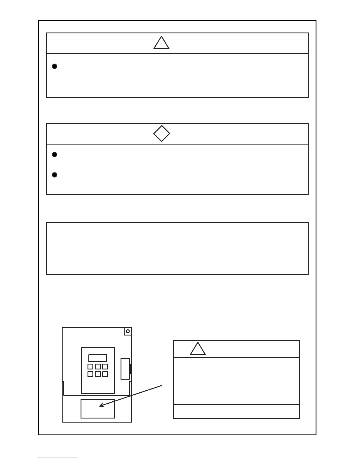
WARNING
ELECTEIC SHOCK RISK
˗
䃂
Disconnect supply and wait
䋵 minutes before working on
this equipment.
䋣
7. Warning Lable on Inverter
[Inverter Surface]
6
Note
!
Caution
Have an electrician periodically tighten the terminal screws.
Loosening of the terminal screws could lead to overheating or fire.
All diagrams in this instruction manual show the state with the cover
or safety partitions removed to explain the details. Before operating
the product, replace the covers and partitions to the positions specified,
and operate the unit according to the instruction manual.
!
Table of Contents
8
Special Precautions 9䊶10
Installation 11
䇶Page䇷
Outline Dimensions 12
Parts Identification 13䌾15
Wiring (Main Circuit) 16䊶17
Wiring(Control Circuit) 18䌾22
Operation(Basic Operation) 23䌾28
Function of each modes 29䌾33
Setting and Changing Function 34䊶35
Functional Descriptions (Parameter Table) 36䌾40
Functional Descriptions (By parameters) 41䌾73
Operation procedure of Custom mode 74䌾75
Resetting Fault Trips 90
Troubleshooting
㽲
91
Troubleshooting
㽳
92
Maintenance and Inspection 93䊶94
Specifications 95䌾97
Supplementary Explanation of Door
Width Measurement
76
Supplementary Explanation of Obstacle
Detection Function of the Door
77
Supplementary Explanation of
Communication Function
78䌾88
Individual Details and Remedies for
Fault Trips
89䊶90
7
Points for Handling
Points for Handling
Follow this manual and precautions when handling the inverter.
Incorrect handling could lead to inhibited operation or a drop operating
life. In the worst case, the inverter could be damaged.
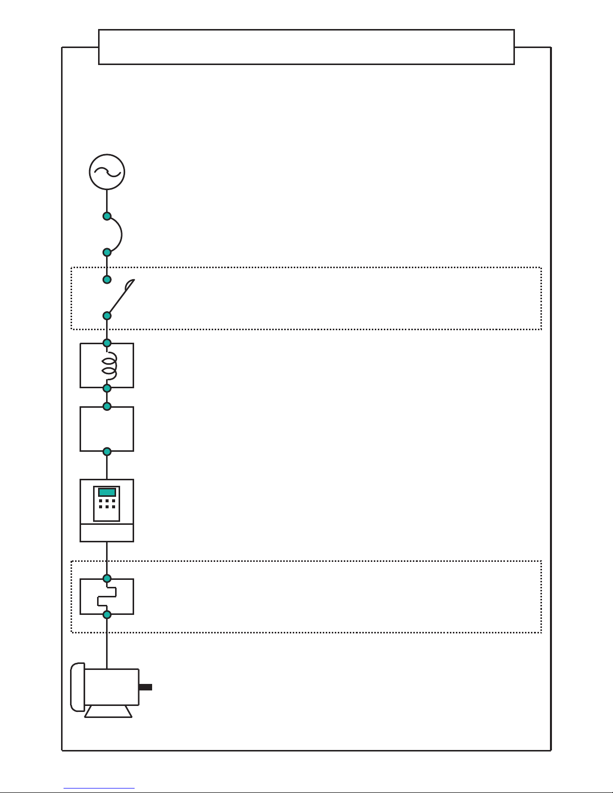
Power supply
Use within + 10%, -15% of the tolerable input
voltage range, and within 㫧5% of the tolerable
input frequency range.
Circuit breaker
MCCB
Size a breaker from the selection table on page 17.
Magnet
contactor
MC
A magnet contactor is not required in normal
use. If installed, do not start or stop the inverter
with the magnet contactor.
Power factor
improvement
reactor
Connect this when the power factor must be
improved.
Input noise
filter
Connect this when noise to the peripheral
devices is a problem.
N䊶F
Inverter
The ambient temperature is the most important
factor for the installation site. Make sure that the
tolerable value is not exceeded.
(See page 9 and 11)
Thermal relay
for open phase
protection
The thermal component built into the inverter is
used to protect against overloads. Use an open
phase protection thermal relay for open phase
protection.
Motor
3-phase induction motor.
8

Special Precautions
䂹㩷Use the inverter only within tolerable ambient temperature range.(-10㷄 to 50㷄)
Because the life of the inverter is greatly affected by ambient temperature,
use it within tolerable temperature range. Also, pay attention to the installation
directions and conditions. (See page 11)
䂹㩷To meet requirements of European standard directive, please refer to precautions
on Page 98.
䂹㩷The inverter will be damaged if the power voltage is applied to its output terminal.
Applying power voltage to the output terminal U, V or W will damage the inverter.
Check carefully for fault wiring and operation procedure.
䂹㩷Never touch the inside of the inverter during operation.
This is extremely dangerous the inverter contains high-voltage circuit. Be sure
to wait at least 5 minutes after the inverter power has been turned OFF, before
making an internal check.
Do not touch the heat sink fins or brake resistor during operation as these parts
will become hot during operation.
䂹㩷Radio interference
The main circuit of the inverter contains a higher harmonic component and may
interfere with communications equipment such as AM radios if these are used nearby.
The amount of radio interference depends on the field strength in the area where
the inverter is used. While it is difficult to completely eliminate radio interference,
it may be reduced by changing the angle of your radio antenna, using a noise
filter with the inverter, housing the inverter in a metallic shield box, or routing
inverter cables in metal conduit. ( Please inquire separately.)
䂹㩷Do not attempt insulation testing between the inverter cables.
To measure the insulation resistance of the power supply cables or the motor
cables, disconnect the inverter connecting wiries and test them with electric
connecting wires. Never conduct insulation testing on the control circuits by
megohm meter. However, insulation testing can be performed between the
charging unit and the ground.
䂹㩷If a magnetic contactor is connected to the power supply side or the load side
of the inverter, never use it to start or stop the motor (door controller).
Switching the inverter on the power supply side ON and OFF frequently by a magnetic
contactor, can cause the inverter to malfunction. Do not turn the inverter on the load
side ON and OFF during operation as this causes inverter fault trips. Start or stop
the motor only by means of inverter run signal.
䂹㩷Do not connect a power factor capacitor or suppressor to the output terminal
of the inverter.
Such devices can damage the inverter, its capacitors and other parts. Remove
the device if one is connected.
䂹㩷Never apply a power voltage that exceeds the tolerable voltage of the inverter.
9

䂹
䂹
Precautions regarding Inverter's Protection Function
Various protection functions such as stall prevention, current limit, overcurrent
shut-off are built in the inverter.
These protection functions are used to protect the inverter from the sudden
abnormal conditions in use, so they are not the control functions to be always
used.
Therefore, do not use the applications in which those protection functions
activate in the normal operating conditions.
In some cases, the inverter's life may be shorten, or the inverter may be
damaged.
Always measure the output current, etc. with a measuring instrument, and
check the details of the fault trip memory, and confirm that there is no problem
in the conditions for all the precautions and specifications describled in the
manual when using the inverter.
10
Do not use the inverter for loads other than a three-phase induction
motor.

Do not install or operate an inverter that is damaged or with parts missing.
Failure to do so could lead to injury.
[Install the inverter vertically]
䊶Areas subject to direct sunlight.
䊶Areas subject to water or high levels
of humidity.
䊶Areas with large amounts of oil mist,
dust or fiber dust.
䊶Areas where rain water, water drops
or oil drops may come in contact.
䊶Areas where corrosive gases, explosive
gases or flammable gases are present.
䊶Installation onto flammable materials such
as wood, or near flammable materials.
䊶Areas subject to vibration.
Installing the inverter in any other
way decreases its heat dissipation
effect and results in malfunction.
[Avoid installing the inverter in
the following locations]
Vertical Horizontal Sideways
[Make sure the ambient temperature
stays within the specifications]
The ambient temperature surrounding
the inverter will increase when it is
installed near a heating unit or housed
inside a panel. This may reduce the
life of the inverter. If you want to house
the inverter inside a panel, give careful
consideration to the cooling method
and panel size.
Space around the inverter
10cm or more
10cm or more
5cm
or more
5cm
or more
Inverter
11
Note
Installation
!
Install the unit on a non-combustible material such as metal.
Installing it on other material could lead to fire.
Do not place the unit near flammable materials.
Failure to do so could lead to fire.
Do not hold the terminal cover during transportation.
Failure to do so could cause the unit to drop and lead to injuries.
Do not allow foreign matter such as metal swarf enter the unit.
Entry of this type of matter could lead to fire.
Mount the unit according to the instruction manual in a place where
the weight can be withstood.
Failure to do so could lead to dropping of the unit and to injuries.
Tolerable ambient temperature:
-10 㷄㩷to 50㷄
(Ambient temperatures should be measured
at a point 5cm from the inverter.)

Unit: mm
Outline Dimensions
2䋭㱢5 ( Mounting holes)
90
100
121
130
126
5
12
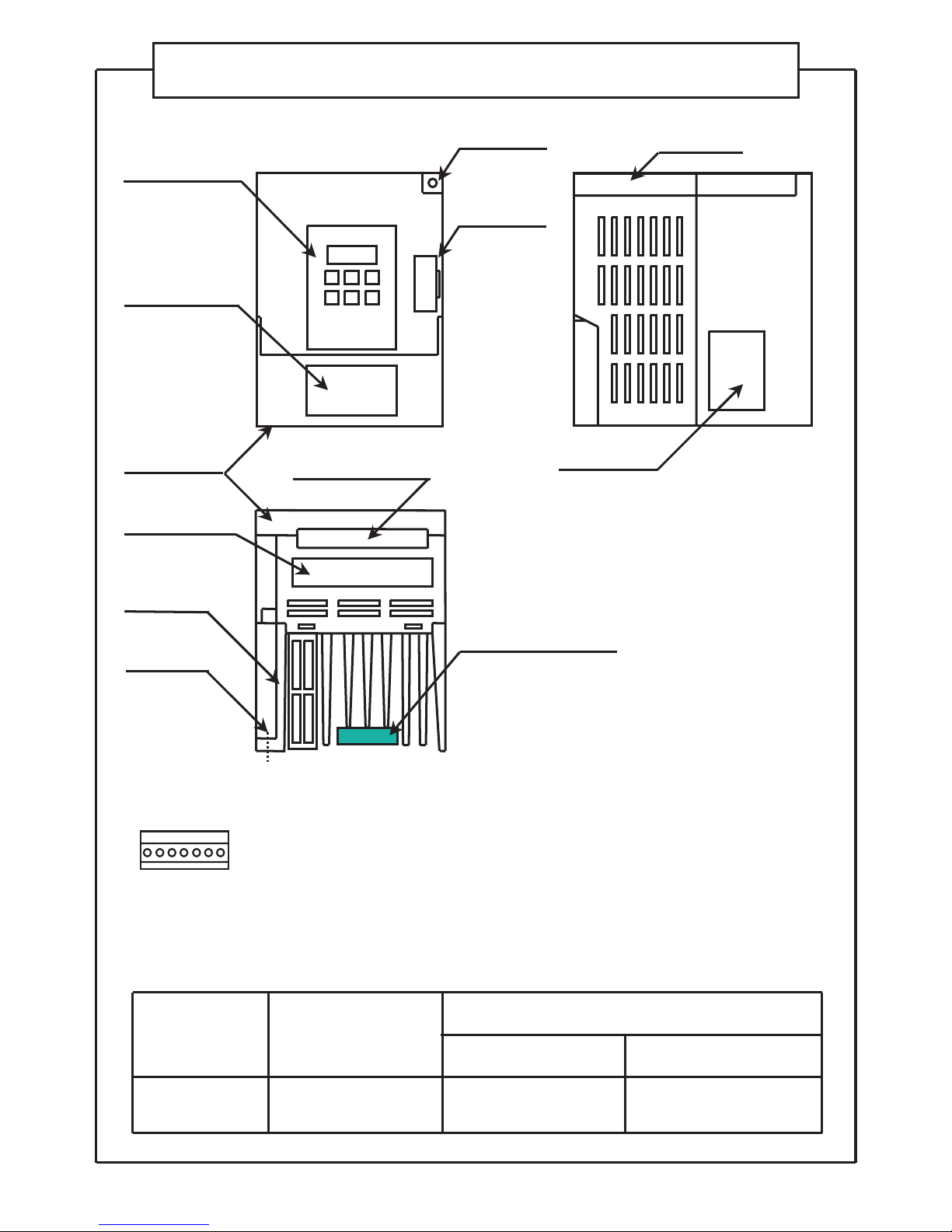
Warning label
Mounting hole
Terminal
cover
Mounting hole
Heat sink fins
Main circuit wire
lead-in hole
Control wire lead-in hole
Operation panel
Brake resistor
Communication
terminal cover
Note) The brake resistor is built into the
inverter with brakes only.
(Built into the heat sink fin section.)
[Accessory]
Communication terminal block (1 pc)
Note) Turn off the power supply and remove the communication terminal cover before
installing/ removing the communication terminal block. When the communication
function is not used, the communication terminal cover should be fitted.
䋪Check the rating nameplate to confirm
that the ordered product has been
delivered.
Frame
Rating
nameplate
Parts Identification
Input power
supply
Single-phase
200V
Applicable motor
capacity (kW)
0.4 AAD03011D
With brakes
Without brakes
AAD03011G
[Details on model]
13
Model

Explanation of Inside of Terminal Cover
Main circuit terminal block
Control circuit terminal
block (Relay output)
Earth terminal
Mounting hole
Control circuit terminal block
(Input and output signal)
Brake resistor
connecting terminal block
Note) This explanatory drawing shows
the state with the terminal cover
removed. During normal use, do
not remove the terminal cover.
Communication circuit terminal block
(RS485 communication)
㽲
㽲
㽳
Opening and Closing Terminal Cover
㽲 Opening the terminal cover
Lightly push up the cover bottom edge of the terminal cover.
㽳 Closing the terminal cover
Lightly push down the center top edge of the terminal cover.
Note) After closing the terminal cover, confirm that it is securely closed.
14
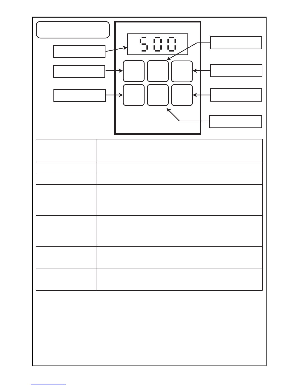
MODE
RUN
SET
STOP
䂥
䂯
MODE button
SET button
RUN button
STOP button
䂥㩿UP) button
䂯㩿DOWN) button
MODE button
This switch is used to change to each "output frequency,
output current display", "frequency setting, control status
monitor", "rotation direction setting", "function setting" mode,
and to switch the display from the data to mode display.
SET button
The switch is used to change the display between the mode
and data display, and to save the data. In the "Output
frequency, output current display mode", this switch changes
the display between the frequency and current.
䂥㩿
UP) button
This switch is used to change the data or output frequency,
and to set forward run direction when carrying out forward
rotation with the operation panel.
䂯㩿
DOWN) button
This switch is used to change the data or output frequency,
and to set reverse run direction when carrying out reverse
rotation with the operation panel.
䊶
Main display
Hz
STOP button
The switch is used to stop the inverter.
RUN button
The switch is used to start the inverter.
Main display
Handling for the displays of output current, output voltage and internal
DC voltage.
1˅The displayed output current, output voltage and internal DC voltage are not
intended for precise measurement. Use this only as a guide value.
(Use a separate measuring instrument when precise values are required.)
2˅Especially for the displayed output current, a relatively large value may be
displayed at approx.40% or less of the rated current. (For example, even if there
is no output current, a certain level may be displayed. Note that when the
inverter is stopped, "0.0A" will be displayed.)
15
Explanation of
Operation Panel
The output frequency, output current, line speed, control
status monitor, data for function setting and parameter No.
are displayed.

䋣
Caution
Always confirm that the input power is OFF before starting wiring. Wait
at least five minutes after turning the input power OFF before starting wiring.
Failure to do so could lead to electric shocks, fires or injuries.
Wiring work must be carried out by a qualified technician.
Failure to do so could lead to electric shocks, fires or injuries.
Always install the unit before wiring.
Failure to do so could lead to electric shocks or injuries.
Note
䋣
Do not connect an AC power supply to the output terminals (U, V, W).
Doing so could lead to injuries or fire.
Confirm that the product's rated voltage and the AC power supply voltage match.
Failure to do so could lead to injuries or fire.
Tighten the terminal screws with the designated tightening tool.
Failure to do so could lead to fire.
Always connect the earth.
Failure to do so could lead to electric shocks, fires or injuries.
䂓 Precautions on wiring
Note the following points carefully to prevent miswiring and misuse of the inverter.
(Devices may be broken.)
1Connect the power supply to input terminals (L, N) and the motor to output
terminals (U,V,W).
2Use sleeved round crimp terminals for power supply and motor terminals.
3After wiring the main circuit, double check for tightness as access will be limited
once control circuit wiring is in place.
4When connecting directly to a large capacity power transformer (500kVA or more),
always install a power factor improvement reactor on the inverter's input side.
5Select connected devices and wire size according to the table on page 17.
6Class D(3) grounding must be done.
7To meet requirements of CE Marking, power input end of the inverter shall be
equipped with protection devices for overcurrent, short circuit and leakage of
electricity.
Connect the correct wiring for the motor. If the wiring is incorrect, the door
control cannot operate properly.
Wrong connection could lead to injuries or fires.
16
Wiring (Main Circuit)

䂓 Connected Device, Wire Size and Main Circuit Terminal
Tightening Torque
Note1) If the breaker's overcurrent trip is a magnetic type, the device could overheat
due to higher harmonics. Use a load rate of 50% or less in this case.
Note2) When using an installed circuit breaker with motor protection, remove it.
Inverter capacity Circuit breaker
Wire size
2mm
䌻 14AWG䌽
2
Tightening torque
1.2 N䊶m0.4 kW
BC䋭30N 10A
䂓 Wiring (Main Circuit Terminal)
Power
supply
Circuit breaker
(MCCB)
䌌 䌎
䌕 䌖 䌗
Motor
IM
Ground
terminal
Main circuit terminals
Brake resistor
Brake resistor
connection
terminal
䇶 Screw size䇷
Ground marking
Main circuit terminal: M4 Grounding terminal: M4
1When using the regenerative brake, select the one with brakes. The brake
resistor is built in the inverter. (It is built in the radiation fin.)
2When using regenerative brakes, set the parameter P17 data to"0".
The brakes will not activate when the factory setting "1" is set.
3The regenerative brake specifications are shown below. Carefully consider
the working conditions before using these brakes.
Note that the inverter could be damaged if the specifications are exceeded.
䊶Maximum duty factor (%ED): 2%
䂓 Precautions for Using Regenerative Brakes
Note) Always connect protective devices such as fuse for overcurrent, short circuits
and leakage protection to the input terminal.
17
Class D(3) grounding
䊶Maximum working time: 3s
䊶Maximum torque: 100%
Control Circuit Wiring
䂓 Wiring (Control Circuit Terminal)
䂹 Built-in power supply specification: 12 V DC -10%/ +20%, 0.1A or less
To meet requirements of European standard directive, please refer to
precautions on Page 98.
䂹 Relay output contact specifications:
1c no-voltage contact, 230 V AC 0.3 A, 30 V DC 0.3 A(resistance load)
Mechanical lifetime: 100 million times or more(switching frequency: 180 times/min.)
Electrical lifetime: 100 thousand times or more(switching frequency at rated
control capacity: 20 times/min.)
Note1) Do not use the Built-in power supply for other devices except for the
encoder power supply. The inverter could be damaged if the
Built-in
power supply is connected incorrectly.
Note2) The NPN open collector output should be used for the output signals
(phase A and phase B) of the encoder. Please read the precautions
on the encoder. (See page 21 and page 22)
Note3) The common terminals(㽹and㽽) are connected within the inverter.
Do not ground the common terminal.
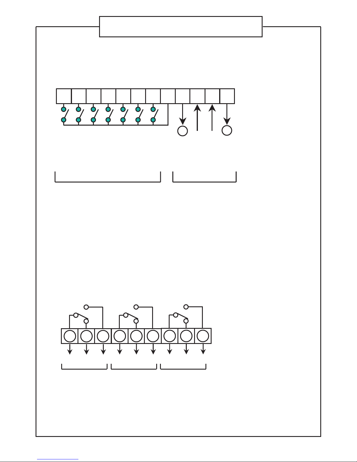
Open signal
CommonCommon
Close signal
Open arrival signal
Close arrival signal
Safety sensor
Open speed
change signal
Close speed
change signal
Phase A signal
Phase B signal
Built-in power
supply
Built-in power
supply
Input signal Encoder signal
䂓 Wiring (Output terminals)
Relay 1 output
C1
COM NC NO
B1 A1
C2
COM NC NO
B2 A2
C3
COM NC NO
B3 A3
Relay 2 output Relay 3 output
18
㽲㽳㽴 㽶㽷㽸㽹㽺 㽼㽽
䋭
䋫
㽵 㽻

[Wiring Method]
䊶For the wiring of the control circuit terminals, use the electric wires after removing the
specific size of wire's insulation.
䊶 Loosening the interminal screws and insert the cables from under the terminal block,
and tighten the screws with a specific torque.
Note1) Twist the strands of the uncovered electric wires.
Do not solder them.
Note2) Tightening loosely causes the wires to be come away or malfunctions.
Tightening too hard causes the short-circuit or malfunctions caused by the
damage to the screw or the inverter.
䂓 Wiring ( Communication Terminals)
Terminator
D䋫
D䋭
䌅
V䋫
V䋭
䌅
V䋫
V䋭
D䋫
D䋭
䌅
V䋫
V䋭
D䋫
D䋭
D䋫
D䋭
D䋫
D䋭
D䋫
D䋭
Short
circuit
Transition connecting wire: Max. 500m
䌄䋫䋺㩷Transmission line + terminal
(RS485 communication)
䌄䋭䋺㩷Transmission line - terminal
(RS485 communication)
䌅䋺㩷Terminator terminal
(RS485 communication)
䋪 Related parameter No. P35 to P40.
䋪 Connect the D+ side and D+ side, and
D- side and D- side of the communication
terminals.
䋪 The D- side and E side of the inverter to
be a terminator should be shorted.
Do not short the units other than the
terminator.
䋪 Do not use the V+ and V- terminals.
Always leave them open. If they are
connected incorrectly, the inverter
could be damaged.
䂹 Terminals to connect personal computers and PLCs by the RS485
communication.
RS485
Terminal
mark
Screw
size
Tightening
torque N䊶m
Cable size
A1 -3䋬B1 -3
C1- 3
M3
㽲䌾㽽
M2
0.5䌾 0.6
0.25䌾0.75 mm
2
(AWG24䌾AWG18)
0.22䌾 0.25
0.25䌾0.75 mm
2
(AWG24䌾AWG18)
䂓 Electric Cable Size and Control Circuit Terminal
Tightening Torque
Wire's insulation
removing size
6mm
5mm
䊶Screwdriver: Small-size 㰵screwdriver
(Depth of the edge: 0.4mm/ Width of the edge: 2.5mm)
䊶Wire's insulation
removing size
D䋫㪃 D䋭㪃 E
V䋫㪃 V䋭
M2
0.22䌾 0.25
0.25䌾0.75 mm
2
(AWG24䌾AWG18)
7mm
19

䂓 Explanation of Control Circuit Terminals
Terminal
No.
Terminal Function
Related Parameter
No.
Ԙ
Input terminal of Open Signal
(forward run operation)
P08
ԙ
Input terminal of Close Signal
(reverse run operation)
P08
Ԛ
Input terminal of Open arrival signal
ԛ
Input terminal of Close arrival signal
Ԝ
Input terminal of safety sensor
P43,P44
ԝ
Input terminal of Open speed change signal
Ԟ
Input terminal of Close speed change signal P09,P43,d50
P09,P46,P52
P09,P46,P52
ԟ
Common terminal of input signal 1 to 7
Ԡ
ԡ
Input terminal of encoder (phase A) signal
Ԣ
Input terminal of encoder (phase B) signal
ԣ
A 1
Relay 1 contact output terminal (NO: at factory setting)
P48
B 1
Relay 1 contact output terminal (NC: at factory setting)
P48
C 1
Relay 1 contact output terminal (COM) P48
A 2
Relay 2 contact output terminal (NO: at factory setting) P49
B 2
Relay 2 contact output terminal (NC: at factory setting) P49
C 2
Relay 2 contact output terminal (COM) P49
A 3
Relay 3 contact output terminal (NO: at factory setting) P50
B 3
Relay 3 contact output terminal (NC: at factory setting) P50
C 3
Relay 3 contact output terminal (COM) P50
D㧗
Transmission line + terminal
(RS485 serial communication signal)
P35 to P40
D㧙
Transmission line - terminal
(RS485 serial communication signal)
P35 to P40
E
Terminal for setting terminator
(Transmission line- terminal and short-circuit)
Do not short the units other than the terminator.
V㧗
Unused terminal
V㧙
Unused terminal
20
P43,P45,P47,P76,
d49
P09,P43,d48
P43,P45,P47,P76,
d47
Built-in power supply (+) terminal (12 V DC)
Built-in power supply (-) terminal (12 V DC
common terminal)
䂓 Precautions on Wiring
1. Use shielded wires for all control signal wires and keep them away
more than 20cm from power lines and strong electric circuits.
2. The wiring length of the control signal wire is 30m or less.
3. The control circuit's input signal is a minute signal, so use two minute
signal contacts in parallel or use a twin contact to prevent contact
faults when inputting the contact.
4. No-voltage contact signal or open-collector signal should be used with
control terminals No. 1 to 7.
(If a voltage is applied across these terminals, the inverter may be damaged.)
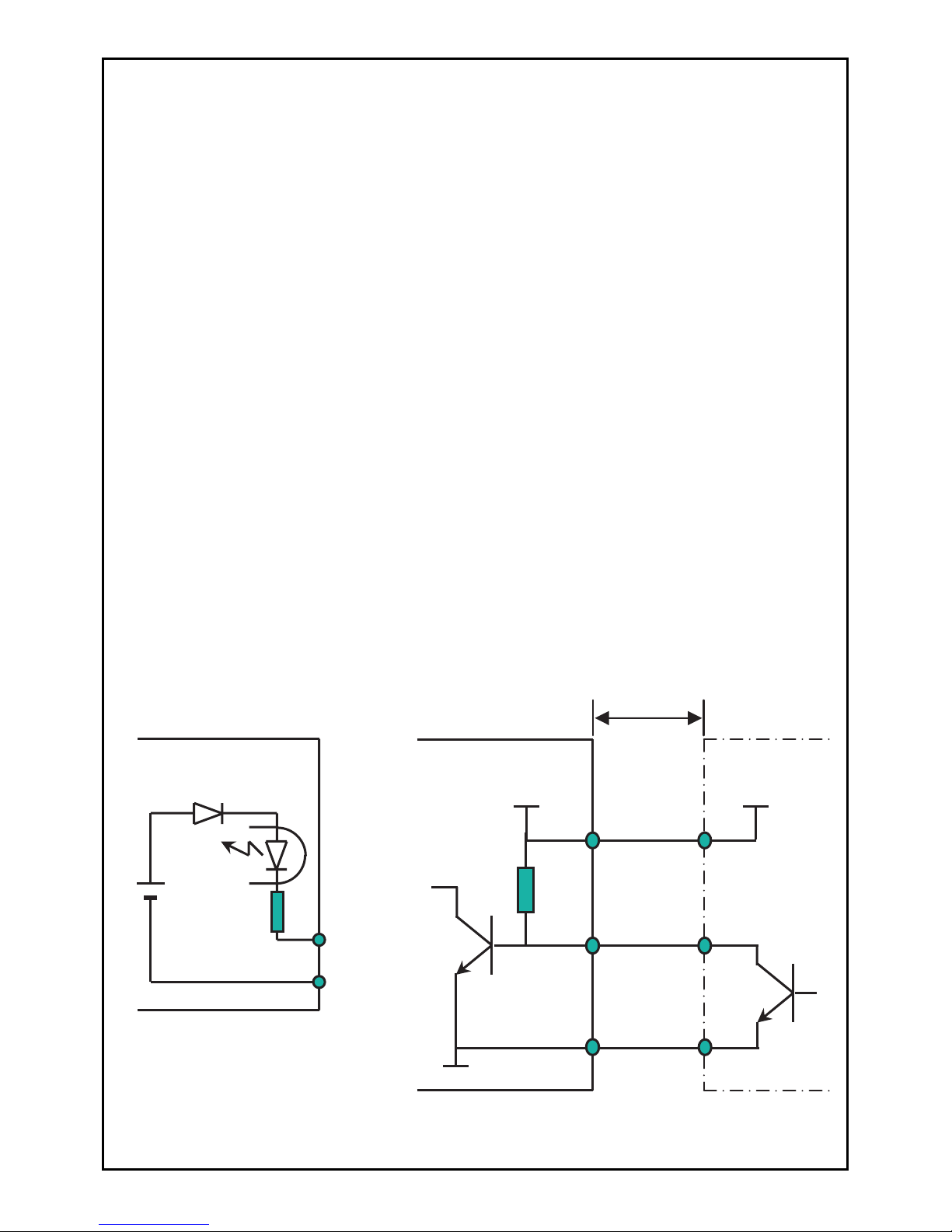
䋪㩷Input circuit specifications are shown in Fig. 1.
Take special care to avoid loop or leakage current.
12V DC
2k 㱅
Terminals
No. 1 to 7
Inverter internal
circuit
Terminals
No. 8
Inverter internal
circuit
Terminals
No.12
Encoder
Common
Terminals
No.10, 11
Terminals
No.9
VCC
Output(Phase A,
Phase B)
12V DC
2k 㱅
Leghth of wiring
Max. 5m
Fig. 1
Fig. 2
5. Precautions on encoder (Refer to Fig.2 and 3)
Note1) NPN open-collector output is used with ouput signal
(Phase A, Phase B) of the encoder.
Use the transistor that meets the specifications below.
䊶 Max. rated voltage : 30VDC or more
䊶 Rated current : 20mA or more
Note 2) Power supply of the encoder should be 12 V DC -10%/ ˇ20%.
Note 3) Consumption current of the encoder should be 50mA or less.
21
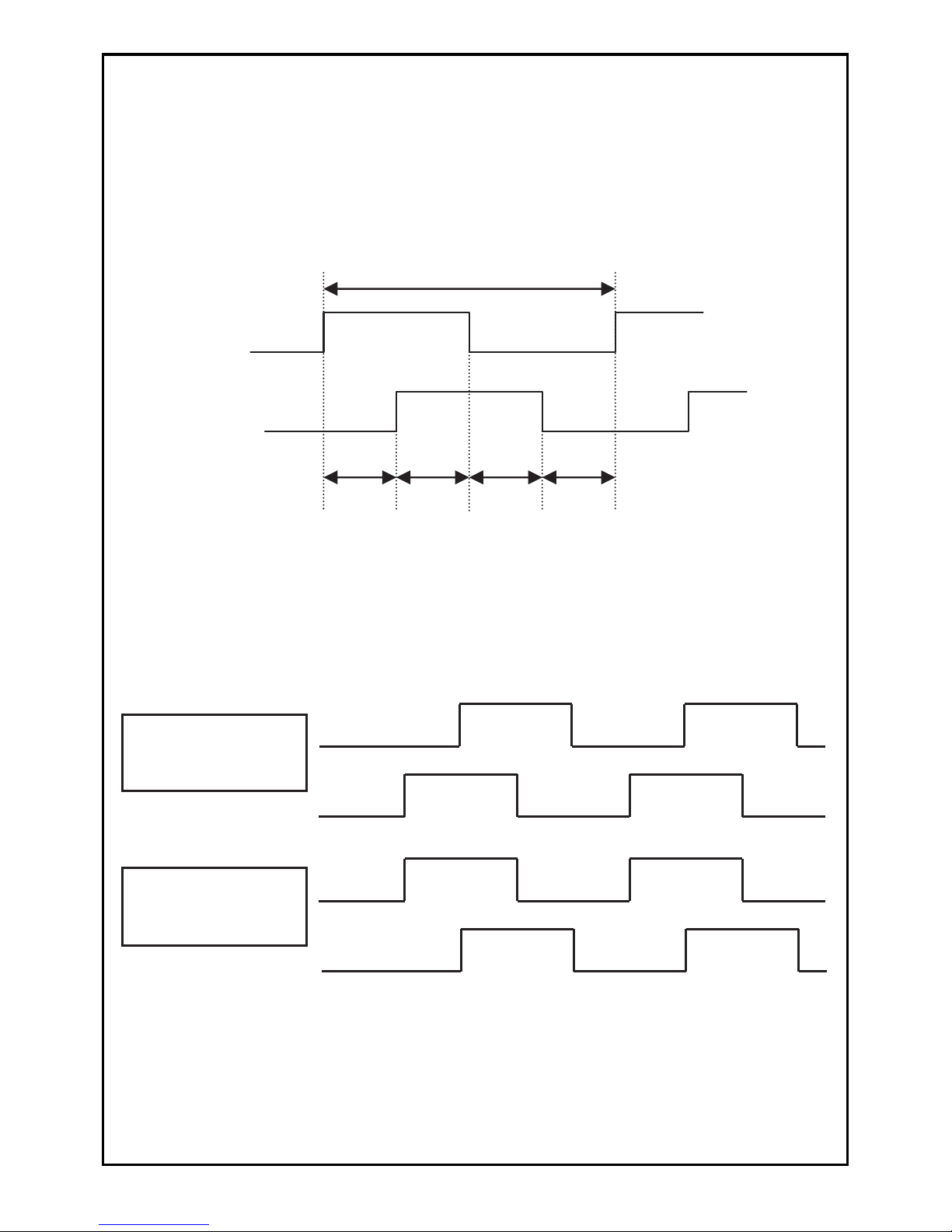
Phase A
Phase B
Phase A
Phase B
Phase A
Phase B
t1 t2 t1 t2
䌔
Note5) The max. input pulse frequency and the min. input pulse width
should be used at the following setting.
䊶㩷Max. input pulse frequency (1/T) : 10 kHz or less
䊶㩷Overlap (t2) : 25㱘s or more
Note6) Confirm the rotation direction before making the connection of
the output signal (phase A and phase B) of the encoder.
Fig. 3
6. For the communication cable, use a double-core cable(VCTF) or
twisted pair cable ( with shield). Keep the cable away from power
lines and strong electric circuits.
Note4) Control the cable wiring length of the encoder within 5m or less.
7. The total length of the communication cable must be 500m or less.
[Judging the pulse signals of phase A and B, and forward/
reverse directions]
Open operation in
forward direction
(Count addition)
Close operation in
reverse direction
(Count subtraction)
22
䊶㩷Phase difference (t1): 25㱘s or more

Operation (Basic Operation)
Always close the terminal cover before turning the input power ON.
Do not open the terminal cover while the power is ON.
Failure to do so could lead to electric shock.
Do not operate the buttons with wet hands.
Failure to do so could lead to electric shock.
Do not touch the inverter terminals when the inverter power is ON or even
when the inverter is stopped.
Failure to do so could lead to electric shock.
The STOP button is not designed for emergency stop purposes.
Prepare a separate emergency stop switch.
Failure to do so could lead to electric shock.
Always confirm the security and function operation of the elevator system
before obstacle detection function is applied.
Failure to do so could lead to injury.
Make sure to input safety sensor in the main controller of the elevator and
to operate the door's obstacle detection on the main controller side.
Obstacle detection function of the inverter does not operate in the CLOSE
arrival area.
Always take dual security measures.
Failure to do so could lead to injury.
Make sure to input arrival signal (limit switch etc.) in the main controller of
the lift and to operate the door's obstacle detection on the main controller side.
Do not operate obstacle detection of the door only with OPEN/CLOSE arrival
signal (input signal and the relay's output signal).
Failure to do so could lead to injury.
Depending on different settings of the fault OPEN operation forced operation
time and the stop selection of OPEN/CLOSE operation, sometimes even
OPEN/ CLOSE signal are both turned OFF, the door does not stop.
Confirm the lift's security and function operation before using this equipment.
(Secure personal safety before carrying out the operation.)
Failure to do so could lead to injury.
Due to setting of the start mode and the ride-through restart function, when
the run signal is ON, the inverter may start (restart) suddenly if the power
is applied or the power is restored after a power failure. Keep out of the
working part of the motor and the machine.
Design the machine so that personal safety can
be ensured even if the inverter starts suddenly.
Failure to so could lead to injury.
23
!
Caution
䈀㩷㩷㩷㩷㩷㩷㩷㩷㩷㩷㩷㩷㩷㩷㩷㩷㩷㩷㩷㩷㩷㩷㩷㩷㩷㩷㩷㩷䈁
The heat sink fins and brake resistor can reach high temperatures, so do
not touch them.
Doing so could lead to burns.
The inverter can be easily set to run from low speeds to high speeds.
Confirm the tolerable range of the motor and machine before starting operation.
Failure to do so could lead to injure.
Prepare holding brakes if required.
Failure to do so could lead to injure.
Before turning power ON, check the following points again.
ķ Check that all wiring is correct.
Reversed wiring between the power supply and the load, in particular,
can result in damage to the inverter.
ĸ Make sure the inverter rating and power supply voltages match each other.
Ĺ Make sure no power factor capacitor is connected to the motor, as it can
damage the inverter and the capacitor.
ĺ Before starting a trial run, check the set frequency.
Depending on the start mode function setting, if "the fault trip is reset" or
"the stop state is released with the panel STOP function" or "door width
measurement is reset" when the run signal is input, the inverter may restart
suddenly.
(Secure personal safety before using this function.)
Failure to do so could lead to injury.
When the retry function is used, the inverter may automatically start (restart).
Keep out of the working part of the motor and the machine.
(Secure personal safety before using this function.)
Failure to so could lead to injury.
If there is no arrival signal, start operation before ensuring the security and
function operation of the lift system.
(Secure personal safety before starting operation.)
Failure to do so could lead to injury.
When carrying out the door repeat control and the door width measurement,
the operation direction of the door may change automatically. Start operation
after ensuring personal safety.
Failure to do so could lead to injury.
Adjust and confirm each parameter before operating. Depending on the
settings of the parameters, the inverter may work unexpectedly.
Failure to do so could lead to injure.
24
Note
!
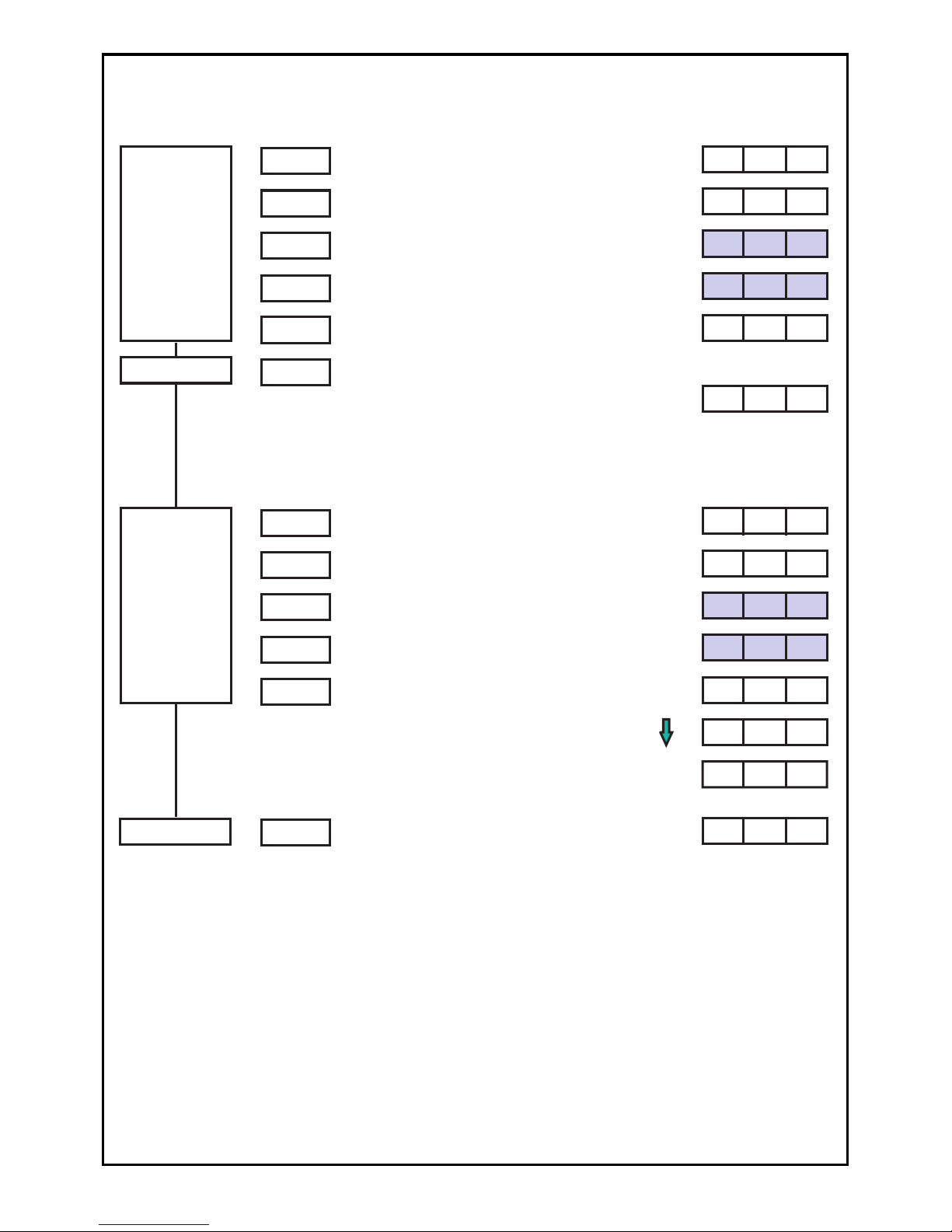
Setting the Frequency and Forward/Reverse Run
Function With the Operation Panel
There are following methods for setting the frequency and carrying
out forward/reverse run function with the operation panel.
䊶Frequency setting: [Digital setting method]
䊶Forward/reverse run operation: [Forward run/reverse run method]
[Start/stop, rotation direction mode setting method]
1ˊSetting the frequency
1˅Digital setting method (Parameter P09 set to "0")
Press the MODE button on the panel to enter the frequency setting mode (Fr).
Press the SET button, display the frequency to be set with theƷ(up) button
and(down) button, and then press the SET button to enter the data.
The frequency can be changed by holding down theƷ(up) button or(down)
button during operation. (Hereafter, this function is called the MOP function.)
This MOP function cannot be used when parameter P08 is set to "1".
2ˊForward/reverse run function
1˅Forward run/reverse run method (Parameter P08 set to "1")
2˅Sart/stop, rotating direction mode setting method (Parameter P08 set to "0")
First, press the MODE button twice to enter the rotation direction setting
mode (dr). Press the SET button to display the rotation direction data, change
the rotation direction with theƷ(up) button and(down) button, and then press
the SET button to enter the data. (Forward run is set as the factory setting.)
Operation will start when the RUN button is pressed, and will stop when the
STOP button is pressed.
Start/stop, rotation direction
mode setting method
Forward run/reverse
run method
Forward/reverse
run function
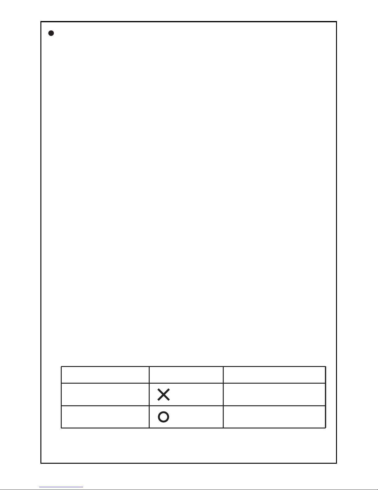
3ˊCombination of "Mop function", "rotation direction setting mode"
and forward/ reverse run function.
Note) When the forward run/reverse run function is set to "forward run/reverse
run method (parameter P08=1) ", the MOP function cannot be used.
MOP function
(Cannot be used)
(Can be used)
Details of rotation direction
setting mode
Only monitor function
Monitor function and direction
setting function
Note) In the case of the door control, the forward run operation is OPEN
operation and the reverse run operation is CLOSE operation.
25
Press theƷbutton (forward run) orbutton (reverse run) on the panel
to select the rotation direction. Operation will start when the RUN button
is pressed, and will stop when the STOP button is pressed.
䋪The inverter will not start running just by pressing the RUN button.

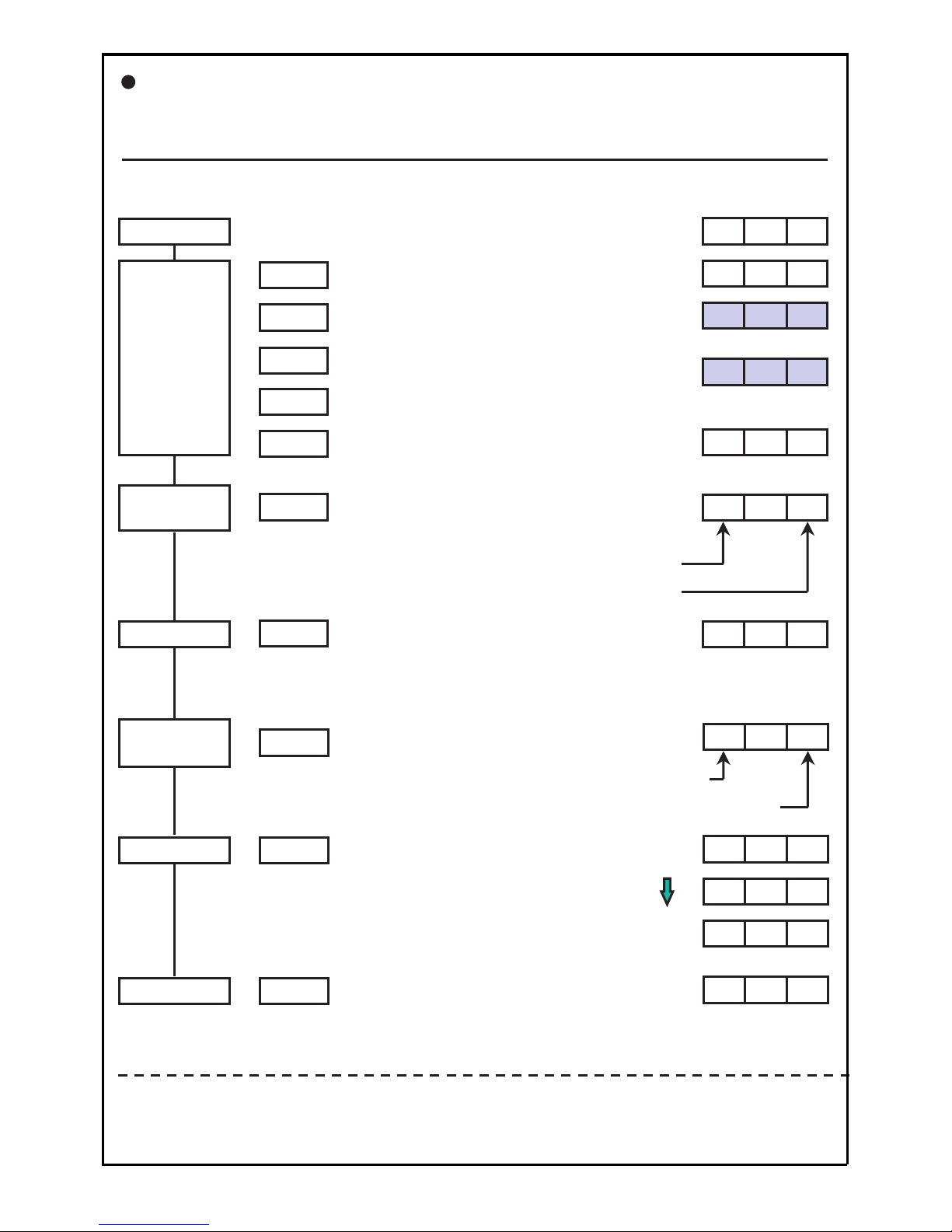
Operating With the Operation Panel -1 (Factory Setting State)
䊶Frequency setting: Digital setting (Parameter P09=0)
䊶Forward /reverse run function: Start/stop, rotation direction mode setting (Parameter P08=0)
Power ON
Frequency
setting
Press the MODE button.
0 5. 0
r
䂥
Run command
Press the SET button.
(The main display will flicker.)
The main display lamp will turn ON.
000
[Example for rotating in forward direction at operating frequency 5Hz]
Stop command
Press the STOP button. The motor will
start to decelerate and will stop.
STOP
0 00
MODE
SET
F
0 0. 5
䂯
Press theƷ(up) or(down) buttons
to display 5Hz on the main display.
(The main display will flicker.)
Press the SET button to set the data.
SET
0 00
Press the RUN button.
As the factory setting is the forward
operation, the motor will start rotating in
the forward direction and operate at 5Hz.
RUN
0 5. 0
[Example for rotating in forward direction at operating frequency 10Hz]
Changing the
frequency
during
operation
Press the MODE button.
1 0. 0
r
䂥
Press the SET button.
(The main display will flicker.)
MODE
SET
F
0 5. 0
䂯
Press theƷ(up) or(down) buttons
to display 10Hz on the main display.
(The main display will flicker.)
Press the SET button to set the data.
The display will change to the output
frequency, and will reach 10Hz.
SET
1 0. 0
[Stopping operation]
[Changing the frequency with theƷandbuttons during operation (MOP function)]
The operating frequency can be changed with theƷandbuttons during operation.
䊶 If theƷ(up) button is held down, the operating frequency will increase.
䊶 If the(down) button is held down, the operating frequency will decrease.
Note ) Once the operating frequency is determined, press the MODE button and then
press the SET button twice to set the operating frequency.
If this is not carried out, this frequency will not be saved when the power is
turned OFF.
Main display
26
Main display
[Continued from previous page, Example for rotating in reverse
direction at operating frequency 10Hz]
Changing
the rotation
direction
Press the MODE button.
r
Press the SET button.
(The main display will flicker.)
MODE
SET
F
䂥
Press the䂥(up) button.
(The main display will flicker.)
Press the SET button to set the data.
SET
0 00
Press the MODE button.
r
MODE
d
䋭 FL
䋭 rL
Run command
Stop command
Press the RUN button.
As the frequency is already set to
10Hz, the motor will start rotating in
the reverse direction and operate
at 10Hz.
RUN
1 0. 0
[Example to change to forward rotation during reverse rotation]
Changing
the rotation
direction
Press the MODE button.
r
Press the SET button.
(The main display will flicker.)
MODE
SET
F
䂯
Press the䂯(down) button.
(The main display will flicker.)
Press the SET button.
The motor will decelerate, and
will start forward rotation at 10Hz.
SET
Press the MODE button.
r
MODE
d
䋭 rL
䋭 FL
1 0. 0
0. 0
Reverse
Forward
1 0. 0
Press the STOP button.
The motor will start to decelerate
and will stop.
STOP
0 00
[Stopping operation]
27
Operating With the Operation Panel -2
䊶Frequency setting: Digital setting (Parameter P09=0)
䊶Forward / reverse run function: Forward run/reverse run operation (Parameter P08=1)
r
[Example to change from forward run to reverse run during operation]
[Stopping operation]
Press the STOP button.
The motor will start to decelerate
and will stop.
STOP
0 00
Reverse run
setting
Press the䂯(down) button, and set
the rotation direction to reverse run.
䋭F
䂯
Run command
Stop command
Press the RUN button.
The motor will gradually decelerate,
and will start forward rotation at
5Hz again.
RUN
5. 0
0. 0
5. 0
Forward
Reverse
[Canceling the rotation direction setting]
After setting with the䂥and䂯buttons, the rotation direction can be canceled by pressing
the same button again.
Note) If the RUN button is pressed after setting the rotation direction, the rotation
direction will not changed.
Power ON
Forward run
setting
Press the䂥(up) button, and set the
rotation direction to forward run.
(Press the䂯button to set reverse run.)
䋭
F0
䂥
Run command
Press the RUN button.
The motor will start rotating in the
forward direction and operate at 5Hz.
RUN
5. 0
The main display lamp will turn ON.
000
[Example for rotating in forward direction at operating frequency 5Hz]
䊶Set rotation direction (F: Forward run, r: Reverse run)
䊶Current state (0: Stop, F: Forward run, r: Reverse run)
䊶Set rotation direction (r: Reverse run)
䊶Current state (F: Forward run)
Frequency
setting
Press the MODE button.
0 5. 0
r
䂥
Press the SET button.
(The main display will flicker.)
MODE
SET
F
0 0. 5
䂯
Press the 䂥(up) and䂯(down) buttons
to display 5Hz on the main display.
(The main display will flicker.)
Press the SET button to set the data.
SET
0 00
Main display
28
 Loading...