

Page 1
MICRO-IMAGECHECKER® A210•A110 MultiChecker V2 Series
11/2004
11/2004
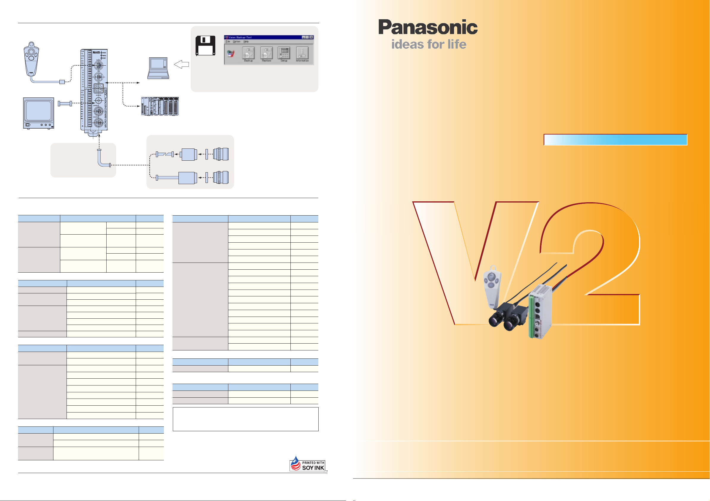
■ System configuration diagram
*1
Serial cable
ENTER
A
B
C
Panasonic
Monitor
Keypad
Monitor cable
(Pin-BNC)
CONTRAST
V-HOLD BLIGHT
Video Monitor GP-BM
Camera extension cable
*2
Controller
PC
PLC (refer to P5)
High-speed
random cable
*3
■ Vision Backup-Tool Ver.2
The product data created with the MICRO-IMAGECHECKER A
series and the image data stored in the controller can be stored
on a PC using Windows.
Stored data can be restored to the A series controller.
However, it is not possible to directly restore type data backed up using
*
Vision Backup-Tool with the previous product (Ver. 1) to V2 (Ver. 2). In
this case, use the dedicated data conversion software (freeware) to
convert the Ver. 1 type data for V2 use, then transfer it to V2 and perform
a backup again. If you require the data conversion software, contact your
Matsushita Automation Controls Co. Ltd. representative.
High-speed
random trigger camera
CS mount camera
Middle ring
Lens
*1 The A100 series connects to one camera.
*2 Use where necessary.
*3 When using 2 cameras with the A200 series,
connect the same type of camera.
Image Processing Device
®
MICRO-IMAGECHECKER
•
A210
MultiChecker Ver.2 Series
A110
■ Table of Product Numbers
● MICRO-IMAGECHECKER A-Series Controller
Item
A210
MICRO-IMAGECHECKER
A200 Series
MICRO-IMAGECHECKER
A100 Series
Multi-Checker V2 : CE
A210
Multi-Checker : CE
A110
Multi-Checker V2 : CE
A110
Multi-Checker : CE
● Camera / Keypad / Monitor
Item
C mount camera
CS mount camera
Keypad
Monitor
● Camera cable
Item Specifications
Double-speed random
camera cable
Camera extension cable
● Serial Cable
COM port
connecting cable
TOOL port
connecting cable
COM port and PC (D-SUB : 9 pin) connection, 3 m
COM port and PLC (discrete-wire cable) connection, 3 m
COM port and PC (D-SUB : 9 pin) connection, 10 cm
Matsushita Electric Works, Ltd.
쮿
Head Office: 1048, Kadoma, Kadoma-shi, Osaka 571-8686, Japan
ARCT1B178E 200111-2YT
Specifications Part No.
NPN Output
PhotoMos Output
NPN Output
NPN Output
PhotoMos Output
NPN Output
Specifications
Progressive Double-speed Random: CE
support electric-shutter with 3 m cable
support electric-shutter with 3 m cable: CE
with 2 m cable
with 3 m cable
with 2 m cable: CE
with 3 m cable: CE
Panasonic GPBM910 (100 V AC/12 V DC)
3 m
3 m: CE
2 m extension: total 5 m
7 m extension : total 10 m
12 m extension: total 15 m
17 m extension: total 20 m
2 m extension : total 5 m: CE
7 m extension: total 10 m: CE
12 m extension: total 15 m: CE
17 m extension: total 20 m: CE
Specifications
Automation Controls Company
ANMA212V2
ANMA218V2
ANMA212
ANMA112V2
ANMA118V2
ANMA112
Part No.
ANM831
ANM832
ANM832CE
ANM85202
ANM85203
ANM85202CE
ANM85203CE
AUGPBM910
Part No.
ANM84303
ANM84303CE
ANM84002
ANM84007
ANM84012
ANM84017
ANM84002CE
ANM84007CE
ANM84012CE
ANM84017CE
Part No.Item
ANM81103
ANM81303
ANM812001
These materials are printed on ECF pulp.
These materials are printed with earth-friendly vegetable-based (soybean oil) ink.
● Lens / middle ring
Item Specifications
CS mount lens
C mount lens
Middle ring
f2.8 CS mount compact lens
f2.8 CS mount compact lens with lock
f4 CS mount compact lens
f4 CS mount compact lens with lock
f8 CS mount compact lens
f8 CS mount compact lens with lock
f6.5 C mount lens
f8.5 C mount lens
f8.5 C mount lens with lock
f16 C mount compact lens
f16 C mount compact lens with lock
f25 C mount compact lens
f25 C mount compact lens with lock
f50 C mount lens
f50 C mount lens with lock
f50 C mount compact lens
f50 C mount compact lens with lock
5 mm middle ring
(0.5/1/5/10/20/40 mm) middle ring
Part No.
ANM8828
ANM88281
ANM8804
ANM88041
ANM8808
ANM88081
ANB842
ANB843
ANB843L
ANB845N
ANB845NL
ANB846N
ANB846NL
ANB847
ANB847L
ANM8850
ANM88501
ANB84805
ANB848
● Data backup software
Item Specifications
Vision Backup-Tool Ver.2 English version
Microsoft windows NT4.0/95/98/Me/2000 compatible. An operating system is not included with this software.
Part No.
ANM70131V2
● Accessories
Item Specifications
I/O terminal block
BNC connector
Unless otherwise specified, estimate and delivery prices do not include technician dispatching
and other related services. Therefore, for the situations given below, additional charges
may be added.
• Installation and trial operation guidance • Inspections, adjustments, and repairs
• Technical support and instruction
To USA Customer
• Products sold by seller are covered by the warranty and patent
indemnification provisions in its Terms and Conditions of Sale only.
For input: 1 piece, for output, 1 piece
Monitor BNC jack to PIN jack adapter
COPYRIGHT © 2001 All Rights Reserved
Specifications are subject to change without notice.
Part No.
ANMA8001
ANM8606
It won’t stop advancing. The monstrously small A Series!
Page 2
The MultiChecker V2 Series - more powerful
11/2004
11/2004
than ever!
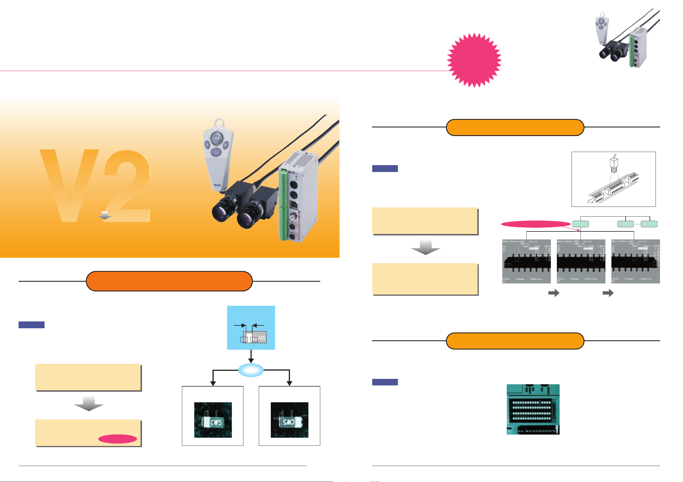
Our highly acclaimed, compact A210 and A110 MultiChecker image processing units are now even more powerful! The V2
(Ver. 2) upgrade includes new functions for even greater convenience. To meet your diverse range of inspection
requirements, we have increased the number of checkers by a factor of three. In addition to making more inspection locations
possible, they now come equipped with a new mode that allows two-level branch inspection using one image checker, and an
extensive range of functions that allow use in a wide range of applications.
New
New
User-Defined Mode
Three times the processing capacity
of their predecessors!
Designed to meet a diverse variety of
inspection needs!
You can now register three times more checkers per type!
●A210 MultiChecker: increased from 32 to 96
●A110 MultiChecker: increased from 16 to 48
Possible to choose from three execution modes to suit your
inspection requirements!
Automatic Switch Mode
Branch inspection without complicated
settings provides great convenience!
MICRO-IMAGECHECKER A210 and A110
Multichecker V2 (Photo shows A210)
Detect the direction
judgment marker
Execute block 1
(5 msec)
Multiple inspections of up to three blocks with no
switching time!
Example
When you wish to perform multiple continuous inspections because the
work will not fit in the field of view of a single image capture.
Conventional method
●Handled by type switching using an external device.
●Type switching requires time and usage restrictions
apply.
User-Defined Mode
●Internally switches to the process block via an
external signal.
●External device is not used, so inspection time is
greatly reduced!
*Can be executed from the keypad as well.
Type switching not required!
First field of vision
(Block 1)
Type 1
Second field of vision
(Block 2)
Type 2 Type 64
Third field of vision
(Block 3)
Example
It is possible to first make a direction judgment, and then perform a
separate inspection (character appearance or mark width measurement)
based on this direction.
Conventional method
●Execute all checkers and output results
●
Perform direction judgment externally and compare results
Execution time: 65msec.
Automatic Switch Mode
●Perform direction judgment and execute the
2
required checker
Execution time:
35msec!
Execution time Execution time
Execution time
reduced by half!reduced by half!
reduced by half!
Normal direction
Execute Block 2
(30msec)
Direction judgment
Reverse direction
Execute Block 3
(30msec)
Execute All Mode
Three times the number of checkers can now be registered per type, so you can
inspect many points at one time!
Example
Multiple simultaneous point inspection possible for applications
such as inspecting LED lighting.
Plenty of external outputs for judgment results (96 points for the
A210 and 48 points for the A110) allow simultaneous output of
judgment results for multiple inspection points.
3
Page 3

As always, the A Series is packed with
11/2004
11/2004
easy-to-use features.
In addition to the ease-of-use and reliability that you expect from the No. 1
manufacturer in the field, we also provide convenient new functions for a diverse range of solutions.
Convenient new display function
■ Data Monitor Function
Titles and results of numerical calculations and judgment outputs can be
displayed on the inspection screen. You can register your own text for
display, and change the maximum and minimum limits for numerical
calculations directly from the menu.
Display text can be registered
Result display reference from
numerical calculation judgment
output possible (10 lines x 2 pages)
Unregistered parts are blank
Judgment conditions can be changed
■ Two-image switch/split function (A210 only)
When using two cameras simultaneously for an
operation such as measuring the distance
between two points, you can use an external
signal to switch the display. It is also possible
to split images captured by two cameras for
display as one image on the screen. You can
select either vertical or horizontal for the image
split direction.
using the ENT key
(numerical calculations only)
Camera A
■ Marker Function
Up to eight graphics (circles, ellipses, rectangles and lines) can be displayed
on the inspection screen. This is very convenient when performing manual
positioning for camera adjustment with production equipment.
Camera B
MICRO-IMAGECHECKER
Switch
Connects to a variety of PLCs
The A Series can connect to a range of PLCs without a communication
program. In addition to the Matsushita Electric Works PLC-FP Series, it can
be used with PLC products from Mitsubishi, Omron, and Allen-Bradley
115.2kbps
(Ver. 2.2 or later).
The A Series can perform type switching data communication and read and
write measurement data and inspection results to and from PLCs without
requiring that you create a communication program.
A Series
Inspection
MICRO-IMAGECHECKER
results
PLC
Inspection conditions can also be modified
■ Compatible PLC products
● Matsushita Electric Works FP Series
● Mitsubishi MELSEC A series/FX Series
● Omron SYSMAC-C Series
● Allen-Bradley SLC500 (Ver. 2.2 or later)
from the PLC!
Speed and precision (Strongest in its class) Reduced size (Smallest in its class)
The A series comes equipped with a 32-bit RISC, 200
MHz CPU with pipeline processing.
It attains 360 MIPS and 1.4 GFLOPS for astronomically
high-speed processing. With the superquick CPU, increased floating point
operation speed, pipeline processing,
32
CPU
bit RISC
specially designed algorithms, and a
large memory capacity, it achieves not
only extremely high-speed inspection,
but also the ultimate in precision as
well.
1.4
time
360
MIPS
Flo
a
o
p
e
r
billio
s
/s
e
tin
g p
o
in
t
a
tio
n
s
n
c
.
With a small 120 × 40mm footprint, installation is simple. Tight installation
with checkers next to each other is also possible. With considerations for
wiring, connectors, and removable terminal blocks, installation with all
units facing one direction is possible for no wasted space.
Installation on DIN rails is also possible.
K!
O
e
id
s
y-
b
-
e
id
S
MICRO-IMAGECHECKER
MICRO-IMAGECHECKER
MICRO-IMAGECHECKER
Removable
terminal block
MICRO-IMAGECHECKER
120
mm
40
mm
MICRO-IMAGECHECKER
Data registers
DT100 1235
DT101 2430
DT102
.....
....
Split display
Two types available to suit your application
■ A210 with two camera connections and
Extensive array of image capture functions
high-end functions
(Fastest images in its class)
■
Double-speed random camera
(progressive rectangular-lattice CCD element)
With the A series, we introduced a progressive double-speed random
camera that provides 3 times the maximum ratio of conventional units with
1/60 second for a high-quality picture and no image degradation. In field
mode, it reaches 4 times for 1/120 second. The result is fast inspection
without having to worry about inspection time or image quality.
■ Internal synchronous signal inspection
Compatible with the internal synchronous signal of NTSC, video scopes and
special cameras can also be used. However, depending on the model, some
may not be able to be connected. Consult your Matsushita Electric Works
representative (there is one connection port).
4 5
Trigger signal
General-type camera
Electric-shutter camera
Random trigger camera*
NEW
ANM831
Double-speed
random camera*
(frame mode)
ANM831NEW
Double-speed
random camera*
(field mode)
*The shutter speed on the random camera, before exposure, needs to be set to 1/120 to 1/20000 seconds.
Time delay
0 to 16.7 ms.
16.7-33.4ms.
ODD
16.7ms.
ODD
EVEN
16.7ms.
ODD
8.3
ms
.
ODD
33.4-50.1ms.
ODD
Twice the picture quality
in one exposure.
EVEN
Progressive
Conventional
method
)
■ A110 with one camera connection and
good cost performance
We offer true cost performance and wipe away the concept that image
processing is expensive.
A110 ControllerA210 (set
A110 (set
)
Page 4

Further refined inspection functions.
11/2004
11/2004
The A Series is loaded with inspection know how that we have distilled over our years in this industry.
With a single unit you can perform fast and accurate detection, dimension measurement and coordinate detection!
Smart matching (A210) / Matching (A110).
1
A
High-speed, high-precision sub-pixel detection (Fastest level in its class).DSmart matching rotational correction (A210)
With a high-speed CPU, vast memory, and original algorithm, even with a
64 × 64-pixel template, 256 × 256-pixel search area, and sub-pixel precision
detection, you still get a processing time of about 10 ms. As you can see, this is
the ultimate in speed and precision for position detection.
Conventional
instruments
A210
Matching search time:
Approx. 10 ms.
Approx. 10 ms.
Approx. 25 ms
With the rotational correction function and the A210, a search is conducted by
tilting the matching and smart matching search areas and templates. Therefore,
even if the work has been tilted, a more precise position inspection is obtained.
Rotation of the search area
Template is tilted
and searched
E Rotation position/tilt detection.
B Smart matching (A210).
Sub-pixel position detection takes place with gray-scale matching and the grayscale differential function gives even more detailed work inspection.
This gives you accurate inspection even in cases where matching processing
alone would fail.
Template Matching detection
-
Correlation = 0.95
Template Matching detection
-
Correlation = 0.85
Differential result
=
Differential result
=
No
difference
=
OK
Difference
detected
=
NG
C Smart template (A210).
Just by showing multiple examples of the correct products, correct product
images can be automatically composed. This allows simple inspection without
setting complex parameters.
OK OK
Smart template
+
OK NG
+
With the rotation search function (±30 degrees), no matter how much the
detection image is tilted, the position and angle of tilt are accurately ascertained.
F Multiple position detection
Supports the multiple
detection function with
matching to allow the
separate detection of
multiple objects of the
same pattern in the
search area. It is an
efficient function when
loading is performed by
robot or the like.
G Teaching function.
Teaching allows changes to be made to the template for matching even from an
external signal. Registering the change can be done simply by showing the object
for detection.
Teaching also supports positional corrections so that even when work is
displaced, teaching can occur.
Teaching with the
touch of a button.
Multiple position
detection.
Rotational* position adjustment function
4
Automatic adjustment and precise inspection takes place even if the work is tilted
or displaced.
Adjustments can be made using the gray-scale data so that differences in
brightness can allow accurate corrections. With multiple and priority functions,
complex adjustments are also greatly simplified.
*A210 = rotational position adjustment function (X/Y/θ)
A110 = position adjustment function (X/Y)
■ Rotational adjustment (A210)
Rotation
correction
Area rotation.
When setting
Affine transform
Rotation
With the affine transform
function, the image will be
rotated so that even if the work
is tilted, setting and changes
can take place.
During adjustment, it is
unnecessary to place work
precisely for reduced time.
■ Accurate position correction (A210/A110)
Detection of
unnecessary portion
▲No filter/width function
Inspection
position offset
Filter/width function reduces chance of erroneous influence
due to dirt or noise.
Erroneous detection
because of dirt
Unnecessary portion
not detected.
▲Filter/width function
Dirt is ignored
Improved binary processing function
5
A A wide range of inspection functions
• Position/size/attitude/size detection with optimum feature extraction labeling.
• Presence/size/orientation inspection with optimum binary window functions.
• High-speed dimension measurements with optimum edge detection functions.
• High-speed length/number/presence inspections with optimum line functions.
mounts
Bearing inspection. Gear tooth inspection. LED lighting inspection.
B Free shape
The shape of the inspection area can be freely
adjusted between rectangular, oval, or polygonal
to match the inspection object. Moreover the
mask area (where no inspection takes place) can
also be adjusted freely as desired.
Reject location
lit up.
Inspection area
Base area
Masking
area
C Image filter function.
Even with binary images containing substantial noise,
stable image processing is possible using filter processing
such as [image erosion] → [image dilation].
The filter functions will differ depending on the inspection
processing.
Original binary image.
Pixel
Original binary image.
3 × 3 image erosion 3 × 3 image dilation
Eroded parts are not processed
3 × 3 image dilation
Dilated parts are processed.
After erosion, dilated parts are processed
3 × 3 image erosion
After dilation, eroded parts are not processed
Not processed
Processing occurs
Noise
Image without filtering
Noise erase
Image with erosion to
dilation filtering
Sub-pixel gray-scale edge
2
Edge positions are measured accurately at the sub-pixel level. Also supports an
edge counting function. Also equipped with the projection scanning formula so
that the required edge position is detected even with products with a poor
surface. With rotational correction, diagonal scanning performs sub-pixel edge
detection with the gray-scale inter-pixel compensating function.
■ Projection scanning edge detection
Averaged
Pitch calculated by
number of pins
Gray-scale window
3
Since the average value for brightness within the area is quickly calculated,
directional distinction can still occur even when binary distinction is difficult due
to the small differences in the gray-scale levels. You can set mask processing
with free shapes (rectangular, oval, polygonal) set to match the inspected object.
GW1 GW2 GW3 GW4
When the direction is correct:
Direction: OK
Direction: Reject
GW1 becomes brighter than GW2, so
GW1 - GW2 > 0 and GW3 - GW4 = 0.
More numerical calculation and judgement output functions.
6
A Supports 96 numerical
calculation formulas (48 on the A110)
Includes sine, cos,
square root, arctan
absolute differential and
projection distance
functions in addition to
addition, subtraction,
multiplication and
division, and you can set
up to 96 formulas (48 for
the A110). You can also
reference up to 16 items
per formula for complex
calculations.
Calculating distances
and angles
New calculation formula New calculation formula
New calculation formula
(also compatible with judgment formulas)(also compatible with judgment formulas)
(also compatible with judgment formulas)
copy functioncopy function
copy function
B Leeway in judgement calculations C Programless data
Even for complex pass/fail judgement
outputs, internal judgment formulae can be
made without using the external PLC.
Depending on the application, Judgement
output can be set for individual and general
judgement for each inspection area freely as
desired.
Internal judgement calculations
A210
A110
96 formulae
48 formulae
External judgement calculations
Judgement output formula
96 formulae
48 formulae
Total
192 formulae
96 formulae
transfer to the PLC
Using the Matsushita Electric Works.
FP-series PLC, the Mitsubishi
MELSEC A/FX series PLC, the Omron
SYSMAC C series PLC, or the AllenBradley SLC 500 PLC (Ver. 2.2 or
later), numerical calculation result
data and judgement output results
can be automatically written to the
data register of the PLC at a
maximum baud rate of 115200 bps.
The image processing data can be
used with the I/O sensitivity of the
PLC.
6 7
Page 5

MICRO-IMAGECHECKER® A210•A110 MultiChecker V2 Series
11/2004
11/2004
Excellent maintenance characteristics and
global compatibility.
Powerful support for startup and maintenance and designed for worldwide use.
Image storage function (A210, A110)
The A Series can store up to 30 defect images, and with the dedicated software
tools you analyze the cause of defects at remote locations using e-mail.
Storing up to 30 pictures* of fault occurrences in its memory, it possible for
analyzing error causes and making adjustments. When setting up the
equipment, inspection images are stored and can be used when making new
adjustments and changes. Moreover, the stored images can be used for testing.
Also, using special software, image data and inspection conditions can be
stored, and then faults can be analyzed and adjustments made at any location
using e-mail. Furthermore, the location of all errors are clearly displayed and
illuminated so that they can be seen at a glance.
OK OKNG NG
NG
Image storage
30
images
Readjustment and
ENTER
B
A
re-testing analysis
C
takes place using
the stored images.
Can be stored
to hard disk or
e-mailed using
special software
*A210 = 30 image, A110 = 8 images
Setup help function
Quantitative support for settings that once relied on intuition.
With the setup help function, focusing, brightness adjustment, exposure
adjustment, binary level settings, and other adjustments that used to be
performed by the operator's professional experience, these adjustments can now
be performed quantitatively. Equipped with an input monitor and test output
functions, connections to external equipment are also greatly simplified. Great
savings can be made in debugging and adjustment by the combination of the trap
function, which halts inspection when an error is found, and the image storage
and spreadsheet functions.
Focus adjustment Aperture adjustment
Global application
English-Japanese interchange and CE certification
Displays for the one controller can be set to either English or Japanese to allow
use in a great number of countries around the globe. The controller and highspeed random trigger camera are standard products and are certified with CE
markings.
8
English
■ Vision Backup-Tool Ver.2
The product data created with the MICRO-IMAGECHECKER A
series and the image data stored in the controller can be stored
on a PC using Windows.
Stored data can be restored to the A series controller.
However, it is not possible to directly restore type data backed up
*
using Vision Backup-Tool with the previous product (Ver. 1) to V2
(Ver. 2). In this case, use the dedicated data conversion software
(freeware) to convert the Ver. 1 type data for V2 use, then transfer it
to V2 and perform a backup again. If you require the data conversion
software, contact your Matsushita Automation Controls Co. Ltd.
representative.
Japanese
Video game
style control
Binarization adjustment
EMC(
89/336/EEC)
EN50081-2:1993
EN50082-2:1995
■ Dimensions (unit: mm)
● A110/A210 Controller
ANMA212V2/ANMA212
ANMA112V2/ANMA112
120
74
● Double-speed random camera: C mount
ANM831
31
29
2-M3(depth 4mm)
Without mounting bracket With mounting bracket
● Operating key pad ● Monitor (Panasonic: GPBM910)
ANM8520
앮
54.5
46.5
8
10
24.5±0.6
19
13
4-M3
(depth 2.5mm)
26±0.6
54.4
(19)
(31.3)
ANM8520앮CE
앮
: Length of cable
ENTER
B
A
C
124.6
*A
ø11.5
● Lens
Mounting screws (locked lens only)
A
B
C Mount lens
ANB842
ANB843(L)
ANB845N(L)
ANB846N(L)
ANB88161
ANB88251
ANB847(L)
ANM8850
ANM88501
CS Mount lens
ANM8808
ANM88081
ANM8804
ANM88041
ANM8828
ANM88281
(10)
40
(
)
5.5
● CS mount camera: CS mount
ANM832/ANM832CE/ANM83203
31
29
1/4-20UNC
31
(depth 9mm)
24.5±0.6
31
(3.25)
2.5
46
18
2-M3(depth 4mm
*A: Approximated length of cable for keypad used
The cable is slightly shorter on keypads with
CE marking.
f=6.5
f=8.5
f=16
f=25
f=16
f=25
f=50
f=50
f=50
f=8
f=8
f=4
f=4
f=2.8
f=2.8
AB
φ
=48
φ
=42
φ
=30
φ
=30
φ
=30.5
φ
=30.5
φ
=48
φ
=27.5
φ
=30.5
AB
φ
=34
φ
=31
φ
=34
φ
=31
φ
=34
φ
=31
42
40
33
37.3
25
25.5
48
38.5
38.5
35
35
41
40
38
37.5
● Camera cable
14
8
26±0.2
)
Without mounting bracket With mounting bracket
AUGPBM910 (100 V AC)
Panasonic
36.5
ANM84303/ANM84303CE
ANM840
148
앮앮
ANM840앮앮ACE
앮
: Length of cable
ø14.7
55
49.5 *1)
24.5±0.2
4-M3(depth 2.5mm)
CONTRAST
V-HOLD BLIGHT
Video Monitor GP-BM
36.5
8
A
(43)
(43)
)
depth 6.7
(
*1) ANM832: 3000
*1) ANM832CE: 2780
*1) ANM83203: 300
220
228
Approx. 80 mm, including
cable connection
Note:
Allow 80 mm behind the monitor for wiring
and heat radiation.
Monitor input/output uses a BNC terminal.
*B: Approximated length of cable used
The cable is slightly shorter on keypads with
CE marking.
4-M3 depth1.5
)
8
(
104
)
9.5
(
)
5.5
(
2-M3(depth 7mm)
+80
–10
+80
–10
+40
–10
29
*B
The A110 does not have a
camera B port
)
depth 14.7
(
38
28±0.218.15
23±0.2
32.15
259
180
1/4-20UNC
depth 10mm
50
10.5±0.2
9
Page 6

MICRO-IMAGECHECKER® A210•A110 MultiChecker V2 Series
11/2004
11/2004
MICRO-IMAGECHECKER® A210•A110 MultiChecker V2 Series
■ A210 • A110 Multi-checker V2 specifications
CPU
Frame memory
Operator interface
Monitor display
Processing Gray-scale
Number of product types
Execution modes
Inspection
External
interface
Inspection start
Other
specifications
Setup tools Image storage
Moving object inspection
Camera support
Number of support cameras
Operating voltage
Setup data backup
Type data saved in the previous controller of the MICRO-IMAGECHECKER A Series (Ver. 1) cannot be directly restored to V2 using the Vision Backup-Tool. In this case, you will
*
need the dedicated data conversion software (freeware) to convert the Ver. 1 type data for V2 use. If you require the data conversion software or information about how to use it,
contact your Matsushita Automatic Controls Co. Ltd. representative. You can also download the data converter software from the follwing Web page.
Binarization
Position/
rotation position
adjustment function
Exposure
adjustment
Smart matching/
matching
(sub-pixel processing)
Gray-scale edge
detection
(sub-pixel processing)
Gray-scale window
Feature extraction
Binary window
Binary edge detection
Line
Conversion data
Numerical
calculations
Judgement output
Serial
Parallel
Display functions
Marker function
function
Debugging
Setup help
External output (D) register = Max. 96 per product type Internal judgement (R) register = Max. 96 per product type External output (D) register = Max. 48 per product type Internal judgement (R) register = Max. 48 per product type
High-speed random trigger camera (progressive) = ANM831 Standard camera = ANM830A, Composite video (NTSC) input used (however the connection requires one port)
32-bit RISC CPU (high-speed processing version) 32-bit RISC CPU
Change between gray-scale memory/gray-scale through/binary memory (A/B/C/D/E/F)/binary through (A/B/C/D/E/F)/gray-scale NG/binary NG (A/B/C/D/E/F)
Max. 96 per product type Rotation position adjustment function Max. 48 per product type X-Y position adjustment function
Shape: rectangular Binarization adjusts according to changes in the gray-scale data Gray-scale mean value detection/judgement
Smart matching = Max. 96 pcs.; Equipped with post-detection ifferential processing function
changes can be imported from external source smart teaching (A210) = judgement learning function by the smart template
Shape: rectangular/polygonal or oval mask Shape: rectangular/polygonal or oval Gray-scale mean value detection/judgement
Image filtering Labeling Output values: counter/center of gravity (to one decimal place)/area/shading/width/principle axis angle
Shape = rectangular/polygonal or oval mas Shape = rectangular/polygonal or oval Image filtering White/black pixel number count/judgement
4 registers, Can quote to numerical conversion, Can convert numerical conversion result to actual distance, Standard distance, No. of pixels, Cooefficient
Sine, cos, absolute differential and projection distance functions four data calculations, arctangent, root, the distance-between-points special substitutions reference to previous data output control
Compatible with Mitsubishi MELSEC A Series/FX Series, Omron C Series PLCs, and Allen-Bradley SLC 500 PLCs (Ver. 2.2 or later)
A210 Multi-checker V2 A110 Multi-checker V2
512 × 480 (pixels) × 256 gradations
Menu selection using the key emulation function (ver. 2.2 or later).
8 bit 256 gradations
6 groups of binary processing from the gray-scale memory (upper and lower threshold settings)
64 32
Execute All mode: Execute all set checkers
Automatic Switch mode: Change the checker to be executed in accordance with the judgment output result
User-Defined mode: Specify the checker for execution when the start signal is input
Priority adjustment multi-stage adjustment sequence setting by
matching/gray-scale edge/binary edge or feature detection.
Max. 96 per product type Max. 48 per product type
Matching = 48 per product type
Sub-pixel accurate multiple detection matching by gray-scale correlation processing
Rotation by raster detection and raster detection position (±30 degrees)
Output = number of detected items/correlation numbers/position/angle teaching registered
Max. 96 per product type Max. 48 per product type
Scanning method = individual/projection gray-scale filter/width function detection by sub-pixel unit
Detection position = forepoint/forepoint and afterpoint/largest differential/multiple edge
Max. 96 per product type Max. 48 per product type
Max. 96 per product type Max. 48 per product type
Shape = rectangular/polygonal or oval mask Shape = rectangular/polygonal or oval
Max. 96 per product type Max. 48 per product type
Max. 96 per product type Max. 48 per product type
Shape = line/mask filter/width functions forepoint edge detection
Max. 96 per product type Max. 48 per product type
Shape = straight line/polygonal line/circle or arc Image filters White/black pixel number count/judgement
Max. 96 per product type Max. 48 per product type
RS232C = 2ch (max.115200bps) Compatible with Matsushita Electric Works PLC FP series
Input = 11points Output = 14 points Removable screw-down terminal block
Image trigger (timing sensor unnecessary) external sensor timing repeat start
Display item suppressing function (menu display hide function)
Image suppress function when setting checkers, Image rotation function when setting checkers (A210)
Clearly display reject location, Rotational adjustment angle display (A210), Data Monitor function
Display of image processed with image filter, simple spreadsheet, checker list display
Maximum of 8 graphics/type (line, rectangle or circle), and registered images are displayed on the main screen
30 screens 8 screens
Save/load function for inspection image (all screens/problem screens)
Store images for reinspection/resetting Windows-PC image save/load function
Trap function Image storage function
Focus setup, aperture setup, lighting adjustment, image profile monitor, recommended
threshold level, I/O monitor, enforce output
Double-speed random camera (progressive)/flash/electronic shutter used
21
24 V DC less than 0.9 A 24 V DC less than 0.7 A
Image data and setup data can be saved to a Windows PC using vision Backup Tool Ver.
http://www.naisvision.com/j
■ A210 • A110 Multi-checker specifications
CPU
Frame memory
Operator interface
Monitor display
Processing Gray-scale
Number of product types
Execution modes
Inspection
External
interface
Inspection start
Other
specifications
Setup tools Image storage
Moving object inspection
Camera support
Number of support cameras
Operating voltage
Setup data backup
Type data saved in the previous controller of the MICRO-IMAGECHECKER A Series (Ver. 1) cannot be directly restored to V2 using the Vision Backup-Tool. In this case, you will
*
need the dedicated data conversion software (freeware) to convert the Ver. 1 type data for V2 use. If you require the data conversion software or information about how to use it,
contact your Matsushita Automatic Controls Co. Ltd. representative.
Binarization
Position/
rotation position
adjustment function
Exposure
adjustment
Smart matching/
matching
(sub-pixel processing)
Gray-scale edge
detection
(sub-pixel processing)
Gray-scale window
Feature extraction
Binary window
Binary edge detection
Line
Conversion data
Numerical
calculations
Judgement output
Serial
Parallel
Display functions
Marker function
function
Debugging
Setup help
External output (D) register = Max. 32 per product type Internal judgement (R) register = Max. 32 per product type External output (D) register = Max. 8 per product type Internal judgement (R) register = Max. 8 per product type
32-bit RISC CPU (high-speed processing version) 32-bit RISC CPU
Change between gray-scale memory/gray-scale through/binary memory (A/B/C/D)/binary through (A/B/C/D)/gray-scale NG/binary NG (A/B/C/D)
Max. 32 per product type Rotation position adjustment function Max. 4 per product type
Shape: rectangular Binarization adjusts according to changes in the gray-scale data Gray-scale mean value detection/judgement
Smart matching = 32 pcs.; Equipped with post-detection ifferential processing function
changes can be imported from external source smart teaching (A210) = judgement learning function by the smart template
Shape: rectangular/polygonal or oval mask Shape: rectangular/polygonal or oval Gray-scale mean value detection/judgement
Image filtering Labeling Output values: counter/center of gravity (to one decimal place)/area/shading/width/principle axis angle
Shape = rectangular/polygonal or oval mas Shape = rectangular/polygonal or oval Image filtering White/black pixel number count/judgement
4 registers, Can quote to numerical conversion, Can convert numerical conversion result to actual distance, Standard distance, No. of pixels, Cooefficient
4 arithmetic calculations, arctangent, root, the distance-between-points special substitutions reference to previous data output control
Numerical calculations results display, Image filtering display function, Accumulated data display, Display list of checkers
Double-speed random camera (progressive) = ANM831 Standard camera = ANM830A, Composite video (NTSC) input used (however the connection requires one port)
A210 Multi-checker A110 Multi-checker
512 × 480 (pixels) × 256 gradations
Menu selection by specialized keypad
8 bit 256 gradations
4 groups of binary processing from the gray-scale memory (upper and lower threshold settings)
64 32
—
Priority adjustment multi-stage adjustment sequence setting by
matching/gray-scale edge/binary edge or feature detection.
Max. 8 per product type Max. 4 per product type
Matching = 4 per product type
Sub-pixel accurate multiple detection matching by gray-scale correlation processing
Rotation by raster detection and raster detection position (±30 degrees)
Output = number of detected items/correlation numbers/position/angle teaching registered
Max. 32 per product type
Scanning method = individual/projection gray-scale filter/width function detection by sub-pixel unit
Detection position = forepoint/forepoint and afterpoint/largest differential/multiple edge
Max. 32 per product type Max. 16 per product type
Max. 32 per product type Max. 16 per product type
Shape = rectangular/polygonal or oval mask Shape = rectangular/polygonal or oval
Max. 32 per product type Max. 16 per product type
Max. 64 per product type Max. 32 per product type
Shape = line/mask filter/width functions forepoint edge detection
Max. 32 per product type Max. 16 per product type
Shape = straight line/polygonal line/circle or arc Image filters White/black pixel number count/judgement
32 per product type
RS232C = 2ch (max.115200bps) Matsushita Electric Works PLC compatible with FP series
Input = 11points Output = 14 points Removable screw-down terminal block
Image trigger (timing sensor unnecessary) external sensor timing repeat start
Display item suppressing function (menu display hide function)
Image suppress function when setting checkers, Image rotation function when setting checkers (A210)
Clearly display reject location, Rotational adjustment angle display (A210)
—
32 screens 8 screens
Save/load function for inspection image (all screens/problem screens)
Store images for reinspection/resetting Windows-PC image save/load function
Trap function Image storage function
Focus setup, aperture setup, lighting adjustment, image profile monitor, recommended
threshold level, I/O monitor, enforce output
High-speed random trigger camera (progressive)/flash/electronic shutter used
21
24 V DC less than 0.9 A 24 V DC less than 0.7 A
Setup data can be saved to a Windows PC using the Vision Backup-Tool Ver. 2
10 11
 Loading...