How it Works
Log In / Sign Up
Buy Points
How it Works
FAQ
Contact Us
Questions and Suggestions
Users
Panasonic
Loading...
#
96NKX-FPG381
2
96NKX-HNC600
2
96NKX-MB2061
2
96NKX-PRXA10
96NKX-TC1000
2
96NKX-TD7685
96NKX-TD7694
2
96NKX-TD7896
2
96NKX-TDA0152
2
96NKX-TDA1052
2
96NKX-TG210B
2
96NKX-TG7741
2
96NKX-TG9581
96NKX TGF740
96NKX TGF780
96NKX TGF850
96NKX TGF880
96NKX TGFA20
96NKX TGFA61
96NKX TGFA70
96NKX TGFA71
96NKX TGM420
96NKX TGM430
96NKX TGM450
96NKX TGMA45
96NKX TGP600
96NKX TGTA61
96NKX-TH102
3
96NKX TH112
96NKX-THA12
3
96NKX TPA60
96NKX TPA65
96NKX TPA68
96NKX UT248
9TAK SHH14
9TAK SRC14
9TAK STD14
9TAWJ-VR3004
2
9TAWV-TW370
9TAWV-TW37003
3
9TAWX-C3010
9TAWX CC2010Z
9TAWX CC411
9TAWX CC411A
9TAWX CC412
9TAWX CC412A
9TAWX CH2050A
9TAWX CH450
9TAWX CR470
9TAWX CT2020Z
9TAWX CT420
9TAWX H3050
9TAWX SA250P
9TAWX ST200P
9TAWX ST400P
9TAWX T3020
9TB070CRB
9TB071CRB
9TB072CRB
9TB074CRB
9TB076CRB
9TB077CRB
9TB078LSS
9TB079CRB
9TB080CRB
9TB081CRB
9TB082CRB
9TB083CRS
9TB084CRB
9TB085CRS
9TB086CRB
9TB087CRB
9TB089CRB
9TB090LSS
9TB091CRB
9TB092CRB
9TB093CRB
9TB094CRB
9TB095DSS
9TB096CRB
9TB097DSS
9TB098DSS
9TB099DSS
9TB100CRS
9TCTV083
9TGBT11A
9TGBT11B
2
9TGBT12A
9TGBT12B
9TGCF 081
9TGCF 082
9TGCF 181
9TGCF 182
9TGCF 187
9TGCF 19A
9TGCF 19B
970
990
9901
999000
Loading...
Loading...
Nothing found
9TAWX CH450
Users Manual
46 pgs
884.5 Kb
0
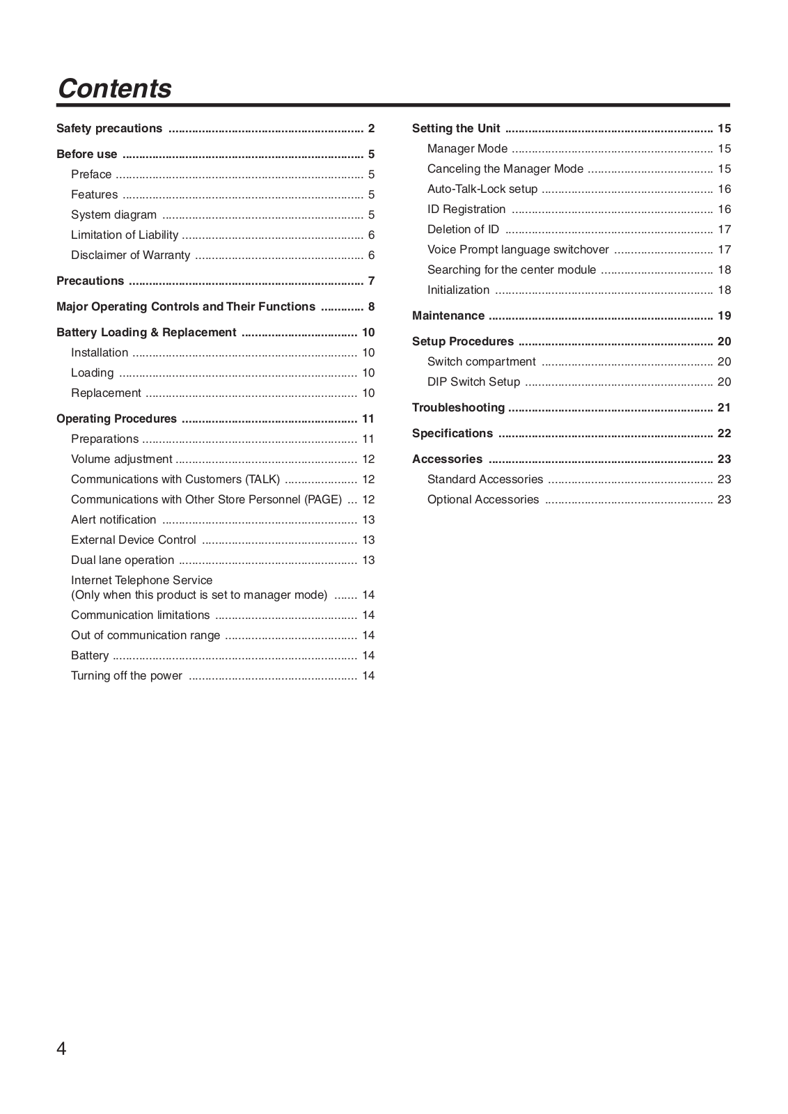
Table of contents
Loading...
Panasonic 9TAWX CH450 Users Manual
...
Panasonic Users Manual
Download
Specifications and Main Features
Frequently Asked Questions
User Manual
Download
Loading...
+
32
hidden pages
Unhide
You need points to download manuals.
1 point = 1 manual.
You can buy points or you can get point for every manual you upload.
Buy points
Upload your manuals
 Loading...