

Palfinger ILUK 33, ILUK 44, ILUK 55, ILUK 60 Owner's Manual
OWNER’S MANUAL
ILUK 33, 3300 lbs. Capacity
ILUK 44, 4400 lbs. Capacity
ILUK 55, 5500 lbs. Capacity
ILUK 60, 6000 lbs. Capacity
06/18

ILUK 33/44/55/60 Owner’s Manual
Rev.1.5 2
ILUK 33/44/55/60 Owner‘s Manual
Document Part Number: 90-0513-100 / 13-691_90-00_01-00
ECN-M01205, Rev. 1.5, 06-04-18
Copyright © 2018 Palfinger Liftgates LLC.
All rights reserved.
Information in this document is subject to change without notice.
Visit www.palfinger.com for up to date information and notifications.
If you received this product with damaged or missing parts,
contact Palfinger Liftgates at (888)-774-5844
Parts Order
liftgateparts@palfinger.com
15939 Piuma Ave.
Cerritos, CA 90703
Tel (888)-774-5844
Fax (562)-924-8318
572 Whitehead Road.
Trenton, NJ 08619
Tel (609)-587-4200
Fax (609)-587-4201

ILUK 33/44/55/60 Owner’s Manual
Rev.1.5 3
Table of Contents
1 Manual Updates ........................................................................................................................ 5
2 Important Notes ........................................................................................................................ 6
2.1 Attention ....................................................................................................................... 6
2.2 Important Notes ............................................................................................................ 6
2.3 General Information ...................................................................................................... 7
3 Safety Information .................................................................................................................... 9
4 General View of Liftgate ........................................................................................................... 11
4.1 ILUK 33/44/55/60 General Overview for Trailers ........................................................... 11
4.2 ILUK 33/44/55/60 General Overview for Trucks ............................................................ 12
5 Maximum Load and Placing of Load on Platform .................................................................. 13
6 Operation of Liftgate ................................................................................................................ 14
6.1 Operation Control Box................................................................................................... 14
6.2 Hand Held Remote Control ........................................................................................... 19
6.3 Wireless Hand Held Remote (Optional) ........................................................................ 19
6.4 Aluminum Platform Cart Stop Operation (Optional) ....................................................... 20
6.5 Foot Controls Operation (Optional) ............................................................................... 21
7 Preventive Maintenance and Quick Check ............................................................................. 22
7.1 Maintenance and Care .................................................................................................. 22
7.2 Lubrication ................................ ................................................................ .................... 23
7.3 Checking and Changing the Oil ..................................................................................... 24
7.4 Decal Placement and Inspection ................................................................................... 25
7.5 Quick Check List ........................................................................................................... 27
8 Troubleshooting ....................................................................................................................... 28
8.1.1 Liftgate will not power on. ................................................................................ 28
8.1.2 ON-OFF Switch is On, But All Functions are Dead .......................................... 31
8.1.3 Warning Lights ON, after ON-OFF Switch is Turned OFF ............................... 31
8.1.4 Platform Tilts Down Before it Reaches The Ground ........................................ 31
8.2 Electrical Wiring – Batteries – Truck/Trailer ................................................................... 32
8.3 Electrical System Codes ............................................................................................... 33
8.4 Connector Overview ..................................................................................................... 34
8.5 Cross Test on Single Pole Plug Charge System ........................................................... 35
8.6 Electrical Schematic ...................................................................................................... 36
8.7 Hydraulic Schematics.................................................................................................... 37

ILUK 33/44/55/60 Owner’s Manual
Rev.1.5 4
8.8 Functional Description of Hydrualics When Operating .................................................. 38
8.8.1 Slide Out Function ........................................................................................... 38
8.8.2 Lower Down and Auto Tilt Function ................................................................. 38
8.8.3 Level Out Activity ............................................................................................. 38
8.8.4 Lift Up Function ............................................................................................... 39
8.8.5 Slide In Function.............................................................................................. 39
8.9 ILUK Push Pull Valving ................................................................................................. 40
9 Needed Information for Ordering Spare Parts and Repairs ................................................... 42
9.1 Ordering Spare Parts .................................................................................................... 42
9.2 Repairs ......................................................................................................................... 42
10 Warranty .................................................................................................................................... 42
11 Contact Address ....................................................................................................................... 43
Company Information:
Company Name:
Advisor Name:
Vehicle Year Make & Model:
Liftgate Information:
Liftgate Serial Number:
Liftgate Model Number:
Date of Purchase:
Date of Installation:
Thank you for choosing Palfinger Liftgates.

ILUK 33/44/55/60 Owner’s Manual
Rev.1.5 5
1 Manual Updates
Revision
Description
v1.5
Reformatted manual to standard format.
Revised Liftgate Operiational Instructions.
Updated Electrical Schematic.

ILUK 33/44/55/60 Owner’s Manual
Rev.1.5 6
2 Important Notes
2.1 Attention
Before starting any operations of the liftgate, please read and understand this OWNER’S MANUAL. Its
intention is to act as a guide for the operation personal as well as to give help with preventive maintenance
but does not take place of unauthorized usage or repair by unqualified personnel.
Please contact your nearest PALFINGER Liftgates distributor or PALFINGER Liftgates in California or New
Jersey for assistance if you have questions regarding installation, operation or maintenance.
This owner’s manual applies to the following models: ILUK Under Slider 33, 44, 55 & 60
This is the safety alert symbol. It is used to alert you to potential personal injury hazards. Obey
all safety messages that follow this symbol to avoid possible injury.
2.2 Important Notes
This PALFINGER Liftgate is an electro-hydraulically driven lift gate, designed to be stored underneath the
truck or trailer for ultimate dock loading as well as offering up to seven foot platform.
The Hydraulic Power Unit (HPU) is easily accessible for service and exchange. The whole assembly slides
out and can be serviced at that point. To exchange the Hydraulic Power Unit (HPU), two hoses and the
battery cables need to be disconnected.
The platform folded in half is supported by two arms, linked with a torsion tube. The platform in a stored
position acts as the under ride guard. Lifting actions are carried out by hydraulic cylinders mounted on the
lift arms.
Two hydraulic tilt cylinders, one on each side of the lift arms are controlling the platform’s tilting action. This
enables the platform to maintain its position throughout the lift mode, regardless of the terrain.
The hydraulic cylinders are equipped with solenoid operated valves located at the port of each cylinder
which prevents the platform from lowering accidently unless the operator is activating the controls. This
system also enables you to store the lift gate without a separate platform latch.
The piston rods are treated against corrosion and also protected with plastic or rubber boots to protect from
road gravel and dirt. The HPU is equipped with a built-in pressure relief valve, which prevents overloading
when lifting or tilting up.

ILUK 33/44/55/60 Owner’s Manual
Rev.1.5 7
The valves do not prevent overloading of the platform when lowering or tilting down.
The electric supply is taken from the vehicle battery. If the vehicle battery is not sufficient or not existing (like
on trailer units), an auxiliary battery kit needs to be installed. The electric control power is protected via a 20
Amp fuse and an on-off switch. The switch has L.E.D. lights indicating when the control power is on. (Trailer
application have an on-off switch located in the lockable control box).
The liftgate is operated from an outside control box which is located on the curbside underneath the body. A
standard 2-button hand held remote control is also supplied with the lift. Foot controls are standard (except
for the ILUK 33), which enables the operator to handle the cargo and operate the lift by foot. A variety of
different products can be purchased with the PALFINGER Liftgate as well.
2.3 General Information
REMEMBER!
It is the fleet manager’s responsibility to educate the operator on the liftgate and its intended use. The
operator’s attention should be drawn to the permitted load limits and an understanding of the operation to
ensure the safety throughout the operation.
ONE-MAN OPERATION!
Never let an “outsider” operate the liftgate while you are handling the cargo.
A “misunderstanding” can result in serious personal injury.
In the interest of safety it is important that all operating personnel properly understand the functions
of the lift gate, possible hazards, dangers, the load limits and load positioning for that specific unit.
IMPORTANT NOTICE!
Before the operator uses the lift gate, they should be thoroughly familiar with the lift’s functions and
usage according to the following:
1. Improper operation of this lift can result in serious personal injury. Do not operate unless you have
been properly instructed, have read and are familiar with the operation instructions. If you do not
have a copy of the instructions please obtain them from your employer, distributor or lessor, as
appropriate, before you attempt to operate the lift.
2. Be certain the vehicle is properly and securely stopped before using the lift.

ILUK 33/44/55/60 Owner’s Manual
Rev.1.5 8
3. Always inspect this lift for maintenance or damage before using it. If there are signs of improper
maintenance, damage to vital parts or slippery platform surface, do not use the lift. Do not attempt
your own repairs unless you are specifically trained.
4. Do not overload. See the Rating Label on the unit for the rated load. Remember that this limit
applies to both raising and lowering operations.
5. Each load should be placed in a stable position as near as possible to the body of the truck/trailer.
6. Never stand in, move through or allow anyone else to stand in or move through the area in which the
lift operates, including that area in which a load might fall.
7. This is not a passenger lift. Do not ride the lift with unstable loads or in such a manner that a failure
would endanger you. The lift is not equipped with a back-up system to prevent falling cargo in the
event of a failure.
The maximum loads must be observed and followed!
IMPROPER USE
It is not permitted to use the tail lift:
As an elevating work platform
To push loads
To carry people (Only the operator may travel on the platform)
To clear snow
Please read through the operational and technical description of this PALFINGER Liftgate.
Thank you for choosing PALFINGER Liftgates.
ILUK 33/44/55/60 Owner’s Manual
Rev.1.5 9
3 Safety Information
This manual follows the Guidelines set forth in ANSI X535.4-2007 for alerting you to possible hazards and
their potential severity.
! DANGER indicates an imminently hazardous situation which, if not avoided, will result in death or serious
injury.
! WARNING indicates potentially hazardous situation which, if not avoided, could result in death or serious
injury.
! CAUTION indicates a potentially hazardous situation which, if not avoided, may result in minor or
moderate injury.
CAUTION without the safety alert symbol is used to address practices not related to personal injury.
(In this manual we use it to alert you to potentially hazardous situation which, if not avoided, may result in
property damage.)
NOTICE without the safety alert symbol is used to address practices not related to personal injury. (In this
manual we use it to alert you to special instructions, steps, or procedures.)

ILUK 33/44/55/60 Owner’s Manual
Rev.1.5 10
Improper operation of this liftgate may result in severe personal injury or death. DO NOT operate unless you
have been properly instructed, have read and are familiar with the procedures in this manual. We have
designed this manual to illustrate the steps needed for the basic operation of this ILUK liftgate. It also
provides safety information and simple preventive maintenance tips.
This manual is not intended for use as a repair or troubleshooting guide. Repairs should be performed by an
PALFINGER Liftgates Authorized Service Center.
This Manual has been designed for use in conjunction with the ILUK series liftgate only which is designed
for different capacities. You have different options to determine the type of your Liftgate:
1) Refer to the serial number tag on the Liftgate.
2) Ask your employer or lessor.
3) Call your PALFINGER Liftgates Authorized Service Center for assistance.
4) Call PALFINGER Liftgates for assistance in the USA at 888-774-5844. You can also contact
PALFINGER Liftgates by fax (562) 924-8318, or on the internet- www.PALFINGER.com
If you are facing any problems or are in need of repair, contact PALFINGER Liftgates for information
regarding experienced and trained Authorized Service Center in your area.
Replacement manuals are available to download at www.palfinger.com.
ILUK 33/44/55/60 Owner’s Manual
Rev.1.5 11
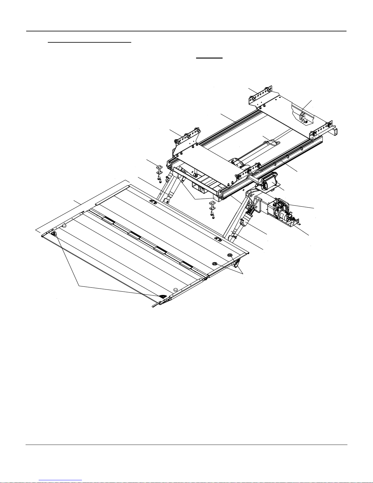
4 General View of Liftgate
4.1 ILUK 33/44/55/60 General Overview for Trailers
Hydraulic
Power
Unit
Platform
Control
Box
Wire
Management
Bar w/Rings
Liftarms
Tilt
Cylinders
Push Pull
Cylinders
Bracket
Rapid Mount
Bolt-On (RMB) Tray
(3",5",8" or 10"H)
Slider
Rails
Lift
Cylinders
Control
Board
(PCB)
Push/Pull
Cylinders
w/Tray
Platform
Bumpers
Rapid Mount
Bolt-On (RMB) Tray
(3",5",8" or 10"H)
Warning
Lights
Foot Controls
Slide
Rail
Stops
ILUK 33/44/55/60 Owner’s Manual
Rev.1.5 12
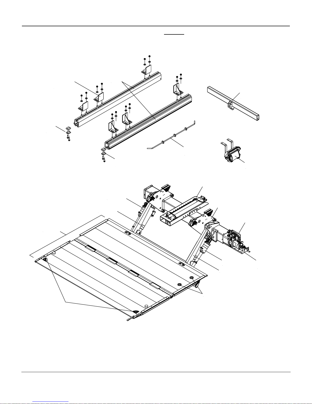
4.2 ILUK 33/44/55/60 General Overview for Trucks
Lift
Cylinders
Push/Pull
Cylinders
w/Tray
Tilt
Cylinders
Liftarms
Hydraulic
Power
Unit
Control
Board
(PCB)
Wire
Management
Bar w/Rings
Control Box
w/Mount Brackets
Slider
Rails
Push Pull
Cylinders
Bracket
Slide
Rail
Stops
Mounting
Brackets
w/Hardware
Mount
Plates
Tilt
Cylinders
Platform
Warning
Lights
Foot Controls
Slide
Rail
Stops
ILUK 33/44/55/60 Owner’s Manual
Rev.1.5 13
.
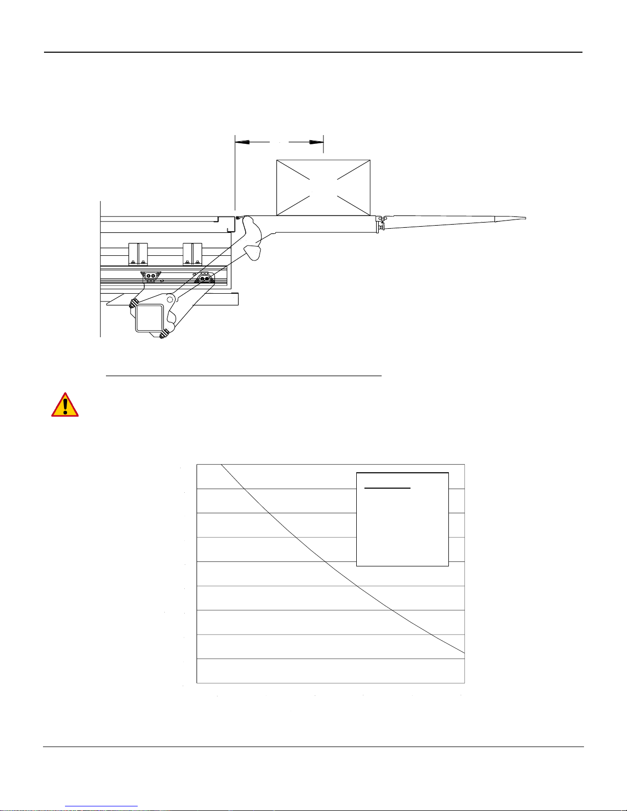
5 Maximum Load and Placing of Load on Platform
Every Palfinger Liftgate is rated up to a maximum load. The point of maximum load is rated at a defined
distance. The center point of maximum load is at 24” from the rear of the bed extension out to the platform.
24"
Load
By increasing this distance the maximum load of the liftgate is decreasing.
An overview about the rating depending, on the distance from the end of the platform is shown in the
following load diagram.
24
36 48
60
72
84
10
20
30
40
50
60
70
80
90
100
Distance From Body (inches)
Capacity (%)
Capacity:
100% at 24”
80% at 36”
60% at 48”
45% at 60”
 Loading...