

Palfinger ILP 33, ILP 25 Owner's Manual
OWNER’S MANUAL
ILP 25, 2500 lbs. Capacity
ILP 33, 3300 lbs. Capacity
02/19

ILP 25/33 Owner’s Manual
Rev.1.4 2
ILP 25/33 Owner‘s Manual
Document Part Number: 90-0116-001 / 16-684_90-00_00-01
ECN-M1301, Rev. 1.4, 02-01-19
Copyright © 2019 Palfinger Liftgates LLC.
All rights reserved.
Information in this document is subject to change without notice.
Visit www.palfinger.com for up to date information and notifications.
If you received this product with damaged or missing parts,
contact Palfinger Liftgates at (888)-774-5844
15939 Piuma Ave.
Cerritos, CA 90703
Tel (888) 774-5844
Fax (562) 924-8318
572 Whitehead Road.
Trenton, NJ 08619
Tel (609) 587-4200
Fax (609) 587-4201

ILP 25/33 Owner’s Manual
Rev.1.4 3
Table of Contents
1 Manual Updates ........................................................................................................................ 5
2 Safety Information .................................................................................................................... 6
2.1 General Safety .............................................................................................................. 7
3 Important Information .............................................................................................................. 8
3.1 Improper Useage .......................................................................................................... 9
4 General View of Liftgate ........................................................................................................... 10
4.1 ILP Liftgate Overview .................................................................................................... 10
5 Maximum Load and Placing of Load on Platform .................................................................. 11
6 Operation of Liftgate ................................................................................................................ 12
6.1 Operation by Toggle Switch/Hand Held Remote Control ............................................... 12
6.2 Hand Held Remote Control (Optional) ........................................................................... 14
6.3 Wireless Hand Held Remote (Optional) ........................................................................ 14
6.4 Cart Stops Operation (Optional) .................................................................................... 15
7 Preventive Maintenance and Quick Check ............................................................................. 17
7.1 Maintenance and Care .................................................................................................. 17
7.2 Lubrication ................................ ................................................................ .................... 18
7.3 Checking and Changing the Oil ..................................................................................... 19
7.3.1 Recommended Hydraulic Fluids Table ............................................................ 20
7.4 Decal Placement and Inspection ................................................................................... 21
7.5 Quick Check List ................................................................ ........................................... 23
8 Troubleshooting ....................................................................................................................... 23
8.1 Liftgate will not power on. .............................................................................................. 24
8.2 Liftgate does not Lower Down ....................................................................................... 26
8.3 Liftgate does not Lift Up ................................................................................................ 27
8.4 Electrical Wiring – Batteries – Truck/Trailer ................................................................... 28
8.5 Cross Test on Single Pole Plug Charge System ........................................................... 29
8.6 Electrical Schematic (Gravity Down ) ............................................................................ 30
8.7 Electrical Schematic (Power Down ) ............................................................................. 31
8.8 Hydraulic Schematics (Gravity Down) ........................................................................... 32
8.9 Hydraulic Schematics (Power Down) ............................................................................ 33
9 Needed Information for Ordering Spare Parts and Repairs ................................................... 34
9.1 Ordering Spare Parts .................................................................................................... 34
9.2 Repairs ......................................................................................................................... 34

ILP 25/33 Owner’s Manual
Rev.1.4 4
10 Warranty .................................................................................................................................... 34
11 Contact Address ....................................................................................................................... 35
Company Information:
Company Name:
Advisor Name:
Vehicle Year Make & Model:
Liftgate Information:
Liftgate Serial Number:
Liftgate Model Number:
Date of Purchase:
Date of Installation:
Thank you for choosing Palfinger Liftgates.

ILP 25/33 Owner’s Manual
Rev.1.4 5
1 Manual Updates
Revision
Description
v1.1
Changed product name from PLP to ILP.
v1.2
Revised Sections 13.9, 13-10: Toggle switch wire colors updated.
v1.3
Updated Sections 8.6 & 8.7
v1.4
Updated pictorials throughout manual to match actual product.
ILP 25/33 Owner’s Manual
Rev.1.4 6
2 Safety Information
This manual follows the Guidelines set forth in ANSI X535.4-2007 for alerting you to possible hazards and
their potential severity.
! DANGER indicates an imminently hazardous situation which, if not avoided, will result in death or serious
injury.
! WARNING indicates potentially hazardous situation which, if not avoided, could result in death or serious
injury.
! CAUTION indicates a potentially hazardous situation which, if not avoided, may result in minor or
moderate injury.
CAUTION without the safety alert symbol is used to address practices not related to personal injury.
(In this manual we use it to alert you to potentially hazardous situation which, if not avoided, may result in
property damage.)
NOTICE without the safety alert symbol is used to address practices not related to personal injury. (In this
manual we use it to alert you to special instructions, steps, or procedures.)

ILP 25/33 Owner’s Manual
Rev.1.4 7
2.1 General Safety
REMEMBER!
It is the fleet manager’s responsibility to educate the operator on the liftgate and its intended use. The
operator’s attention should be drawn to the permitted load limits and an understanding of the operation to
ensure safety throughout the operation.
ONE-MAN OPERATION!
Never let an “outsider” operate the liftgate while you are handling the cargo. A “misunderstanding” can
result in serious personal injury or even death.
In the interest of safety it is important that all operating personnel properly understand the functions
of the liftgate, possible hazards, dangers, the load limits and load positioning for that specific unit.
IMPORTANT NOTICE!
Before the operator uses the liftgate, they should be thoroughly familiar with the lift’s functions and
usage according to the following:
1. Improper operation of this lift can result in serious personal injury. Do not operate unless you have
been properly instructed, have read and are familiar with the operation instructions. If you do not
have a copy of the instructions please obtain them from your employer, distributor or lessor, as
appropriate, before you attempt to operate the lift.
2. Be certain the vehicle is properly and securely stopped before using the lift.
3. Always maintain the liftgate and inspect it for damage before usage. If there are signs of improper
maintenance, damage to vital parts, or slippery platform surface, do not use the lift. Do not attempt
your own repairs unless you are specifically trained.
4. Do not overload. See the Rating Label on the unit for the rated load. Remember that this limit
applies to both raising and lowering operations.
5. Each load should be placed in a stable position as near as possible to the body of the truck/trailer.
6. Never stand in, move through or allow anyone else to stand in or move through the area in which the
lift operates, including that area in which a load might fall.
7. This is not a passenger lift. Do not ride the lift with unstable loads or in such a manner that a failure
would endanger you. The lift is not equipped with a back-up system to prevent falling cargo in the
event of a failure.

ILP 25/33 Owner’s Manual
Rev.1.4 8
Improper operation of this liftgate may result in severe personal injury or death. DO NOT operate unless
you have been properly instructed, have read and are familiar with the procedures in this manual. We have
designed this manual to illustrate the steps needed for the basic operation of this ILR+ liftgate. It also
provides safety information and simple preventive maintenance tips.
3 Important Information
Before Getting Started
“READ FIRST”
Before starting any operations of the liftgate, please read and understand this Owner’s Manual. The
intention of this manual is to provide the user a guide for the operation as well as preventive
maintenance. Do not attempt to modify or repair the liftgate unless performed by qualified
personnel. Please contact your nearest Palfinger Liftgates distributor or Palfinger Liftgates in
California or New Jersey for assistance if you have any questions regarding installation, operation
or maintenance at 888-774-5844.
This owner’s manual applies to the following models: ILP 25 / 33
Important notes
The electric supply is taken from the vehicle battery. If the vehicle battery is not sufficient, an auxiliary
battery kit needs to be installed. The electric control power is secured via a 15-Amp fuse and an on-off
switch located inside the cab.
Trailer applications have an on/off switch near the rear curb side corner post.
The liftgate is operated from a standard toggle switch. A hand held remote control is optional with up and
down functions. A variety of different control options can be purchased with the Palfinger Liftgates product.
The valves do not prevent overloading of the platform when lowering or tilting down.
This manual is not intended for use as a repair or troubleshooting guide. Repairs should be
performed by a Palfinger Liftgates Authorized Service Center.
This Manual has been designed for use in conjunction with the ILP series liftgates only which are designed
for different capacities. There are four options available to determine the model and serial number of the
installed liftgate:
ILP 25/33 Owner’s Manual
Rev.1.4 9
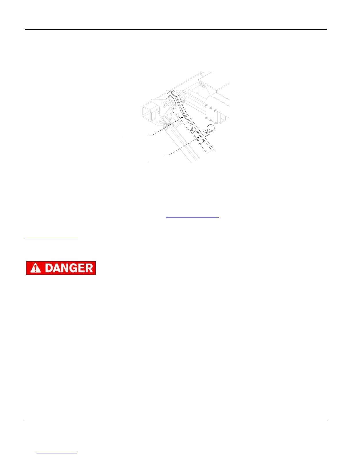
1) Refer to the serial number tag on the liftgate, the tag can be found on the street side liftarm, as shown in
Fig.1.
Serial
Number
Tag
Liftarm
(Driver Side)
2) Ask your employer or lessor;
3) Call your Palfinger Liftgates Authorized Service Center for assistance.
4) Call Palfinger Liftgates for assistance in the USA at 888-774-5844. You can also contact Palfinger
Liftgates by fax (562) 924-8318 or on the internet- www.palfinger.com
For technical support, contact Palfinger Liftgates or an authorized Palfinger service center.
www.palfinger.com
3.1 Improper Useage
Some examples of improper use of the liftgate may include, but are not limited to:
Using the liftgate as an elevating work platform.
Using the liftgate to push, pull, or tow loads or other objects.
Using the liftgate to carry people (Only the operator may travel on the platform).
Using the liftgate to clear snow.
Trying to use the liftgate as a “launching pad”.
Using force of the hydraulic system to bend, shear, or break objects.
Driving a forklift over the liftgate.
Driving the truck or trailer with the platform open.
Plowing with the platform.
Fig.1
ILP 25/33 Owner’s Manual
Rev.1.4 10
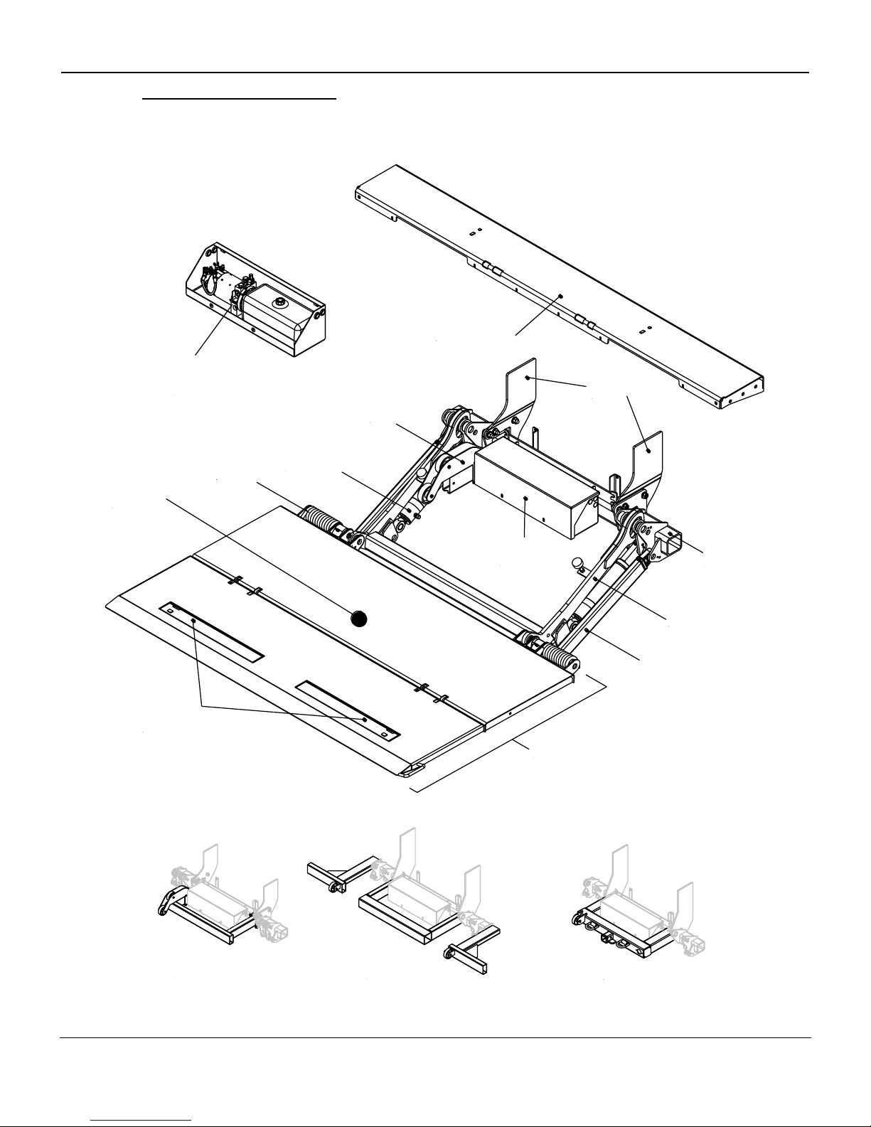
4 General View of Liftgate
4.1 ILP Liftgate Overview
Load Center
of Gravity
DOT Bumper
Hitch Bumper
Center Bumper
Hydraulic
Power Unit
Liftarm
Parallel Arm
Platform
Cart Stops
(Optional)
Single Action or
Double Action
Lift Cylinders
Springs*
Hydraulic
Power
Unit
Platform
Roll Off
Wheels
Bolt-On
Mount Plates
Mount
Frame
Bed Extension
*No spring installed on left side for 42“ and 48“ aluminum platforms only.
ILP 25/33 Owner’s Manual
Rev.1.4 11
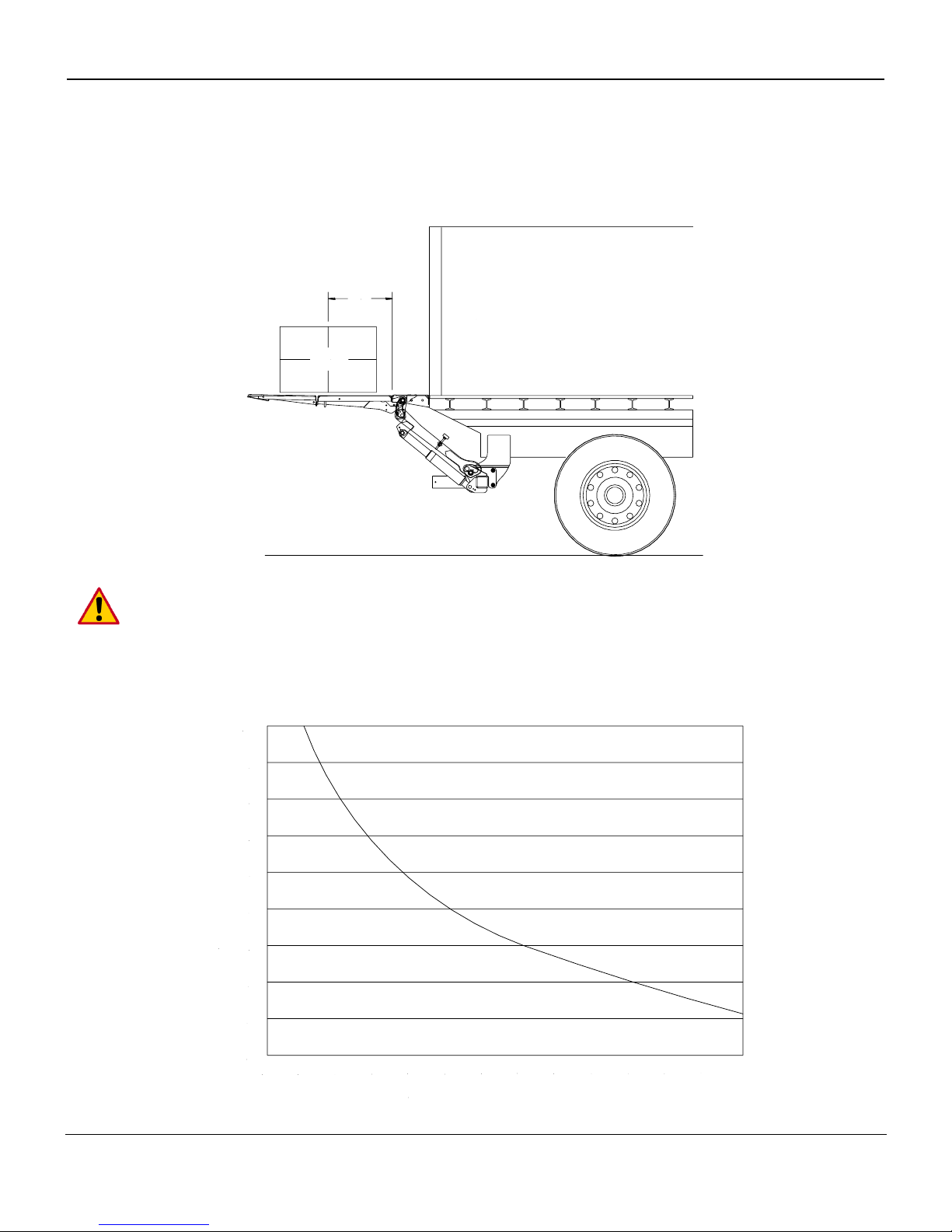
5 Maximum Load and Placing of Load on Platform
Every Palfinger Liftgate is rated up to a maximum load. The point of maximum load is rated at a defined
distance. The center point of maximum load is at 24” from the rear of the bed extension out to the platform,
Fig.2.
24"
Vehicle
Load
By increasing this distance the maximum load of the liftgate is decreasing.
An overview about the rating depending, on the distance from the end of the platform is shown in the
following load diagram.
18
24
30
36
42
48
54
60
66
72
78
84
90
10
20
30
40
50
60
70
80
90
100
Distance From Body (inches)
Capacity (%)
Fig.2
 Loading...