

Palfinger ILF 33, ILF 55, ILF 44 Installation Manual
ILF 33 – 3300 lbs. Capacity
ILF 44 – 4400 lbs. Capacity
ILF 55 – 5500 lbs. Capacity
INSTALLATION MANUAL
& CHECK-OFF SHEET
09/16

ILF 33/44/55 Installation Manual
Palfinger Liftgates ILF 33/44/55 Installation Manual
Document Part Number: 90-0815-000 / 15-696_90-00_00-00
ECN-M0819, Rev. 1.1, 09-14-16
Copyright © 2016 Palfinger Liftgates LLC.
All rights reserved.
Information in this document is subject to change without notice.
Visit www.palfinger.com for up to date information and notifications.
If you received this product with damaged or missing parts,
contact Palfinger Liftgates at (888)-774-5844
Parts Order
liftgateparts@palfinger.com
Technical Support
technicalapplications@palfinger.com
PALFINGER Liftgates, LLC.
15939 Piuma Ave.
Cerritos, CA 90703
Tel (888)-774-5844
Fax (562)-924-8318
PALFINGER Liftgates, LLC.
572 Whitehead Road.
Trenton, NJ 08619
Tel (609)-587-4200
Fax (609)-587-4201
Rev 1.1 2

ILF 33/44/55 Installation Manual
Table of Contents
1 Manual Updates for v1.1 .......................................................................................................... 5
2 Safety Information ................................ ................................................................ .................... 6
3 Important Information .............................................................................................................. 7
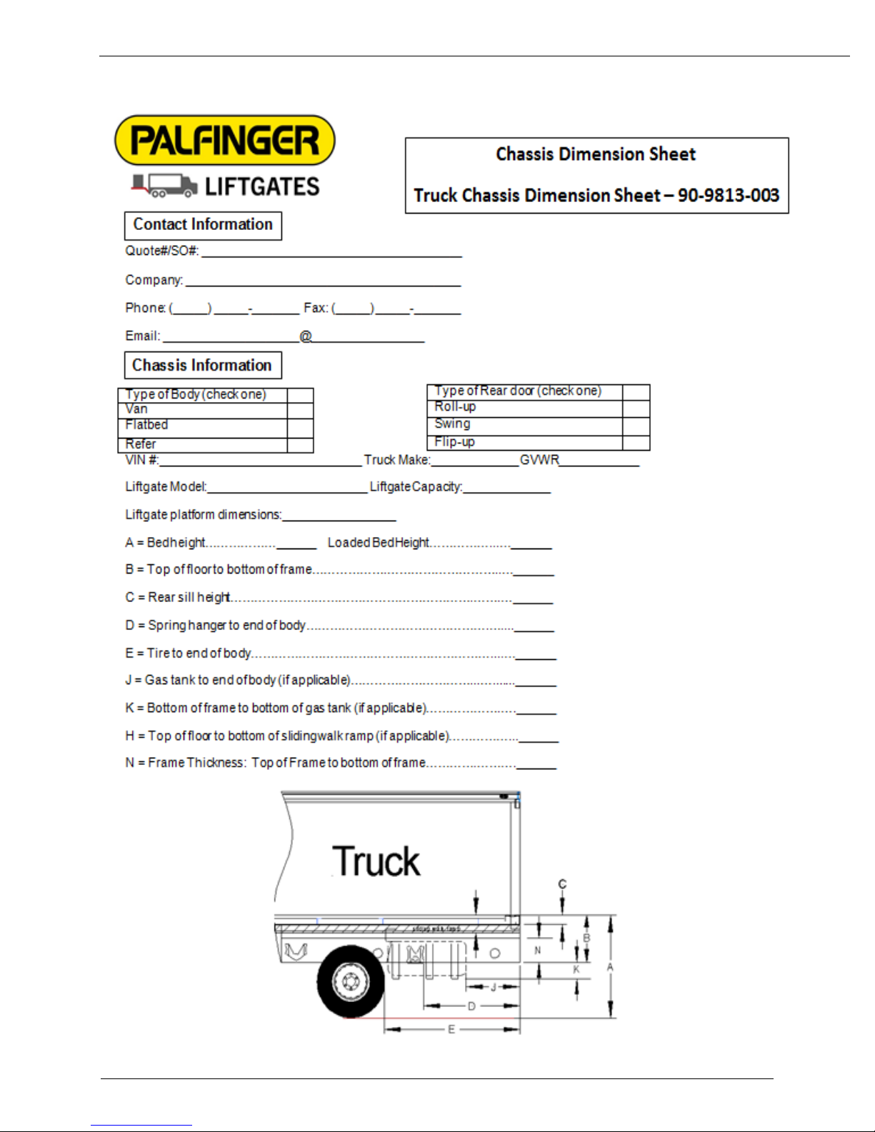
Important Dimensions ................................................................................................... 9 3.1
Recommended Tools .................................................................................................... 9 3.2
4 Dimension Sheet ...................................................................................................................... 10
5 General Overview of ILF Liftgate ............................................................................................. 12
6 Chassis and Body Preparation ................................................................................................ 14
Installation Dimensions ................................................................................................. 14 6.1
Chassis Cut Out ILF 33 ................................................................................................. 15 6.2
6.2.1 Installation Dimensions ILF 44 and ILF 55 ....................................................... 16
Chassis Cut Out ILF 44/55 ................................ ............................................................ 17 6.3
Frame Cap ................................................................ .................................................... 18 6.4
Bed Extension Installation ............................................................................................. 20 6.5
Dock Bumper Installation – Weld On (Optional) ............................................................ 22 6.6
7 Liftgate Installation (Truck) ...................................................................................................... 24
Installation ..................................................................................................................... 24 7.1
8 Liftgate Installation (Trailer) ..................................................................................................... 30
Installation ..................................................................................................................... 30 8.1
Operation of B-15 Sensor ............................................................................................. 34 8.2
Operation of B-13 Sensor ............................................................................................. 35 8.3
9 Electrical Installation ................................................................................................................ 36
Wire Crimping ............................................................................................................... 37 9.1
Circuit Breaker Installation ............................................................................................ 38 9.2
Cable Routing ............................................................................................................... 39 9.3
Main Power Connections .............................................................................................. 40 9.4
On-Off Switch Installation (Truck Application) ............................................................... 41 9.5
On-Off Switch Installation (Trailer Application) .............................................................. 42 9.6
Remote Hand Control Installation ................................................................................. 44 9.7
Foot Control Installation (Optional) ................................................................................ 46 9.8
Electrical Schematic ...................................................................................................... 48 9.9
Control Board Codes .................................................................................................... 49 9.10
Rev 1.1 3

ILF 33/44/55 Installation Manual
10 Lubrication ................................................................................................................................ 50
11 Hydraulic Schematic ................................................................................................................ 51
12 Decal Placement and Inspection ................................ ............................................................. 52
13 Final Inspection Check List ................................ ..................................................................... 54
Company Information:
Company Name:
Advisor Name:
Trailer Year Make & Model:
Liftgate Information:
Liftgate Serial Number:
Liftgate Model Number:
Date of Purchase:
Date of Installation:
Rev 1.1 4

ILF 33/44/55 Installation Manual
1 Manual Updates for v1.1
Updated Section 7.8: Foot control installation
Updated Section 8.2: Decal placement
Rev 1.1 5
ILF 33/44/55 Installation Manual
2 Safety Information
This manual follows the guidelines set forth in “ANSI Z535.4-2007” for alerting you to possible
hazards and their potential severity.
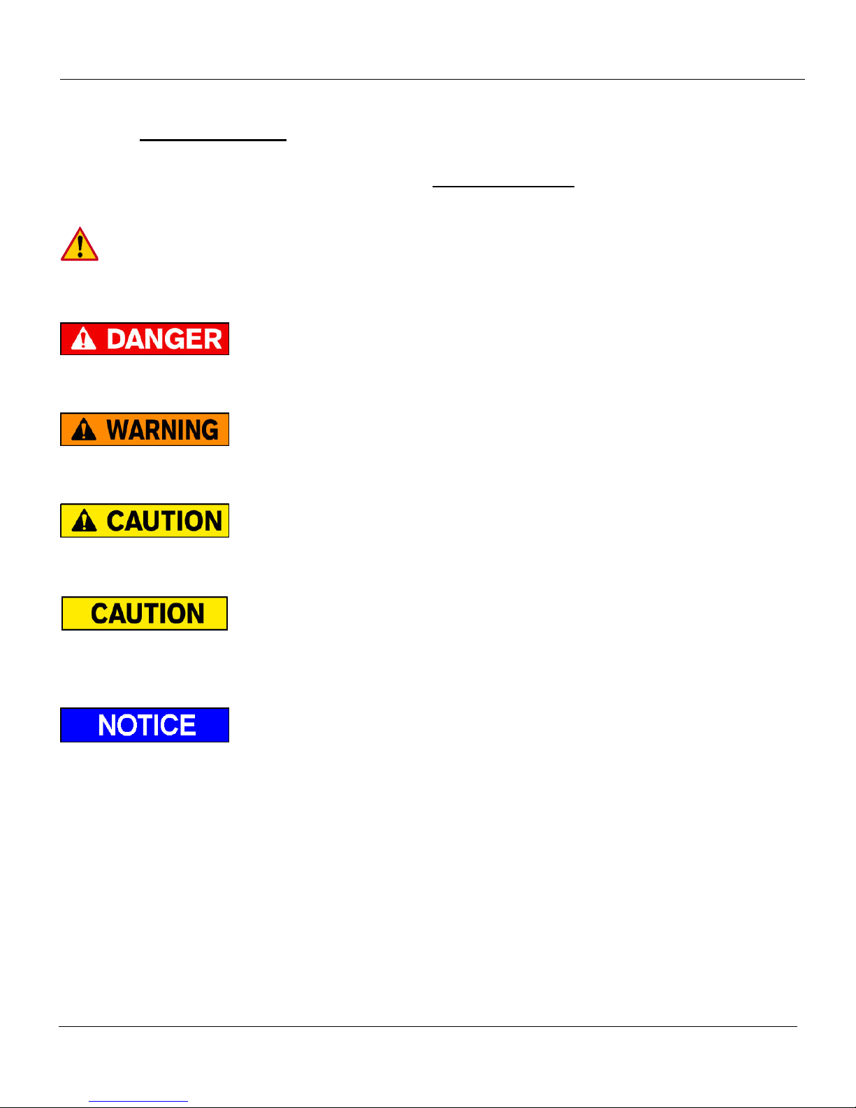
This is the safety alert symbol. It is used to alert you to potential personal injury hazards.
Obey all safety messages that follow this symbol to avoid possible injury or death.
! DANGER indicates an imminently hazardous situation which, if not avoided, will result in death or
serious injury.
! WARNING indicates potentially hazardous situation which, if not avoided, could result in death or
serious injury.
! CAUTION indicates a potentially hazardous situation which, if not avoided, may result minor or
moderate injury.
CAUTION without the safety alert symbol is used to address practices not related to personal
injury. (In this manual we use it to alert you to potentially hazardous situation which, if not avoided,
may result in property damage.)
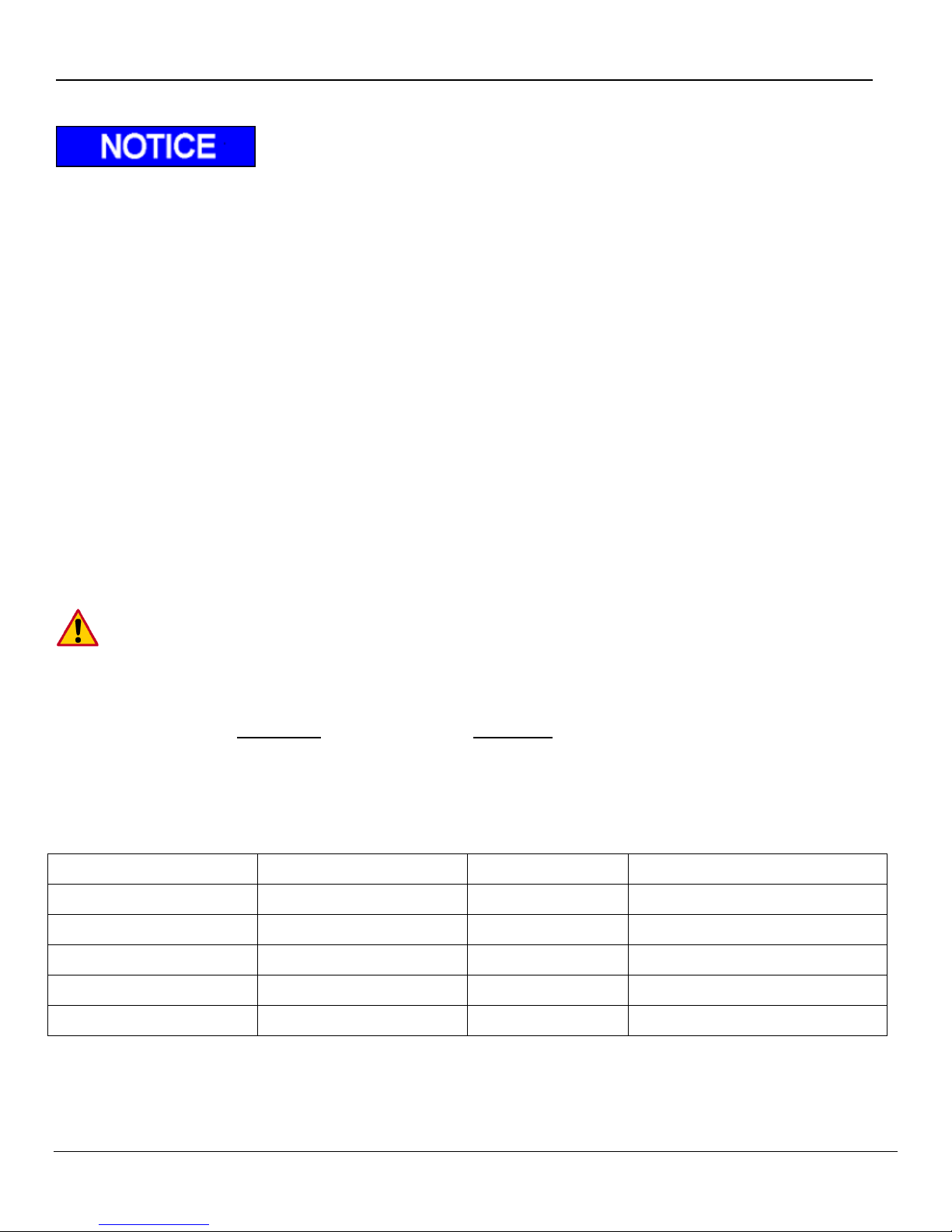
NOTICE without the safety alert symbol is used to address practices not related to personal injury.
(In this manual we use it to alert you to special instructions, steps, or procedures.)
Rev 1.1 6

ILF 33/44/55 Installation Manual
3 Important Information
Before Getting Started
“READ FIRST”
The ILF liftgate is a heavy duty industrial hydraulic lifting device. Performance and reliability
are closely related to proper installation, battery cable connections, and grounding. All
grounding surfaces MUST be cleaned, prepped, and sealed per this manual. “Cut to size”
cables MUST be properly crimped and sealed as factory supplied. All connections MUST be
dressed with dielectric grease or equivalent sealer.
Review lift gate invoice, packing slip, and installation drawing to assure delivery of correct gate
and complete delivery of accessories and optional equipment.
Read and understand the “Installation Manual” and “Owner’s Manual” in their entirety before
starting your Installation.
Refer to your truck manufacturer’s instructions before adding any auxiliary equipment. Installer is
responsible for compliance with this manual, OEM and FMVSS requirements.
All welding should be performed by qualified personnel per AWS standards.
Always Ground closest to your welding point to prevent arcing through moving parts or electrical
parts.
Contact PALFINGER Liftgates for Special Installations not covered in this Installation Manual.
Do not paint cylinder shafts or nylon bearings (Use non-chlorinated brake cleaner to remove over
spray)
Final Check-Off-Sheet at rear of this manual MUST be filled out and kept in your records for
future reference.
Refer to owner’s manual for Operation and Maintenance information.
Check the battery voltage before installation. Flooded lead acid batteries should measure 12.6V
and AGM batteries should measure 12.8V. If batteries are not at these voltages, fully charge
before installation
Rev 1.1 7

ILF 33/44/55 Installation Manual
Improper operation of this liftgate may result in severe personal injury or death. DO NOT
operate unless you have been properly instructed, have read and are familiar with the
procedures in this manual. This manual has been designed to illustrate the steps needed for
the basic installation of the ILF liftgate. It also provides safety information and simple
preventive maintenance tips.
This manual is not intended for use as a repair or troubleshooting guide. Repairs should be
performed by a Palfinger Liftgates Authorized Service Center.
This manual has been designed for use in conjunction with the ILF series liftgates only which is
designed for different capacities. There are four options to determine the model and serial number of
the installed liftgate:
1) Refer to the serial number tag on the liftgate (Top of Mount Frame).
2) Ask your employer or lessor;
3) Call your PALFINGER Liftgates Authorized Service Center for assistance.
4) Call PALFINGER Liftgates for assistance in the USA at 888-774-5844. You can also contact
PALFINGER Liftgates by fax (562) 924-8318 or on the internet at www.palfinger.com
For technical support, contact PALFINGER Liftgates or an authorized PALFINGER service center.
www.palfinger.com
Rev 1.1 8
ILF 33/44/55 Installation Manual
Metric Wrench Set
Basic Screwdrivers
Pliers
Wire Crimp Pliers
Digital Multimeter
Snap Ring Pliers
Hammer
Metric Allen Set 1.5mm-10mm
½” Impact & Sockets
Sm. Metric Socket Set
Assorted Drill Bits
Floor Jack or Equiv.
Sm. To Med. Bottle Jack
Forklift or O/H Crane
Hand Held Grinder
Paint Gun
Cutting Torch or Equiv.
3/8 Drill Motor
Pry Bar
Heat Gun or Equiv.
Min. 250 Amp Welder
Important Dimensions 3.1
Minimum Bed Height dimensions are ALWAYS MAXIMUM LOADED TRUCK.
Maximum Bed Height dimensions are ALWAYS DRY UNLOADED TRUCK.
Installing a gate at or close to minimum bed height normally results in a gate that will NOT open
and close from stored position if the minimum floor height is exceeded when truck is loaded.
Ensure trailer body does not interfere with installation or operation of the ILF liftgate series.
It is not recommended to cut, torch, or remove support materials from trailer. Removing gussets,
stiffeners, light rings, or other such support structures may VOID your trailer warranty.
Call technical support before starting the installation if any questions or concerns arise on
mounting dimensions or procedures.
Mounting Notes:
Read and clearly understand manual BEFORE beginning ANY work.
The basic rule of PALFINGER Liftgates‟s ILF installation is to lift mount frame
to achieve MAXIMUM ground clearance WITHOUT exceeding Min “F” dimension.
Recommended Tools 3.2
Rev 1.1 9
ILF 33-44-55 Installation Manual
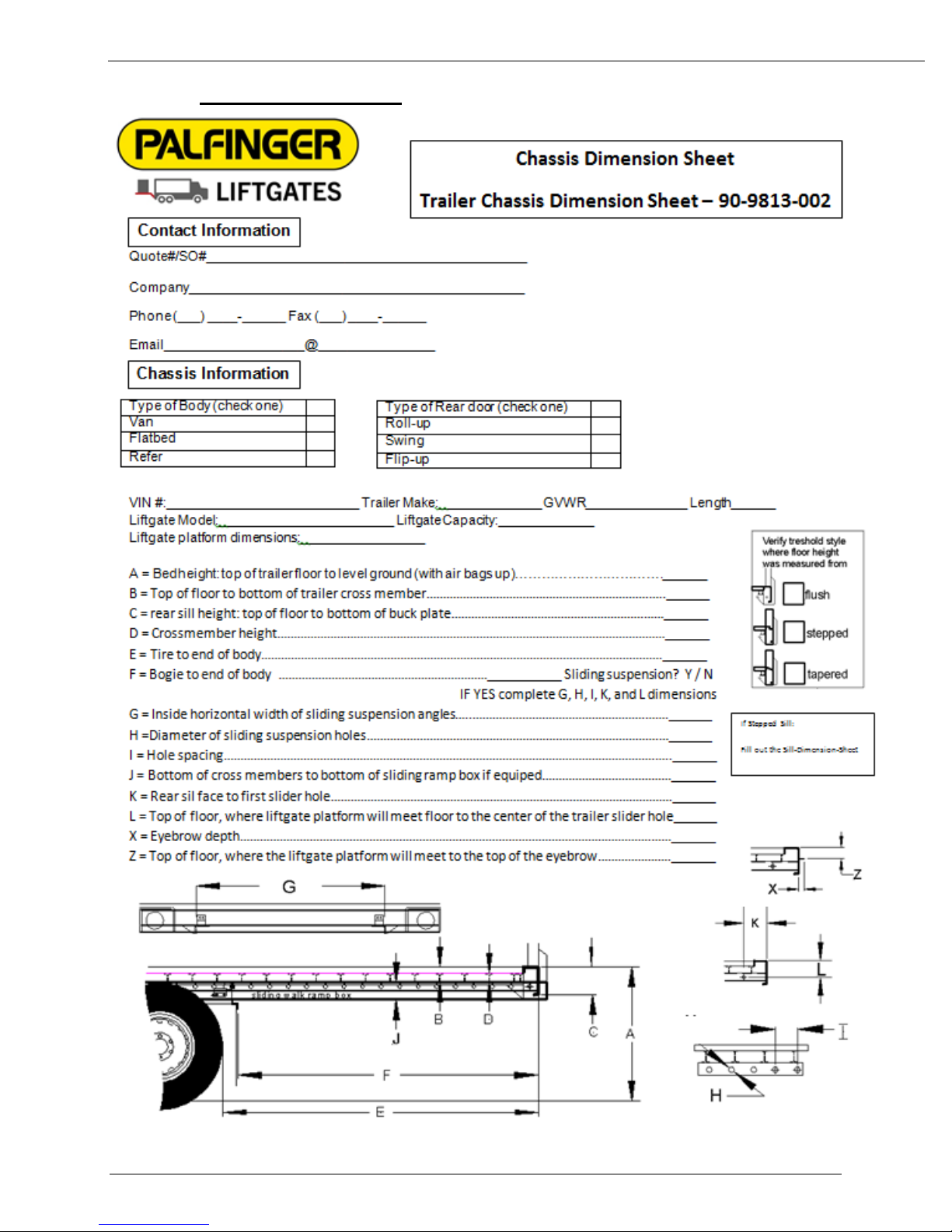
4 Dimension Sheet
Rev 1.1 10
ILF 33-44-55 Installation Manual
Rev 1.1 11
ILF 33/44/55 Installation Manual
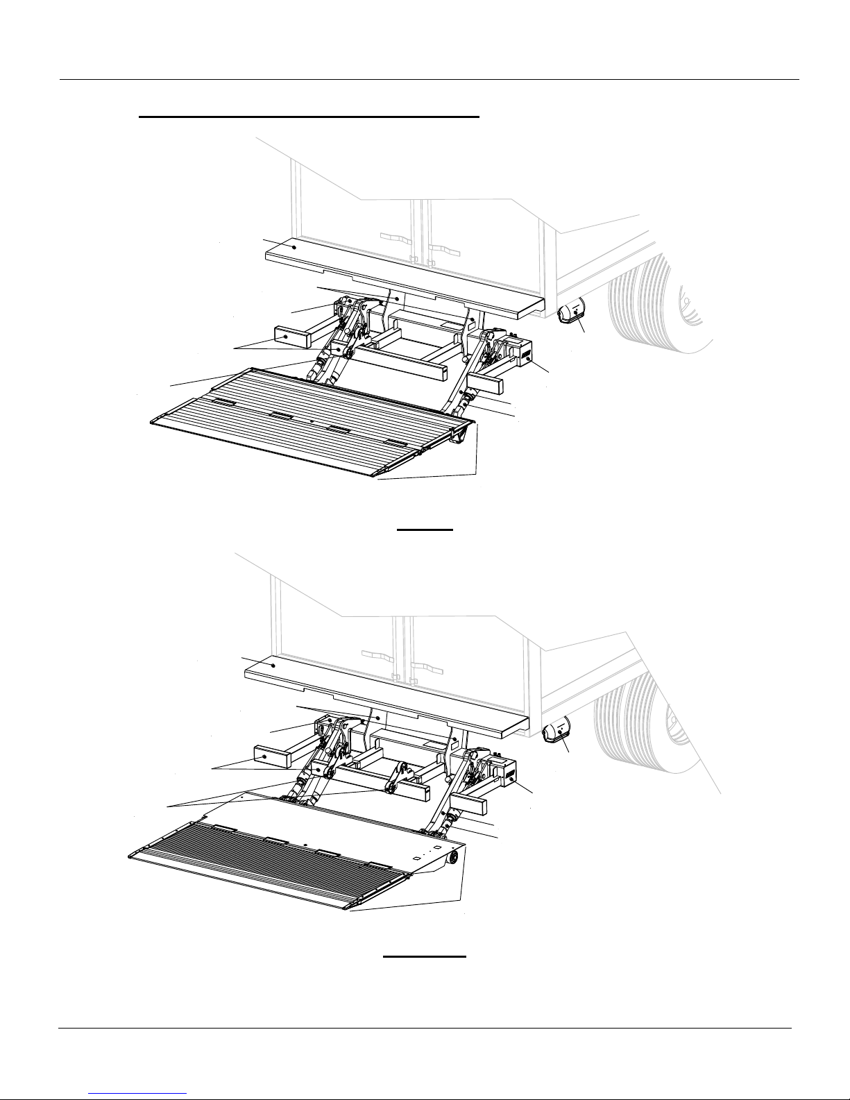
Bumper
Bed
Extension
Mount Frame
Tilt Arm
Lift Arm
Control
Box
Hydraulic
Power Unit
Aluminum
Platform
Mount Plates
Parting
Wheel
Bumper
Bed
Extension
Mount Frame
Tilt Arm
Lift Arm
Control
Box
Hydraulic
Power Unit
Steel/Aluminum
Platform
Mount Plates
Parting
Wheels
5 General Overview of ILF Liftgate
ILF 33
ILF 44/55
Rev 1.1 12
ILF 33/44/55 Installation Manual
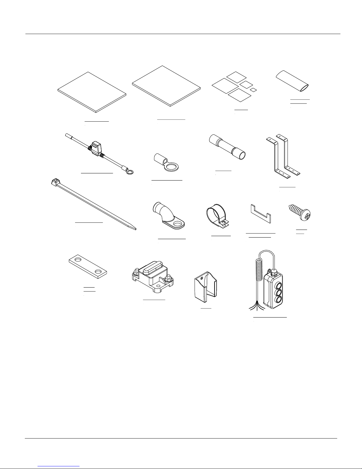
In-Line Fuse, 20 Amp
1 pcs
Heat Shrink,
ø1/2" x 3"L
1 pc
Copper
Bus Bar
1 pc
Circuit Breaker
1 pc
Owner's Manual
1 pc
Installation Manual
1 pc
Battery Lug, 5/16"
1 pc
Decal Kit
15 pcs
8" Nylon Cable Tie
12 pcs
Ring Connector, 3/8"
1 pc
Butt Splice
1 pcs
Holster
1 pc
3-Button Hand Control
1 pc
Cable Clamp
5 pcs
Screws
2 pcs
Mount Plate Gusset
Only for ILF 55
2 pcs
Z-Brackets
2 pcs
Boxed Items Included with Liftgate for Installation
Rev 1.1 13
ILF 33/44/55 Installation Manual
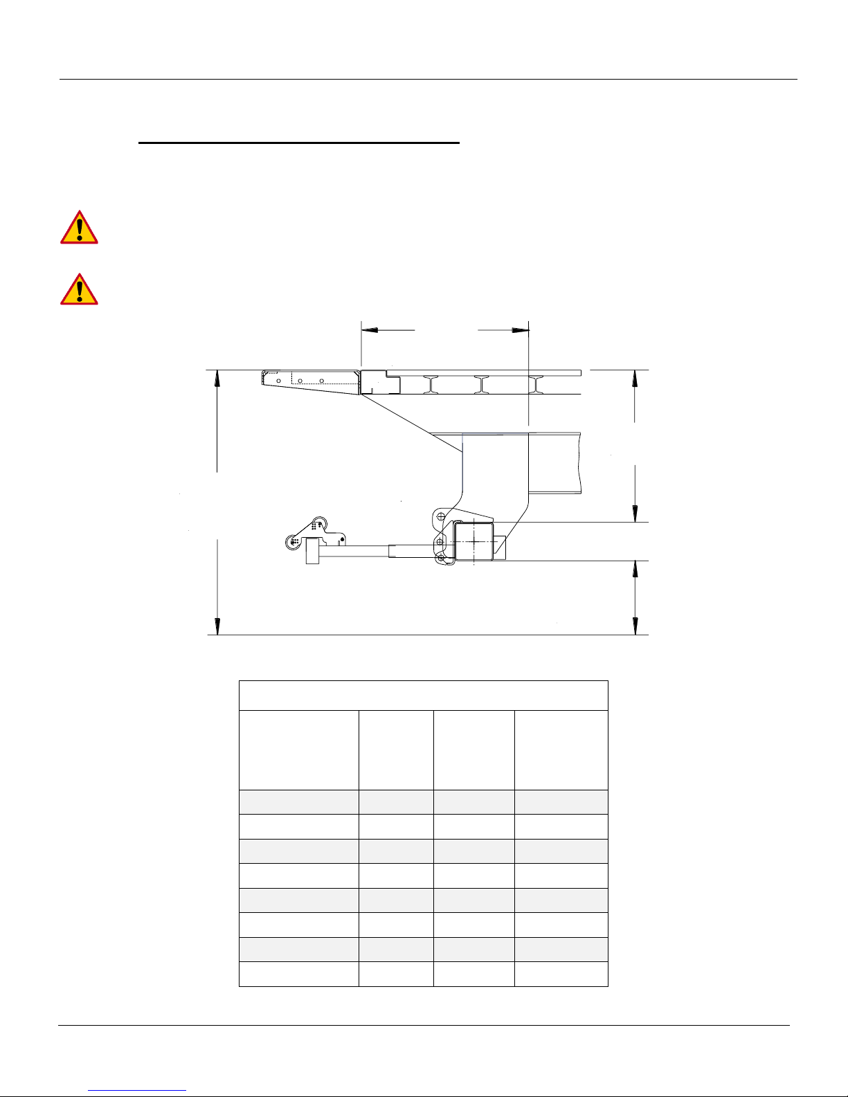
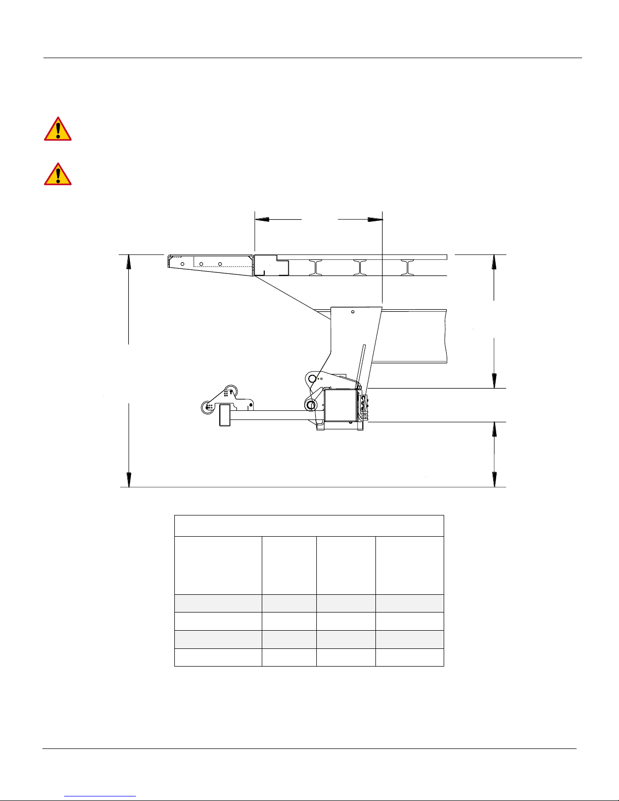
"K"
Mount Clearance
(Reference)
"F" Dim.
Bed Height
Max. 62"
Min. 46"
"G"
Ground
Clearance
Sill
ILF 33 Mounting Dimension Table
Bed Height
(Loaded)
F
Dim.
G
Dim.
K
Dim.
(Ref.)
62“
33“
20“
29“
58“
32“
19“
30“
56“
31“
18“
31“
54“
30“
17“
31.5“
52“
29“
16“
32.5“
50“
28“
15“
33“
48“
27“
14“
34“
46“
26“
13“
35“
6 Chassis and Body Preparation
Installation Dimensions 6.1
IMPORTANT:
Always use the smallest F-dim possible for best ground clearance
(Don‟t exceed max. ground clearance)
Minimum bed height is when truck/trailer is loaded to MAX GVW
Rev 1.1 14

ILF 33/44/55 Installation Manual
22"
12"
18"
13"
21"
12"
17"
13"
Assuming 26" F-Dimension
Assuming 27" F-Dimension
Assuming 28" F-Dimension
Cut
Assuming 29" F-Dimension
Assuming 30" F-Dimension
Assuming 31" F-Dimension
Assuming 32" F-Dimension
Assuming 33" F-Dimension
Cut
Cut
Cut
Spacer
Bed Extension
Sill
(Over 4"
in Height)
Chassis
Cut
Fig. 1
Fig. 2
Chassis Cut Out ILF 33 6.2
These dimensions are starting points due to variation of installations. The final dimensions
may vary depending on actual installation F-Dim.
1. Determine the correct frame cut out according to your specific bed height. With long overhangs it is
even more important to maintain min F = Max ground clearance, Fig. 1.
2. If the vehicles sill measures more than 4” in height, add a spacer to the rear of the vehicle, Fig. 2.
The spacer will shift the bed extension back allowing the platform to clear the bottom of the sill when
it is in stored position. Reference cutout dimensions from Step 1 to determine the chassis cutout.
Rev 1.1 15
ILF 33/44/55 Installation Manual
"K"
Mount Clearance
(Reference)
"F" Dim.
Bed Height
Max. 55"
Min. 50"
"G"
Ground
Clearance
Sill
ILF 44/55 Mounting Dimension Table
Bed Height
(Loaded)
F
Dim.
G
Dim.
K
Dim.
(Ref.)
55“
28“
19.5“
26“
54“-53“
27“
19“
27“
52“-51“
26“
18“
28“
50“
25“
17“
29“
6.2.1 Installation Dimensions ILF 44 and ILF 55
IMPORTANT:
Always use the smallest F-dim possible for best ground clearance
(Don‟t exceed max. ground clearance)
Minimum bed height is when truck/trailer is loaded to MAX GVW
Rev 1.1 16

ILF 33/44/55 Installation Manual
22"
12"
18"
13"
21"
12"
17"
13"
Assuming 26" F-Dimension
Assuming 27" F-Dimension
Assuming 28" F-Dimension
Cut
Assuming 29" F-Dimension
Assuming 30" F-Dimension
Assuming 31" F-Dimension
Assuming 32" F-Dimension
Assuming 33" F-Dimension
Cut
Cut
Cut
Spacer
Bed Extension
Sill
(Over 4"
in Height)
Chassis
Cut
Fig. 3
Fig. 4
Chassis Cut Out ILF 44/55 6.3
These dimensions are starting points due to variation in installations. The final dimensions
may vary depending on actual installation F-Dim.
3. Determine the correct frame cut out according to your specific bed height. With long overhangs it is
even more important to maintain min F = Max ground clearance, Fig. 3.
4. If the vehicles sill measures more than 4” in height, add a spacer to the rear of the vehicle, Fig. 4.
The spacer will shift the bed extension back allowing the platform to clear the bottom of the sill when
it is in stored position. Reference cutout dimensions from Step 1 to determine the chassis cutout.
Rev 1.1 17
 Loading...