

Page 1
ILF 33 – 3300 lbs. Capacity
ILF 44 – 4400 lbs. Capacity
ILF 55 – 5500 lbs. Capacity
INSTALLATION MANUAL
& CHECK-OFF SHEET
09/16
Page 2

ILF 33/44/55 Installation Manual
Palfinger Liftgates ILF 33/44/55 Installation Manual
Document Part Number: 90-0815-000 / 15-696_90-00_00-00
ECN-M0819, Rev. 1.1, 09-14-16
Copyright © 2016 Palfinger Liftgates LLC.
All rights reserved.
Information in this document is subject to change without notice.
Visit www.palfinger.com for up to date information and notifications.
If you received this product with damaged or missing parts,
contact Palfinger Liftgates at (888)-774-5844
Parts Order
Technical Support
PALFINGER Liftgates, LLC.
15939 Piuma Ave.
Cerritos, CA 90703
Tel (888)-774-5844
Fax (562)-924-8318
PALFINGER Liftgates, LLC.
572 Whitehead Road.
Trenton, NJ 08619
Tel (609)-587-4200
Fax (609)-587-4201
Rev 1.1 2
Page 3

ILF 33/44/55 Installation Manual
Table of Contents
1 Manual Updates for v1.1 .......................................................................................................... 5
2 Safety Information ................................ ................................................................ .................... 6
3 Important Information .............................................................................................................. 7
Important Dimensions ................................................................................................... 9 3.1
Recommended Tools .................................................................................................... 9 3.2
4 Dimension Sheet ...................................................................................................................... 10
5 General Overview of ILF Liftgate ............................................................................................. 12
6 Chassis and Body Preparation ................................................................................................ 14
Installation Dimensions ................................................................................................. 14 6.1
Chassis Cut Out ILF 33 ................................................................................................. 15 6.2
6.2.1 Installation Dimensions ILF 44 and ILF 55 ....................................................... 16
Chassis Cut Out ILF 44/55 ................................ ............................................................ 17 6.3
Frame Cap ................................................................ .................................................... 18 6.4
Bed Extension Installation ............................................................................................. 20 6.5
Dock Bumper Installation – Weld On (Optional) ............................................................ 22 6.6
7 Liftgate Installation (Truck) ...................................................................................................... 24
Installation ..................................................................................................................... 24 7.1
8 Liftgate Installation (Trailer) ..................................................................................................... 30
Installation ..................................................................................................................... 30 8.1
Operation of B-15 Sensor ............................................................................................. 34 8.2
Operation of B-13 Sensor ............................................................................................. 35 8.3
9 Electrical Installation ................................................................................................................ 36
Wire Crimping ............................................................................................................... 37 9.1
Circuit Breaker Installation ............................................................................................ 38 9.2
Cable Routing ............................................................................................................... 39 9.3
Main Power Connections .............................................................................................. 40 9.4
On-Off Switch Installation (Truck Application) ............................................................... 41 9.5
On-Off Switch Installation (Trailer Application) .............................................................. 42 9.6
Remote Hand Control Installation ................................................................................. 44 9.7
Foot Control Installation (Optional) ................................................................................ 46 9.8
Electrical Schematic ...................................................................................................... 48 9.9
Control Board Codes .................................................................................................... 49 9.10
Rev 1.1 3
Page 4

ILF 33/44/55 Installation Manual
10 Lubrication ................................................................................................................................ 50
11 Hydraulic Schematic ................................................................................................................ 51
12 Decal Placement and Inspection ................................ ............................................................. 52
13 Final Inspection Check List ................................ ..................................................................... 54
Company Information:
Company Name:
Advisor Name:
Trailer Year Make & Model:
Liftgate Information:
Liftgate Serial Number:
Liftgate Model Number:
Date of Purchase:
Date of Installation:
Rev 1.1 4
Page 5

ILF 33/44/55 Installation Manual
1 Manual Updates for v1.1
Updated Section 7.8: Foot control installation
Updated Section 8.2: Decal placement
Rev 1.1 5
Page 6
ILF 33/44/55 Installation Manual
2 Safety Information
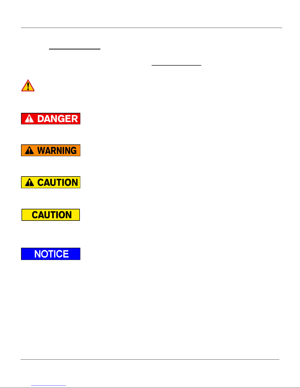
This manual follows the guidelines set forth in “ANSI Z535.4-2007” for alerting you to possible
hazards and their potential severity.
This is the safety alert symbol. It is used to alert you to potential personal injury hazards.
Obey all safety messages that follow this symbol to avoid possible injury or death.
! DANGER indicates an imminently hazardous situation which, if not avoided, will result in death or
serious injury.
! WARNING indicates potentially hazardous situation which, if not avoided, could result in death or
serious injury.
! CAUTION indicates a potentially hazardous situation which, if not avoided, may result minor or
moderate injury.
CAUTION without the safety alert symbol is used to address practices not related to personal
injury. (In this manual we use it to alert you to potentially hazardous situation which, if not avoided,
may result in property damage.)
NOTICE without the safety alert symbol is used to address practices not related to personal injury.
(In this manual we use it to alert you to special instructions, steps, or procedures.)
Rev 1.1 6
Page 7

ILF 33/44/55 Installation Manual
3 Important Information
Before Getting Started
“READ FIRST”
The ILF liftgate is a heavy duty industrial hydraulic lifting device. Performance and reliability
are closely related to proper installation, battery cable connections, and grounding. All
grounding surfaces MUST be cleaned, prepped, and sealed per this manual. “Cut to size”
cables MUST be properly crimped and sealed as factory supplied. All connections MUST be
dressed with dielectric grease or equivalent sealer.
Review lift gate invoice, packing slip, and installation drawing to assure delivery of correct gate
and complete delivery of accessories and optional equipment.
Read and understand the “Installation Manual” and “Owner’s Manual” in their entirety before
starting your Installation.
Refer to your truck manufacturer’s instructions before adding any auxiliary equipment. Installer is
responsible for compliance with this manual, OEM and FMVSS requirements.
All welding should be performed by qualified personnel per AWS standards.
Always Ground closest to your welding point to prevent arcing through moving parts or electrical
parts.
Contact PALFINGER Liftgates for Special Installations not covered in this Installation Manual.
Do not paint cylinder shafts or nylon bearings (Use non-chlorinated brake cleaner to remove over
spray)
Final Check-Off-Sheet at rear of this manual MUST be filled out and kept in your records for
future reference.
Refer to owner’s manual for Operation and Maintenance information.
Check the battery voltage before installation. Flooded lead acid batteries should measure 12.6V
and AGM batteries should measure 12.8V. If batteries are not at these voltages, fully charge
before installation
Rev 1.1 7
Page 8

ILF 33/44/55 Installation Manual
Improper operation of this liftgate may result in severe personal injury or death. DO NOT
operate unless you have been properly instructed, have read and are familiar with the
procedures in this manual. This manual has been designed to illustrate the steps needed for
the basic installation of the ILF liftgate. It also provides safety information and simple
preventive maintenance tips.
This manual is not intended for use as a repair or troubleshooting guide. Repairs should be
performed by a Palfinger Liftgates Authorized Service Center.
This manual has been designed for use in conjunction with the ILF series liftgates only which is
designed for different capacities. There are four options to determine the model and serial number of
the installed liftgate:
1) Refer to the serial number tag on the liftgate (Top of Mount Frame).
2) Ask your employer or lessor;
3) Call your PALFINGER Liftgates Authorized Service Center for assistance.
4) Call PALFINGER Liftgates for assistance in the USA at 888-774-5844. You can also contact
PALFINGER Liftgates by fax (562) 924-8318 or on the internet at www.palfinger.com
For technical support, contact PALFINGER Liftgates or an authorized PALFINGER service center.
www.palfinger.com
Rev 1.1 8
Page 9
ILF 33/44/55 Installation Manual
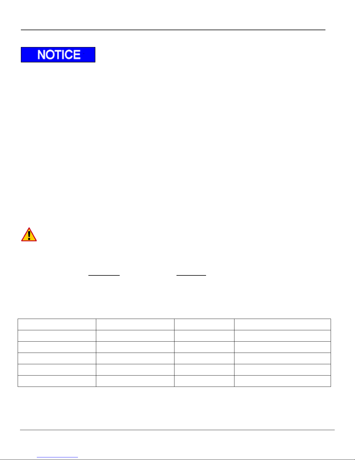
Metric Wrench Set
Basic Screwdrivers
Pliers
Wire Crimp Pliers
Digital Multimeter
Snap Ring Pliers
Hammer
Metric Allen Set 1.5mm-10mm
½” Impact & Sockets
Sm. Metric Socket Set
Assorted Drill Bits
Floor Jack or Equiv.
Sm. To Med. Bottle Jack
Forklift or O/H Crane
Hand Held Grinder
Paint Gun
Cutting Torch or Equiv.
3/8 Drill Motor
Pry Bar
Heat Gun or Equiv.
Min. 250 Amp Welder
Important Dimensions 3.1
Minimum Bed Height dimensions are ALWAYS MAXIMUM LOADED TRUCK.
Maximum Bed Height dimensions are ALWAYS DRY UNLOADED TRUCK.
Installing a gate at or close to minimum bed height normally results in a gate that will NOT open
and close from stored position if the minimum floor height is exceeded when truck is loaded.
Ensure trailer body does not interfere with installation or operation of the ILF liftgate series.
It is not recommended to cut, torch, or remove support materials from trailer. Removing gussets,
stiffeners, light rings, or other such support structures may VOID your trailer warranty.
Call technical support before starting the installation if any questions or concerns arise on
mounting dimensions or procedures.
Mounting Notes:
Read and clearly understand manual BEFORE beginning ANY work.
The basic rule of PALFINGER Liftgates‟s ILF installation is to lift mount frame
to achieve MAXIMUM ground clearance WITHOUT exceeding Min “F” dimension.
Recommended Tools 3.2
Rev 1.1 9
Page 10
ILF 33-44-55 Installation Manual
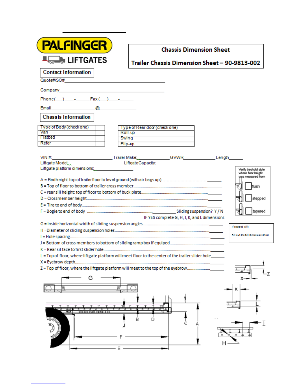
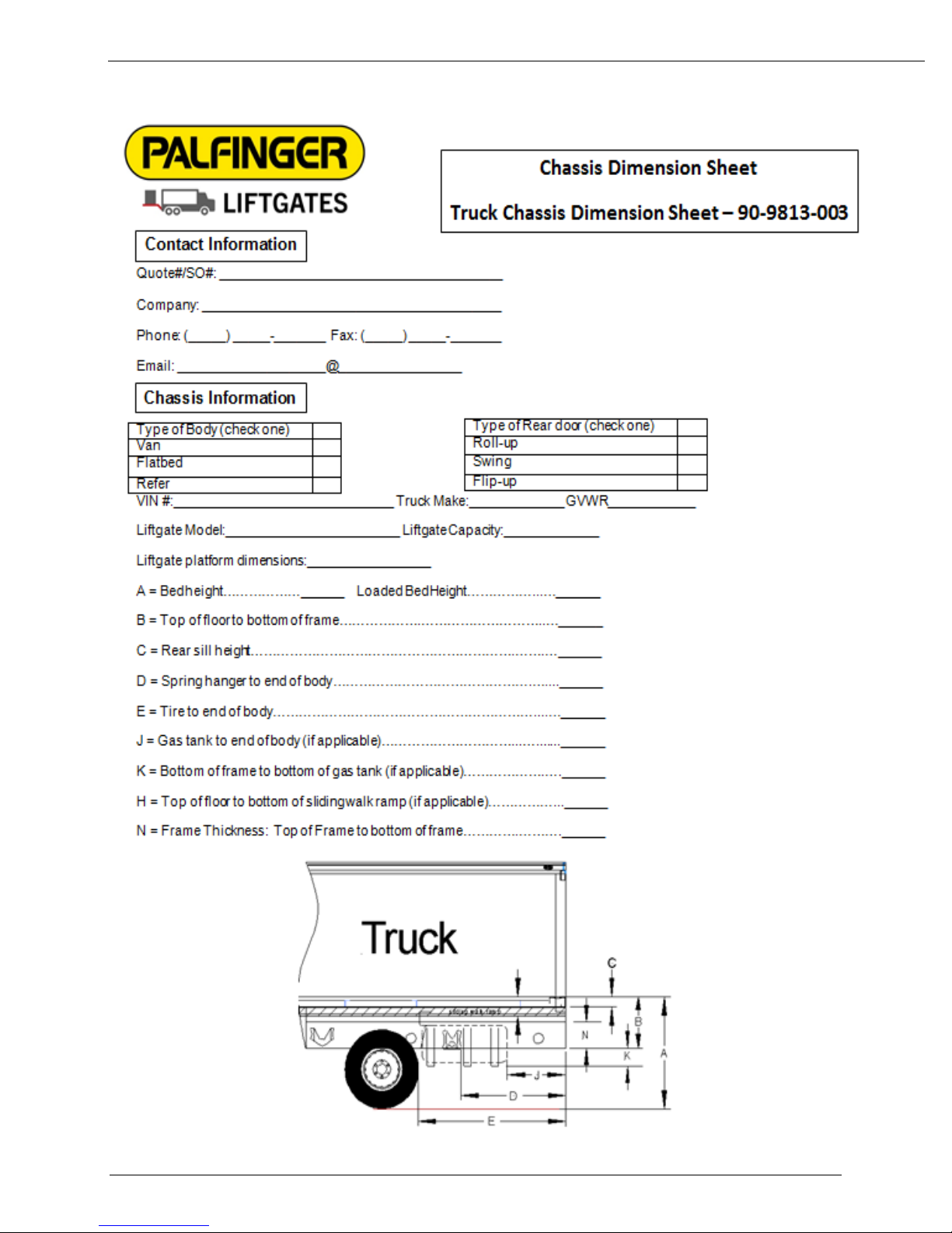
4 Dimension Sheet
Rev 1.1 10
Page 11
ILF 33-44-55 Installation Manual
Rev 1.1 11
Page 12
ILF 33/44/55 Installation Manual
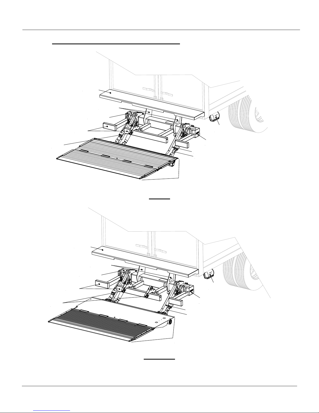
Bumper
Bed
Extension
Mount Frame
Tilt Arm
Lift Arm
Control
Box
Hydraulic
Power Unit
Aluminum
Platform
Mount Plates
Parting
Wheel
Bumper
Bed
Extension
Mount Frame
Tilt Arm
Lift Arm
Control
Box
Hydraulic
Power Unit
Steel/Aluminum
Platform
Mount Plates
Parting
Wheels
5 General Overview of ILF Liftgate
ILF 33
ILF 44/55
Rev 1.1 12
Page 13
ILF 33/44/55 Installation Manual
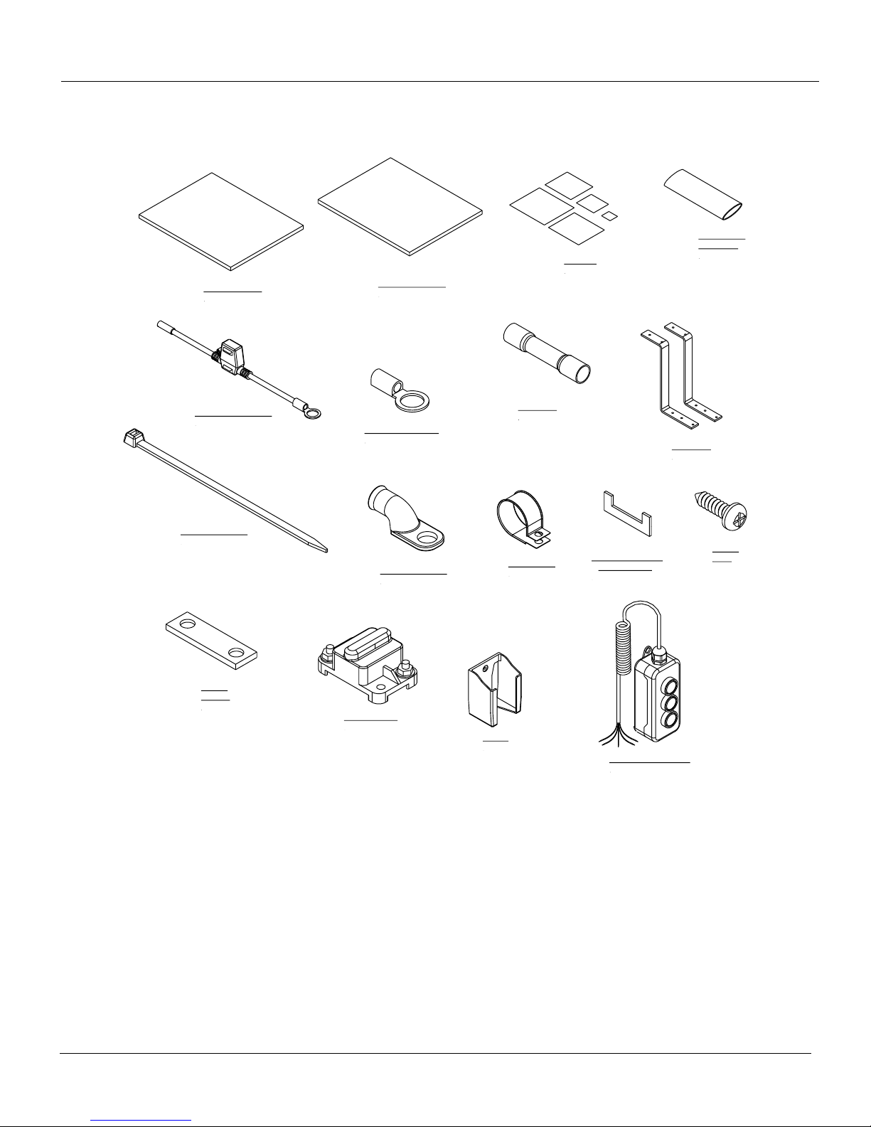
In-Line Fuse, 20 Amp
1 pcs
Heat Shrink,
ø1/2" x 3"L
1 pc
Copper
Bus Bar
1 pc
Circuit Breaker
1 pc
Owner's Manual
1 pc
Installation Manual
1 pc
Battery Lug, 5/16"
1 pc
Decal Kit
15 pcs
8" Nylon Cable Tie
12 pcs
Ring Connector, 3/8"
1 pc
Butt Splice
1 pcs
Holster
1 pc
3-Button Hand Control
1 pc
Cable Clamp
5 pcs
Screws
2 pcs
Mount Plate Gusset
Only for ILF 55
2 pcs
Z-Brackets
2 pcs
Boxed Items Included with Liftgate for Installation
Rev 1.1 13
Page 14
ILF 33/44/55 Installation Manual
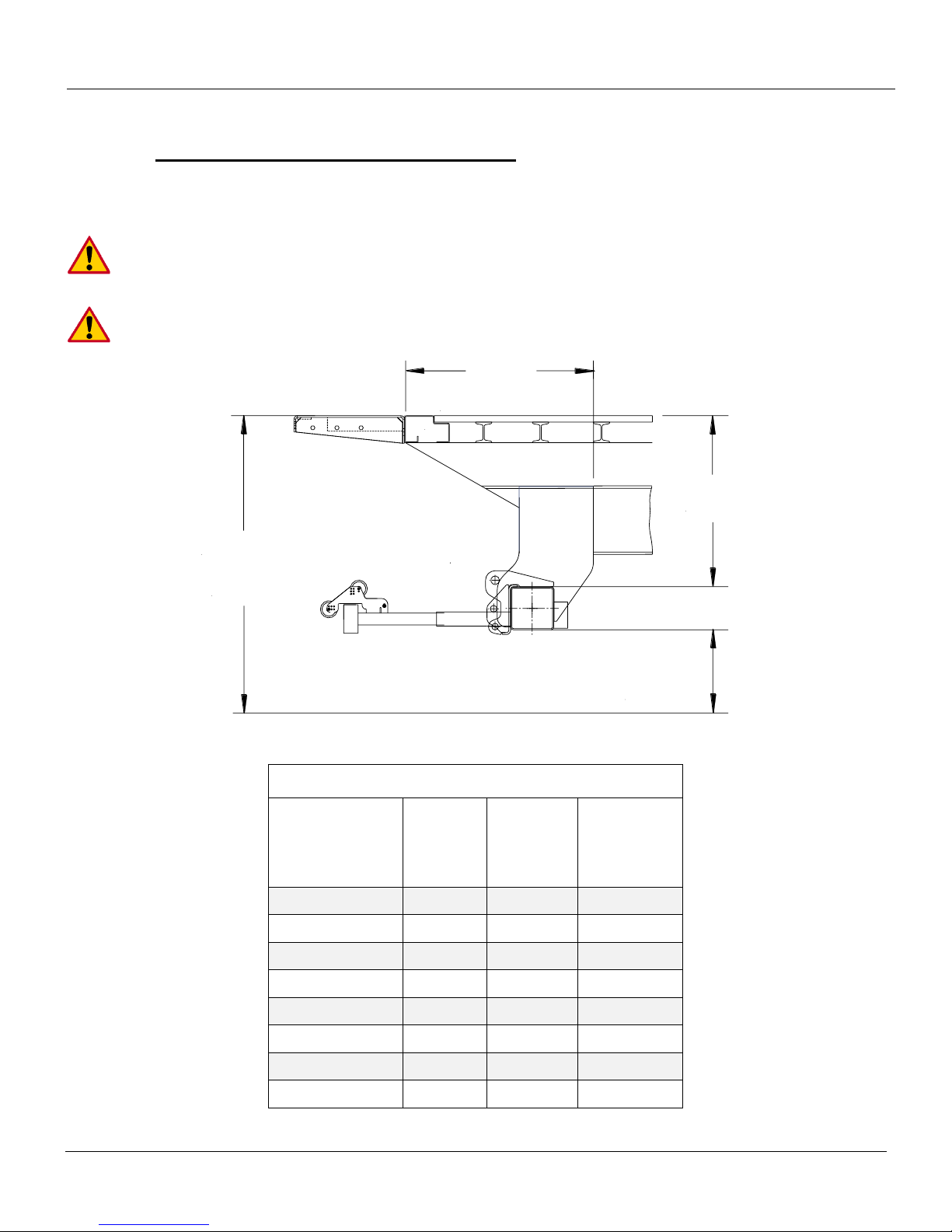
"K"
Mount Clearance
(Reference)
"F" Dim.
Bed Height
Max. 62"
Min. 46"
"G"
Ground
Clearance
Sill
ILF 33 Mounting Dimension Table
Bed Height
(Loaded)
F
Dim.
G
Dim.
K
Dim.
(Ref.)
62“
33“
20“
29“
58“
32“
19“
30“
56“
31“
18“
31“
54“
30“
17“
31.5“
52“
29“
16“
32.5“
50“
28“
15“
33“
48“
27“
14“
34“
46“
26“
13“
35“
6 Chassis and Body Preparation
Installation Dimensions 6.1
IMPORTANT:
Always use the smallest F-dim possible for best ground clearance
(Don‟t exceed max. ground clearance)
Minimum bed height is when truck/trailer is loaded to MAX GVW
Rev 1.1 14
Page 15

ILF 33/44/55 Installation Manual
22"
12"
18"
13"
21"
12"
17"
13"
Assuming 26" F-Dimension
Assuming 27" F-Dimension
Assuming 28" F-Dimension
Cut
Assuming 29" F-Dimension
Assuming 30" F-Dimension
Assuming 31" F-Dimension
Assuming 32" F-Dimension
Assuming 33" F-Dimension
Cut
Cut
Cut
Spacer
Bed Extension
Sill
(Over 4"
in Height)
Chassis
Cut
Fig. 1
Fig. 2
Chassis Cut Out ILF 33 6.2
These dimensions are starting points due to variation of installations. The final dimensions
may vary depending on actual installation F-Dim.
1. Determine the correct frame cut out according to your specific bed height. With long overhangs it is
even more important to maintain min F = Max ground clearance, Fig. 1.
2. If the vehicles sill measures more than 4” in height, add a spacer to the rear of the vehicle, Fig. 2.
The spacer will shift the bed extension back allowing the platform to clear the bottom of the sill when
it is in stored position. Reference cutout dimensions from Step 1 to determine the chassis cutout.
Rev 1.1 15
Page 16
ILF 33/44/55 Installation Manual
"K"
Mount Clearance
(Reference)
"F" Dim.
Bed Height
Max. 55"
Min. 50"
"G"
Ground
Clearance
Sill
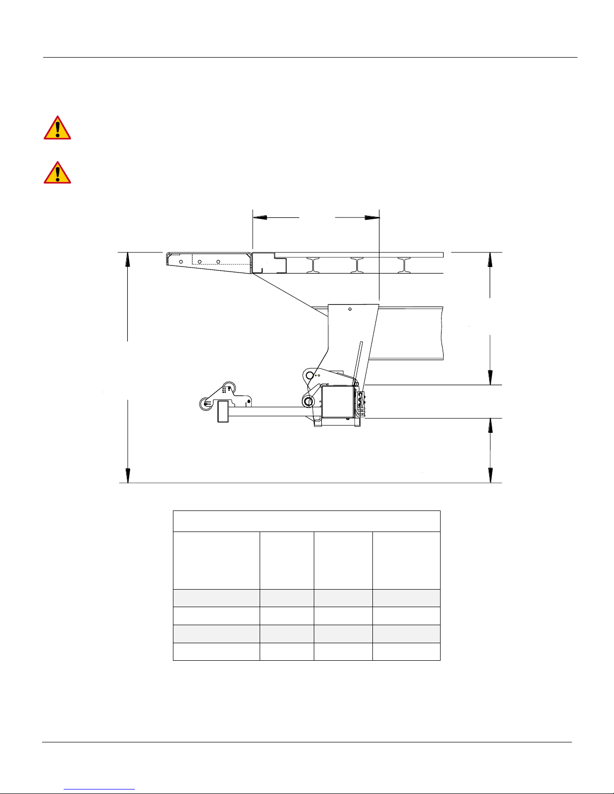
ILF 44/55 Mounting Dimension Table
Bed Height
(Loaded)
F
Dim.
G
Dim.
K
Dim.
(Ref.)
55“
28“
19.5“
26“
54“-53“
27“
19“
27“
52“-51“
26“
18“
28“
50“
25“
17“
29“
6.2.1 Installation Dimensions ILF 44 and ILF 55
IMPORTANT:
Always use the smallest F-dim possible for best ground clearance
(Don‟t exceed max. ground clearance)
Minimum bed height is when truck/trailer is loaded to MAX GVW
Rev 1.1 16
Page 17

ILF 33/44/55 Installation Manual
22"
12"
18"
13"
21"
12"
17"
13"
Assuming 26" F-Dimension
Assuming 27" F-Dimension
Assuming 28" F-Dimension
Cut
Assuming 29" F-Dimension
Assuming 30" F-Dimension
Assuming 31" F-Dimension
Assuming 32" F-Dimension
Assuming 33" F-Dimension
Cut
Cut
Cut
Spacer
Bed Extension
Sill
(Over 4"
in Height)
Chassis
Cut
Fig. 3
Fig. 4
Chassis Cut Out ILF 44/55 6.3
These dimensions are starting points due to variation in installations. The final dimensions
may vary depending on actual installation F-Dim.
3. Determine the correct frame cut out according to your specific bed height. With long overhangs it is
even more important to maintain min F = Max ground clearance, Fig. 3.
4. If the vehicles sill measures more than 4” in height, add a spacer to the rear of the vehicle, Fig. 4.
The spacer will shift the bed extension back allowing the platform to clear the bottom of the sill when
it is in stored position. Reference cutout dimensions from Step 1 to determine the chassis cutout.
Rev 1.1 17
Page 18
ILF 33/44/55 Installation Manual
Chassis
Wooden Spacer
1/4" Thk
Flat Bar
2"x3"x3/16"
Angle
Chassis
Wooden Spacer
1/4" Thk
Flat Bar
2"x3"x3/16"
Angle
Sill
Vehicle Frame Cutout
Rear of Vehicle
Body Long Rail
Frame Cap
Fig. 5
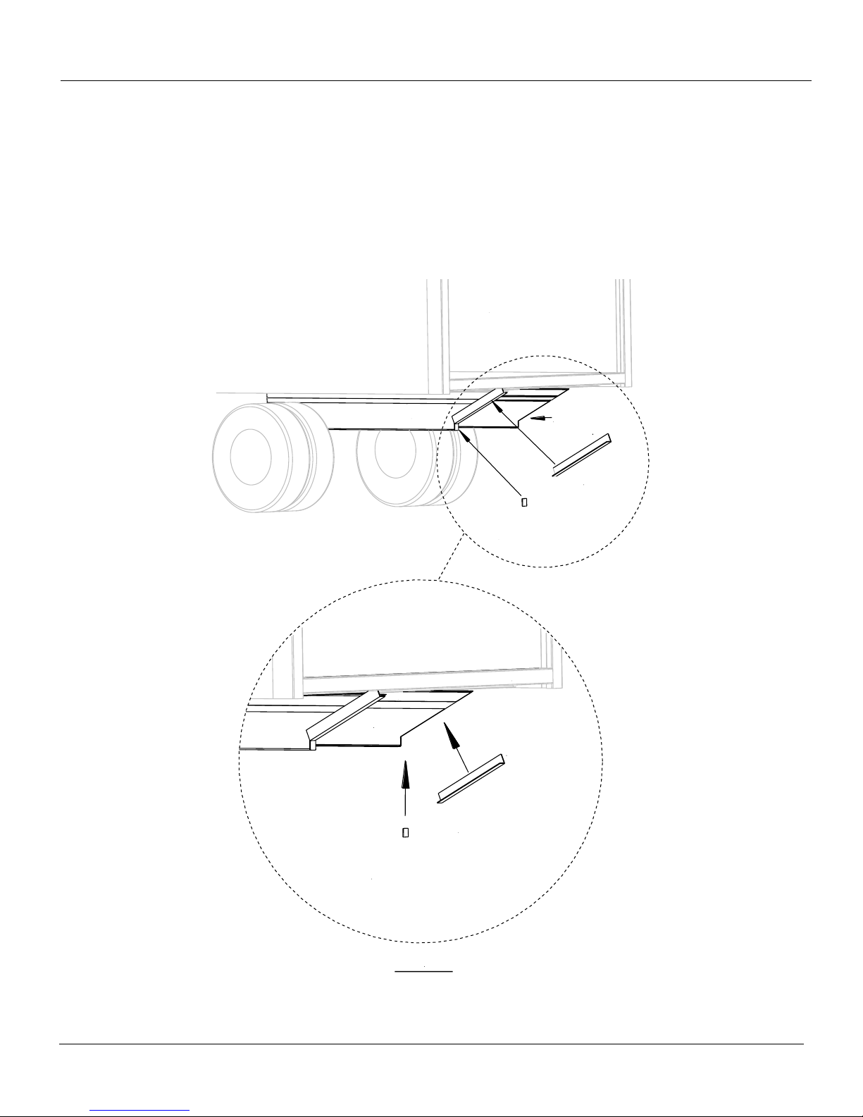
Frame Cap 6.4
Capping the frame cut outs is recommended to help protect the liftgates platform from being damaged,
Fig. 5.
NOTE: Palfinger Liftgates does not supply cap materials. All material must be supplied by end user.
1. Suggested components: 2”x3”x3/16” angle, and ¼” flat bar stock. Cut material to size.
Rev 1.1 18
Page 19

ILF 33/44/55 Installation Manual
NOTES
Rev 1.1 19
Page 20
ILF 33/44/55 Installation Manual
Bed Extension
Sill
Weight
300-500 lbs Min.
Weight
300-500 lbs Min.
48" Channel
C-Clamp
102"
16"
1" Channel Offset
96"
Trim
Trim
C-Clamp
C
L
Floor
Vehicles
Rear
Corner
Posts
C
L
Fig. 6
Fig. 7
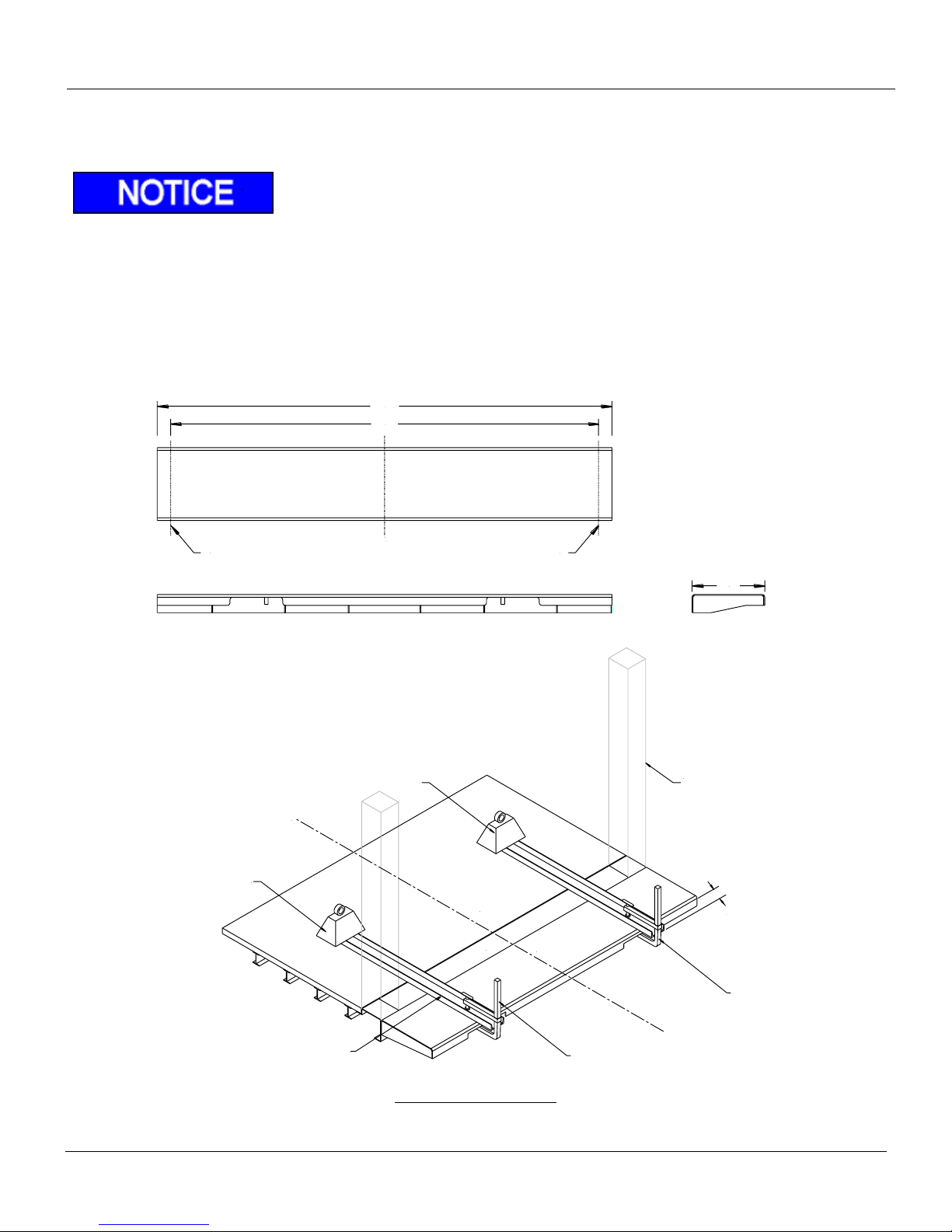
Bed Extension Installation 6.5
NOTE: Standard bed extension measures 102” wide, for 96” vehicles, trim each end, Fig. 6.
1. Center bed extension to vehicle body. Lay channels flush with the bed extension, sill, and floor. If tack
welding the channels, tack weld channels or angles to bed extension and sill. If not tack welding the
channels, use proper weights and clamps to maintain channels in a flush position. Keep the channels
in place as they will serve to level the platform during installation, Fig. 7.
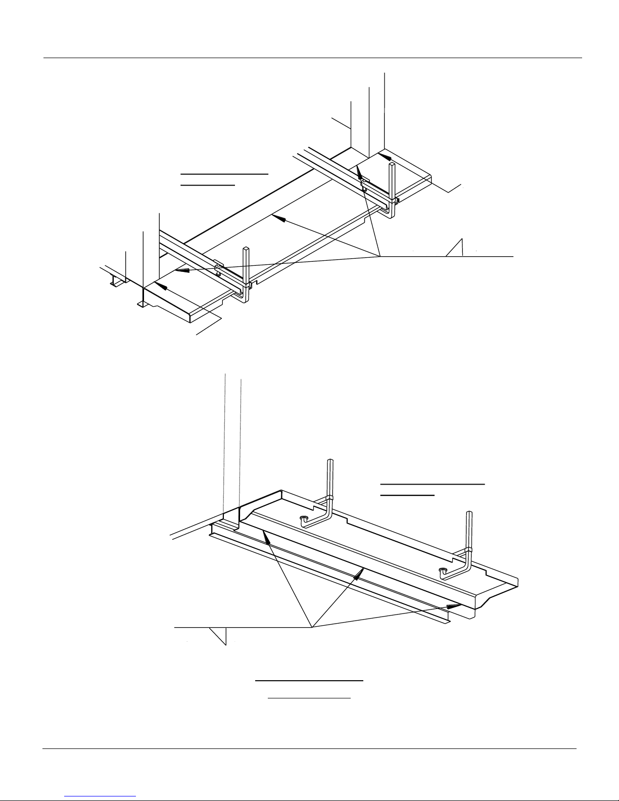
2. Verify bed extension is centered on body and flush with channel.
3. Weld 3/16” x 4” welds on approximately 10” centers and alternate welds on top and bottom of bed
extension. Do not weld across the corner posts, Fig. 8.
Rev 1.1 20
Bed Extension Installation
Page 21
ILF 33/44/55 Installation Manual
Do Not
Weld Area
3/16"
Bottom of Bed Extension
Welding Area
Do Not
Weld Area
4-10
3/16"
4-10
Top of Bed Extension
Welding Area
Fig. 8
Rev 1.1 21
Weld-On Bed Extension
Welding Locations
Page 22
ILF 33/44/55 Installation Manual
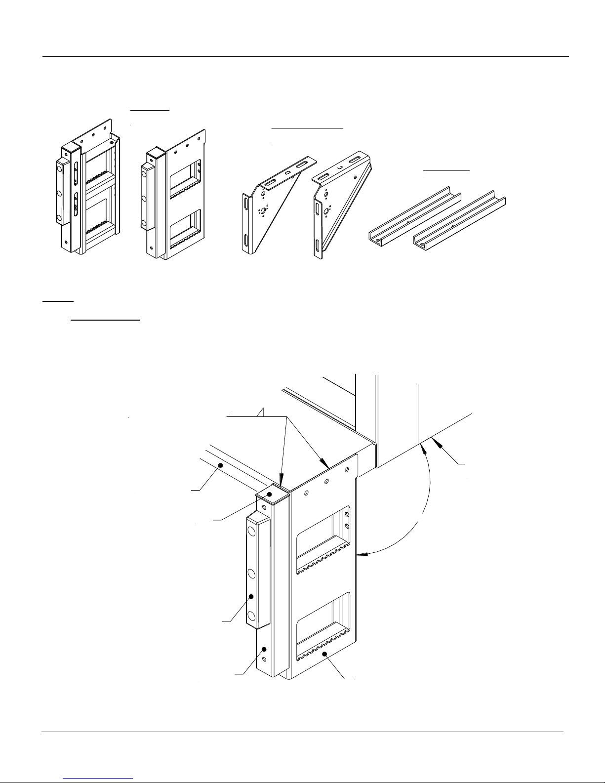
Dock Bumper
1pc Curb Side
1pc Street Side
Dock Bumper Strut Brace
1pc Curb Side
1pc Street Side
Support Channel
2 pcs
Bed Extension
Vehicle
Body
3/16"
90°
Dock Bumper
Rubber
Bumper
Extension
Channel
Plastic
Cap
Fig. 9
Dock Bumper Installation – Weld On (Optional) 6.6
Steps:
1. Dock Bumper:
Position the dock bumper against the bed extension; make sure everything is squared vertically and
horizontally. Clamp dock bumpers onto the bed extension. Remove the plastic cap from the top of the
extension channel prior to welding. Tack weld the bumper to the bed extension, Fig. 9.
Rev 1.1 22
Page 23
ILF 33/44/55 Installation Manual
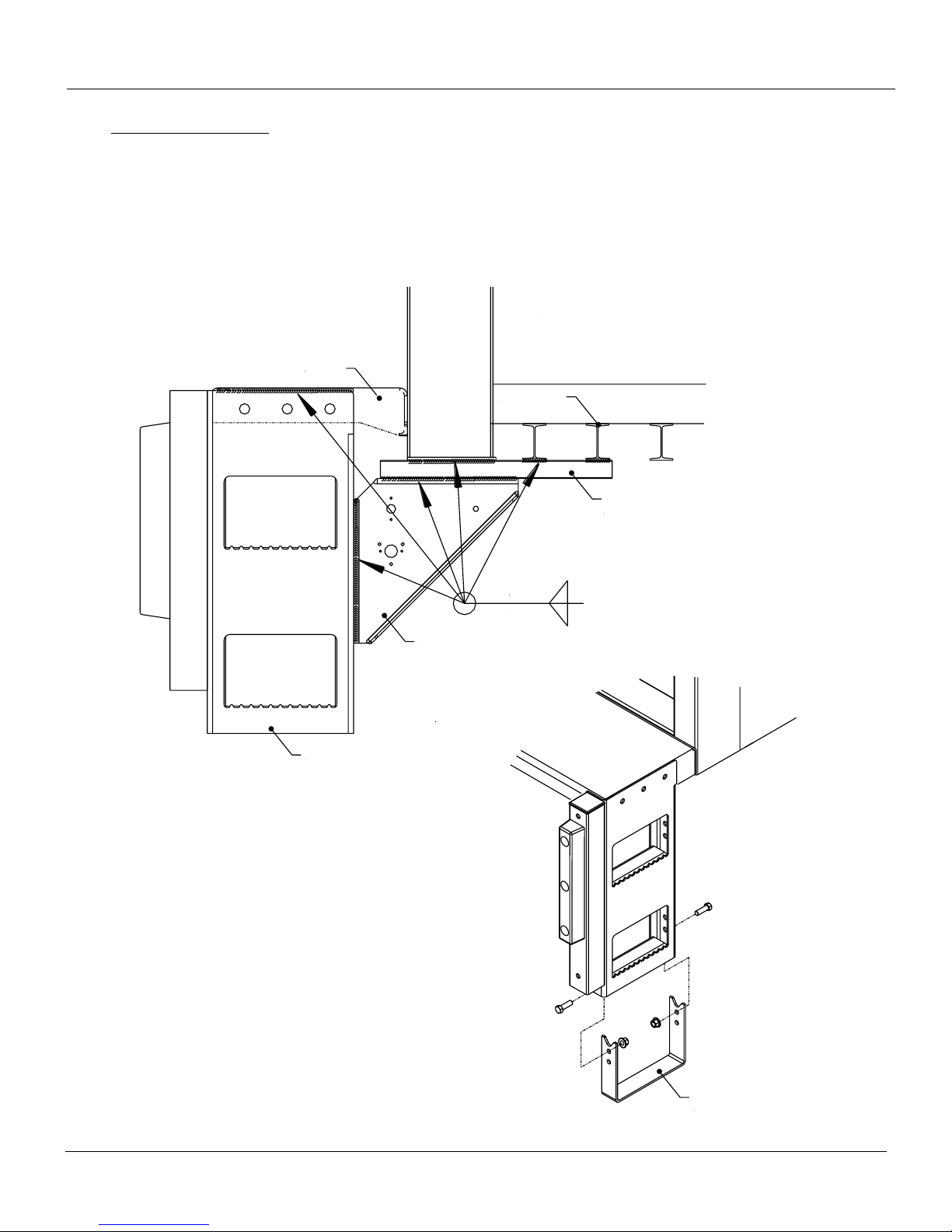
Dock Bumper Extension Step
(Optional Accessory)
3/16"
3/16"
Dock Bumper
Strut
Support
Channel
Bed
Extension
Vehicle Body
Cross Members
Fig. 10
2. Dock Bumper Struts:
Before welding the struts and support channels, make sure the channels are properly adjusted for
optimum installation. Position the support channels perpendicular to a minimum of three of the vehicles
cross members, move the channel horizontally for adjust if necessary, Fig. 10. Use clamps or similar
devices to hold the support channels in place. Next position the strut against the dock bumper and
support channel, clamp in place. Finally, weld all components 100% as shown.
Rev 1.1 23
Page 24

ILF 33/44/55 Installation Manual
Secure
Fig. 11
7 Liftgate Installation (Truck)
Warning: Never work or place yourself under unsupported platform
High heat and spatter from welding can damage components. Make sure
components such as hoses, lines, and wires are clear of or protected from heat and spatter caused
by welding.
Prior to beginning installation, assure the vehicle is on a leveled surface.
NOTE: The installation process for an ILF 33, ILF 44, and ILF 55 is the same for all gates. For
illustration purposes, an ILF 44 is shown.
Protect all wires and cable from dropping slag or splatter when welding mount plates.
Make sure to have power pack pulled out when welding the tube and hoses and cables
are away from walls..
Do no apply a load to the platform at anytime during installation.
Installation 7.1
1. Hoist Platform: Unfold platform manually and clamp forklift forks, overhead crane or equivalent to
platform. Make sure the platform is secured. Always maintain the mount tube centered to the
vehicles body, Fig. 11.
Rev 1.1 24
Page 25
ILF 33/44/55 Installation Manual
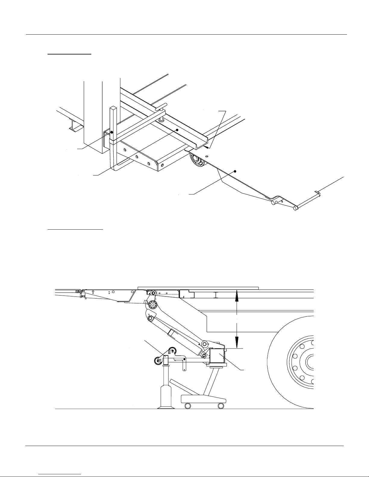
3" Channel
Platform
Clamp
Channel flush
with platform
"F" DIM.
Secondary
Jack
Primary
Jack
Under
Ride
Guard
Mount
Frame
Tube
Fig. 12
Fig. 13
2. Raise Platform: Clamp 3” channels over the bed extension and align the front edge of the platform,
to the back edge of the bed extension, Fig. 12. Maintain the top of the platform flush to the bed
extension (channel).
3. Set “F” Dimension: “F” Dimension should be determined from Section 6 of this manual. Use floor
jack or equivalent to position the frame assembly up to the required “F” dimension, Fig. 13. Use a
second jack to level out the under ride guard, if necessary. Check for squareness vertically and
horizontally. 12V power supply may be required to release pressure on lift cylinder valves, if power is
required continue to the Electrical Installation in Section 9.
Rev 1.1 25
Page 26
ILF 33/44/55 Installation Manual
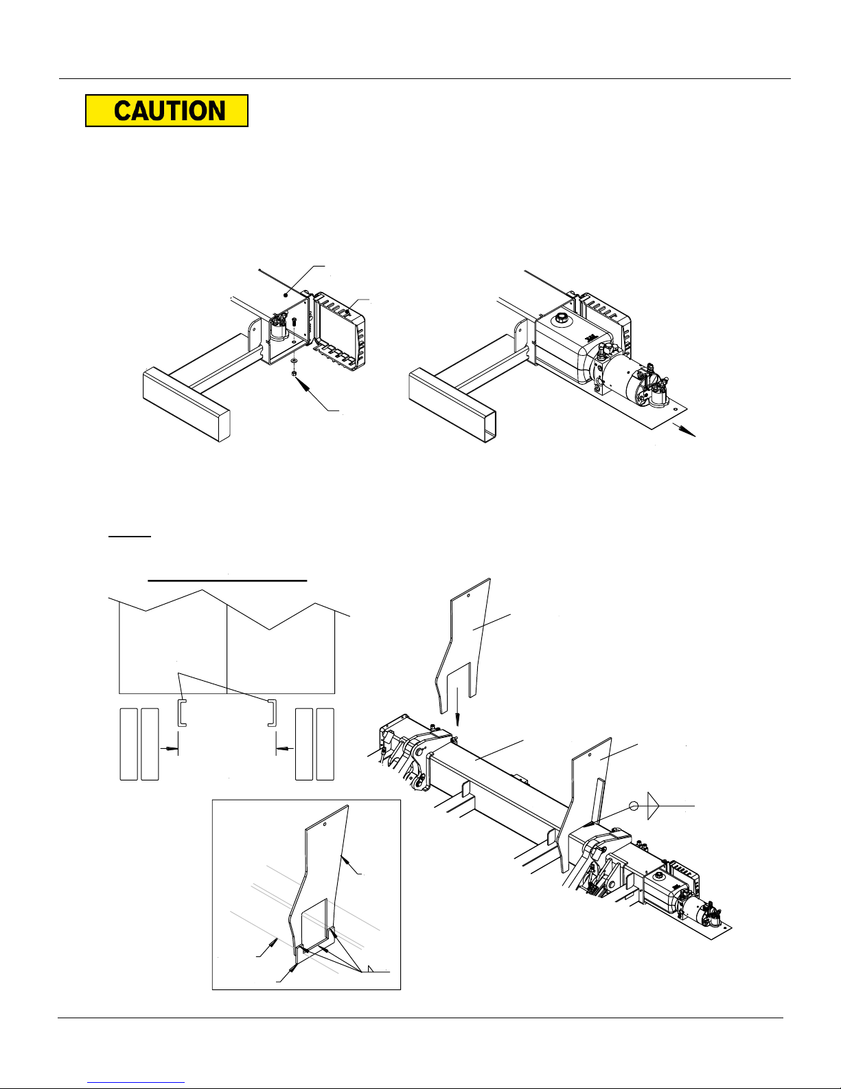
Cover
Mount
Tube
Hardware
Pull Out
3/16"
Mount Tube
Mount Plate
Mount Plate
Dimension determines
the distance of the
mount plates.
Truck
Frame
3/16"
Rear View of Truck Frame
Mount Plate
Mount Tube
Gusset
3/16"
Fig. 15
Fig. 14
Fig. 16
Pull out power tray before welding. Power Tray is located inside the
mount tube and can be accessed through the curb side of the mount tube.
4. Pull out the power pack tray approximately 20” out of the mount tube by removing the bolt on the
curbside and detach the ground strap and control power connector from the tray, Fig. 14.
Disconnect hoses, if necessary, to pull out tray far out. Verify hoses and cables are not in contact
with the inside walls of the tube prior to welding.
5. Weld the mount plates to the liftgates mount tube. Remember to keep the mount tube centered to
the truck. Determine the overall width of the frame and position the mount plates at the same
distance. Weld all around the mount plates and tube on both sides of the mount plates, Fig. 15.
NOTE: ILF 55 will have an additional brace that’s required at the bottom of the plate, Fig. 16.
Rev 1.1 26
Page 27
ILF 33/44/55 Installation Manual
90°
Support
Jacks
Wooden Spacer
Chassis Frame
Body Stringer
Wooden Spacer
Chassis Frame
Body Stringer
8.00" Overlap
Support Plate
(if necessary)
Mount Plate
3/16"
3" channels
Fig. 17
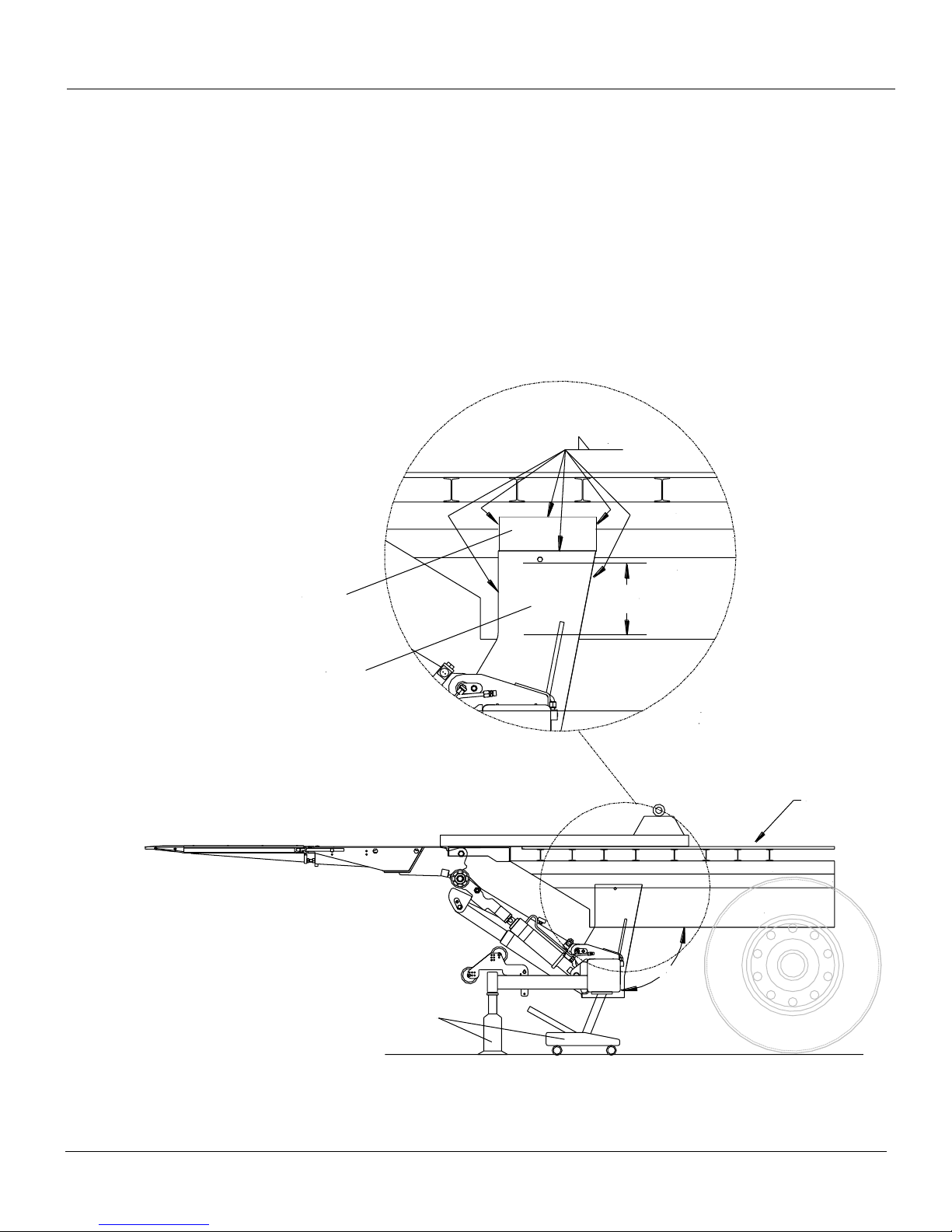
6. Place the mount tube in the predetermined position, keeping the given maximums and minimums
dimensions in mind. Support the mount tube using a rolling floor jack or a similar device to position
the mount tube and clamp plates. Make sure the mount tube is squared 90-degreed, vertically and
horizontally, to the truck frame. Use a minimum of 8” overlap between the mount plates and truck
frame. Clamp mount plates to the chassis frame to prevent any misalignment before welding. Tack
weld mount plates to vehicle frame.
Recommendation: Add a support plate to the top of the mount plates, if needed, to tie liftgate mount
plates to the body stringer, Fig. 17.
NOTE: When the mount plate is welded on the chassis frame, the ground (electrical) from the
chassis is transferred to the liftgate through the weld.
Rev 1.1 27
Page 28
ILF 33/44/55 Installation Manual
B15 PLATFORM
3" channels
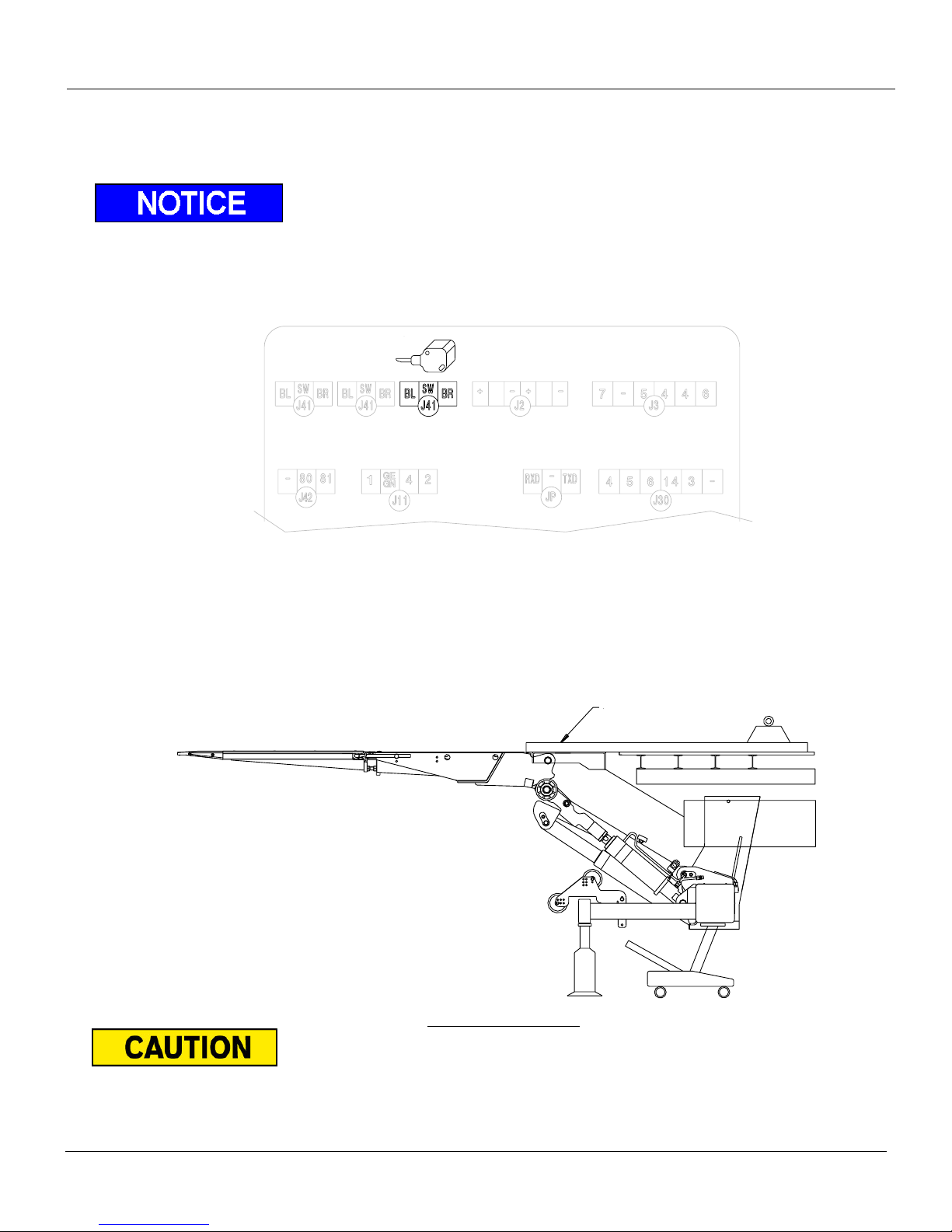
7. Proceed to the electrical installation, Section 9.
To adjust the tilt cylinder during installation, disconnect the B-15 sensor at J41 on the control board.
Remember to reconnect the B-15 sensor back into J41 on the control board after any
adjustments are done, Fig.
.
8. After completion of the electrical installation, Raise platform to be flush with the 3” channels. If the
platform is not flush, the mount tube will need to be adjusted, remove tack welds and make
adjustments to get the platform to be flush. If the platform is leveled with the 3” channels, proceed
with completing the installation.
Be extremely cautious when testing. Remember that the Liftgate is only tack welded in place,
DO NOT APPLY A LOAD. Do not power up against the bed extension.
Rev 1.1 28
.
Supported Mount Frame
Page 29
ILF 33/44/55 Installation Manual
9. After verification of everything being aligned, proceed to welding the unit completely. Weld 100%
with ¼” welds against the frame and both sides of the plates against the mount frame.
Before running the unit through its cycle, make sure that the In-Cab Switch is in the “ON”
position (Lights are on).
Before running the unit through its cycle, make sure that the solenoids on the lift cylinders are
not hitting the mount plates.
Rev 1.1 29
Page 30
ILF 33/44/55 Installation Manual
Trailer Frame
w/Sub-Frame
Channels
Dimension determines
the distance of the
mount plates.
Crossmembers
Crossmember
Subframe
Channel
Trailer
Sliding
Rail
3/16"
3/16"
Weld to
Multiple
Cross
Members
Fig. 18
8 Liftgate Installation (Trailer)
Warning: Never work or place yourself under unsupported platform
High heat and spatter from welding can damage components. Make sure components such as
hoses, lines, and wires are clear of or protected from heat and spatter caused by welding.
Prior to beginning installation, assure the vehicle is on a leveled surface.
Installation 8.1
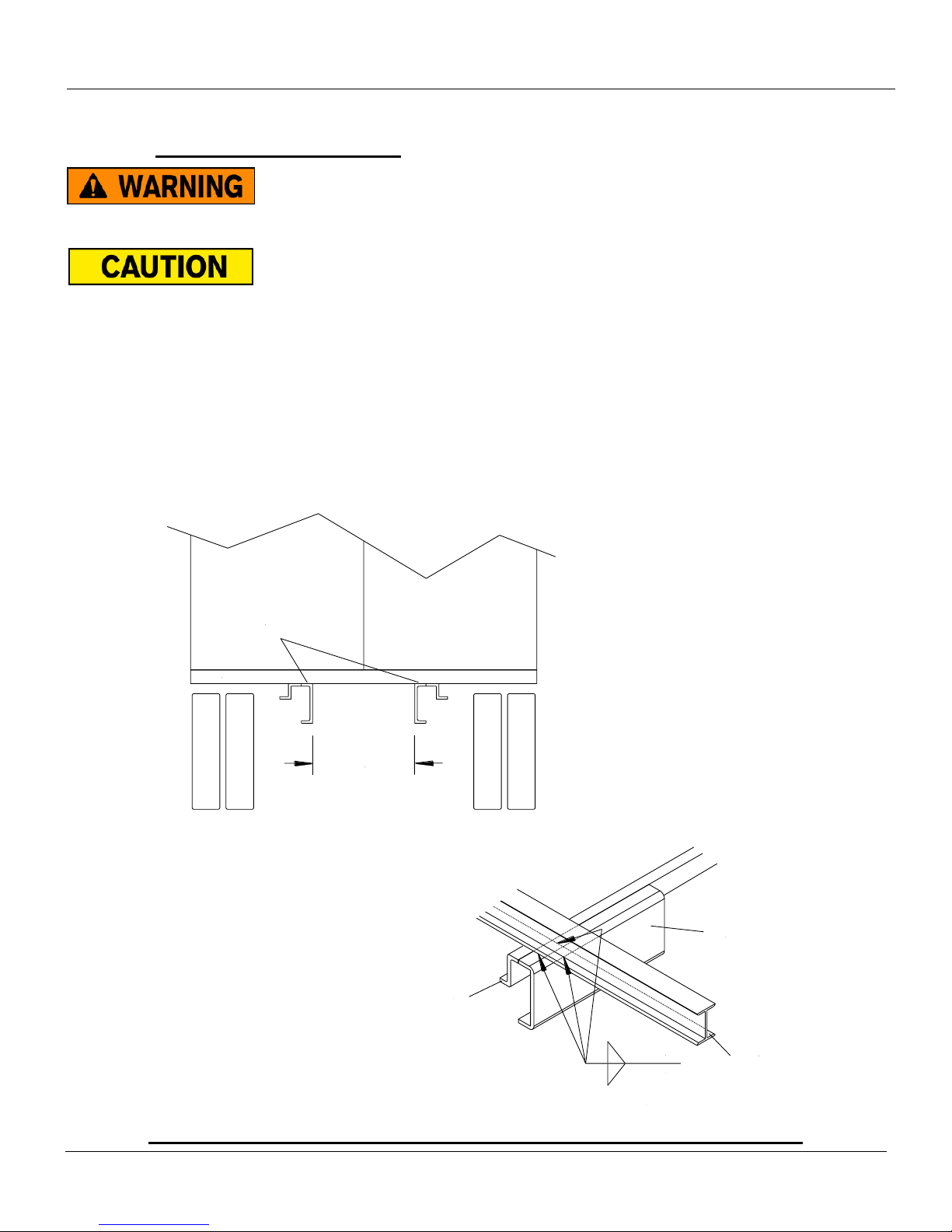
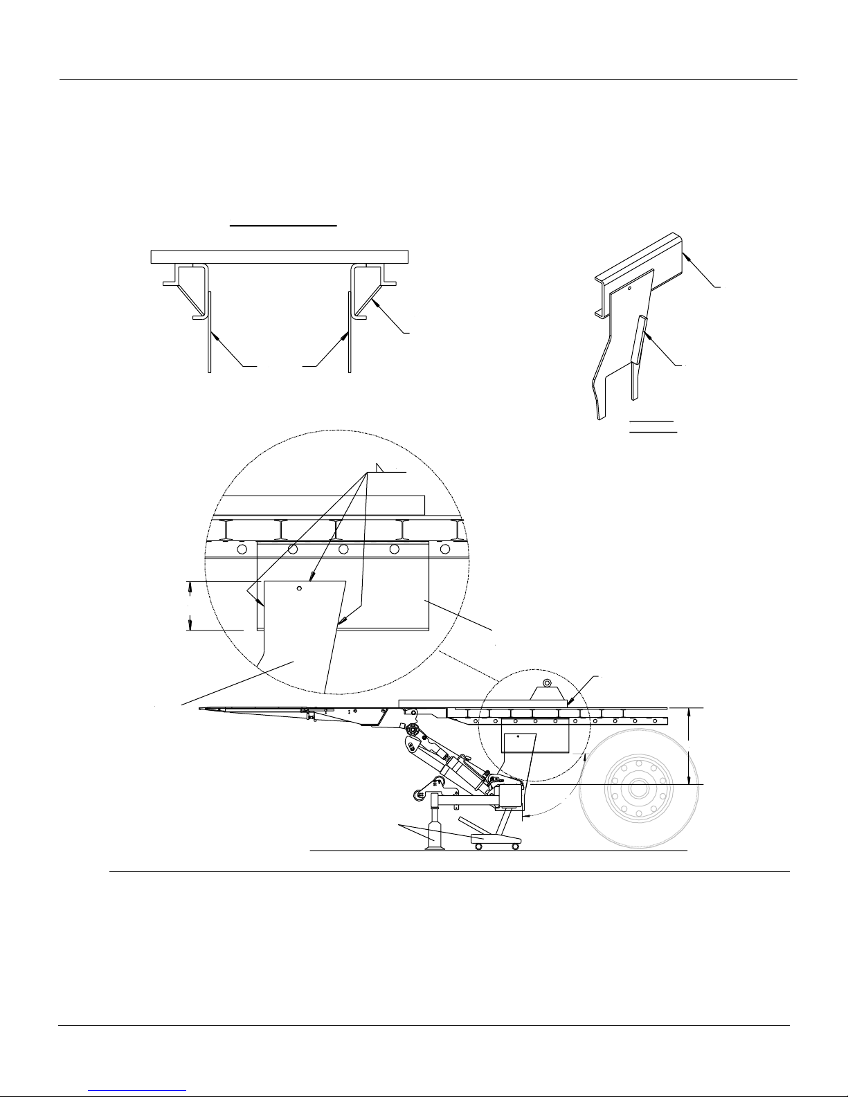
1. Install the sub-frame channels onto the trailer chassis. Weld the sub-frame channels onto as many
cross members as possible, Fig. 18. The inside distance of the channels will determine what
distance the mount plates will be installed.
Rev 1.1 30
Page 31
ILF 33/44/55 Installation Manual
90°
F-Dimension
Support
Jacks
3" channels
Sub Frame
Channel
Sub Frame
Channel
Rear View of Trailer
Recommended Support
Plates along sub-frame
channel for strength
(Not supplied by Palfinger)
Mount Plate
Sub-Frame
Channel
Street Side
Mount Plate
8.00"
Overlap
Mount Plate
3/16"
Mount
Plates
2. Place the mount tube in the predetermined position, keeping the given maximums and minimums
dimensions in mind. Support the mount tube with a rolling floor jack or a similar device to position
the mount tube. Make sure the mount tube is squared 90-degreed, vertically and horizontally, to the
trailer. Use a minimum of 8” overlap between the mount plates and sub-frame channel. Clamp
mount plates to sub-frame to prevent any misalignment before welding.
3. Proceed to the electrical installation, Section 9.
Rev 1.1 31
Page 32
ILF 33/44/55 Installation Manual
B15 PLATFORM
3" channels
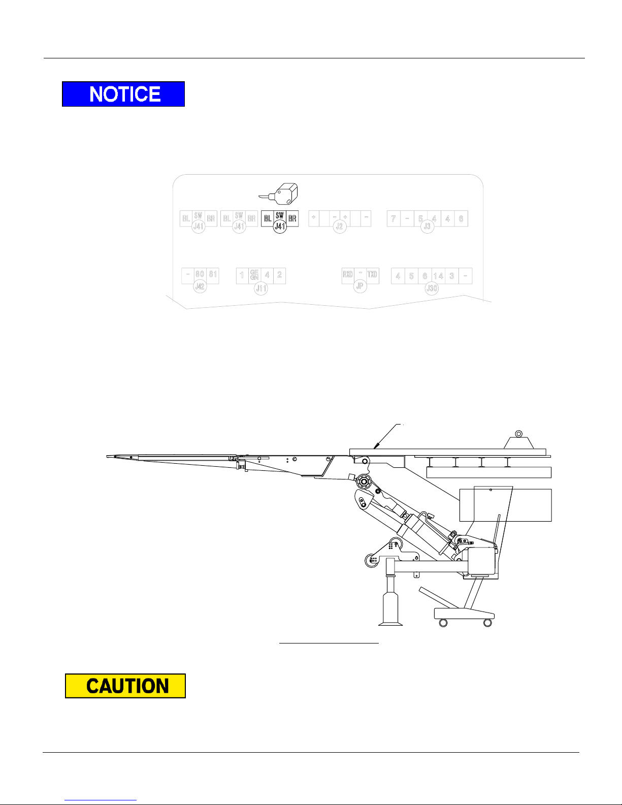
To adjust the tilt cylinder during installation, disconnect the B-15 sensor at J41 on the control board.
Remember to reconnect the B-15 sensor back into J41 on the control board after any
adjustments are done
.
4. After completion of the electrical installation, Raise platform to be flush with the 3” channels. If the
platform is not flush, the mount tube will need to be adjusted, remove tack welds and make
adjustments to get the platform to be flush. If the platform is leveled with the 3” channels, proceed
with completing the installation.
Be extremely cautious when testing. Remember that the Liftgate is only tack welded in place,
DO NOT APPLY A LOAD. Do not power up against the bed extension.
Rev 1.1 32
Supported Mount Frame
Page 33
ILF 33/44/55 Installation Manual
5. After verification of everything being aligned, proceed to welding the unit completely. Weld 100%
with ¼” welds against the frame and both sides of the plates against the mount frame.
Before running the unit through its cycle, make sure that the In-Cab Switch is in the “ON”
position (Lights are on).
Before running the unit through its cycle, make sure that the solenoids on the lift cylinders are
not hitting the mount plates.
Rev 1.1 33
Page 34
ILF 33/44/55 Installation Manual
T I R E
Cable Cover/Clamp
B-15 Sensor
Liftarm
Platform Profile
Warning Light/Foot Control
(option) Harness
Warning Light/Foot Control (option)
MUST have all connectors inserted into
.
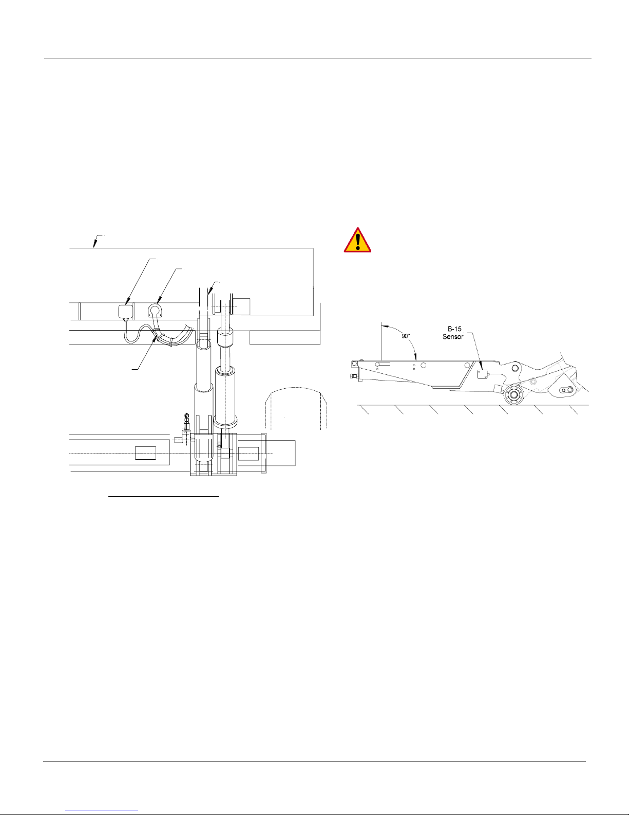
Fig. 19
Operation of B-15 Sensor 8.2
The B-15 Sensor allows the platform to tilt, up or down, once it has reached a minimum height off the
ground, Fig. 19. The sensor will not allow the platform to tilt after a certain height off the ground for safety
purposes. The titling function allows the platform to tilt down as close as possible to the ground for easy
loading and unloading of cargo.
To adjust the B-15 sensor, if necessary:
1. Loosen (2) 5mmx50mm Allen Head sensor mount screws and rotate slightly for re-adjustment.
Fasten screws after adjustment is complete.
platform profile after connections are made
Bottom View of Platform
Rev 1.1 34
Page 35
ILF 33/44/55 Installation Manual
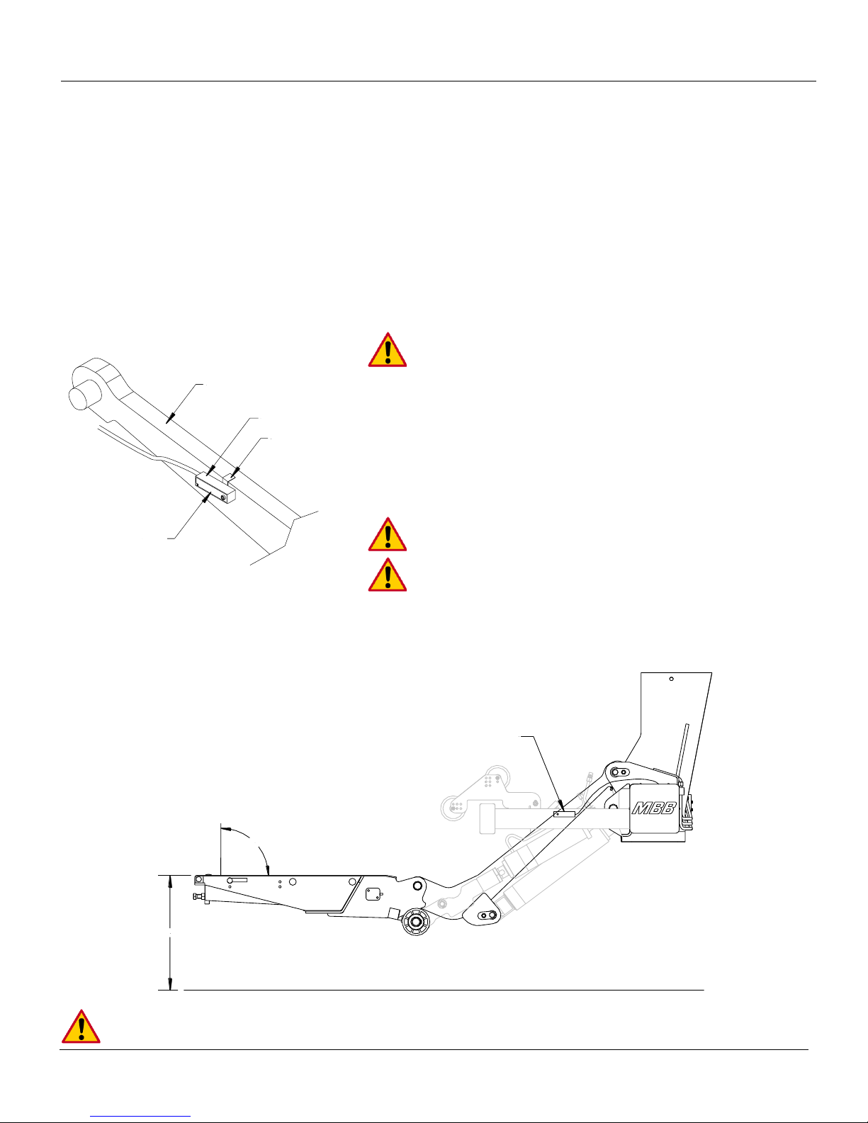
Lift Arm (Curb Side)
B-13 Sensor
Lock Tab
Resin
B-13 Sensor
12"-15"
90°
Fig. 20
Operation of B-13 Sensor 8.3
The B-13 Sensor allows the lift arm to, Fig. 20:
1. Raise platform approximately 12-15” off ground and verify platform is level (tilt if necessary).
2. Loosen lock bolt and set sensor level with platform/ground (verify colored side of sensor is out).
3. Lower platform to ground. When properly set, platform should remain leveled for approximately two
to five seconds then tilt the platform tip to ground.
4. Cycle Platform from bed height to ground several times to verify proper operation. Tilt sensor slightly
forward or back to achieve proper Auto-Tilt action.
At NO time should the platform tilt tip towards ground
while lowering. Platform should ONLY tilt AFTER Lift
Arms/Nylon Rollers contact ground.
1. After sensor is properly set, tighten lock bolt to
3.5 ft.lbs
2. Cycle platform several times to check operation after
tightening lock bolt.
3. Fold down Lock Tab tightly over Lift Arm.
Never over torque the B-13 lock bolt.
Verify colored resin side of sensor is out (facing away
from arm)
Under torqued B-13 lock bolt may allow sensor to shift during normal gate operation.
Rev 1.1 35
Page 36

ILF 33/44/55 Installation Manual
9 Electrical Installation
Any deviation from PALFINGER Liftgates’s recommended power setup will void warranty and product
liability unless you have a written confirmation by PALFINGER Liftgates that allows you to do specific
changes.
Prior to starting electrical installation insure that the liftgate batteries are fully charged. 12.6V
for Flooded Acid Batteries, and 12.8V for AGM Batteries. Charge batteries if necessary.
Never exceed rating of existing fuses located at the battery, control board and/or the pump and
motor which may result in serious damage to the equipment.
Never jump the 150 Amp circuit breaker at the batteries unless otherwise instructed by the
PALFINGER Liftgates technical support team.
All connections should be heat shirk protected and all open ended terminals must be
replaced with closed end terminals or the open ends must be protected with heat shrink
tubing.
Never secure a cable in a way where it can make contact with other wiring, brake-, fuel- or air-
lines, or get pinched against other objects.
It is highly recommended to use 2 gauge wire throughout the electrical system when
connecting to batteries.
Do not splice battery cables unless otherwise instructed by the Palfinger LIftgates technical
support team.
All electrical cables and wires must secured with cable ties, hoses clamps, or other fasteners.
No wiring components rub on the frame, platform, or any other components while unit is in
operation or in storage.
Rev 1.1 36
Page 37
ILF 33/44/55 Installation Manual
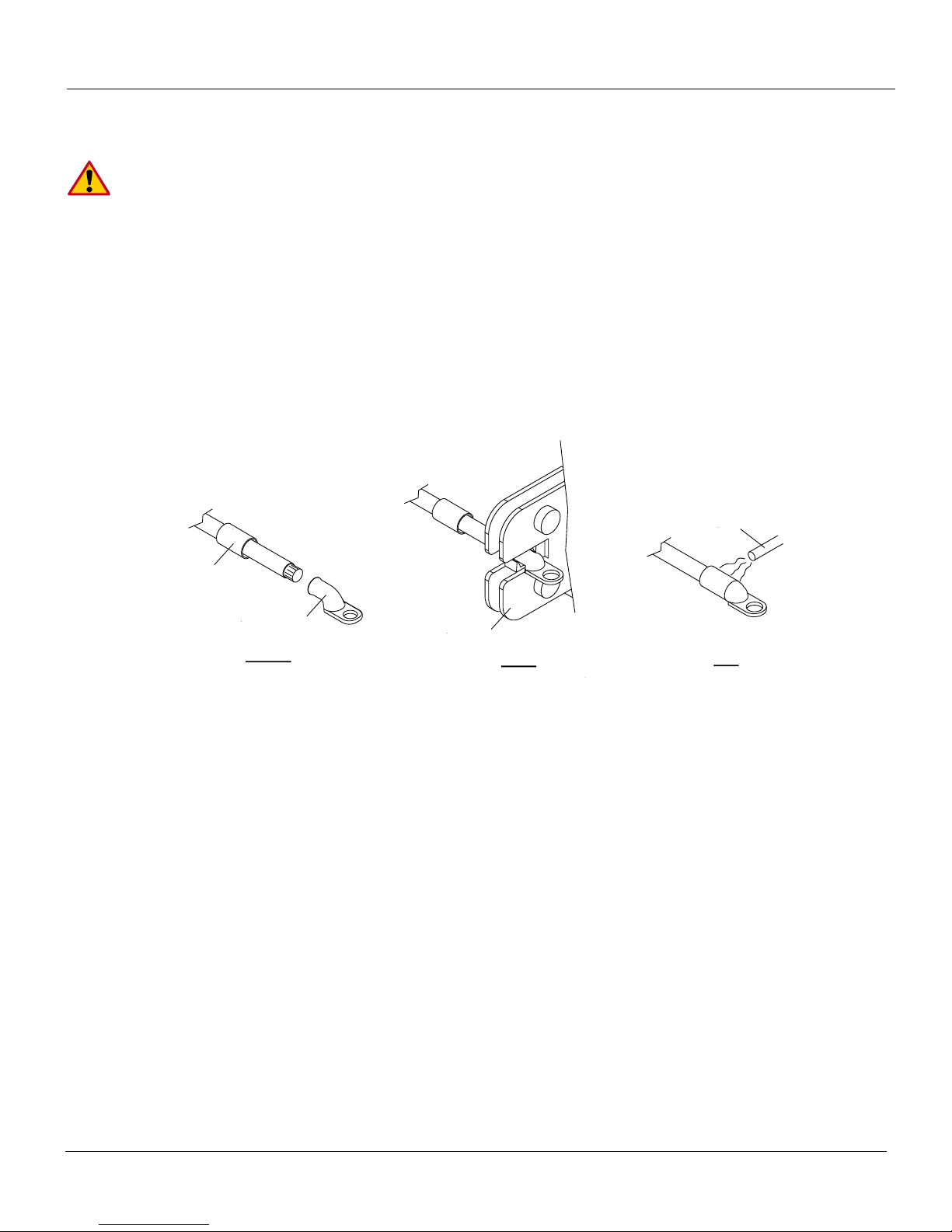
Prepare
Crimp
Seal
Heat Shrink
Battery Terminal
Crimp Tool
Heat Source
Wire Crimping 9.1
All grounding surfaces MUST be cleaned, prepped, and sealed per this manual. “Cut
to size” cables MUST be properly crimped and sealed as factory supplied. All connections
MUST be dressed with dielectric grease or equivalent sealer.
Battery Cable Crimping
1. Prepare the wire to be crimped. Straighten out the exposed copper wire and insert into the battery
terminal. Slide the provided heat shrink over the battery cable.
2. Use a crimping tool designed for crimping battery terminals for best results. The use of other tools to
crimp terminals could possibly damage the battery terminal and make poor connections between the
wire and terminals.
3. Slide the provided heat shrink over the battery terminal and cable to seal the connection.
Rev 1.1 37
Page 38
ILF 33/44/55 Installation Manual
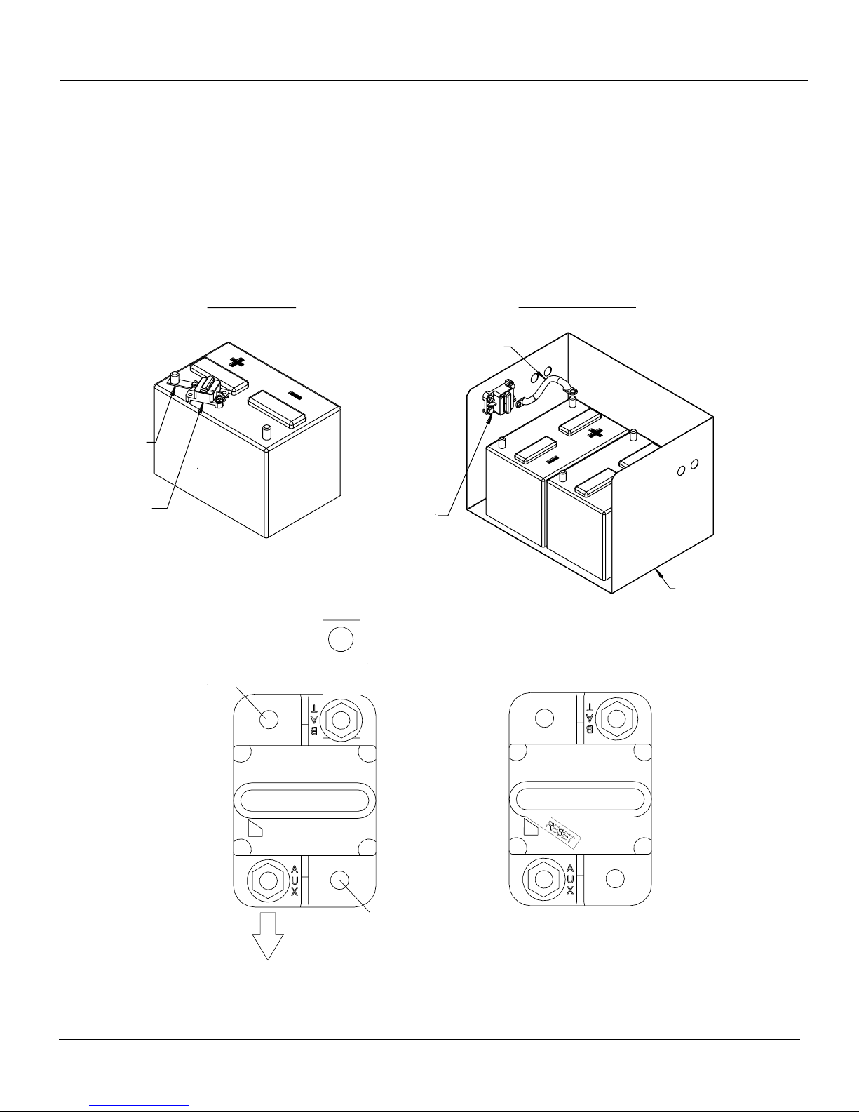
Circuit Breaker
Location
Circuit Breaker
Location
Battery
Box
Buss
Bar
Jumper
Battery Mount
Battery Box Mount
Buss Bar To
Positive (+)
Battery
Terminal
2 Gauge Cable
from Liftgate
Mounting
Hole
Mounting
Hole
Reset Required
Fig. 22
Fig. 21
Circuit Breaker Installation 9.2
1. Mount the circuit breaker securely in battery box or at positive battery terminal using the buss bar,
Fig. 21.
2. Connect the liftgate 2 Gauge cable to AUX stud on the circuit breaker.
3. Connect a 2 Gauge jumper from BAT stud on breaker to positive battery post if circuit breaker is not
mounted on battery. When circuit breaker is mounted on battery use the provided buss bar on the
“BAT” stud, Fig. 22.
Note: 150 amp minimum circuit breaker required.
Rev 1.1 38
Page 39
ILF 33/44/55 Installation Manual
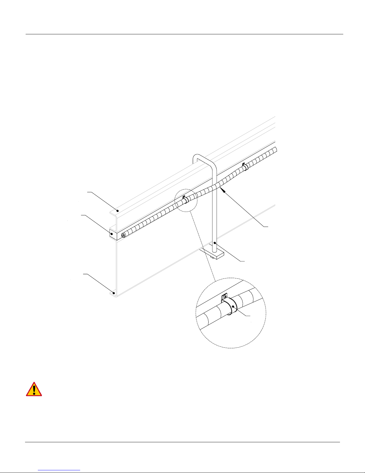
Body
Long
Sill
Wooden
Spacer(s)
Chassis
Frame
U-Bolt
Cable Routed
Outside of U-Bolts
Insulated
Cable
Clamps
Cable Routing 9.3
1. Route all cables along the wooden spacer and through the outside of the U-bolts.
2. Secure the routed wire every 12” with insulated wire clamps or staples against the wooded
spacer(s).
3. The use of wire loom is highly recommended to protect and facilitate cable routing. Wire loom not
supplied.
Inspect and test all electrical connections, wiring and the different functions to make sure
that the electrical installation is complete.
Rev 1.1 39
Page 40
ILF 33/44/55 Installation Manual
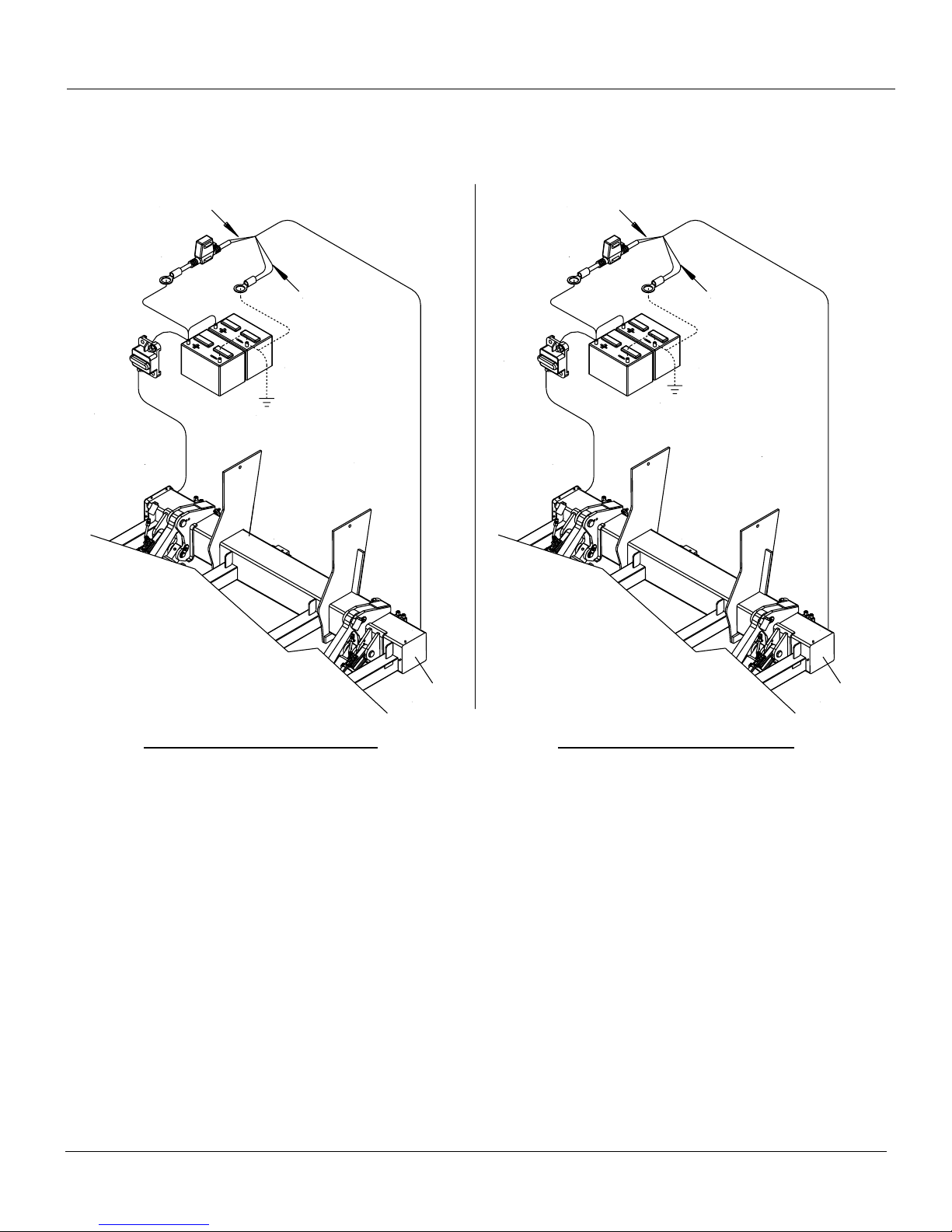
2GA. Liftgate
Power Cable
Aux.
Batteries
Liftgate
Mount Frame
Resetable
Circuit
Breaker
*In-Line
Fuse
Wires #2 and #4
go to postitive (+)
4-Conductor Control
Power Cable
from Control Board
***Ground
Wires #1 and Gr/Yl
go to ground (-)
Control Board
Location (Inside)
2GA. Liftgate
Power Cable
Main
Batteries
Liftgate
Mount Frame
**Resetable
Circuit
Breaker
*In-Line
Fuse
Wires #2 and #4
go to postitive (+)
4-Conductor Control
Power Cable
from Control Board
Wires #1 and Gr/Yl
go to ground (-)
Control Board
Location (Inside)
Ground
Main Power Connections 9.4
Battery Wiring Setup – Truck Battery Wiring Setup - Trailer
*In-Line ATC Fuse: 20 Amp. Replace with same amperage fuse when necessary.
**Resettable Circuit Breaker: 150 Amp Min. Replace with same amperage breaker when necessary.
***Ground: For optimal grounding, ground all batteries and power units to the body side rails of the vehicle.
NOTICE: DO NOT attempt to jump in-line fuses with other objects other than the specified fuse.
Do not increase the amperage rating of fuse. Serious harm to the liftgate will result when standard practices are not followed.
Rev 1.1 40
Page 41
ILF 33/44/55 Installation Manual
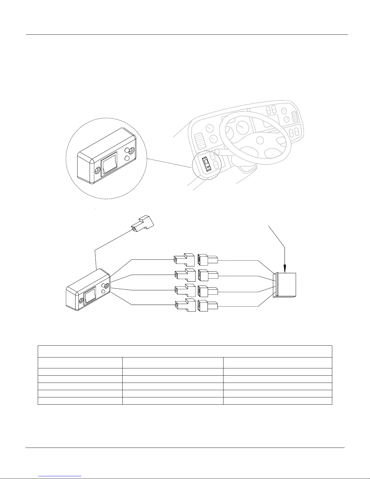
No Use
Blue #4
Black
Black
(-)Yellow/Green
Yellow/Green (-)
#2
#4
#1
Red #2
J11
Black
Blue (3)
White #1
J11 From
Control
Board
In-Cab ON/OFF Switch Wiring Table
Cable Number / Marking
Color
Function
1
White
Hot lead to red LED lights
-
Yellow/Green
Ground to LED lights
2
Red
12V Power from batteries
4
Blue
Control power to liftgate
3 (BS3)
Blue
Not Used
Fig. 23
On-Off Switch Installation (Truck Application) 9.5
1. Route the J11 wire harness from the control box to the inside of the cab.
2. Place the switch where it can conveniently be seen and reached from the driver’s seat as well as
from the ground, Fig. 23.
Rev 1.1 41
Page 42
ILF 33/44/55 Installation Manual
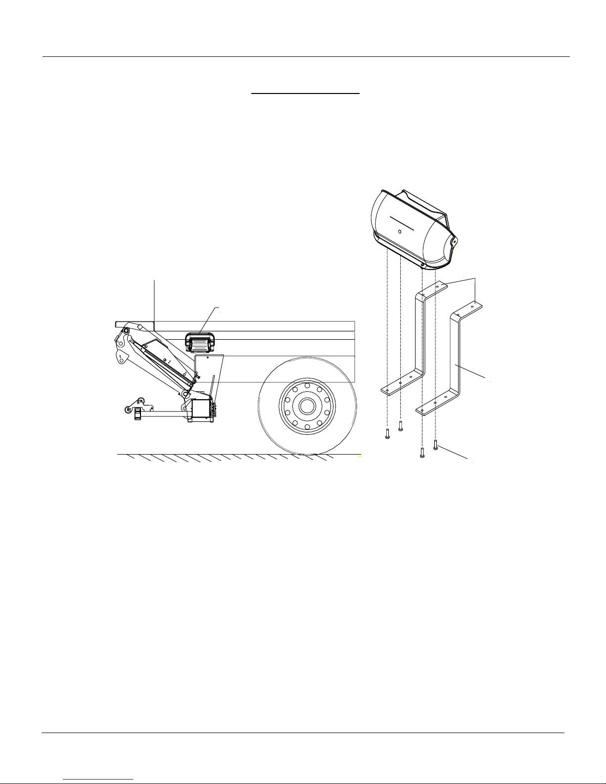
Bolt or Weld
to Body
Z-Brackets
Screws
Control Box
Location
Fig. 24
On-Off Switch Installation (Trailer Application) 9.6
1. Position the mounting brackets as close as possible to rear of the vehicle where the operator will
have a clear view of the platform/load, Fig. 24. Make sure the mounting brackets and control box do
not interfere with the platform and that the control box does not protrude beyond the width of the
vehicle body. Mount the provided Z-brackets to the vehicle by either bolting or welding the brackets
to the body.
2. Route the 4-wire cab switch cable together with the battery cable and the 4 wire harness for the
control power to the batteries along the sub-wood. Secure the cable every 12” against the sub-wood
with cable staples or insulated wire clamps. Make sure the cable is kept away from sharp edges and
moving parts to prevent any damage.
Rev 1.1 42
Page 43
ILF 33/44/55 Installation Manual
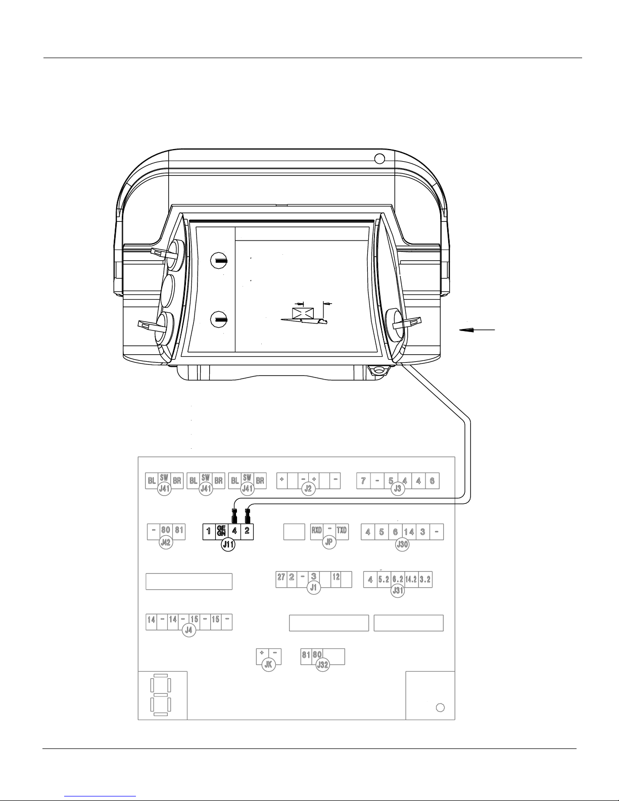
Power LED
Unplug exsiting J11 connector from board
Install 2 Position Toggle Switch in Control Box Face
Run leads from Toggle Switch to #2 & #4 on Circuit Board
Use Tie Straps to hold unused J11 Connector in safe location
On-Off-Switch
Tilt
Lift
Up
Down
Up
Down
OPERATING INSTRUCTIONS
For questions regarding operation call (888) 774-5844
ILF 33/44/55
• To operate this liftgate read and understand the operating decals
and manuals.
• Make certain the platform is clear before operating the liftgate.
• Liftgate shut-off switch must be turned off when liftgate is not
in use.
• Keep platform in horizontal position when loading and unloading.
• Do not overload, refer to capacity decals.
Max Capacity
on Platform
Load
24"
ON/OFF Switch Wiring
On a trailer installation the control port J11 has to be connected with an on/off toggle switch connecting
2 and 4 on port J11 together. NOTE: The Circuit Board is located inside the 7” x 7” mount tube of
the liftgate assembly on the curb side.
Rev 1.1 43
Page 44
ILF 33/44/55 Installation Manual
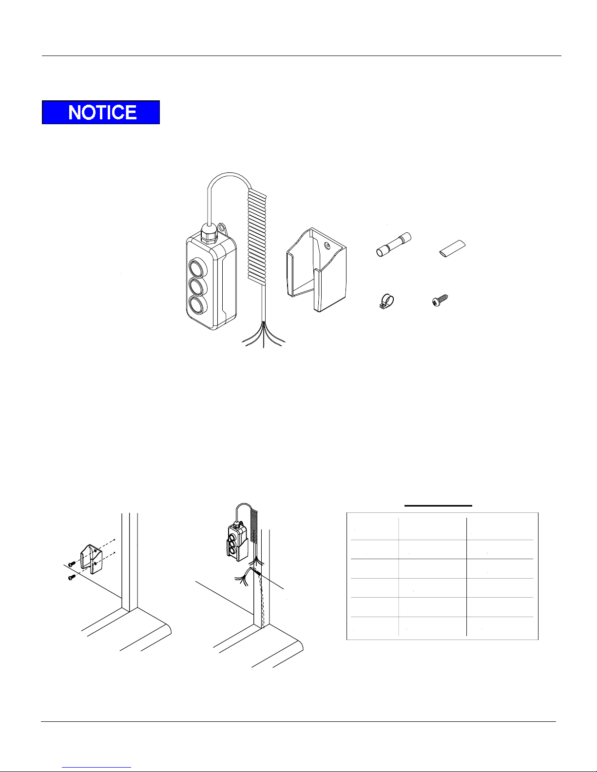
3-Button
Hand Held Remote
Hand Held Remote
Holster
Butt Splice
Heat Shrink
Cable Clamp
Holster Screws
Secure liftgate wire
with wire clamp at
entry point
Bed Extension
Floor
Sill
Corner Post
Function
Wires From
Control/Color
Wires From
Liftgate/Number
Up
Down
12V (Hot)
Tilt Up
Tilt Down
5.2 / Yellow
6.2 / Brown
4.3 / Red
3.2 / White
14.2 / Green
5.2 / #4
6.3 / #3
4 / Green-Yellow
3.2 / #1
14.2 / #2
Wiring Table
Bed Extension
Floor
Sill
Fig. 25
Fig. 26
Remote Hand Control Installation 9.7
Hand Controls are NOT weatherproof and are to be stored inside the vehicles body in holster or in
weatherproof box (optional). For “Reefer” and Flatbed installations, a “plug & socket” installation is
recommended.
Hand Held Remote and Holster Installation:
Reminder: It is recommended to install the holster inside the body of the vehicle on the rear curb
side.
1. Mount the holster approximately 40”- 48” from the vehicle floor, or determine the best location as
preferred by end user, Fig 25.
2. Route the cable from the liftgate up through the inside corner post or between the wall extrusions of
the truck. Use the wire clamp to secure the incoming cable to the surface, Fig. 26.
3. Splice the cables from the liftgate to the hand held remote with the supplied butt connectors and seal
all connections with heat shrink. Use the Wiring Table to splice the wires.
Rev 1.1 44
Page 45
ILF 33/44/55 Installation Manual
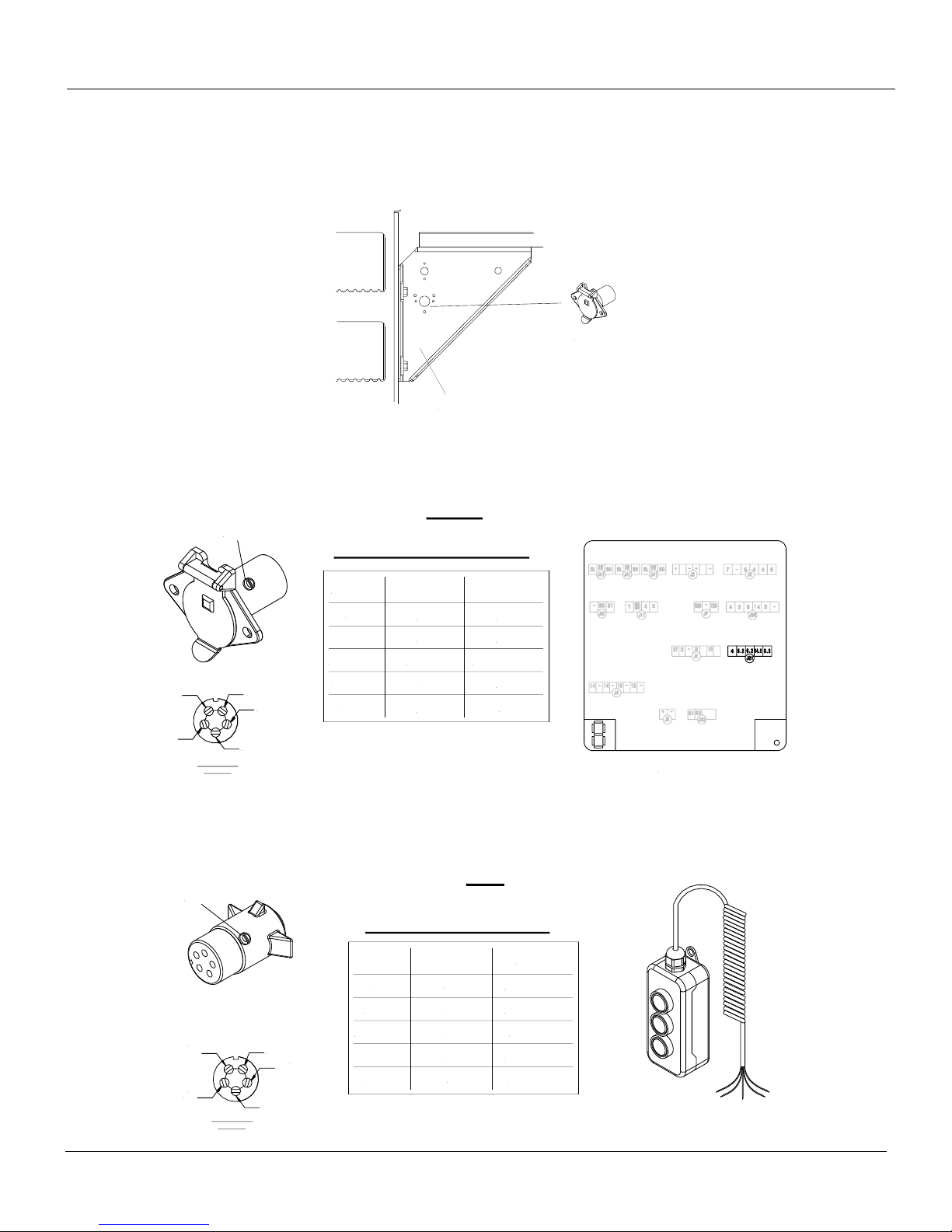
Strut
Socket
Power LED
#3
Green/Yellow
#2
#5
#1
Function
Socket
Up
Down
12V (Hot)
Tilt Up
Tilt Down
5.2
6.3
Green/Yellow
3.2
14.2
#4
#3
Green
#1
#2
Socket to Control Wiring Table
Control
Board
Socket
Wiring Terminal
Rear View
Control Board
Socket
Set Screw
#1
#2
#3
Wiring Terminal
Rear View
Plug
Yellow
#4
Red
Brown
Green
White
#5
Function
Plug
Up
Down
12V (Hot)
Tilt Up
Tilt Down
5.2 / Yellow
6.2 / Brown
4.3 / Red
3.2 / White
14.2 / Green
#5
#3
#4
#1
#2
Plug to Control Wiring Table
Remote
Plug
Hand Held Remote
Set Screw
Plug and Socket Installation for Reefer or Flatbed Trucks (Optional):
3. The socket can be installed in varies locations depending on user preference. The dock bumper
strut has pre-drilled holes for the socket to mount, or it can also be installed where the end user feels
most convenient.
4. Wire the female socket to the control board. Remove the set screw and push out the wiring terminal
from inside the socket housing. Feed the wire from the control board through the back of empty
socket housing. Wire socket as indicated in the Socket to Control wiring table.
5. Wire the male plug to the hand held remote. Remove the set screw and push out the wiring terminal
from inside the plug housing. Feed the wire from the control board through the back of the empty
plug housing. Wire plug as indicated in the Plug to Control wiring table. Assure the number matches
the female terminal wiring.
Rev 1.1 45
Page 46
ILF 33/44/55 Installation Manual
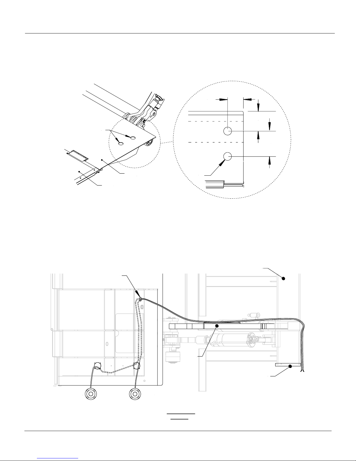
6-3/4""
10-1/2"
10"
2X
ø2"
Front of Platform
Steel Main
Section
Tip Section
Drill
Mount Tube
Control Board
(Inside Tube)
Lift Arm
w/Bar
Cable
Cover
Location
Rear
Foot
Control
Front
Foot
Control
Platform Main
Top View
Foot Control Installation (Optional) 9.8
1. Measure and drill two ø2” holes on the main section of the platform (curb side). Use the dimensions
shown below.
2. Mark or label each foot control harness to avoid confusion after the harnesses have been routed.
The platform main is designed with pre-drilled holes underneath for routing each harness. Feed
each cable harness through each foot control slot on the main section of the platform and route each
harness as shown below. Remove the cable cover to pull routed cable out of the platform. Once the
cable is out of the platform, the lift arm is equipped with a bar that serves as a guide for the
harnesses to be routed along and secured to. Next, secure each foot control module with the
provided screws on the platform.
Rev 1.1 46
Page 47
ILF 33/44/55 Installation Manual
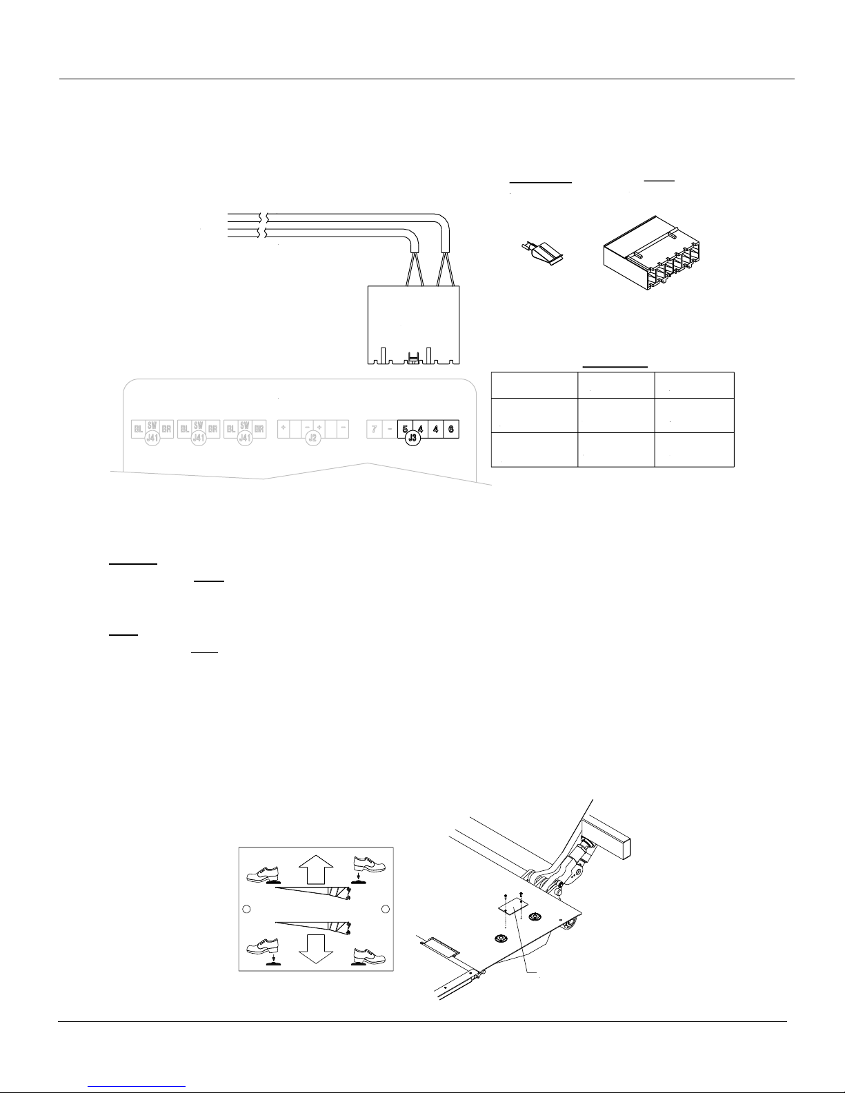
Rear Foot
Control Harness
Control Board
Rear Foot Control Harness
Front Foot Control Harness
From
Platform
Pin/Color
Wiring Table
4 (Hot)/Blue
4 (Hot)/Blue
5 /Brown
6 /Brown
Pin/Color
Front Foot
Control Harness
J3 Plug
Crimp Terminal
P/N: 1358765
J3 Plug
P/N: P-1358710
Operation Plate
When routing the cable, make sure to allow cable slack to prevent any damage to the cable(s).
3. Use crimp terminals on the end of the wires. Insert the Front Foot Control Harness wires to pins 5, 4
on the J3 plug. Connect Rear Foot Control Harness to pins 4, 6 on J3 plug.
4. Test functionality of each foot control. Follow the steps below:
DOWN
Step on the front foot control and hold – wait between one to three seconds before you step on the
rear foot control.
UP:
Step on the rear foot control and hold – wait between one to three seconds before you step on the
front foot control.
IF BOTH SWITCHES ARE NOT ACTIVATED BETWEEN ONE TO THREE SECONDS, START
OVER.
5. Once operation has been verified, check all connections and verify that all screws are properly
fastened. Finally, install the operation plate and make sure the arrows on the plate match the foot
control operations.
Rev 1.1 47
Page 48
ILF 33/44/55 Installation Manual
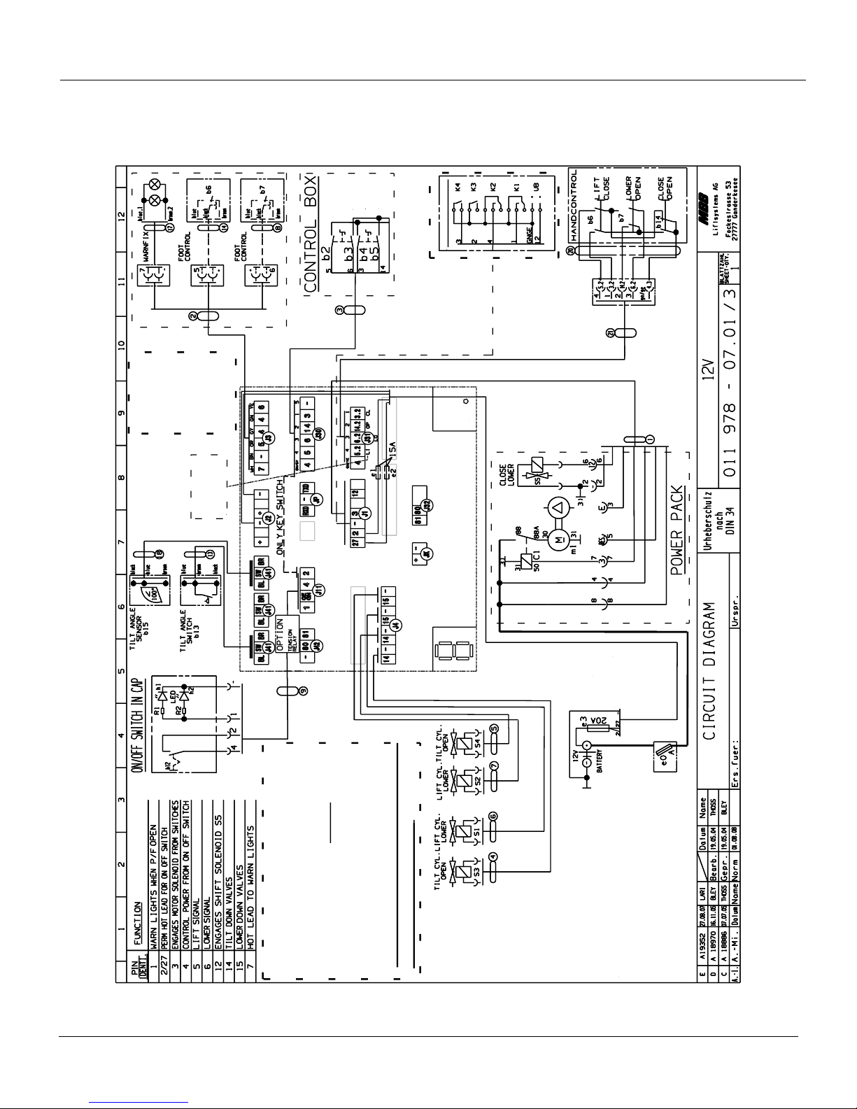
150
# 2 BLACK
# 4 BLACK
# 1 BLACK
GREEN / YELLOW
(+)
(-)
ILF 33/44/55 PLUS
CIRCUIT BOARD
OPEN
WIRELESS HANDCONTROL
OPTIONAL
Legend
:
gn : green
bl : blue
br : brown
wt : white
ye : yellow
sw / bk : black
gy : green-yellow
LI : Lift Up
LO : Lower Down
OP : Open Gate
CL : Close Gate
* Good voltage is the most important first step
in troubleshooting the litgate.
* Test voltage at the J11connection
between wire 4 and ground (min. 10 V).
* When testing for electricity on the individual
solenoid plug at the cylinder, always test voltage
between the two prongs on the plug itself.(min. 7 V)
* After troubleshooting, carefully close the rubber cap
and secure it with the plastic strap
.
CLOSE
LOWER
LIFT
HACKBARTH
* When testing the voltage on different
locations, always ground on plug J1.
Tilt - Up bypass -- J11 #4 min. 8.5 V
Power
LED
Electrical Schematic 9.9
Rev 1.1 48
Electrical Schematic
Page 49
ILF 33/44/55 Installation Manual
B13 LIFT ARM
FOOT
CONTROL
WARNING
LIGHTS
CAB CUT OFF SWITCH
CONTROL
BOX
HAND
REMOTE
POWER PACK
GROUND for PC BOARD
(green/yellow and black # 1)
POSITIVE for PC BOARD
(black #2 to 2
and black # 4 to 27)
CYLINDERS
LIFT 15 (2 ea)
TILT 14 (2 ea)
BL - Blue
BR - Brown
SW - Black
GE - Yellow
GN - Green
- Negative
+ Positive
AUX port
Power LED
B15 PLATFORM
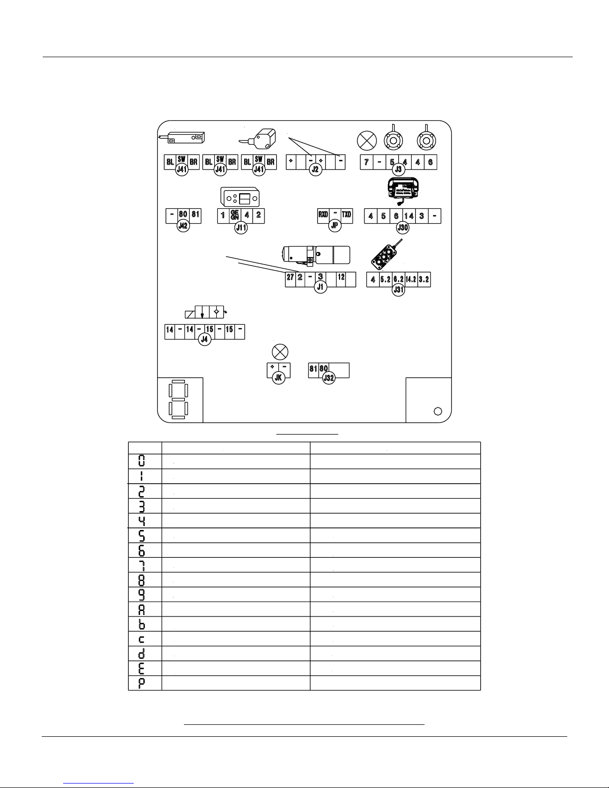
Control Board Codes:
System ok / Cab switch off, (or missing bridge J11/2<->4)
System ok / Cab switch on, (or bridge J11/2<->4)
Low Voltage
Missing tilt switch B-13 at lift arm or defective.
Missing tilt angle sensor B-15 at lift platform or defective
Missing tilt angle sensor B-15 at platform or defective
Warning lights shorted
Short in cab switch/on-off switch or aux port
General short in electrical wiring
Emergency program (all sensors are bypassed).
Activation by: Press Open+Lower>10 seconds
Diagnosis mode activated
Defect at motor solenoid detected during lifting
Voltage V02 (J1 pin 2) is missing, defective fuse
Defect at opening, valve (S3/S4) or motor relay
detected during opening
S5 valve detected during closing or motor solenoid defective
S5 valve detected or defect at lowering valve (S1/S2)
Cab switch: off/on (or disconnect bridge J11/2<->4)
Automatically when the valves are back to normal
Automatically when the valves are back to normal
Automatically when the valves are back to normal
Cab switch: off/on (or disconnect bridge J11/2<->4) or close
tail lift
Cab switch: off/on (or disconnect bridge J11/2<->4) or close
tail lift
Cab switch: off/on (or disconnect bridge J11/2<->4) or
voltage interruption MBB control
Cab switch: off/on (or disconnect bridge J11/2<->4)
Automatically when the valves are back to normal
Replace the fuse
Automatically when the valves are back to normal
Automatically when the valves are back to normal
Automatically when the valves are back to normal
Removing service connector
Code
Description
Reset
Control Board Codes 9.10
Rev 1.1 49
Electrical Wiring, Components Overview, and System Codes
Page 50
ILF 33/44/55 Installation Manual
6 PLCS
6 PLCS
IN
IN
OUT
IN
OUT
IN
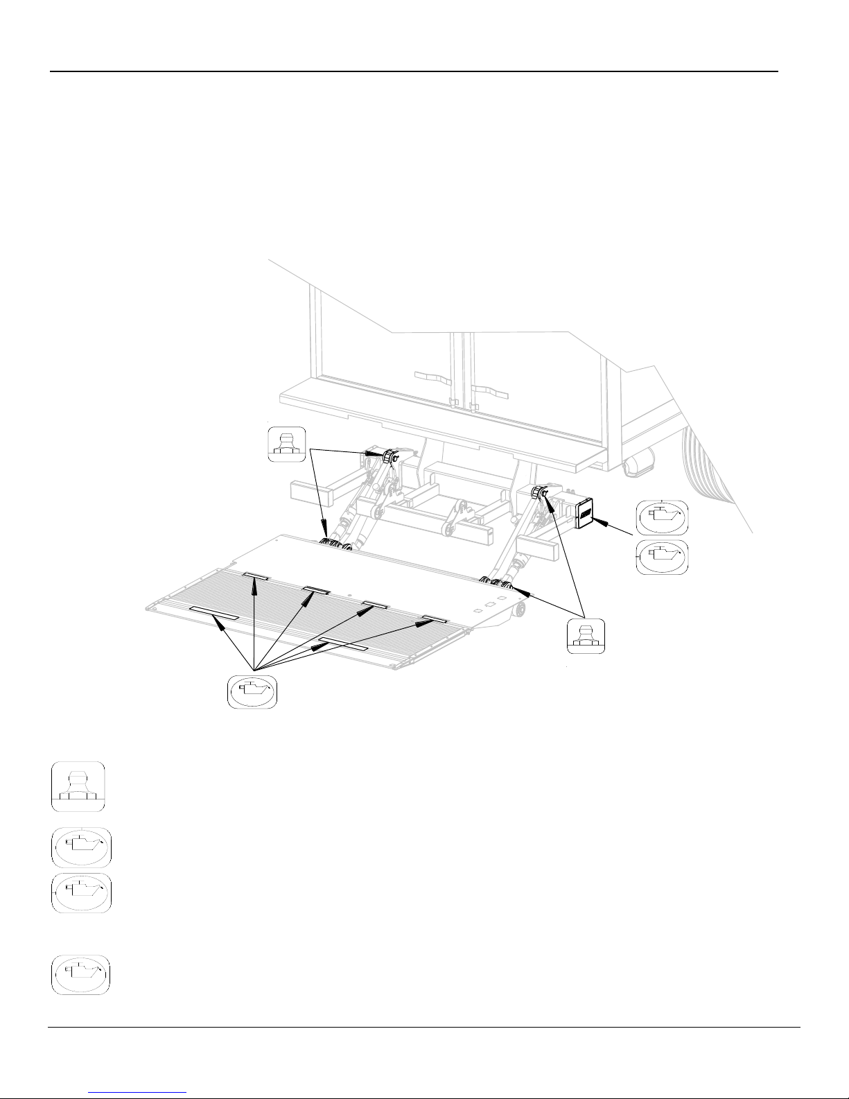
10 Lubrication
1. Lower the platform to the ground.
2. Remove red protector caps from each component. Lubricate, grease, and oil per diagram below.
3. Cycle platform up and down several times. Lubricate and grease all points again.
4. Wipe any excess grease and replace all red protector caps on zerks.
Zerk Fitting – 12 places, (3 in the mount frame, 3 in the cylinder/platform area).
Oil level in the power pack tank (see marking inside of power pack reservoir).
Platform hinges and optional cart stops (use WD-40 lubricant or equivalent).
Rev 1.1 50
Page 51
ILF 33/44/55 Installation Manual
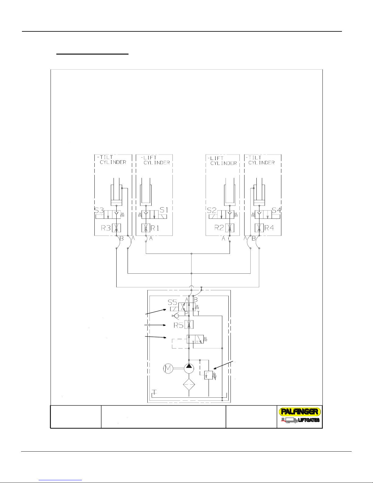
Hydraulic Schematic
4 cylinder gate (2 lift & 2 tilt cylinder)
Functions:
Lift: M+S1+S2
Lower: S1+S2+S5
Tilt Up: M+S5
Tilt Down: S3+S4
Horiz. Open: M+S3+S4
Pressure Relief
2850 PSI
200 bar
Shift Valve S5
Restrictor Valve R5
Flow Divider
I
I
Functions:
S1 and S2 = Release Valve for lowering function
S3 and S4 = Release Valve for tilt down function
R1 and R2 = Flow Restrictor located inside hose adaptor on lift cylinder
R3 and R4 = Flow Restrictor located inside hose adaptor on tilt cylinder
S5 = Shift Valve is activated on tilt up and lowering function
R5 = Restrictor Valve located in power pack
Flow Divider is activated, when fluid is going back into the power pack
If Flow Divider is loose or hanging up the fluid is circulated back in to tank
15939 Piuma Ave. Cerritos, CA 90703
11 Hydraulic Schematic
Rev 1.1 51
Page 52
ILF 33/44/55 Installation Manual
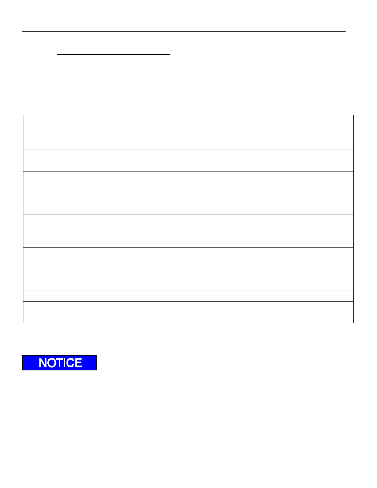
Decal Kit
Decal
Qty.
Part No.
Description
A 1 ATG-URGWA
Urgent Warning: Elevating gate instructions
B 1 ATG-BKR
Circuit Breaker Reset (must be placed where the circuit
breaker was installed)
C 2 ATG-XXXX
Capacity (please check the serial number plate to find out your
specific capacity)
D 1 ATG-RESET
Circuit Breaker Protection
E 2 ATG-WLH
Warning: liftgate can crush
F 2 ATG-CTN
Caution: Always stand clear of platform area
G 1 ATG-CAB
Liftgate Shut-Off (Place Decal next to the On-Off Switch in the
Cab)
H 1 ATG-WNG
Warning: Use handle to open (Must be located underneath
handle (main section)
I 1 ATG-FT
Notice for Foot Control
J
Strip
Conspicuity Tape (Place tape along bumper)
K 1 ATG-ILF
Operating Instructions (Place in control box)
L 1 85-0816-000*
Operating Instructions (Place on the curb side of vehicle body
above control box)
12 Decal Placement and Inspection
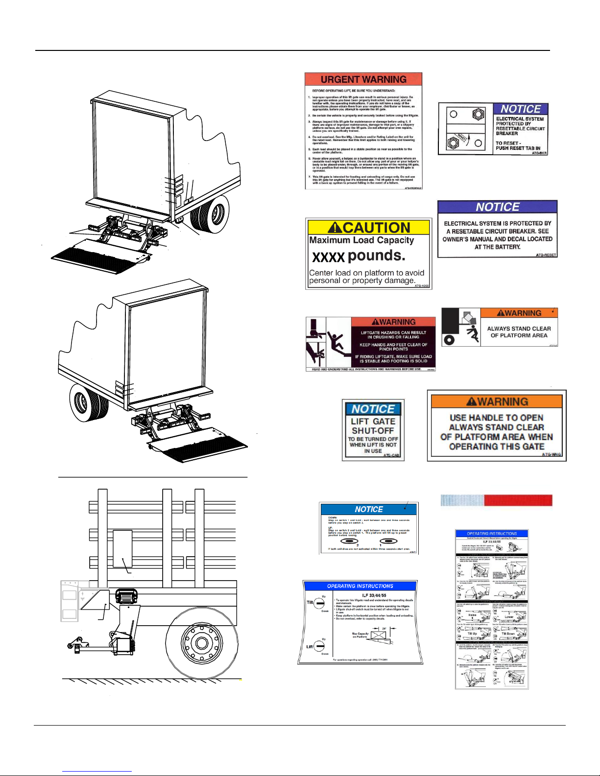
For operator safety, all decals appearing in “Decal Kit” must be in a conspicuous place on control side of
liftgate. This is typically a combination of decals on the liftgate and truck or trailer body. Please make sure to
place the maximum capacity decal (C) on driver and curb side.
Important: Never remove or paint over any decal. If any decals below require replacement contact
Palfinger Liftgates.
*Stake and Flatbed Vehicles: It is recommended to install a plate on the stakes of the vehicle to serve as a
surface to install Decal L. Part number 60-0115-200 maybe used for flatbed vehicles with no stakes. Fig. 27.
It is the installer„s responsibility to determine the proper application of the Conspicuity tape (J), and to
ensure that the vehicle meets DOT and federal lighting regulations. Keep in mind that there are
different requirements depending on the classification of the vehicle. This document is not intended to
replace published agency regulations, and it is strongly recommended that the installer references the
Code of Federal Regulations (CFR) which can be viewed at http://www.ecfr.gov.
Rev 1.1 52
Page 53
ILF 33/44/55 Installation Manual
Driver
Side
Curb
Side
A
F
C
E
D
I
H
J
J
F
C
E
G, K
L
Flatbed Vehicle (Curb Side)
Plate
60-0115-200
Plate
Decal - B
Decal - A
Decal - D
Decal - H
Decal - I
Decal - J
Decal - E
Decal - F
Decal - G
Decal - C
Decal - K
Decal - L
Fig. 27
Rev 1.1 53
Page 54

ILF 33/44/55 Installation Manual
13 Final Inspection Check List
Liftgate failure or malfunction could result in property damage, personal injury or death if you fail to
check each of the following items listed. DO NOT USE the liftgate if any of the following points are
NOT verified and checked.
Installation is NOT complete and all WARRANTIES are VOID if you have not checked and verified all
items listed on this inspection sheet. Inspection sheet is to be filed at the facility where liftgate was
installed.
Structural Inspection
All welds are 100% complete per this manual.
All nuts, bolts, mounting hardware, pins, chain anchors are tight.
All mounting dimensions are correct and liftgate is square and parallel per this manual.
Capped frame cutout with flat bar or angle.
Hydraulic Inspection
Pump reservoir is filled to 1.5" from top when cylinders are completly compressed (platform is resting on the ground).
Hydraulic components and connections do not leak.
(Should be checked after unit is hydraulically locked for five (5) minutes.)
All hydraulic lines are secured with cable ties, hoses clamps, or other fasteners. No hoses or components rub on the
frame, platform, or any other components while unit is in operation or in storage. No hoses are kinked or bent.
Electrical Inspection
Battery cable(s) attached and clamped tight and dielectric grease is used to seal all connections.
All electrical lines are secured with cable ties, hoses clamps, or other fasteners and are properly protected.
Circuit Breakers installed and wired per instructions.
Lights wired properly and operate per DOT, State, and Federal requirements.
All connectors at the control board are properly connected to their corresponding ports.
Measured battery voltages: Flooded Batteries = 12.6V; AGM Batteries = 12.8V.
Operational Inspection
All decals are in place and legible per instructions.
All pivot points are lubricated per instructions, and Zerk fittings have been capped.
Up stops are in place. Wheel is set for proper opening when lowering. Snubber pads are tight against platform.
Platform travels up and down smoothly and freely, without any hesitation or unusual noises.
Platform is flush with the bed extension, tip is pitched approximately 2“-2.5“ above rear bed extension when raised
completely.
Platform rests on the ground when tilted via the operational control.
Platform raises and lowers properly and at correct speed. (2 to 4 inches per second)
Gate is painted, body is clean around gate. Cylinders are clean and rubber & plastic caps are in place.
The liftgate serial number and model number are documented on the inside of the front cover of the Owners Manual,
as well as the installation manual in the space provided.
Owners Manual is in the vehicle's glove box.
Supervisor has demonstrated the instructions in the Owners Manual to the customer/driver upon delivery.
Inspection Information:
Name (please print): ____________________________________________________________
Completed by: _________________________________________________________________
Title: ______________________________________________ Date: ______________________.
(Signature)
Rev 1.1 54
Page 55

ILF 33/44/55 Installation Manual
Rev 1.1 55
 Loading...