

Paladin Tools 1112 AM Operation And Use Manual

Support: 1.800.272.8665
Int’l Phone: 001.804.550.1121
E-Mail: paladin@paladin-tools.com
Web: www.paladin-tools.com
Tool Operation and Use Guide
Paladin Tools
®
1
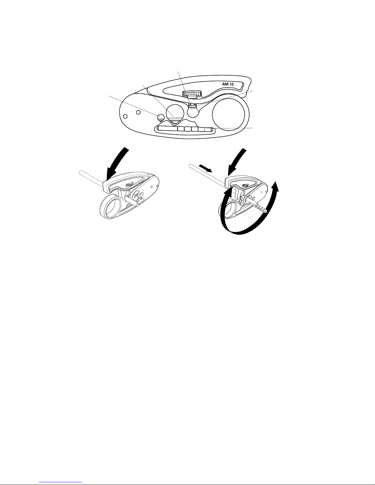
1112 AM 12 Twisted Pair Cable
Stripper
To cut cable:
1. Install the wire or cable into the circular hole
closest to the finger loop.
2. Grip the tool & squeeze the top handle down until
the cable is cut.
To strip wire & cable:
1. Adjust the blade depth screw to the desired cutting
depth.
2. Place wire/cable into the smallest hole it can fit
into.
3. Put your finger into the finger loop & spin the tool
clockwise around the cable 3 to 6 times. Do not
squeeze the top handle down when spinning.
4. Open the handle & remove the cable. Pull the
stripped insulation off the cable.
Note: The AM 12 is especially useful for 4-pair UTP
& STP cables.
Cutting cable
Stripping cable
Blade depth
adjustment screw
Stripping length
gauge
Strip/cut up to 12 AWG (0.1” diameter)
Strip/cut up to
0.5” diameter
Strip/cut up to
0.2” diameter

Tool Operation and Use Guide
2
Blade Depth Adjustment Screw
Round Cable
Stripper
Cable
Cutter
1116 Data SureStrip™ Twisted Pair
Cable Stripper
To cut wire & cable:
1. Install the wire or cable into the cable cutter section.
2. Grip the tool & squeeze the top handle down until
the article is cut.
To strip round wire & cable:
1. Adjust the blade depth screw to set the blade cut
depth to desired level to ensure a non-scoring strip.
This may take several test settings before achieving
optimum depth.
2. Place wire/cable into the center round hole of the
tool.
3. Place your finger into the finger loop & spin the
tool clockwise around the cable 3 to 6 times. Do
not press down on the top lever. The tool has a
self-regulating spring to control stripping.
4. Open the tool & remove the cable. Pull the stripped
insulation off the cable.
To strip flat satin telephone cable:
1. Place cable into the flat cable stripper area located
at the front of the tool.
2. Close the tool & hold tool in palm or one hand, &
hold the cable steady in other hand.
3. Using a straight, no-angled motion, pull the tool
away & off from the end of the cable. This will strip
off the outer jacket exposing the inner conductors.
Perfect for 25-Pair!
Flat Cable
Stripper
Paladin Tools
®
3
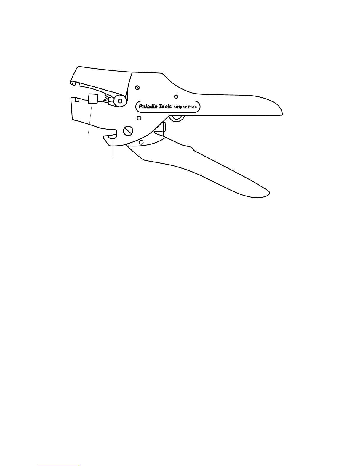
1113 pictured
To cut wire:
1. Place the wire in the cutting slot located in the
bottom handle.
2. Squeeze the handles to close the cutting blade.
To strip wire:
1. Adjust the orange wire stop located in the jaws of
the tool to the desired strip length. Squeeze the
sides of the stop & slide to the proper length. Use
the metric ruler on the side of the tool as a guide
for the length.
2. Adjust the top slider for the proper insulation thick-
ness of the wire. Position the button fully forward
for thicker insulation & fully backward for thinner
insulation.
3. Insert the wire into the front of the jaws. Make
sure the end of the wire is flush against the front
edge of the wire stop.
4. Squeeze the handles to close the jaws & engage
the stripping blades.
Note: Not for use on Teflon or Kapton insulated wire
1113 & 1114 stripax® Pro Wire
Strippers
Wire stop
Cutting slot
Tool Operation and Use Guide
4
Paladin Tools
®
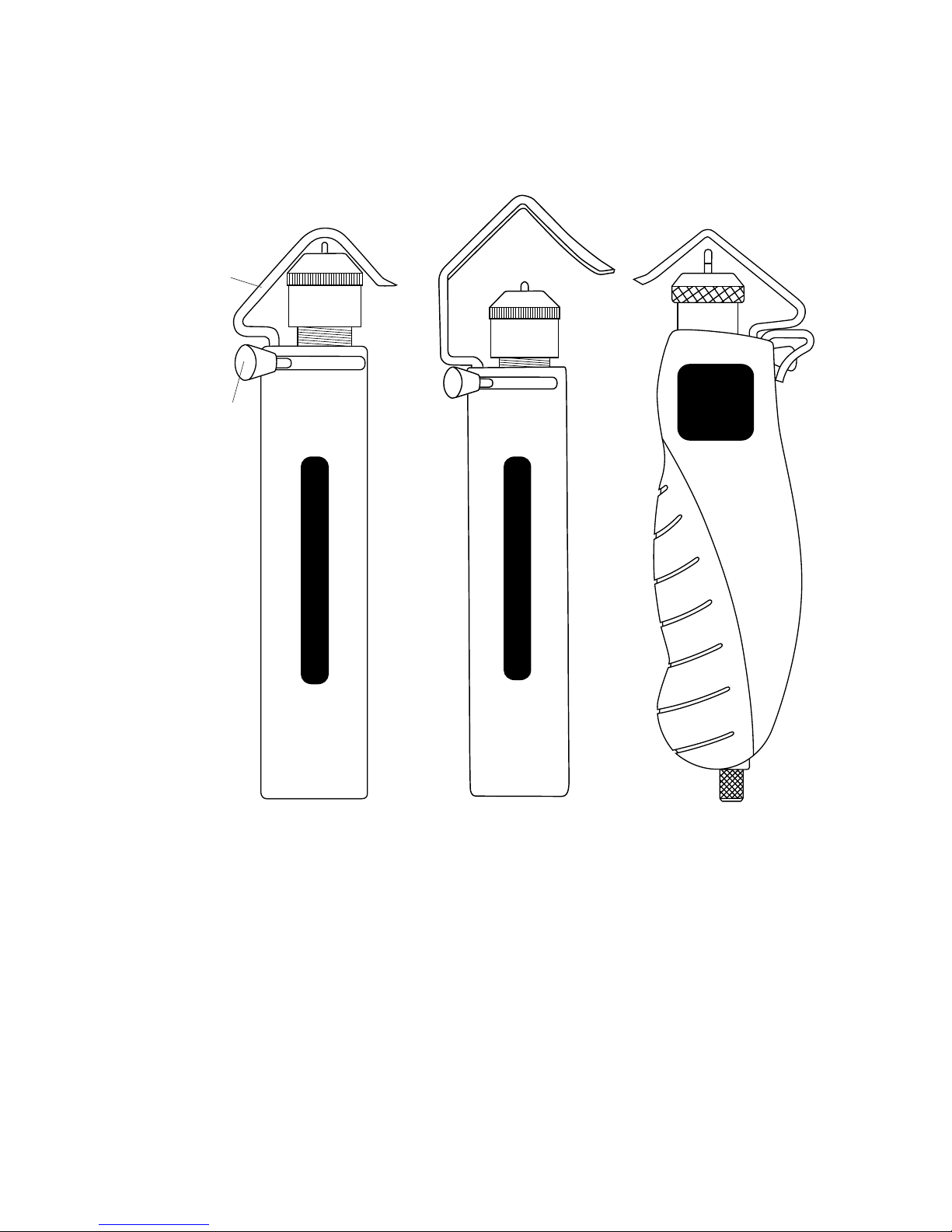
AM 25
1820
Paladin
Tools
®
1822
1820 Series Cable Strippers/Slitters
Operating instructions:
1. Rotate the silver blade head in clockwise or counterclockwise directions to decrease or increase the
blade cutting depth respectively. (For 1822, rotate
bottom knob to set cable diameter)
2. Lift the spring-loaded retaining clamp & install the
cable. Release the clamp to allow the clamp to hold
the cable in place.
(cont’d on page 5)
Retaining
clamp
system
Springloaded
blade
direction
trigger
Paladin Tools
®
AM 35
1821

Paladin Tools
®
5
3. For circular slitting, rotate the tool clockwise about
the cable until adequate penetration of the insulation is achieved.
4. For longitudinal slitting, push & hold the trigger to
the right & slide the tool down the length of the
cable.
5. For spiral slitting, push & hold the trigger in the
center & rotate the tool down the length of the
cable. This creates a “corkscrew”-type slit. Remove
the tool from the cable.
6. After cable is slit, remove the insulation by pressing
the pointed end of the cable clamp into the groove
& pulling the insulation away. Peel off the remaining
loose insulation.
To replace blades:
1. Lift the cable clamp up.
2. Unscrew the silver head.
3. Remove spring, blade & washer.
4. Remove washer from “old” blade.
5. Spare blade is in handle. Remove cap from bottom
corner to access. (For 1822, spare blades on side
of handle)
6. Replace cap.
7. Slip washer over blade.
8. Install new blade/washer & then replace spring.
9. Screw silver head back on.
Tool Operation and Use Guide
6
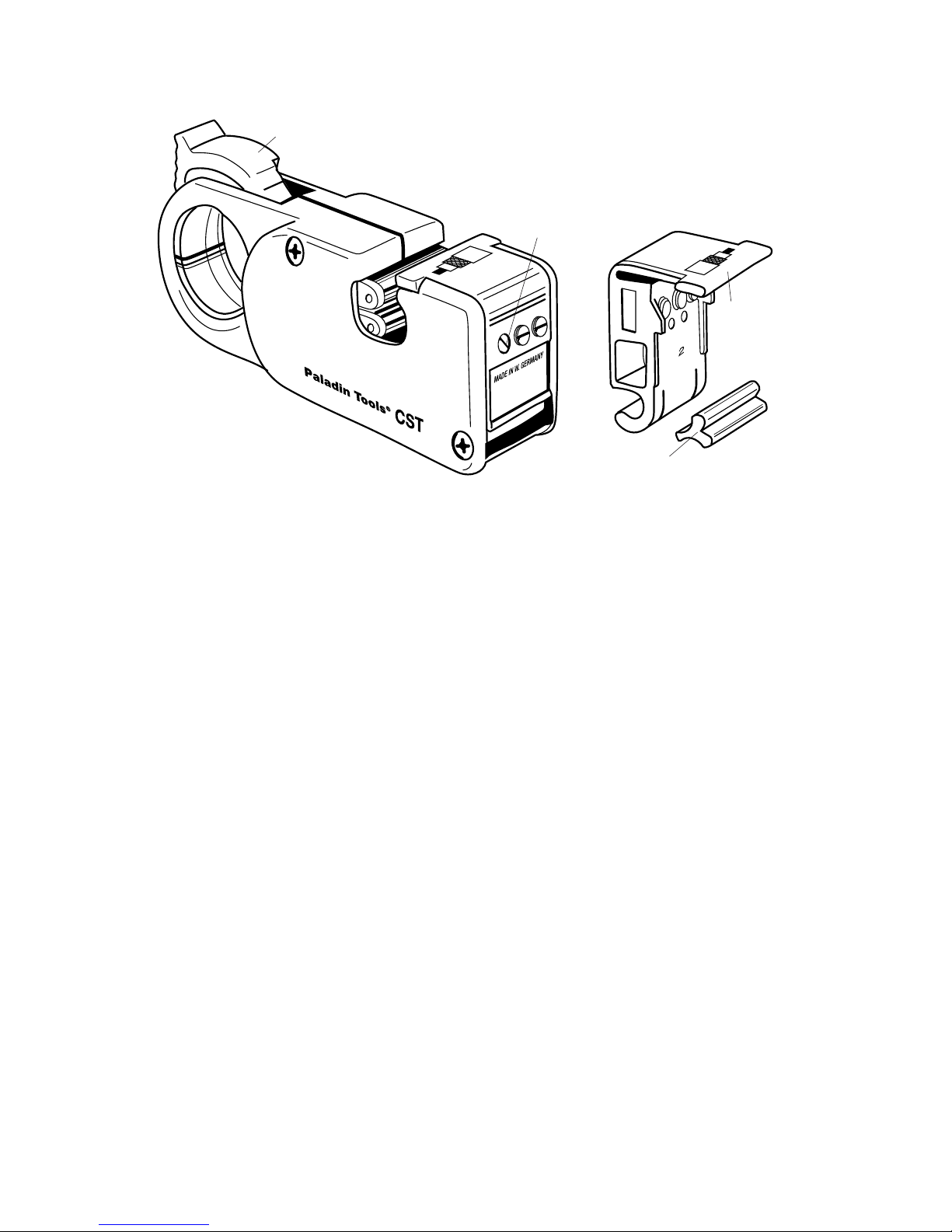
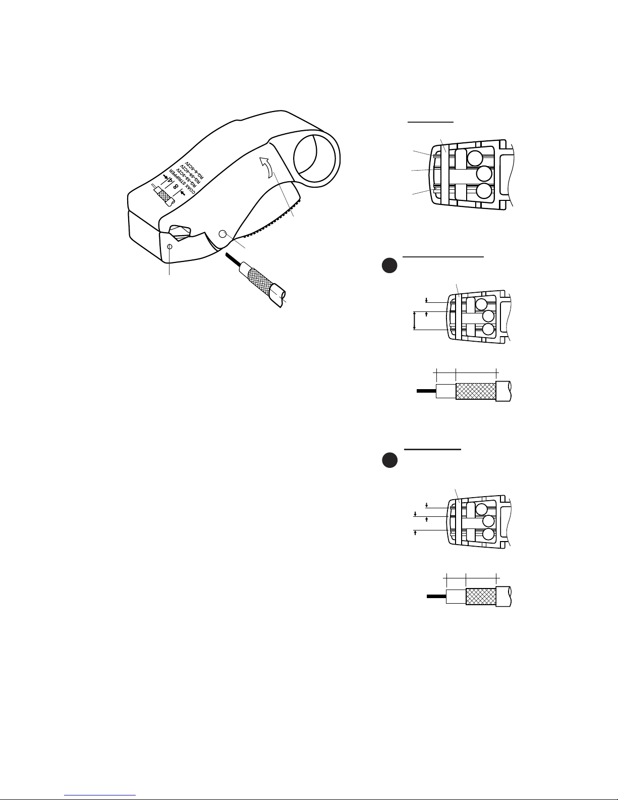
1240 Series CST (Coax) Strippers
To strip coaxial cable:
1. Make sure the blade cassette is installed in the
back section of the tool.
2. Fully retract the rollers by moving the cam switch
lever to the full, back position.
3. Push the locking slide on the bottom to the fully
advanced position.
4. Insert the cable into the side of the tool where the
arrow indicates.
5. Push the cam switch lever to the fully forward
position to lock the cable in place. Pull the locking
slide on bottom of tool back to set the cam.
6. Adjust the screws located on the back side of the
tool to position the blade cutting depths for each
stripping level (jacket, shield, inner dielectric
insulation).
7. Place your finger in the round hole & rotate the
tool around the cable clockwise in the direction of
the arrow.
8. Hold the cable with one hand & pull the tool out
away from the cable to strip.
9. Repeat the above steps until the proper cutting
depth is achieved.
Cam
Y-block
Adjustment
screws
Memory
cassette
Paladin Tools
®
7
To strip coaxial cable:
1. Set up blade strip lengths to
Option “A” or “B” by removing the
retaining pin from the bottom jaw.
Move the blades to the desired strip
length channels. For 2-level strip,
remove center blade. Re-insert the
retaining pin.
2. Adjust blade depth using the hex
key to turn the hex screws in
bottom jaw for each blade.
3. Test strip. Install cable in front of
tool in direction of graphic. Rotate
tool clockwise 6 times around cable.
Remove tool from cable and remove
stripped layers with fingers.
4. Repeat set-up of strip length &/or
depth until desired strip is achieved.
Notes:
1. The 1257 is preset for standard RG6 CATV “F” cable.
See step 2 above to adjust blades for RG59 cable.
2. Do not hold jaws down during stripping; jaws adjust
automatically.
1255 LC CST-58/59
Pin
A Pre-set blade positions
a b d
.157 .315
.157” (4mm)
.315”
(8mm)
1255, 1256, 1257 & 1258 LC CST Coax
Strippers
Blade detail
1255 Example
Direction to rotate
around cable
Conductor blade
Conductor blade
Shaft pin
Retaining pin
for fixed blades
Shield/
braid blade
Retaining pin
B Optional user-set
blade positions
a b c
Pin
.157 .236
.157” (4mm)
.236”
(6mm)
Tool Operation and Use Guide
8
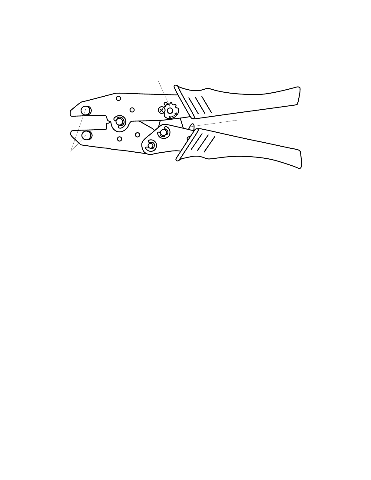
1300 Series Crimpers
Operating Instructions:
1. Install the required die set in the crimp tool by
removing the thumb screws located in the jaws.
Install the die set with the text facing outward
when crimper is in position shown above.
2. Install the thumb screws & tighten to maximum
thumb tightness. Note: Do not use pliers or tools
to tighten the thumb screws—only hand tightening is necessary.
3. Assemble cable & connector as specified by the
connector & cable manufacturers’ instructions.
4. Insert connector/cable assembly into the die set &
squeeze the handles through a complete ratchet
cycle. Crimp is complete.
Emergency release:
In the case of an emergency where a crimp cycle is
stopped & the tool needs to be reopened, flip the
safety release forward in the direction of the jaws to
engage the release mechanism.
Ratchet strength adjustment:
See page 11 for optimum ratchet gear settings &
adjustments.
Ratchet strength
adjustment
Safety release
Thumb screws

Paladin Tools
®
9
8000/CrimpALL® Series Crimpers
Safety release
Operating Instructions:
1. Install the required die set in the crimp tool by
removing the thumb screws located in the jaws.
Install the die set with the text facing outward
when crimper is in position shown above.
2. Install the thumb screws & tighten to maximum
thumb tightness. Note: Do not use pliers or tools
to tighten the thumb screws—only hand tightening is necessary.
3. Assemble cable & connector as specified by the
connector & cable manufacturers’ instructions.
4. Insert connector/cable assembly into the die set &
squeeze the handles through a complete ratchet
cycle. Crimp is complete.
Emergency release:
In the case of an emergency where a crimp cycle is
stopped & the tool needs to be reopened, flip the
safety release forward in the direction of the jaws to
engage the release mechanism.
Ratchet strength adjustment:
See page 11 for optimum ratchet gear settings &
adjustments.
Thumb screws
Ratchet strength
adjustment
Tool Operation and Use Guide
10
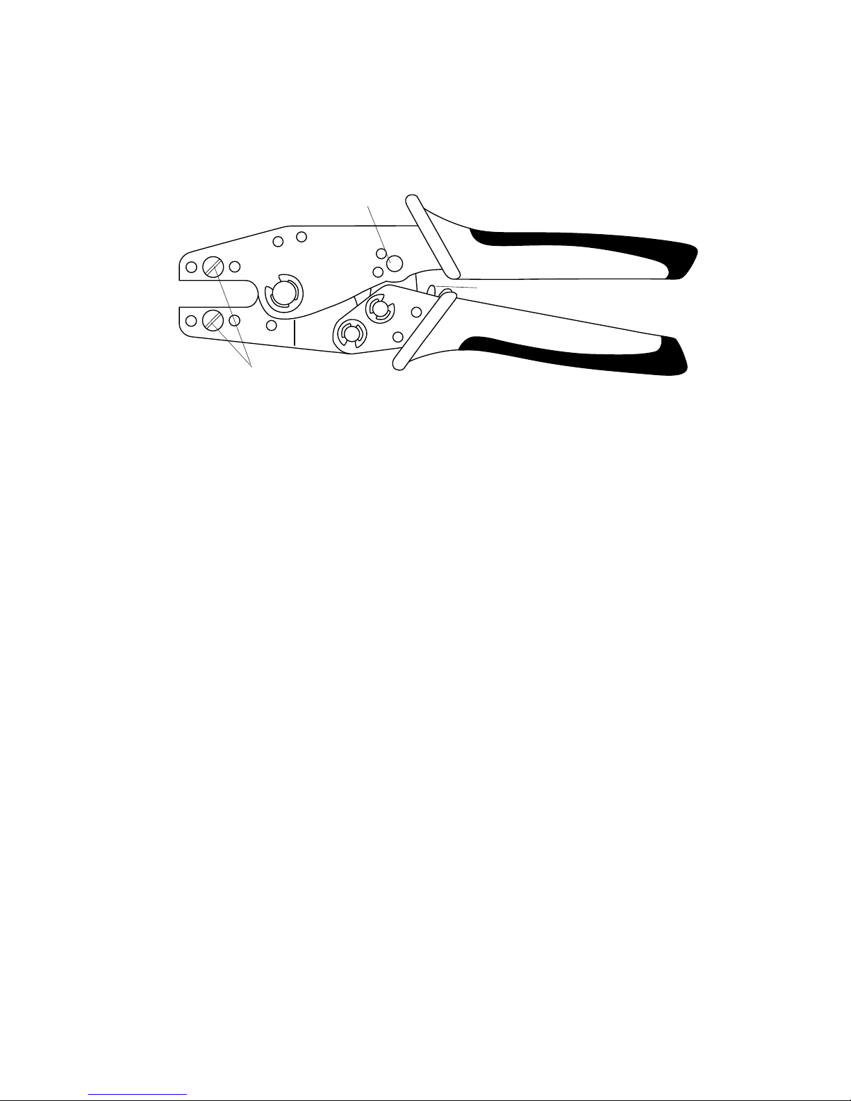
1600 Series Crimpers
To crimp a cable assembly:
1. For interchangeable-die crimp tools, install the
required die set in the crimp tool by removing the
screws located in the jaws. Install the die set in
the jaws & tighten the screws to securely hold the
die set.
2. Assemble cable & connector as specified by the
connector & cable manufacturers’ instructions.
3. Insert connector/cable assembly into the die set &
squeeze the handles through a complete ratchet
cycle. Crimp is complete.
Emergency release:
In the case of an emergency where a crimp cycle is
stopped & the tool needs to be reopened, flip the
safety release forward in the direction of the jaws to
engage the release mechanism. The release is located
between the handles.
Ratchet strength adjustment:
See page 11 for optimum ratchet gear settings &
adjustments.
Ratchet strength
adjustment
Safety release
Die screws
 Loading...